EP2735924A1 - Providing improvements in relation to a model of a process - Google Patents
Providing improvements in relation to a model of a process Download PDFInfo
- Publication number
- EP2735924A1 EP2735924A1 EP13166342.9A EP13166342A EP2735924A1 EP 2735924 A1 EP2735924 A1 EP 2735924A1 EP 13166342 A EP13166342 A EP 13166342A EP 2735924 A1 EP2735924 A1 EP 2735924A1
- Authority
- EP
- European Patent Office
- Prior art keywords
- excitation signal
- excitation
- signal
- model
- control device
- Prior art date
- Legal status (The legal status is an assumption and is not a legal conclusion. Google has not performed a legal analysis and makes no representation as to the accuracy of the status listed.)
- Withdrawn
Links
- 238000000034 method Methods 0.000 title claims abstract description 220
- 230000008569 process Effects 0.000 title claims abstract description 188
- 230000006872 improvement Effects 0.000 title claims abstract description 17
- 230000005284 excitation Effects 0.000 claims abstract description 185
- 230000004044 response Effects 0.000 claims abstract description 73
- 238000004886 process control Methods 0.000 claims abstract description 22
- 238000004590 computer program Methods 0.000 claims abstract description 15
- 230000006870 function Effects 0.000 claims description 50
- 238000012545 processing Methods 0.000 claims description 37
- 230000003068 static effect Effects 0.000 claims description 21
- 238000012905 input function Methods 0.000 claims description 17
- 238000012886 linear function Methods 0.000 claims description 14
- 230000015654 memory Effects 0.000 claims description 12
- 238000012546 transfer Methods 0.000 claims description 9
- 238000013178 mathematical model Methods 0.000 claims description 5
- 239000013598 vector Substances 0.000 description 11
- 230000000694 effects Effects 0.000 description 7
- 238000004519 manufacturing process Methods 0.000 description 7
- 238000000695 excitation spectrum Methods 0.000 description 5
- 238000002474 experimental method Methods 0.000 description 5
- 238000005259 measurement Methods 0.000 description 5
- 230000008901 benefit Effects 0.000 description 3
- 238000013459 approach Methods 0.000 description 2
- 230000006399 behavior Effects 0.000 description 2
- 238000013016 damping Methods 0.000 description 2
- 230000001419 dependent effect Effects 0.000 description 2
- 230000010355 oscillation Effects 0.000 description 2
- 238000001228 spectrum Methods 0.000 description 2
- 238000012360 testing method Methods 0.000 description 2
- 241000196324 Embryophyta Species 0.000 description 1
- 238000012369 In process control Methods 0.000 description 1
- 230000005540 biological transmission Effects 0.000 description 1
- 230000008859 change Effects 0.000 description 1
- 238000001311 chemical methods and process Methods 0.000 description 1
- 238000011217 control strategy Methods 0.000 description 1
- 238000013461 design Methods 0.000 description 1
- 238000011156 evaluation Methods 0.000 description 1
- 235000013305 food Nutrition 0.000 description 1
- 238000010965 in-process control Methods 0.000 description 1
- 239000011159 matrix material Substances 0.000 description 1
- 230000000704 physical effect Effects 0.000 description 1
- 238000000746 purification Methods 0.000 description 1
- 238000005245 sintering Methods 0.000 description 1
- 239000000126 substance Substances 0.000 description 1
- XLYOFNOQVPJJNP-UHFFFAOYSA-N water Substances O XLYOFNOQVPJJNP-UHFFFAOYSA-N 0.000 description 1
Images



Classifications
-
- G—PHYSICS
- G05—CONTROLLING; REGULATING
- G05B—CONTROL OR REGULATING SYSTEMS IN GENERAL; FUNCTIONAL ELEMENTS OF SUCH SYSTEMS; MONITORING OR TESTING ARRANGEMENTS FOR SUCH SYSTEMS OR ELEMENTS
- G05B13/00—Adaptive control systems, i.e. systems automatically adjusting themselves to have a performance which is optimum according to some preassigned criterion
- G05B13/02—Adaptive control systems, i.e. systems automatically adjusting themselves to have a performance which is optimum according to some preassigned criterion electric
- G05B13/04—Adaptive control systems, i.e. systems automatically adjusting themselves to have a performance which is optimum according to some preassigned criterion electric involving the use of models or simulators
- G05B13/042—Adaptive control systems, i.e. systems automatically adjusting themselves to have a performance which is optimum according to some preassigned criterion electric involving the use of models or simulators in which a parameter or coefficient is automatically adjusted to optimise the performance
- G05B13/045—Adaptive control systems, i.e. systems automatically adjusting themselves to have a performance which is optimum according to some preassigned criterion electric involving the use of models or simulators in which a parameter or coefficient is automatically adjusted to optimise the performance using a perturbation signal
-
- G—PHYSICS
- G05—CONTROLLING; REGULATING
- G05B—CONTROL OR REGULATING SYSTEMS IN GENERAL; FUNCTIONAL ELEMENTS OF SUCH SYSTEMS; MONITORING OR TESTING ARRANGEMENTS FOR SUCH SYSTEMS OR ELEMENTS
- G05B2219/00—Program-control systems
- G05B2219/20—Pc systems
- G05B2219/25—Pc structure of the system
- G05B2219/25298—System identification
Definitions
- the invention relates to the field of process control systems.
- the invention more particularly concerns a method, excitation arrangement, control device, control system and computer program product for providing improvements in relation to a model of a process being controlled in the process control system.
- Model based control is a powerful tool used in process control systems. Model based control is for instance described in WO 2007/001252 .
- Model based control for example model predictive control (MPC) - relies on having a model that mimics the behaviour of the actual controlled process well enough. Directly after commissioning, this is normally the case. But usually reality starts to diverge from the model so that within a few months, or at most a couple of years, it becomes necessary to update the model. To do this it would be preferable to make closed loop identification experiments which do not disturb the production more than necessary. If there is an indication about the way the model has become uncertain, the experiment should be designed to excite optimally with respect to that. This means that the desired spectrum is defined. But when the excitation is applied in a closed loop, the feedback will counteract the excitation, so the desired excitation spectrum is not obtained. In the case of completely linear control, it is possible to calculate what additional signal should be supplied in order to get the desired excitation spectrum in closed loop. However, this approach is usually not feasible with MPC.
- MPC model predictive control
- This object is according to a first aspect of the invention achieved through a method for providing improvements in relation to a model of a process being controlled in a process control system, the process control system being controlled via a control device using the model, the method comprising the steps of:
- a second aspect of the invention is directed to an excitation arrangement for providing improvements in relation to a model of a process being controlled in a process control system, the process being controlled via a control device using the model, the excitation arrangement comprising:
- a third aspect of the invention is directed towards a control device comprising the excitation arrangement according to the second aspect.
- a fourth aspect is directed towards a process control system comprising an excitation arrangement according to the third aspect.
- a fifth aspect of the invention is directed to a computer program product providing improvements in relation to a model of a process being controlled in a process control system, the process being controlled via a control device using the model, the computer program product comprising a data carrier with computer program code being loadable into one or more internal memories of one or more computer, the computer program code causing the one or more computers to, when being loaded in the one or more internal memories, provide an excitation signal, add the excitation signal to an output signal from the control device for supply as a control signal to the process, receive a process response, adjust the process response through removing the influence of the excitation signal from the process response, and supply the adjusted process response to the control device.
- the invention has a number of advantages. It provides improvements in relation to the mathematical model of the process that is controlled. For instance, process responses can be obtained when the control signal comprises the excitation signal. Excitation is thereby possible when the process is controlled in a closed loop. Through the removal of the estimated influence of the excitation signal on the process response, it is furthermore possible that the excitation signal will have full influence on the process response which will be an advantage when making improvements in relation to the model. However, since these influences are not allowed to reach the control device, the control as such will not be influenced. Furthermore, the control device will in this way be stopped from distorting the excitation signal. Thereby higher quality data is obtained compared with if the effects of the excitation signal are not removed.
- Fig. 1 schematically shows a control system 10 controlling a process 28 or a part of a process.
- the control system 10 is thus a process control system.
- the process 28 may be an industrial process and may furthermore be any of a number of different types of processes such as a pulp and paper production process, a water purification and distribution process, oil and gas production and distribution process, petrochemical, chemical, pharmaceutical and food process, an electric power transmission process or an electric power distribution process. These are just some examples of processes where the system 10 can be applied. There exist countless other processes.
- the process control system 10 includes a number of computers 12 and 14 connected to a first bus B1.
- a first computer 12 that is a first operator terminal and a second computer that is an engineering terminal 14.
- a control computer 16 providing control of the process 28.
- To the second bus B2 there are furthermore connected process interface devices 20, 22, 24 and 26 for providing control of the process 28.
- process interface devices 20, 22, 24 and 26 are sometimes referred to as field devices and are also real world objects involved in the control of the process. They are thus controlled by the control computer 16.
- process interface devices 20, 22, 24 and 26 that interfaces the process 28. It should however be realized that there may be more or fewer of each of these devices.
- Such devices are thus all involved in controlling the process 28 and in doing this one or more may be involved in measuring physical properties related to the process.
- the measured properties may here be properties of the process itself such as a voltage of or current running in a power line or the pulp temperature of a pulp and paper process.
- the control computer 16 normally has some local software for controlling one or more process interface devices, which may be different entities that influence the industrial or technical process, like such things as a pump, a motor, a valve, a tank etc. for instance realized through one or more of the process interface devices 20, 22, 24 and 26.
- This part of the control computer will in the following be termed a control device.
- the control computer will furthermore comprise an excitation arrangement. The details of which will also be described later.
- the process may also be monitored through the first operator terminal 12, which communicates with the control computer.
- the first and second process interface devices are shown as providing control signals u1 and u2 to the process, while the third and fourth process interface devices are shown as receiving process responses y1 and y2 from the process 28.
- a process response may thus be one or more measured properties of the process.
- fig. 1 is simplified in that there may be a layer of controllers, for instance PID controllers, between the control computer and the process interface devices.
- the control computer may then provide set points for the controllers, which in turn control the process interface devices based on these set points.
- Fig. 2 schematically shows a control device 30, an excitation arrangement 32 as well as elements representing the process and external influences on the process.
- the view in fig. 2 depicts a multiple input/output scenario, where the signals would be vectors of signal values.
- a control signal vector u may thus be made up both the control signals u1 and u2, while a process response y may be made up of both the signals y1 and y2 in fig. 1 .
- a multiple input/multiple output system is described, it should be realized that also other types of systems can be envisioned, such as a single input/single output, single input/multiple output or a multiple input/ single output system.
- control signals but then control signal vectors are contemplated.
- models which can be expressed in state space form or as transfer function matrices, to name just two of several possible alternatives.
- control device 30 that is responsible for ordinary control, such as model predictive control (MPC).
- the control device 30 has a first input on which it receives a control target r C , for instance from an operator. It also has a second input on which it receives a modified process response y C .
- the control device 30 has a control signal output on which it provides an output signal u C that is delivered to the excitation arrangement 32.
- the excitation arrangement 32 comprises an excitation signal generator 34, an adding unit 36 and an adjusting unit 38.
- the excitation signal generator 34 provides an excitation signal r to the adding unit 36, which adding unit 36 also receives the output signal u C of the control device 30.
- the adding unit 36 forms a control signal u , which is thus the sum of the excitation signal r and the control device output signal u C and this control signal u is provided to the process 28, where the process is assumed to respond to its input u as an (unknown) model G.
- the process 28 provides a process output y which is composed by the output of G and additional noise v.
- the process output with added noise is a process response y .
- the adjusting unit 38 comprises a processing element 40 and a subtracting element 42, where the processing element receives the excitation signal r, processes it and provides the processed excitation signal to the subtracting element 42.
- the subtracting element 42 receives the process response y and subtracts the processed excitation signal from the process response. The result is provided as adjusted process response y C that is then provided to the second input of the control device 30.
- control signal u may be made up of a number of set points for controlling controllers in a layer of controllers.
- the process may therefore from the viewpoint of the control device 30 also be considered to comprise these controllers as well as the process interface devices
- control device employs a model based control of the process 28. This means that it uses a model of the process in the control device.
- model based control may be realized, where one is outlined below.
- the model ⁇ can for example take the form of a state space model, which can be linear or non-linear.
- the input signal u is applied in a set of system equations provided through the model ⁇ of the process. This may be done through using a number q of states x, which number q may as an example be 50.
- the equations may be provided in a state space that is dependent on the number of states.
- the equations may here be non-linear equations or linear equations, which define the relationship between values of estimated measurement quantities, states of the system and the control signals. The equations thus identify relationships between system states, control signal values and estimated measurement values or system response values. The values of several different estimated measurement quantities and several different control signals may then be entered into these equations.
- k is a current instance in time being examined
- ⁇ k is an estimated process response or measurement value vector with size n at an instance in time k
- x k is state vector of size q at the instance in time k
- x k +1 is a state vector of size q at the instance in time k+1
- u k is a control signal vector of size p
- F 1 ( x k ) and F 3 ( x k ) are vector values functions of dimension q and n, respectively, of the states x at the instance in time k
- F 2 ( u k ) and F 4 ( u k ) are vector values functions of dimension q and n, respectively, of control signals u at the
- A, B, C and D are matrices with desirable system constants of the model.
- the transfer function ⁇ may then be obtained through knowledge about the matrices A, B, C and D.
- the control device thus applies a model ⁇ that mimics the actual transfer function G of the process.
- the control device 30 Based on the control target r C , the control device 30 thus controls the process 28 using the model ⁇ of the process and in this control receives a process response y which is used in the further control.
- the model ⁇ is typically fairly accurate in the beginning of operation. However, it will after some time not truly reflect the actual transfer function G of the process. It will thus deviate from reality. Reality may for instance start to diverge from the model so that within a few months, or at most a couple of years, the model may not be accurate. It may need to be updated or even changed. In order to do this new data needs to be obtained from the system.
- the invention is provided for addressing this problem.
- the adding unit 36 of the excitation arrangement 32 receives the output signal u C from the control device 30 or the control device output u C , step 44, i.e. a signal intended as a control signal by the control device 30.
- This output signal u C is thus a signal determined based on the model ⁇ , a process response y C and a control target r C .
- the excitation signal generator 34 at the same time generates an excitation signal r, step 46, which signal r is also provided to the adding unit 36 as well as to the adjusting unit 38.
- the excitation signal r may be provided in the form of a pulse train, i.e. a series of pulses set to excite various states of the process.
- the pulses of the excitation signal r may also be provided at a pulse rate set to excite various system modes. The optimal choice of such a signal is dependent on the model and its assumed accuracy and may thus vary considerably.
- the adding unit 36 then adds the excitation signal to the control device output signal u C , step 48.
- the resulting signal i.e. the signal that is the result of this adding operation, is then provided as a control signal u to the process 28, step 50.
- the control signal is thus a signal having a contribution from the excitation signal.
- the process 28 is affected by the control signal in a way which we can describe with the (unknown) model G and unknown noise v.
- the process thus provides an output signal that depends on the model G.
- This output signal is the result of the application of the control signal u in the model G, such as G * u , with addition of noise v.
- the sum forms the process response y .
- the process response y is thus a response to the control signal u made by the process 28.
- the excitation signal r is also provided to the processing element 40 of the adjusting unit 38, step 52.
- the influence of the excitation signal on the process is estimated.
- the processing element more particularly estimates the influence that the contribution of the excitation signal to the control signal has on the process. Since the whole excitation signal was used in the control signal in the first embodiment, then the contribution is 100% in this case.
- This estimation is done through processing the excitation signal. This is done through applying the excitation signal in a model of the process, which in this first embodiment is done through applying the excitation signal r in the model ⁇ of the process used by the control device 30, step 54.
- the applying may in this case involve a multiplication of the excitation signal r with the transfer function corresponding to ⁇ .
- the adjusting unit 38, or rather the processing element 40 of the adjusting unit 38 may also previously have communicated with the control device 30 in order to receive the model ⁇ .
- the processed excitation signal is then provided to the subtracting element 42.
- the subtracting element 42 also receives the process response y, step 56.
- the subtracting element 42 then subtracts the processed excitation signal from the process response y, step 60 and supplies the result as adjusted process response y C to the control device 30, step 62.
- the adding unit 36 and the subtracting element 42 may also store the control signal u and the control signal response y in the memory 43, step 64. In this way the response and the control signal can be used later in order to provide improvement in relation to the mathematical model. They may for instance be used for improving the current model ⁇ . However the data may as an alternative be used for forming a completely new model.
- the invention provides improvements in relation to the mathematical model of the process that is controlled in the process control system. For instance, as can be seen above, process responses can be obtained when the control signal comprises the excitation signal. Excitation is thus possible when the process is controlled in a closed loop. Through the removal of the estimated influence of the excitation signal on the process response, it is furthermore possible that the excitation signal will have full influence on the process response, which will be an advantage when making improvements in relation to the model. However, since these influences are not allowed to reach the control device, the control as such will not be influenced. It is thus possible to continue controlling the process according to desired control targets. Furthermore, the control device will in this way be stopped from distorting the excitation signal, which it may otherwise do. It can also be seen that higher quality data is obtained compared with if the effects of the excitation signal are not removed.
- fig. 4 shows a block schematic of the control device 30 together with an excitation arrangement 32 according to a second embodiment and elements representing the process and external influences on the process
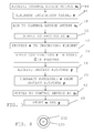
- fig. 5 shows a flow chart outlining a number of method steps of a method according to the second embodiment being performed by this excitation arrangement 32.
- the elements shown in fig. 4 differ from those in fig. 2 in that the control system comprises an input range limiter 66 between the system 28 and the adding unit 36.
- the limiter 66 is here shown as a separate entity in the system. However, it may as one alternative be a part of the control device 30. As another alternative it may be a part of the excitation arrangement 32.
- the limiter 66 has an output that faces the process 28. This limiter 66 provides a limitation to the range of the control signal u. This will have an impact on the removal of the influence of the excitation signal.
- the excitation arrangement 32 comprises a subtracting unit 68 connected between the output of the input range limiter 66 and the output of the control device 30.
- the subtracting unit 68 is thereby connected in a branch in parallel with a branch comprising the adding unit 36 and the limiter 66.
- the excitation signal generator 34 is not connected to the combination of adding unit 36 and adjusting unit 38. Instead it is only connected to the subtracting unit 68. Furthermore, also the memory has been omitted from fig. 4 .
- the method being performed in the second embodiment is the following.
- the adding unit 36 of the excitation arrangement 32 receives the control device output u C , step 70.
- the excitation signal generator 34 generates an excitation signal r', step 72. Both these signals are provided to the adding unit 36.
- the adding unit 36 then adds the excitation signal r' to the control device output signal u C , step 74.
- the obtained signal is then provided to the input range limiter 66, step 76, for obtaining a range limited control signal u.
- the range limiter 66 may for this reason apply a possible input range limitation. In the case of a single control signal, the range may for instance have a minimum and a maximum value. If then the control signal would be below the minimum value after addition of the excitation signal r' or be above the maximum value after the addition of the excitation signal r', the control signal would be limited to the range by the range limiter 66 accordingly. This means that only a part of the excitation signal r' or none of the excitation signal may in fact be input to the system. There is thus an excitation signal contribution being made, which may vary between a percentage of zero and one hundred, and it is the effect of this excitation signal contribution that has to be removed from the process response.
- the subtracting unit 68 receives the range limited or actually applied control signal u from the output of the range limiter 66, step 66, as well as the output signal u C of the control device 30. The subtracting unit 68 then subtracts the output signal u C from the control signal u and thereby obtains the excitation signal contribution r, step 80. The subtracting unit 68 then provides the contribution r to the processing element 40 of the adjusting unit 38, step 82. In the processing element 40 the influence of the excitation signal contribution r to the process is then estimated. This may, just as in the first embodiment, be done through applying the excitation signal contribution r in the model ⁇ of the process 28, step 84. The processed excitation signal contribution is then provided to the subtracting element 42.
- the subtracting element 42 also receives the process response y , step 86, and then subtracts the processed excitation signal contribution from the process response y , step 88, and supplies the result as adjusted process response y C to the control device 30, step 90.
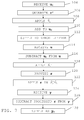
- fig. 6 shows a block schematic of the control device 30 together with an excitation arrangement 32 according to the third embodiment and elements representing the process and external influences on the process and fig. 7 shows a flow chart outlining a number of method steps of a method according to the third embodiment being performed by this excitation arrangement.
- the process 28 in fig. 6 is a non-linear process.
- the process 28 may because of this be considered to have a linear dynamic transfer function G L , a non-linear static input function N u - 1 and a non-linear static output function N y - 1 .
- the total input response of the process can then be described by N y - 1 ⁇ G L ⁇ N u - 1 .
- control device 30 has a linear processing unit 94 providing a linear dynamic model ⁇ L of the linear function, a first non-linear processing unit 96 providing a first non-linear static function N ⁇ u for the control signals and a second non-linear processing unit 98 providing a second non-linear static function N ⁇ y for the process response, where the first non-linear static function N ⁇ u of the control device 30 mimics the inverse of the static input function of the process 28 and the second non-linear static function N ⁇ y of the control device mimics the inverse of the non-linear output function of the process.
- the input function N u - 1 of the process is (ideally) the inverse of the first non-linear function N ⁇ u of the control device and the output function N y - 1 of the process is (ideally) the inverse function of the second non-linear function N ⁇ y of the control device.
- the control device 30 receives the control target r C . It also receives the adjusted system response y C , which is processed using the second static function N ⁇ y . The processed adjusted system response and the control target are then processed using the linear model ⁇ L . The results of this processing are then provided to the first static function N ⁇ u , which in turn provides the output signal u C .
- the exciting arrangement 32 comprises a first function processing unit 100 connected between the excitation signal generator 34 and the adding unit 36 and an input function processing unit 102 connected between the subtracting unit 68 and the processing element 40.
- the method being performed is the following.
- the adding unit 36 of the excitation arrangement 32 receives the control device output u C , step 104.
- the excitation signal generator 34 also generates an excitation signal r ', step 106.
- This excitation signal r' is then provided to the first function processing unit 100, which applies the first non-linear static function N ⁇ u on the generated excitation signal, step 108, for obtaining a processed excitation signal.
- This may be done through evaluation of a multivariable non-linear function expression representing N ⁇ u for the argument r '.
- the function used may be the same first non-linear static function as that employed in the control device 30.
- the first function processing unit 100 may for this reason have previously communicated with the control device 30 in order to obtain the input function.
- the processed excitation signal and the output signal u C are then both provided to the adding unit 36.
- the adding unit 36 then adds the processed excitation signal to the control device output signal u C , step 110.
- the obtained signal is then provided to the input range limiter 66, step 112, which applies a possible input range limitation in order to obtain the control signal u.
- the subtracting unit 68 receives the actually applied control signal u from the output of the range limiter 66, step 114, as well as the output signal u C from the control device 30. The subtracting unit 68 then subtracts the output signal u C from the control signal u , step 116. The result of this operation is then provided to the input function processing unit 102, which goes on and applies an estimation of the input function N ⁇ u - 1 , step 118, in order to convert the remaining excitation signal contribution to its linearized counterpart r.
- the result of the subtracting operation may in this case be the argument at which the multivariable input function estimate N ⁇ u - 1 will be evaluated.
- This input function N ⁇ u - 1 is thus an estimate of the input function N u - 1 representing part of the process 28.
- the input function processing unit 102 may have previously communicated with the control device 30 or the first function processing unit 100 for obtaining the function N ⁇ u . Based on the function N ⁇ u the input function processing unit 102 would then determine the inverse function N ⁇ u - 1 . As an alternative the control device 30 could determine the inverse function N ⁇ u - 1 and supply it to the input function processing unit 102. The input function processing unit 102 then provides the contribution or the linearized counterpart of the contribution r to the processing element 40 of the adjusting unit 38, step 120.
- the influence of the excitation signal contribution on the process is then estimated. This is done through applying the excitation signal contribution r in the model ⁇ L of the linear part of the process and in an estimate of the output function N ⁇ y - 1 , step 122.
- the estimate of the output function may be the inverse of the second non-linear static function. This may be done through feeding the excitation signal contribution r to the model ⁇ L and let the output of that define the arguments at which to evaluate the multivariable non-linear function expression representing N ⁇ y - 1 . As an alternative table look-up possibly combined with interpolation may be used instead.
- the processed excitation signal contribution is then provided to the subtracting element 42.
- the subtracting element 42 also receives the process response y, step 124, and then subtracts the processed excitation signal contribution from the process response y, step 126, and supplies the result as adjusted process response y C to the control device 30, step 128.
- the third embodiment may be varied in that it is possible to omit the limiter, in which case the subtracting unit 68 as well as the input function processing unit 102 would not be needed either.
- the excitation signal generator 34 may be directly connected to both the input function processing unit 100 and the processing element 40.
- Another possible variation of the invention is that the storing of the process control signal and process response in a memory need not be performed by the units and elements of the excitation arrangement. It is for instance possible that the control device has such functionality. This functionality may also be provided in other elements of the process control system.
- the model used in the excitation arrangement may furthermore differ from the model used in the control device. They need thus not use the same model.
- the functions used in the excitation arrangement may correspond to the functions used in the control device.
- a function in the excitation arrangement that corresponds to the first static non-linear function in the control device may perform the same type of activity.
- the functions in the excitation arrangement may thus at least correspond to functions in the control device. However, they may also be the same.
- the excitation arrangement may be realized as a separate entity which is connected to the control computer when an update is needed with regard to a used model. It may forn instance be provided in the form of a plug-in module. However, it should also be realized that it may also be provided as a part of the control computer, perhaps as a part of the control device.
- the excitation arrangement When being connected to the control device, the excitation arrangement need not be used continuously. It may only be used from time to time When the excitation arrangement is not needed, this may be achieved through avoiding application of an excitation signal or through using an excitation signal set to zero. It could also be achieved through completely bypassing the excitation arrangement.
- the excitation arrangement may be provided in the form of computer program code in a program memory.
- This computer program code performs the functionality of the excitation arrangement when being run by a processor of a computer, such as a processor of the control computer.
- This computer program code may also be provided on a data carrier which performs the functionality of the excitation arrangement when being loaded into such a program memory.
- Fig. 8 schematically shows one such data carrier 130, in the form of a CD-ROM disc, which data carrier carries computer program code 132 for performing the activities of the excitation arrangement.
Landscapes
- Engineering & Computer Science (AREA)
- Health & Medical Sciences (AREA)
- Artificial Intelligence (AREA)
- Computer Vision & Pattern Recognition (AREA)
- Evolutionary Computation (AREA)
- Medical Informatics (AREA)
- Software Systems (AREA)
- Physics & Mathematics (AREA)
- General Physics & Mathematics (AREA)
- Automation & Control Theory (AREA)
- Feedback Control In General (AREA)
Abstract
The invention is related to a method, excitation arrangement, control device, control system and computer program product for providing improvements in relation to a model of a process (28) being controlled in a process control system. The excitation arrangement comprises an excitation signal generator (34) generating an excitation signal (r) , an adding unit (36) for adding the excitation signal to an output signal (uc) from the control device for obtaining an input control signal (u) to the process (28) having an excitation signal contribution (r) and an adjusting unit (38) configured to receive a process response (y), adjust the process response through removing an estimated influence of the excitation signal contribution (r), and supply the adjusted process response (yc) to the control device.
Description
- The invention relates to the field of process control systems. The invention more particularly concerns a method, excitation arrangement, control device, control system and computer program product for providing improvements in relation to a model of a process being controlled in the process control system.
- Model based control is a powerful tool used in process control systems. Model based control is for instance described in
WO 2007/001252 . - Model based control - for example model predictive control (MPC) - relies on having a model that mimics the behaviour of the actual controlled process well enough. Directly after commissioning, this is normally the case. But usually reality starts to diverge from the model so that within a few months, or at most a couple of years, it becomes necessary to update the model. To do this it would be preferable to make closed loop identification experiments which do not disturb the production more than necessary. If there is an indication about the way the model has become uncertain, the experiment should be designed to excite optimally with respect to that. This means that the desired spectrum is defined. But when the excitation is applied in a closed loop, the feedback will counteract the excitation, so the desired excitation spectrum is not obtained. In the case of completely linear control, it is possible to calculate what additional signal should be supplied in order to get the desired excitation spectrum in closed loop. However, this approach is usually not feasible with MPC.
- Currently there are basically two routes for process identification, when the model needs to be updated or changed:
- To excite in open loop. Then the desired spectrum is obtained, but also the disadvantages of operating in open loop during the whole experiment.
- To apply the excitation in closed loop, ignoring the influence of the feedback on the achieved excitation spectrum. Then the desired excitation is not obtained, and thus the data obtained for model identification will be less informative.
- None of these two routes provides both the desired excitation spectrum and operation in closed loop. Operation in open loop implies greater risk of losing production during the experiment. Operation in closed loop, but with an excitation spectrum different from the desired one means that you need a longer experiment or higher excitation power to get enough information for the required accuracy of the model when updated by identification.
- The provision of an excitation signal in an MPC controller in a closed-loop MPC control system is for instance described by Renato N. Pitta and Darci Odloak in "Closed-loop re-identification of an industrial debutanizer column", 8th IFAC Symposium on Advanced Control of Chemical Processes, Singapore July 2012, Singapore, July 10-13, 2012.
- In "Design and application of generalized predictive control strategy with closed-loop identification for burn through point in sintering process", Control Engineering Practice 20 (2012) Min Wu, Chunseng Wang, Weihua Cao, Xuzhi Lai and Xin Chen discuss the provision of an external signal r2(t) during closed-loop identification.
-
US2006/0111858 discusses the provision of test signals during an MPC closed-loop plant test. - However, there is still a need for improvement within the field.
- It is therefore an objective of the invention to improve the obtaining of reliable data during process control in order to provide improvements in relation to the model used in the control.
- This object is according to a first aspect of the invention achieved through a method for providing improvements in relation to a model of a process being controlled in a process control system, the process control system being controlled via a control device using the model, the method comprising the steps of:
- providing an excitation signal,
- adding the excitation signal to an output signal from the control device for obtaining a control signal to the process having an excitation signal contribution,
- receiving a process response,
- adjusting the process response, said adjusting comprising removing an estimated influence of the excitation signal contribution on the process response, and
- supplying the adjusted process response to the control device.
- A second aspect of the invention is directed to an excitation arrangement for providing improvements in relation to a model of a process being controlled in a process control system, the process being controlled via a control device using the model, the excitation arrangement comprising:
- an excitation signal generator generating an excitation signal,
- an adding unit for adding the excitation signal to an output signal from the control device for obtaining a control signal to the process having an excitation signal contribution, and
- an adjusting unit configured to receive a process response, adjust the process response through removing an estimated influence of the excitation signal contribution, and supply the adjusted process response to the control device.
- A third aspect of the invention is directed towards a control device comprising the excitation arrangement according to the second aspect.
- A fourth aspect is directed towards a process control system comprising an excitation arrangement according to the third aspect.
- A fifth aspect of the invention is directed to a computer program product providing improvements in relation to a model of a process being controlled in a process control system, the process being controlled via a control device using the model, the computer program product comprising a data carrier with computer program code being loadable into one or more internal memories of one or more computer, the computer program code causing the one or more computers to, when being loaded in
the one or more internal memories,
provide an excitation signal,
add the excitation signal to an output signal from the control device for supply as a control signal to the process,
receive a process response,
adjust the process response through removing the influence of the excitation signal from the process response, and
supply the adjusted process response to the control device. - The invention according to these aspects has a number of advantages. It provides improvements in relation to the mathematical model of the process that is controlled. For instance, process responses can be obtained when the control signal comprises the excitation signal. Excitation is thereby possible when the process is controlled in a closed loop. Through the removal of the estimated influence of the excitation signal on the process response, it is furthermore possible that the excitation signal will have full influence on the process response which will be an advantage when making improvements in relation to the model. However, since these influences are not allowed to reach the control device, the control as such will not be influenced. Furthermore, the control device will in this way be stopped from distorting the excitation signal. Thereby higher quality data is obtained compared with if the effects of the excitation signal are not removed.
- The subject matter of the invention will be explained in more detail in the following text with reference being made to preferred exemplary embodiments which are illustrated in the attached drawings, of which:
-
Fig. 1 schematically shows a process control system comprising a control computer for controlling an industrial process, -
Fig. 2 shows a block schematic of a control device, an excitation arrangement according to a first embodiment and elements representing the process and external influences on the process, -
Fig. 3 shows a flow chart outlining a number of method steps of a method according to the first embodiment being performed by the excitation arrangement infig. 2 , -
Fig. 4 shows a block schematic of the control device, an excitation arrangement according to a second embodiment and elements representing the process and external influences on the process, -
Fig. 5 shows a flow chart outlining a number of method steps of a method according to the second embodiment being performed by the excitation arrangement infig. 4 , -
Figure 6 shows a block schematic of the control device together with an excitation arrangement according to a third embodiment and elements representing the process and external influences on the process -
Fig. 7 shows a flow chart outlining a number of method steps of a method according to the third embodiment being performed by the excitation arrangement infig. 6 , and -
Fig. 8 schematically shows a computer program product comprising computer readable code which implements the excitation arrangement when loaded into a computer. - In the following description, for purposes of explanation and not limitation, specific details are set forth such as particular architectures, interfaces, techniques, etc. in order to provide a thorough understanding of the present invention. However, it will be apparent to those skilled in the art that the present invention may be practiced in other embodiments that depart from these specific details. In other instances, detailed descriptions of well known devices, circuits, and methods are omitted so as not to obscure the description of the present invention with unnecessary detail.
-
Fig. 1 schematically shows acontrol system 10 controlling aprocess 28 or a part of a process. Thecontrol system 10 is thus a process control system. Theprocess 28 may be an industrial process and may furthermore be any of a number of different types of processes such as a pulp and paper production process, a water purification and distribution process, oil and gas production and distribution process, petrochemical, chemical, pharmaceutical and food process, an electric power transmission process or an electric power distribution process. These are just some examples of processes where thesystem 10 can be applied. There exist countless other processes. - In
fig. 1 theprocess control system 10 includes a number ofcomputers first computer 12 that is a first operator terminal and a second computer that is anengineering terminal 14. There is furthermore a second bus B2 and between the first and second busses there is connected acontrol computer 16 providing control of theprocess 28. To the second bus B2 there are furthermore connectedprocess interface devices process 28. These devices are sometimes referred to as field devices and are also real world objects involved in the control of the process. They are thus controlled by thecontrol computer 16. In the figure there are provided four suchprocess interface devices process 28. It should however be realized that there may be more or fewer of each of these devices. Such devices are thus all involved in controlling theprocess 28 and in doing this one or more may be involved in measuring physical properties related to the process. The measured properties may here be properties of the process itself such as a voltage of or current running in a power line or the pulp temperature of a pulp and paper process. - It should also be realised that there may be many more control computers as well as more engineering and operator terminals.
- The
control computer 16 normally has some local software for controlling one or more process interface devices, which may be different entities that influence the industrial or technical process, like such things as a pump, a motor, a valve, a tank etc. for instance realized through one or more of theprocess interface devices first operator terminal 12, which communicates with the control computer. - In
fig. 1 the first and second process interface devices are shown as providing control signals u1 and u2 to the process, while the third and fourth process interface devices are shown as receiving process responses y1 and y2 from theprocess 28. A process response may thus be one or more measured properties of the process. - It should be realized that
fig. 1 is simplified in that there may be a layer of controllers, for instance PID controllers, between the control computer and the process interface devices. The control computer may then provide set points for the controllers, which in turn control the process interface devices based on these set points. -
Fig. 2 schematically shows acontrol device 30, anexcitation arrangement 32 as well as elements representing the process and external influences on the process. The view infig. 2 depicts a multiple input/output scenario, where the signals would be vectors of signal values. A control signal vector u may thus be made up both the control signals u1 and u2, while a process response y may be made up of both the signals y1 and y2 infig. 1 . Even though a multiple input/multiple output system is described, it should be realized that also other types of systems can be envisioned, such as a single input/single output, single input/multiple output or a multiple input/ single output system. In the following reference will be made to control signals, but then control signal vectors are contemplated. In the following there will also be reference to models which can be expressed in state space form or as transfer function matrices, to name just two of several possible alternatives. - In the control computer there is thus a
control device 30 that is responsible for ordinary control, such as model predictive control (MPC). Thecontrol device 30 has a first input on which it receives a control target rC , for instance from an operator. It also has a second input on which it receives a modified process response yC . Thecontrol device 30 has a control signal output on which it provides an output signal uC that is delivered to theexcitation arrangement 32. Theexcitation arrangement 32 comprises anexcitation signal generator 34, an addingunit 36 and an adjustingunit 38. Theexcitation signal generator 34 provides an excitation signal r to the addingunit 36, which addingunit 36 also receives the output signal uC of thecontrol device 30. The addingunit 36 forms a control signal u, which is thus the sum of the excitation signal r and the control device output signal uC and this control signal u is provided to theprocess 28, where the process is assumed to respond to its input u as an (unknown) model G. Theprocess 28 provides a process output y which is composed by the output of G and additional noise v. Thus, the process output with added noise is a process response y. The adjustingunit 38 comprises aprocessing element 40 and a subtractingelement 42, where the processing element receives the excitation signal r, processes it and provides the processed excitation signal to the subtractingelement 42. The subtractingelement 42 receives the process response y and subtracts the processed excitation signal from the process response. The result is provided as adjusted process response yC that is then provided to the second input of thecontrol device 30. - As described earlier the control signal u may be made up of a number of set points for controlling controllers in a layer of controllers. The process may therefore from the viewpoint of the
control device 30 also be considered to comprise these controllers as well as the process interface devices - There is also a
memory 43, in which the control signal u and the process response y get stored. - As was mentioned above, the control device employs a model based control of the
process 28. This means that it uses a model of the process in the control device. - There are a number of ways in which model based control may be realized, where one is outlined below.
- The process may be modeled according to ŷ = Ĝ u, where Ĝ is a mathematical model for example in the form of a matrix including a number of transfer functions, ŷ is a vector of estimated measurement values and u is a vector of control signal values. Ĝ resembles the unknown model G that describes the true behavior of the process. As alternative to transfer functions the model Ĝ can for example take the form of a state space model, which can be linear or non-linear.
- The input signal u is applied in a set of system equations provided through the model Ĝ of the process. This may be done through using a number q of states x, which number q may as an example be 50. The equations may be provided in a state space that is dependent on the number of states. The equations may here be non-linear equations or linear equations, which define the relationship between values of estimated measurement quantities, states of the system and the control signals. The equations thus identify relationships between system states, control signal values and estimated measurement values or system response values. The values of several different estimated measurement quantities and several different control signals may then be entered into these equations.
- If there are n process responses or estimated quantities, q states and p inputs or control signals, then the equations may be generally expressed as:


where k is a current instance in time being examined ŷk is an estimated process response or measurement value vector with size n at an instance in time k, xk is state vector of size q at the instance in time k, x k+1 is a state vector of size q at the instance in time k+1, uk is a control signal vector of size p, F 1(xk ) and F 3(xk ) are vector values functions of dimension q and n, respectively, of the states x at the instance in time k, while F 2(uk ) and F 4(uk ) are vector values functions of dimension q and n, respectively, of control signals u at the instance in time k. Here the functions can be non-linear but also linear. - If the functions are linear, the equations can furthermore be simplified as:


where A, B, C and D are matrices with desirable system constants of the model. The transfer function Ĝ may then be obtained through knowledge about the matrices A, B, C and D. - The control device thus applies a model Ĝ that mimics the actual transfer function G of the process.
- Based on the control target rC, the
control device 30 thus controls theprocess 28 using the model Ĝ of the process and in this control receives a process response y which is used in the further control. - As was mentioned earlier, the model Ĝ is typically fairly accurate in the beginning of operation. However, it will after some time not truly reflect the actual transfer function G of the process. It will thus deviate from reality. Reality may for instance start to diverge from the model so that within a few months, or at most a couple of years, the model may not be accurate. It may need to be updated or even changed. In order to do this new data needs to be obtained from the system.
- One way of obtaining data for use in such model update or change is through providing an excitation signal that is added to the control signal and used during the closed loop control. This is of interest for several reasons, where one is that it may be desirable to maintain production and another may be that data obtained in closed loop will better reflects the true properties of the process as it is operated normally. However, there is a problem with this approach and that is that the excitation signal also influences the control. This means that the control system also acts on the responses to the excitation, which may lead to a control signal from the control device that in part is a countermeasure to the effects of the excitation signal. This will in turn lead to a process response that to a lower degree reflects the effect of the intended excitation. This will give less informative data, and thus make the model updating less efficient, compared to the case that the same excitation had been fed in open loop.
- The invention is provided for addressing this problem.
- A first embodiment of the invention will therefore now be described with reference being made to
fig. 1 - 2 together withfig. 3 , which shows a flow chart outlining a number of method steps of a method according to the first embodiment being performed by theexcitation arrangement 32. - The adding
unit 36 of theexcitation arrangement 32 receives the output signal uC from thecontrol device 30 or the control device output uC ,step 44, i.e. a signal intended as a control signal by thecontrol device 30. This output signal uC is thus a signal determined based on the model Ĝ, a process response yC and a control target rC . - The
excitation signal generator 34 at the same time generates an excitation signal r,step 46, which signal r is also provided to the addingunit 36 as well as to the adjustingunit 38. - The excitation signal r may be provided in the form of a pulse train, i.e. a series of pulses set to excite various states of the process. The pulses of the excitation signal r may also be provided at a pulse rate set to excite various system modes. The optimal choice of such a signal is dependent on the model and its assumed accuracy and may thus vary considerably.
- The adding
unit 36 then adds the excitation signal to the control device output signal uC ,step 48. The resulting signal, i.e. the signal that is the result of this adding operation, is then provided as a control signal u to theprocess 28,step 50. The control signal is thus a signal having a contribution from the excitation signal. Theprocess 28 is affected by the control signal in a way which we can describe with the (unknown) model G and unknown noise v. The process thus provides an output signal that depends on the model G. This output signal is the result of the application of the control signal u in the model G, such as G*u, with addition of noise v. The sum forms the process response y. The process response y is thus a response to the control signal u made by theprocess 28. - Apart from being added to the control device output signal uC and supplied to the
process 28, the excitation signal r is also provided to theprocessing element 40 of the adjustingunit 38,step 52. In the processing element the influence of the excitation signal on the process is estimated. The processing element more particularly estimates the influence that the contribution of the excitation signal to the control signal has on the process. Since the whole excitation signal was used in the control signal in the first embodiment, then the contribution is 100% in this case. This estimation is done through processing the excitation signal. This is done through applying the excitation signal in a model of the process, which in this first embodiment is done through applying the excitation signal r in the model Ĝ of the process used by thecontrol device 30,step 54. The applying may in this case involve a multiplication of the excitation signal r with the transfer function corresponding to Ĝ. In order to perform the operation, the adjustingunit 38, or rather theprocessing element 40 of the adjustingunit 38, may also previously have communicated with thecontrol device 30 in order to receive the model Ĝ. The processed excitation signal is then provided to the subtractingelement 42. - The subtracting
element 42 also receives the process response y,step 56. The subtractingelement 42 then subtracts the processed excitation signal from the process response y, step 60 and supplies the result as adjusted process response yC to thecontrol device 30,step 62. - The adding
unit 36 and the subtractingelement 42 may also store the control signal u and the control signal response y in thememory 43,step 64. In this way the response and the control signal can be used later in order to provide improvement in relation to the mathematical model. They may for instance be used for improving the current model Ĝ. However the data may as an alternative be used for forming a completely new model. - The invention provides improvements in relation to the mathematical model of the process that is controlled in the process control system. For instance, as can be seen above, process responses can be obtained when the control signal comprises the excitation signal. Excitation is thus possible when the process is controlled in a closed loop. Through the removal of the estimated influence of the excitation signal on the process response, it is furthermore possible that the excitation signal will have full influence on the process response, which will be an advantage when making improvements in relation to the model. However, since these influences are not allowed to reach the control device, the control as such will not be influenced. It is thus possible to continue controlling the process according to desired control targets. Furthermore, the control device will in this way be stopped from distorting the excitation signal, which it may otherwise do. It can also be seen that higher quality data is obtained compared with if the effects of the excitation signal are not removed.
- Now a second embodiment will be described with reference being made to
fig. 4 and5 , wherefig. 4 shows a block schematic of thecontrol device 30 together with anexcitation arrangement 32 according to a second embodiment and elements representing the process and external influences on the process andfig. 5 shows a flow chart outlining a number of method steps of a method according to the second embodiment being performed by thisexcitation arrangement 32. - The elements shown in
fig. 4 differ from those infig. 2 in that the control system comprises aninput range limiter 66 between thesystem 28 and the addingunit 36. Thelimiter 66 is here shown as a separate entity in the system. However, it may as one alternative be a part of thecontrol device 30. As another alternative it may be a part of theexcitation arrangement 32. Thelimiter 66 has an output that faces theprocess 28. Thislimiter 66 provides a limitation to the range of the control signal u. This will have an impact on the removal of the influence of the excitation signal. In order to handle this situation, theexcitation arrangement 32 comprises a subtractingunit 68 connected between the output of theinput range limiter 66 and the output of thecontrol device 30. The subtractingunit 68 is thereby connected in a branch in parallel with a branch comprising the addingunit 36 and thelimiter 66. Theexcitation signal generator 34 is not connected to the combination of addingunit 36 and adjustingunit 38. Instead it is only connected to the subtractingunit 68. Furthermore, also the memory has been omitted fromfig. 4 . - The method being performed in the second embodiment is the following.
- The adding
unit 36 of theexcitation arrangement 32 receives the control device output uC,step 70. Theexcitation signal generator 34 generates an excitation signal r',step 72. Both these signals are provided to the addingunit 36. - The adding
unit 36 then adds the excitation signal r' to the control device output signal uC,step 74. The obtained signal is then provided to theinput range limiter 66,step 76, for obtaining a range limited control signal u. Therange limiter 66 may for this reason apply a possible input range limitation. In the case of a single control signal, the range may for instance have a minimum and a maximum value. If then the control signal would be below the minimum value after addition of the excitation signal r' or be above the maximum value after the addition of the excitation signal r', the control signal would be limited to the range by therange limiter 66 accordingly. This means that only a part of the excitation signal r' or none of the excitation signal may in fact be input to the system. There is thus an excitation signal contribution being made, which may vary between a percentage of zero and one hundred, and it is the effect of this excitation signal contribution that has to be removed from the process response. - Therefore the subtracting
unit 68 receives the range limited or actually applied control signal u from the output of therange limiter 66,step 66, as well as the output signal uC of thecontrol device 30. The subtractingunit 68 then subtracts the output signal uC from the control signal u and thereby obtains the excitation signal contribution r,step 80. The subtractingunit 68 then provides the contribution r to theprocessing element 40 of the adjustingunit 38,step 82. In theprocessing element 40 the influence of the excitation signal contribution r to the process is then estimated. This may, just as in the first embodiment, be done through applying the excitation signal contribution r in the model Ĝ of theprocess 28,step 84. The processed excitation signal contribution is then provided to the subtractingelement 42. - The subtracting
element 42 also receives the process response y,step 86, and then subtracts the processed excitation signal contribution from the process response y,step 88, and supplies the result as adjusted process response yC to thecontrol device 30,step 90. - This may again be followed by the subtracting
unit 68 and the subtractingelement 42 storing the actual control signal u and the process response y in a memory (not shown). - Now a third embodiment will be described, with reference being made to
fig. 6 and7 , wherefig. 6 shows a block schematic of thecontrol device 30 together with anexcitation arrangement 32 according to the third embodiment and elements representing the process and external influences on the process andfig. 7 shows a flow chart outlining a number of method steps of a method according to the third embodiment being performed by this excitation arrangement. - The
process 28 infig. 6 is a non-linear process. Theprocess 28 may because of this be considered to have a linear dynamic transfer function GL, a non-linear static input function


control device 30 has alinear processing unit 94 providing a linear dynamic model ĜL of the linear function, a firstnon-linear processing unit 96 providing a first non-linear static function N̂u for the control signals and a secondnon-linear processing unit 98 providing a second non-linear static function N̂y for the process response, where the first non-linear static function N̂u of thecontrol device 30 mimics the inverse of the static input function of theprocess 28 and the second non-linear static function N̂y of the control device mimics the inverse of the non-linear output function of the process. This also means that the input function

fig. 6 . The models and the functions of the control device are furthermore estimates. As can be seen infig. 6 , thecontrol device 30 receives the control target rC . It also receives the adjusted system response yC , which is processed using the second static function N̂y . The processed adjusted system response and the control target are then processed using the linear model ĜL. The results of this processing are then provided to the first static function N̂u , which in turn provides the output signal uC . - In order to be able to remove the influence of the excitation signal on the process response, the
exciting arrangement 32 comprises a firstfunction processing unit 100 connected between theexcitation signal generator 34 and the addingunit 36 and an inputfunction processing unit 102 connected between the subtractingunit 68 and theprocessing element 40. - The method being performed is the following.
- The adding
unit 36 of theexcitation arrangement 32 receives the control device output uC,step 104. Theexcitation signal generator 34 also generates an excitation signal r',step 106. This excitation signal r' is then provided to the firstfunction processing unit 100, which applies the first non-linear static function N̂u on the generated excitation signal,step 108, for obtaining a processed excitation signal. This may be done through evaluation of a multivariable non-linear function expression representing N̂u for the argument r'. As an alternative table look-up possibly combined with interpolation may be used instead. The function used may be the same first non-linear static function as that employed in thecontrol device 30. The firstfunction processing unit 100 may for this reason have previously communicated with thecontrol device 30 in order to obtain the input function. The processed excitation signal and the output signal uC are then both provided to the addingunit 36. - The adding
unit 36 then adds the processed excitation signal to the control device output signal uC ,step 110. The obtained signal is then provided to theinput range limiter 66,step 112, which applies a possible input range limitation in order to obtain the control signal u. - In order to handle the removal of the excitation signal contribution, the subtracting
unit 68 receives the actually applied control signal u from the output of therange limiter 66,step 114, as well as the output signal uC from thecontrol device 30. The subtractingunit 68 then subtracts the output signal uC from the control signal u,step 116. The result of this operation is then provided to the inputfunction processing unit 102, which goes on and applies an estimation of the input function
step 118, in order to convert the remaining excitation signal contribution to its linearized counterpart r. The result of the subtracting operation may in this case be the argument at which the multivariable input function estimate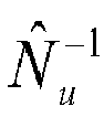


process 28. In order to obtain this function
function processing unit 102 may have previously communicated with thecontrol device 30 or the firstfunction processing unit 100 for obtaining the function N̂u. Based on the function N̂u the inputfunction processing unit 102 would then determine the inverse function
control device 30 could determine the inverse function
function processing unit 102. The inputfunction processing unit 102 then provides the contribution or the linearized counterpart of the contribution r to theprocessing element 40 of the adjustingunit 38,step 120. In theprocessing element 40 the influence of the excitation signal contribution on the process is then estimated. This is done through applying the excitation signal contribution r in the model ĜL of the linear part of the process and in an estimate of the output function
step 122. The estimate of the output function may be the inverse of the second non-linear static function. This may be done through feeding the excitation signal contribution r to the model ĜL and let the output of that define the arguments at which to evaluate the multivariable non-linear function expression representing
element 42. - The subtracting
element 42 also receives the process response y,step 124, and then subtracts the processed excitation signal contribution from the process response y,step 126, and supplies the result as adjusted process response yC to thecontrol device 30,step 128. - This may again be followed by the subtracting
unit 68 and the subtractingelement 42 storing the actual control signal u and the process response y in a memory (not shown). - It should here be realized that the third embodiment may be varied in that it is possible to omit the limiter, in which case the subtracting
unit 68 as well as the inputfunction processing unit 102 would not be needed either. In this case theexcitation signal generator 34 may be directly connected to both the inputfunction processing unit 100 and theprocessing element 40. - Another possible variation of the invention is that the storing of the process control signal and process response in a memory need not be performed by the units and elements of the excitation arrangement. It is for instance possible that the control device has such functionality. This functionality may also be provided in other elements of the process control system.
- The model used in the excitation arrangement may furthermore differ from the model used in the control device. They need thus not use the same model. In this case the functions used in the excitation arrangement may correspond to the functions used in the control device. A function in the excitation arrangement that corresponds to the first static non-linear function in the control device may perform the same type of activity. The functions in the excitation arrangement may thus at least correspond to functions in the control device. However, they may also be the same.
- The excitation arrangement may be realized as a separate entity which is connected to the control computer when an update is needed with regard to a used model. It may forn instance be provided in the form of a plug-in module. However, it should also be realized that it may also be provided as a part of the control computer, perhaps as a part of the control device.
- When being connected to the control device, the excitation arrangement need not be used continuously. It may only be used from time to time When the excitation arrangement is not needed, this may be achieved through avoiding application of an excitation signal or through using an excitation signal set to zero. It could also be achieved through completely bypassing the excitation arrangement.
- The excitation arrangement may be provided in the form of computer program code in a program memory. This computer program code performs the functionality of the excitation arrangement when being run by a processor of a computer, such as a processor of the control computer. This computer program code may also be provided on a data carrier which performs the functionality of the excitation arrangement when being loaded into such a program memory.
Fig. 8 schematically shows onesuch data carrier 130, in the form of a CD-ROM disc, which data carrier carriescomputer program code 132 for performing the activities of the excitation arrangement. - Whilst the foregoing description of the invention describes a system for power oscillation damping, the skilled person will be aware that further embodiments may be envisaged where power oscillation damping is not involved. Specifically, control schemes for remote voltage control and/or control schemes for avoiding loss of synchronism. Therefore the present invention is only to be limited by the following claims.
Claims (20)
- A method for providing improvements in relation to a model of a process (28) being controlled in a process control system (10), said process control system being controlled via a control device (30) using the model, the method comprising the steps of:providing (46; 72; 106) an excitation signal (r; r'),adding (48; 74, 110) the excitation signal to an output signal (uC ) from the control device (30) for obtaining a control signal (u) to the process (28) having an excitation signal contribution (r),receiving (54; 84; 124) a process response (y),adjusting the process response, said adjusting comprising removing (60; 88; 126) an estimated influence of the excitation signal contribution on the process response, andsupplying (62; 90; 128) the adjusted process response (yC ) to the control device.
- The method according to claim 1, wherein the adjusting of the process response comprises processing (56; 86; 122) the excitation signal contribution and the removing of the estimated influence of the excitation signal contribution comprises subtracting the processed excitation signal contribution from the process response.
- The method according to claim 2, wherein the processing of the excitation signal comprises applying the excitation signal in a model of the process.
- The method according to claim 3, wherein the model is the same as that used by the control device.
- The method according to any previous claim, wherein the control signal (u) is subjected to an input range limitation and the processing comprises subtracting (80; 116) the output signal (uC ) from the control signal (u) for obtaining the excitation signal contribution.
- The method according to any of claims 1 - 4, wherein the whole excitation signal is used in the excitation signal contribution.
- The method according to any of claims 3 - 6, wherein the model comprises a dynamic linear function, a first static non-linear function and a second static non-linear function, the method further comprising applying (108) a function at least corresponding to the first static non-linear function on the excitation signal being added to the output signal and the applying (122) of the excitation signal contribution comprises applying the excitation signal contribution to a function at least corresponding to an inverse of the second static non-linear function.
- The method according to claim 7, when depending on claim 5, further comprising converting (118) the excitation signal contribution to a linearized counterpart, before said applying to the model of the system.
- The method according to any previous claim, further comprising storing the input signal and output signal obtained during application of the excitation signal.
- The method according to any previous claim, further comprising using the stored input signals and output signal for obtaining an improvement in relation to the mathematical model.
- An excitation arrangement (32) for providing improvements in relation to a model of a process (28) being controlled in a process control system (10), said process being controlled via a control device (30) using the model, the excitation arrangement (32) comprising:an excitation signal generator (34) generating an excitation signal (r; r') an adding unit (36) for adding the excitation signal to an output signal (uC ) from the control device for obtaining a control signal (u) to the process (28) having an excitation signal contribution (r), andan adjusting unit (38) configured to receive a process response (y), adjust the process response through removing an estimated influence of the excitation signal contribution (r), and supply the adjusted process response (yC ) to the control device.
- The excitation arrangement according to claim 11, wherein the adjusting unit comprises a processing element (40) configured to process the excitation signal for providing a processed excitation signal and a subtracting element (42) configured to subtract the processed excitation signal from the process response.
- The excitation arrangement according to claim 12, wherein the processing element when being configured to process the excitation signal is configured to apply the excitation signal in a model of the process.
- The excitation arrangement according to claim 13, wherein the model is the same as that used by control device.
- The excitation arrangement according to any of claims 11 - 14, wherein the control system comprises an input range limiter (66) subjecting the control signal to the process to an input range limitation and further comprising a subtracting unit (68) configured to subtract the output signal (uC ) from the control signal (u) for obtaining the excitation signal contribution.
- The excitation arrangement according to any of claims 13 - 15, wherein the model comprises a dynamic linear transfer function, a first static non-linear function and a second static non-linear output function, the arrangement further comprising a first function processing unit (100) configured to apply a function at least corresponding to the first static non-linear function on the input excitation signal and, the processing element is further configured to apply the excitation signal contribution in a function at least corresponding to an inverse of the second static non-linear function when being configured to process the excitation signal.
- The excitation arrangement according to claim 16 when depending on claim 15, further comprising an input function processing unit 102 configured to convert the excitation signal contribution to a linearized counterpart before supplying it to the adjusting unit.
- A control device (30) in a process control system (10) and controlling a process using a model of the process, the control device comprising an excitation arrangement (32) according to any of claims 11 - 17.
- A process control system (10) controlling a process (28) using a model of the process (28), the process control system (10) comprising an excitation arrangement (32) according to any of claims 11 - 17.
- A computer program product providing improvements in relation to a model of a process (28) being controlled in a process control system (10), said process being controlled via a control device (30) using the model, the computer program product comprising a data carrier (130) with computer program code (132) being loadable into one or more internal memories of one or more computer, said computer program code causing said one or more computers to, when being loaded in said one or more internal memory,
provide an excitation signal,
add the excitation signal to an output signal from the control device (30) for supply as a control signal to the process (28),
receive a process response,
adjust the process response through removing the influence of the excitation signal from the process response, and
supply the adjusted process response to the control device.
Priority Applications (1)
| Application Number | Priority Date | Filing Date | Title |
|---|---|---|---|
| EP13166342.9A EP2735924A1 (en) | 2013-05-03 | 2013-05-03 | Providing improvements in relation to a model of a process |
Applications Claiming Priority (1)
| Application Number | Priority Date | Filing Date | Title |
|---|---|---|---|
| EP13166342.9A EP2735924A1 (en) | 2013-05-03 | 2013-05-03 | Providing improvements in relation to a model of a process |
Publications (1)
| Publication Number | Publication Date |
|---|---|
| EP2735924A1 true EP2735924A1 (en) | 2014-05-28 |
Family
ID=48227030
Family Applications (1)
| Application Number | Title | Priority Date | Filing Date |
|---|---|---|---|
| EP13166342.9A Withdrawn EP2735924A1 (en) | 2013-05-03 | 2013-05-03 | Providing improvements in relation to a model of a process |
Country Status (1)
| Country | Link |
|---|---|
| EP (1) | EP2735924A1 (en) |
Citations (5)
| Publication number | Priority date | Publication date | Assignee | Title |
|---|---|---|---|---|
| US20060111858A1 (en) | 2004-11-22 | 2006-05-25 | Yucai Zhu | Computer method and apparatus for online process identification |
| WO2007001252A1 (en) | 2005-06-13 | 2007-01-04 | Carnegie Mellon University | Apparatuses, systems, and methods utilizing adaptive control |
| US20070073422A1 (en) * | 2005-09-29 | 2007-03-29 | Honeywell International, Inc. | On-demand auto-tuner for a plant control system |
| US20110130850A1 (en) * | 2009-05-29 | 2011-06-02 | Aspen Technology, Inc. | Apparatus and method for model quality estimation and model adaptation in multivariable process control |
| US20120046762A1 (en) * | 2010-08-18 | 2012-02-23 | International Business Machines Corporation | Performance improvement of signal transformation schemes for ultra-fast scanning |
-
2013
- 2013-05-03 EP EP13166342.9A patent/EP2735924A1/en not_active Withdrawn
Patent Citations (5)
| Publication number | Priority date | Publication date | Assignee | Title |
|---|---|---|---|---|
| US20060111858A1 (en) | 2004-11-22 | 2006-05-25 | Yucai Zhu | Computer method and apparatus for online process identification |
| WO2007001252A1 (en) | 2005-06-13 | 2007-01-04 | Carnegie Mellon University | Apparatuses, systems, and methods utilizing adaptive control |
| US20070073422A1 (en) * | 2005-09-29 | 2007-03-29 | Honeywell International, Inc. | On-demand auto-tuner for a plant control system |
| US20110130850A1 (en) * | 2009-05-29 | 2011-06-02 | Aspen Technology, Inc. | Apparatus and method for model quality estimation and model adaptation in multivariable process control |
| US20120046762A1 (en) * | 2010-08-18 | 2012-02-23 | International Business Machines Corporation | Performance improvement of signal transformation schemes for ultra-fast scanning |
Non-Patent Citations (2)
| Title |
|---|
| MIN WU; CHUNSENG WANG; WEIHUA CAO; XUZHI LAI; XIN CHEN: "Design and application of generalized predictive control strategy with closed-loop identification for burn through point in sintering process", CONTROL ENGINEERING PRACTICE, 2012, pages 20 |
| RENATO N. PITTA; DARCI ODLOAK: "Closed-loop re- identification of an industrial debutanizer column", 8TH IFAC SYMPOSIUM ON ADVANCED CONTROL OF CHEMICAL PROCESSES, 10 July 2012 (2012-07-10) |
Similar Documents
| Publication | Publication Date | Title |
|---|---|---|
| Ahn et al. | Adaptive backstepping control of an electrohydraulic actuator | |
| Patwardhan et al. | From data to diagnosis and control using generalized orthonormal basis filters. Part II: Model predictive and fault tolerant control | |
| Kilic et al. | Accurate pressure prediction of a servo-valve controlled hydraulic system | |
| GB2603064A (en) | Improved machine learning for technical systems | |
| Domek | Switched state model predictive control of fractional‐order nonlinear discrete‐time systems | |
| GB2547137A (en) | Rapid process model identification and generation | |
| DE112015004092T5 (en) | Control device, program for it and plant control procedures | |
| Orra et al. | Development of flank wear model of cutting tool by using adaptive feedback linear control system on machining AISI D2 steel and AISI 4340 steel | |
| JP7101806B2 (en) | Methods and corresponding devices for controlling valves | |
| US20130018612A1 (en) | Device and method for observing or controlling a non-linear system | |
| Ye et al. | Flight envelope protection control based on reference governor method in high angle of attack maneuver | |
| EP2735924A1 (en) | Providing improvements in relation to a model of a process | |
| Ji et al. | Identification and predictive control for a circulation fluidized bed boiler | |
| JP7207474B1 (en) | Information processing equipment | |
| Homaeinezhad et al. | Short‐Time Linear Quadratic Form Technique for Estimating Fast‐Varying Parameters in Feedback Loops | |
| Mohammadkhani et al. | Two-stage observer based offset-free MPC | |
| Rauh et al. | Quantification of time-domain truncation errors for the reinitialization of fractional integrators | |
| US20180350497A1 (en) | Current monitoring in a load | |
| Li et al. | A data-driven fault-tolerant control design of linear multivariable systems with performance optimization | |
| Mitov et al. | Model Predictive Control Design for Electrohydraulic Power Steering Application | |
| Chen et al. | Design and implementation of model predictive control algorithms for small satellite three-axis stabilization | |
| Ghazali et al. | Simulation and experimental studies on perfect tracking optimal control of an electrohydraulic actuator system | |
| Bajarangbali et al. | Identification of integrating and critically damped systems with time delay | |
| Jakubek et al. | 6 Controls and Identification | |
| Bukhari et al. | Model order reduction of dynamical systems: An approach to investigate real and complex poles |
Legal Events
| Date | Code | Title | Description |
|---|---|---|---|
| PUAI | Public reference made under article 153(3) epc to a published international application that has entered the european phase |
Free format text: ORIGINAL CODE: 0009012 |
|
| 17P | Request for examination filed |
Effective date: 20130503 |
|
| AK | Designated contracting states |
Kind code of ref document: A1 Designated state(s): AL AT BE BG CH CY CZ DE DK EE ES FI FR GB GR HR HU IE IS IT LI LT LU LV MC MK MT NL NO PL PT RO RS SE SI SK SM TR |
|
| AX | Request for extension of the european patent |
Extension state: BA ME |
|
| STAA | Information on the status of an ep patent application or granted ep patent |
Free format text: STATUS: THE APPLICATION HAS BEEN WITHDRAWN |
|
| 18W | Application withdrawn |
Effective date: 20140609 |