EP2735889A2 - Method of and Apparatus for Processing CSEM Data, Program, Storage Medium, Computer and Use of Method - Google Patents
Method of and Apparatus for Processing CSEM Data, Program, Storage Medium, Computer and Use of Method Download PDFInfo
- Publication number
- EP2735889A2 EP2735889A2 EP14156390.8A EP14156390A EP2735889A2 EP 2735889 A2 EP2735889 A2 EP 2735889A2 EP 14156390 A EP14156390 A EP 14156390A EP 2735889 A2 EP2735889 A2 EP 2735889A2
- Authority
- EP
- European Patent Office
- Prior art keywords
- data
- source
- weighted
- differences
- airwave
- Prior art date
- Legal status (The legal status is an assumption and is not a legal conclusion. Google has not performed a legal analysis and makes no representation as to the accuracy of the status listed.)
- Granted
Links
Images


Classifications
-
- G—PHYSICS
- G01—MEASURING; TESTING
- G01V—GEOPHYSICS; GRAVITATIONAL MEASUREMENTS; DETECTING MASSES OR OBJECTS; TAGS
- G01V3/00—Electric or magnetic prospecting or detecting; Measuring magnetic field characteristics of the earth, e.g. declination, deviation
- G01V3/08—Electric or magnetic prospecting or detecting; Measuring magnetic field characteristics of the earth, e.g. declination, deviation operating with magnetic or electric fields produced or modified by objects or geological structures or by detecting devices
- G01V3/083—Controlled source electromagnetic [CSEM] surveying
-
- G—PHYSICS
- G01—MEASURING; TESTING
- G01V—GEOPHYSICS; GRAVITATIONAL MEASUREMENTS; DETECTING MASSES OR OBJECTS; TAGS
- G01V3/00—Electric or magnetic prospecting or detecting; Measuring magnetic field characteristics of the earth, e.g. declination, deviation
- G01V3/08—Electric or magnetic prospecting or detecting; Measuring magnetic field characteristics of the earth, e.g. declination, deviation operating with magnetic or electric fields produced or modified by objects or geological structures or by detecting devices
- G01V3/083—Controlled source electromagnetic [CSEM] surveying
- G01V2003/086—Processing
Definitions
- the present invention relates to a method of processing controlled source electromagnetic data.
- the present invention also relates to a program for controlling a computer to perform such a method, a computer readable storage medium containing such a program and a computer containing such a program.
- the present invention further relates to an apparatus arranged to perform such a method and the use of such a method to reduce airwave contribution.
- the so-called airwave may represent a problem for interpreting the subsurface response.
- the term "airwave” refers to the signal that diffuses vertically upwards from the source to the sea surface, then propagates through the air at the speed of light with no attenuation, before diffusing back down through the seawater column to the sea bottom.
- there are the effects of coupling to the subsurface on the source and receiver sides by vertically travelling multiple reflected signals (Nordskag and Amundsen, 2007; Loseth, 2007).
- a method of processing controlled source electromagnetic data comprising: weighting a plurality of data records in accordance with geometrical spreading of an airwave component; and forming a difference between the weighted data records of at least one pair of the weighted data records.
- the data records may be weighted according to the cube of source-receiver offset.
- the data records may be weighted according to the fourth power of source-receiver offset.
- a method of processing controlled source electromagnetic data comprising forming a first difference between the data records of each of a plurality of pairs of data records, weighting the first differences in accordance with geometrical spreading of an airwave component, and forming a second difference between the weighted first differences of at least one pair of the weighted first differences.
- the first differences may be weighted according to the fourth power of source-receiver offset.
- the first differences may be weighted according to the fifth power of source-receiver offset.
- the method may comprise forming a plurality of differences or second differences to provide a difference field and integrating the difference field.
- a program for controlling a computer to perform a method according to the first or second aspect of the invention is provided.
- a computer-readable storage medium containing a program according to the third aspect of the invention.
- a computer containing a program according to the third aspect of the invention.
- an apparatus arranged to perform a method according to the first or second aspect of the invention.
- a seventh aspect of the invention there is provided use of a method according to the first or second aspect of the invention to reduce airwave contribution in data.
- the new technique is that the conventional inline source-receiver configuration is sufficient.
- the properly rotated (cf. L ⁇ seth and Kritski, 2008) time-domain field components are weighted with the geometrical spreading factor of the airwave before the difference field, using two nearby receivers, is calculated.
- the two receivers preferably have a separation distance above a certain offset in order to produce data above the noise floor.
- the weighted difference field is scaled by the inverse geometrical spreading factor of the airwave before the derived difference field components are processed in the same way as for standard CSEM data.
- the attenuation or removal of the airwave component may also be done in the common receiver domain. In this case, nearby located pairs of receivers are not required. For both the common receiver and source domain procedures, it may be advantageous to perform the calculations in the time domain.
- Calculation of the difference field by using two nearby receiver responses may help to reduce the amount of correlated noise in the data (Loseth et al., 2008). If the data are weighted before the differences are formed, the reduction of correlated noise is suboptimal. A way of overcoming this can be to form first order differences without weighting the data, and then perform the airwave removal by forming new second order differences using the first order differences. This involves using data from three receivers instead of two.
- the resulting field components (at least substantially) void of the airwave may be integrated in order to make the result comparable with the original total field. This also enables estimates of the airwave contribution to the original measured field component.
- a new technique is provided for removing or reducing the airwave in marine CSEM data.
- One embodiment uses pairs of receivers or pairs of source points along the towline and processes the horizontal electric and/or magnetic fields in terms of their weighted differences along the towline.
- the weights are related to the geometrical spreading of the airwave component in the data.
- This geometrical spreading factor in the horizontal field components equals to a very good approximation the horizontal offset (source-receiver distance) to the power of three.
- the horizontal electric and magnetic field components in the common source or receiver domain should be weighted with the horizontal offset to the power of three before the differences along the towline direction of the weighted field components are calculated.
- the derived difference field components contain almost no airwave signal.
- the weighted differences may be integrated in order to obtain an estimate of the total field void of the airwave. Additionally, the airwave contribution to the total field may also be estimated.
- II is the dipole moment of a dipole source and ⁇ is its azimuthal angle.
- Variables I describe the propagation of a spectrum of plane-wave components for TE and TM modes. The theoretical background to the technique will be described first.
- R sb s and R sb r are the subsurface reflection coefficients at the seabed for vertically travelling fields at the source and receiver locations, respectively.
- x 1 r and x 2 r denote the positions of receivers Rx 1 and Rx 2 , respectively, and let ⁇ 1 and ⁇ 2 denote the offsets to common source points at x s for receivers Rx 1 and Rx 2 , respectively.
- the method of removing the airwave component by calculating weighted difference-field components.
- the H z -component can also be evaluated.
- the geometrical spreading factor is proportional to the horizontal offset to the power of four, cf. equation 2.
- FIG. 1 illustrates a typical arrangement for gathering CSEM data in an offshore location.
- the seabed is shown at 1 and the sea surface is shown at 2.
- An exploration vessel or ship 3 tows a CSEM source for, for example in the form of a horizontal electric dipole (HED).
- the vessel 3 also tows receivers 5 attached to or forming part of a cable or 'streamer' 6. At least two receivers 5 are required although more may be provided as appropriate to the circumstances, and the receivers are disposed in-line with the cable 6 and the towing direction.
- the spacing between the receivers 5 is sufficient to provide an adequate signal-to-noise ratio for the acquired data and is typically several hundred metres.
- a single receiver may be provided and a plurality of spaced in-line sources may be used. Also, a plurality of sources and a plurality of receivers may be used.
- the vessel 3 tows the source 4 and the receivers 5 along a plurality of paths so as to cover an area of interest.
- the (or each) source 4 is operated in accordance with conventional techniques and the data received by the receivers 5 passes along the streamer 6 to the vessel 3, where it is stored in digital format for subsequent processing, typically at a land-based processing centre.
- Each of the receivers 5 is sensitive to one or more of the Cartesian components of the local electric and/or magnetic field response to the source 4.
- the locations of the source 4 and the receivers 5 is stored in association with the acquired data so as to allow subsequent mapping of the region of interest, for example in order to determine the presence, location and extent of a hydrocarbon reservoir below the seabed 1.
- the acquired data are processed by an apparatus which is typically in the form of a computer and an example of such a computer is shown in Figure 2 .
- the computer receives the stored data from the acquisition, as illustrated at 10, at an input interface (II) 11, which receives all inputs including instructions.
- the input interface 11 is connected to a central processing unit (CPU) 12, which is provided with random access memory (RAM) 13 typically providing volatile memory for use during the running of a program, and program storage memory 14 illustrated as read-only memory (ROM).
- the results of processing by the CPU 12 are supplied to an output interface (OI) 15, for example for visualisation or analysis or for further processing in accordance with the requirements of a project.
- the program memory 14 may receive the program for controlling the computer from a computer-readable storage medium and may include a reader for retrieving the program from the medium.
- the computer performs processing, or initial processing, of the CSEM data, which is in the form of a plurality of data records.
- the data records are weighted in accordance with the geometrical spreading of an airwave component which, as described hereinbefore, propagates vertically upwardly from the or each source 4 to the sea surface 2, propagates through the atmosphere along the surface, and then propagates downwardly from the surface to each of the receivers 5.
- the difference is then formed between the weighted data records at pairs of different locations, for example different midpoints between the locations of the source 4 and the receivers 5 when the data were acquired.
- the data records represent horizontal field components responsive to at least one HED source 4
- the data records are weighted according to the cube of the source-receiver offset.
- the data records are weighted according to the fourth power of the source-receiver offset.
- first differences are formed between pairs of data records without first weighting the records. These first differences are then weighted in accordance with the geometrical spreading of the airwave component and second differences are formed between pairs of the weighted first differences so as to reduce the airwave contribution in the data. For horizontal field component data records responsive to at least one HED source, the first differences are weighted according to the fourth power of the source-receiver offset. For vertical magnetic field data records responsive to at least one HED source, the first differences are weighted according to the fifth power of the source-receiver offset.
- This modified processing technique may be used, as described hereinbefore, to improve the signal-to-noise ratio of the processed data in addition to the reduction which is achieved in the airwave contribution.
- the data processed in accordance with these techniques may be further processed as required by the specific project. Any suitable processing may be performed, including conventional CSEM processing. These techniques may be used for any application where CSEM exploration is appropriate, such as exploring for new hydrocarbon reserves or monitoring production of known hydrocarbon reserves.
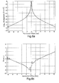
- FIG. 3a and 3b show the magnitude and phase of the total electric field at frequency 0.4Hz.
- the water depth was approximately 270m and the dominant airwave signal is evident at long offsets.
- a "good fit" 1 D model found from inverting the data was used for generating synthetic data and is illustrated by the broken line curves.
- a receiver separation of 600 m is used when comparing the weighted difference-field components with the calculated dE z / dz -field component in Figures 4a and 4b .
- dEz/dz requires one or two offline receivers in addition to two receivers on the towline in order to obtain the components dEy/dy and dE x /dx, respectively.
- the similarity between dE z /dz and the weighted difference field in Figures 4a and 4b demonstrates the main airwave component has been removed by applying weighted differences using conventional inline source-receiver data only.
- the data weights are related to the geometrical spreading factor of the airwave component within the evaluated field component.
Landscapes
- Physics & Mathematics (AREA)
- Electromagnetism (AREA)
- Engineering & Computer Science (AREA)
- Remote Sensing (AREA)
- Life Sciences & Earth Sciences (AREA)
- Environmental & Geological Engineering (AREA)
- Geology (AREA)
- General Life Sciences & Earth Sciences (AREA)
- General Physics & Mathematics (AREA)
- Geophysics (AREA)
- Geophysics And Detection Of Objects (AREA)
- Radar Systems Or Details Thereof (AREA)
Abstract
Description
- The present invention relates to a method of processing controlled source electromagnetic data. The present invention also relates to a program for controlling a computer to perform such a method, a computer readable storage medium containing such a program and a computer containing such a program. The present invention further relates to an apparatus arranged to perform such a method and the use of such a method to reduce airwave contribution.
- In the marine controlled source electromagnetic (CSEM) method for hydrocarbon exploration, also referred to as SeaBed Logging (Ellingsrud et al., 2002; Eidesmo et al., 2002), the so-called airwave may represent a problem for interpreting the subsurface response. The term "airwave" refers to the signal that diffuses vertically upwards from the source to the sea surface, then propagates through the air at the speed of light with no attenuation, before diffusing back down through the seawater column to the sea bottom. In addition, there are the effects of coupling to the subsurface on the source and receiver sides by vertically travelling multiple reflected signals (Nordskag and Amundsen, 2007; Loseth, 2007). Various methods have been proposed to remove the airwave from the total field response, e.g. modelling of the water-layer's airwave effect and then subtracting it from the field data (Lu et al., 2005), applying electromagnetic field decomposition into upgoing and downgoing components (Amundsen et al., 2006), or removing the airwave by weighting inline and broadside data (Loseth and Amundsen, 2007).
- According to a first aspect of the invention, there is provided a method of processing controlled source electromagnetic data, comprising: weighting a plurality of data records in accordance with geometrical spreading of an airwave component; and forming a difference between the weighted data records of at least one pair of the weighted data records.
- For horizontal field component data records responsive to at least one horizontal electric dipole source, the data records may be weighted according to the cube of source-receiver offset.
- For vertical magnetic field data records responsive to at least one horizontal electric dipole source, the data records may be weighted according to the fourth power of source-receiver offset.
- According to a second aspect of the invention, there is provided a method of processing controlled source electromagnetic data, comprising forming a first difference between the data records of each of a plurality of pairs of data records, weighting the first differences in accordance with geometrical spreading of an airwave component, and forming a second difference between the weighted first differences of at least one pair of the weighted first differences.
- For horizontal field component data records responsive to at least one horizontal electric dipole source, the first differences may be weighted according to the fourth power of source-receiver offset.
- For vertical magnetic field data records responsive to at least one horizontal electric dipole source, the first differences may be weighted according to the fifth power of source-receiver offset.
- The method may comprise forming a plurality of differences or second differences to provide a difference field and integrating the difference field.
- According to a third aspect of the invention, there is provided a program for controlling a computer to perform a method according to the first or second aspect of the invention.
- According to a fourth embodiment of the invention, there is provided a computer-readable storage medium containing a program according to the third aspect of the invention.
- According to a fifth aspect of the invention, there is provided a computer containing a program according to the third aspect of the invention.
- According to a sixth aspect of the invention, there is provided an apparatus arranged to perform a method according to the first or second aspect of the invention.
- According to a seventh aspect of the invention, there is provided use of a method according to the first or second aspect of the invention to reduce airwave contribution in data.
- It is thus possible to provide a new technique for removing the airwave signal in CSEM data. An advantage of the new technique is that the conventional inline source-receiver configuration is sufficient. For common source points, the properly rotated (cf. Løseth and Kritski, 2008) time-domain field components are weighted with the geometrical spreading factor of the airwave before the difference field, using two nearby receivers, is calculated. The two receivers preferably have a separation distance above a certain offset in order to produce data above the noise floor. The weighted difference field is scaled by the inverse geometrical spreading factor of the airwave before the derived difference field components are processed in the same way as for standard CSEM data.
- The attenuation or removal of the airwave component may also be done in the common receiver domain. In this case, nearby located pairs of receivers are not required. For both the common receiver and source domain procedures, it may be advantageous to perform the calculations in the time domain.
- Calculation of the difference field by using two nearby receiver responses may help to reduce the amount of correlated noise in the data (Loseth et al., 2008). If the data are weighted before the differences are formed, the reduction of correlated noise is suboptimal. A way of overcoming this can be to form first order differences without weighting the data, and then perform the airwave removal by forming new second order differences using the first order differences. This involves using data from three receivers instead of two.
- Moreover, the resulting field components (at least substantially) void of the airwave may be integrated in order to make the result comparable with the original total field. This also enables estimates of the airwave contribution to the original measured field component.
- The invention will be further described by way of example, with reference to the accompanying drawings, in which:
-
Figure 1 is a diagram illustrating an arrangement for gathering CSEM data; -
Figure 2 is a block diagram illustrating an apparatus for processing the data according to a method constituting an embodiment of the invention; -
Figures 3a and 3b are graphs showing magnitude versus offset (MVO) and phase versus offset (PVO), respectively, for the electric field in the inline direction; -
Figures 4a and 4b are graphs showing MVO and PVO, respectively, with the solid line representing the derived weighted difference-field and the broken line showing the derived dEz /dz field component; -
Figures 5a and 5b are graphs showing MVO and PVO, respectively, with the solid line showing the weighted difference-field components using common source point data and the broken line showing the corresponding data from the synthetic model; and -
Figures 6a and 6b are graphs showing MVO and PVO, respectively, with the solid line showing the weighted difference-field components using common receiver point data and the broken line showing the corresponding data from the synthetic model. - A new technique is provided for removing or reducing the airwave in marine CSEM data. One embodiment uses pairs of receivers or pairs of source points along the towline and processes the horizontal electric and/or magnetic fields in terms of their weighted differences along the towline. The weights are related to the geometrical spreading of the airwave component in the data. This geometrical spreading factor in the horizontal field components equals to a very good approximation the horizontal offset (source-receiver distance) to the power of three. Thus, the horizontal electric and magnetic field components in the common source or receiver domain should be weighted with the horizontal offset to the power of three before the differences along the towline direction of the weighted field components are calculated. The derived difference field components contain almost no airwave signal. In order to remove correlated noise as well as the airwave signal, one could first calculate difference data without weights in the common source domain, and then use the resulting data to perform a second order difference using weights. In this case, the apparent geometrical spreading of the airwave changes and the weights should be equal the horizontal offset to the power of four. Moreover, the weighted differences may be integrated in order to obtain an estimate of the total field void of the airwave. Additionally, the airwave contribution to the total field may also be estimated.
- In the following, II is the dipole moment of a dipole source and β is its azimuthal angle. Variables I describe the propagation of a spectrum of plane-wave components for TE and TM modes. The theoretical background to the technique will be described first.
- For simplicity consider the CSEM experiment in a plane-layered medium. The electromagnetic field components from a horizontal electric dipole source are then (Loseth and Ursin, 2007):


- The expressions for the airwave, in the simple case of constant water conductivity σ, are:



- From the expressions in
equations - For an inline source-receiver configuration let


equation 4 are not influenced by the airwave component. - However, processing the data as described in
equation 4 might not reduce the effect of correlated noise. Thus, we suggest an additional method which removes the correlated noise in a first step and then reduces the effect of the airwave component in a second step. This method requires three nearby receivers in order to form weighted second order differences, say at locations


- We can now calculate differences of the difference data in
equation 5. These second order differences must be weighted by the geometrical spreading factor of the airwave in the expressions inequation 5. Fromequations 

- Neglecting removal of correlated noise, we can also calculate the difference field void of the main airwave component in the common receiver domain. In this case, let


- If a broadside source-receiver configuration is used, it is still possible to use the method of removing the airwave component by calculating weighted difference-field components. In this case the Hz -component can also be evaluated. For the Hz - component, the geometrical spreading factor is proportional to the horizontal offset to the power of four, cf.
equation 2. - The basic relation for removing the airwave for the horizontal field components, written out in terms of differences in
equations 
- Since the dominating offset dependency is in terms of the inverse horizontal offset to the power of three, cf.
equation 2. The expressions in equation 9 (and thus also inequations 4 and 8) can be integrated in order to obtain an expression for the total field void of the airwave:
- In the integration, we ideally need a reference point, i.e. a constant, in order to obtain the optimal estimate of the field without airwave. There are several possibilities for estimating this constant. One option is to assume that the field at large offsets is dominated by the airwave and thus that the remaining field is zero here. A better choice is to estimate the airwave component at a large offset point. Another possibility is to demand that the quantity

- However, when using the procedure for removing the airwave before further data analysis such as inversion or normalization of the fields to a reference field, calculating the constant is not necessary. Thus, an important requirement, when analyzing measured field data that have been pre-processed by removing the airwave, is proper inter-receiver calibration (e.g. by using reciprocity).
-
Figure 1 illustrates a typical arrangement for gathering CSEM data in an offshore location. The seabed is shown at 1 and the sea surface is shown at 2. An exploration vessel orship 3 tows a CSEM source for, for example in the form of a horizontal electric dipole (HED). Thevessel 3 also towsreceivers 5 attached to or forming part of a cable or 'streamer' 6. At least tworeceivers 5 are required although more may be provided as appropriate to the circumstances, and the receivers are disposed in-line with thecable 6 and the towing direction. The spacing between thereceivers 5 is sufficient to provide an adequate signal-to-noise ratio for the acquired data and is typically several hundred metres. - Conversely, a single receiver may be provided and a plurality of spaced in-line sources may be used. Also, a plurality of sources and a plurality of receivers may be used.
- In a typical data acquisition, the
vessel 3 tows thesource 4 and thereceivers 5 along a plurality of paths so as to cover an area of interest. The (or each)source 4 is operated in accordance with conventional techniques and the data received by thereceivers 5 passes along thestreamer 6 to thevessel 3, where it is stored in digital format for subsequent processing, typically at a land-based processing centre. - Each of the
receivers 5 is sensitive to one or more of the Cartesian components of the local electric and/or magnetic field response to thesource 4. The locations of thesource 4 and thereceivers 5 is stored in association with the acquired data so as to allow subsequent mapping of the region of interest, for example in order to determine the presence, location and extent of a hydrocarbon reservoir below theseabed 1. - The acquired data are processed by an apparatus which is typically in the form of a computer and an example of such a computer is shown in
Figure 2 . The computer receives the stored data from the acquisition, as illustrated at 10, at an input interface (II) 11, which receives all inputs including instructions. Theinput interface 11 is connected to a central processing unit (CPU) 12, which is provided with random access memory (RAM) 13 typically providing volatile memory for use during the running of a program, andprogram storage memory 14 illustrated as read-only memory (ROM). The results of processing by theCPU 12 are supplied to an output interface (OI) 15, for example for visualisation or analysis or for further processing in accordance with the requirements of a project. Theprogram memory 14 may receive the program for controlling the computer from a computer-readable storage medium and may include a reader for retrieving the program from the medium. - As described in detail hereinbefore, the computer performs processing, or initial processing, of the CSEM data, which is in the form of a plurality of data records. In particular, the data records are weighted in accordance with the geometrical spreading of an airwave component which, as described hereinbefore, propagates vertically upwardly from the or each
source 4 to thesea surface 2, propagates through the atmosphere along the surface, and then propagates downwardly from the surface to each of thereceivers 5. The difference is then formed between the weighted data records at pairs of different locations, for example different midpoints between the locations of thesource 4 and thereceivers 5 when the data were acquired. In the case where the data records represent horizontal field components responsive to at least oneHED source 4, the data records are weighted according to the cube of the source-receiver offset. In the case of vertical magnetic field data records responsive to at least one HED source, the data records are weighted according to the fourth power of the source-receiver offset. The resulting differences are such that the airwave contribution is greatly attenuated by this processing so that the processed data represent the response with little or no contribution from the airwave. Because water is conductive, the direct wave response travelling directly from the or each source to the or each receiver is attenuated with increasing offset such that, for typical offsets during data acquisition, the contribution of the direct component provides little or insignificant contamination. Thus, the processed data largely represent the response obtained from the electromagnetic field generated by the or eachsource 4 passing into the earth, propagating inside the earth, and returning to the or each receiver. - In a modified form of processing the CSEM data, first differences are formed between pairs of data records without first weighting the records. These first differences are then weighted in accordance with the geometrical spreading of the airwave component and second differences are formed between pairs of the weighted first differences so as to reduce the airwave contribution in the data. For horizontal field component data records responsive to at least one HED source, the first differences are weighted according to the fourth power of the source-receiver offset. For vertical magnetic field data records responsive to at least one HED source, the first differences are weighted according to the fifth power of the source-receiver offset. This modified processing technique may be used, as described hereinbefore, to improve the signal-to-noise ratio of the processed data in addition to the reduction which is achieved in the airwave contribution.
- The data processed in accordance with these techniques may be further processed as required by the specific project. Any suitable processing may be performed, including conventional CSEM processing. These techniques may be used for any application where CSEM exploration is appropriate, such as exploring for new hydrocarbon reserves or monitoring production of known hydrocarbon reserves.
- An example of the use of the present technique is illustrated for real CSEM data offshore Norway using the horizontal electric field for simplicity.
Figures 3a and 3b show the magnitude and phase of the total electric field at frequency 0.4Hz. The water depth was approximately 270m and the dominant airwave signal is evident at long offsets. A "good fit" 1 D model found from inverting the data was used for generating synthetic data and is illustrated by the broken line curves. - For common source point data, a receiver separation of 600 m is used when comparing the weighted difference-field components with the calculated dEz / dz -field component in
Figures 4a and 4b . The dEz/dz-component contains almost no airwave and is calculated using the difference of the Ey component in the crossline direction and the difference of the Ex component along the towline direction according to Gauss' law: dEz / dz = -dEx/dx - dEy/dy. The calculation of dEz/dz requires one or two offline receivers in addition to two receivers on the towline in order to obtain the components dEy/dy and dEx/dx, respectively. The similarity between dEz/dz and the weighted difference field inFigures 4a and 4b demonstrates the main airwave component has been removed by applying weighted differences using conventional inline source-receiver data only. - Finally we compare calculation of the difference field for common source points (CSP) and common receiver points (CRP) in
Figures 5a, 5b and6a, 6b , respectively. The difference field in the CRP domain gives better results than the difference field in the CSP domain for this data set. This is explained by inaccuracies in the inter-receiver calibration of the measured field components. Thus, to utilize the method of weighted differences in a proper manner in the CSP domain, the field measurements at each receiver should be accurately calibrated. - Thus, by calculating a weighted difference field using data from two nearby receivers or one receiver and nearby source points, it is possible substantially to remove the main airwave component in marine CSEM data. The data weights are related to the geometrical spreading factor of the airwave component within the evaluated field component.
-
- Amundsen, L., Løseth, L. 0., Mittet, R., Ellingsrud, S., and Ursin, B., 2006, Decomposition of electromagnetic fields into upgoing and downgoing components: Geophysics, 71, G211-G223.
- Eidesmo, T., Ellingsrud, S., MacGregor, L. M., Constable, S. C., Sinha, M. C., Johansen, S., Kong, F. N., and Westerdahl, H., 2002, SeaBed Logging (SBL), a new method for remote and direct identification of hydrocarbon filled layers in deepwater areas using controlled source electromagnetic sounding: First Break, 20, 144-152.
- Ellingsrud, S., Eidesmo, T., Sinha, M. C., MacGregor, L. M., and Constable, S. C., 2002, Remote sensing of hydrocarbon layers by SeaBed Legging (SBL): Results from a cruise offshore Angola: Leading Edge, 20, 972-982.
- Løseth, L. 0., 2007, Modelling of Controlled Source Electromagnetic Data. PhD Thesis, NTNU.
- Løseth, L. O. and Amundsen, L., 2007, Removal of air-response by weighting inline and broadside CSEM/SBL data: 77th SEG Conference, San Antonio.
- Løseth, L. O. and Ursin, B., 2007, Electromagnetic fields in planarly layered anisotropic media: Geophysical Journal International, 170, 44-80.
- Lu, X., Srnka, L. J., and Carazzone, J. J., 2005, Method for removing air wave effect from offshore frequency domain controlled-source electromagnetic data:
W02005/010560 . - Nordskag, J. and Amundsen, L., 2007, Asymptotic airwave modeling for marine controlled source electromagnetic surveying: Geophysics. 72. F249-F255.
Claims (12)
- A method of processing controlled source electromagnetic data, comprising forming a first difference between the data records of each of a plurality of pairs of data records, weighting the first differences in accordance with geometrical spreading of an airwave component, and forming a second difference between the weighted first differences of at least one pair of the weighted first differences.
- A method as claimed in claim 1, in which, for horizontal field component data records responsive to at least one horizontal electric dipole source, the first differences are weighted according to the fourth power of source-receiver offset.
- A method as claimed in claim 1, in which, for vertical magnetic field data records responsive to at least one horizontal electric dipole source, the first differences are weighted according to the fifth power of source-receiver offset.
- A method of processing controlled source electromagnetic data, comprising weighting a plurality of data records in accordance with geometrical spreading of an airwave component and forming a difference between the weighted data records of at least one pair of the weighted data records.
- A method as claimed in claim 4, in which, for horizontal field component data records responsive to at least one horizontal electric dipole source, the data records are weighted according to the cube of source-receiver offset.
- A method as claimed in claim 4, in which, for vertical magnetic field data records responsive to at least one horizontal electric dipole source, the data records are weighted according to the fourth power of source-receiver offset.
- A method as claimed in any one of the preceding claims, comprising forming a plurality of differences or second differences to provide a difference field and integrating the difference field.
- A program for controlling a computer to perform a method as claimed in any one of the preceding claims.
- A computer-readable storage medium containing a program as claimed in claim 8.
- A computer containing a program as claimed in claim 8.
- An apparatus arranged to perform a method as claimed in any one of claims 1 to 7.
- Use of a method as claimed in any one of claims 1 to 7 to reduce airwave contribution in the data.
Applications Claiming Priority (2)
| Application Number | Priority Date | Filing Date | Title |
|---|---|---|---|
| GBGB0900906.9A GB0900906D0 (en) | 2009-01-20 | 2009-01-20 | Removing or reducing the airwave in CSEM data by using weighted field differences |
| EP10705565.9A EP2382491B1 (en) | 2009-01-20 | 2010-01-19 | Method of and apparatus for processing csem data, program, storage medium and computer |
Related Parent Applications (2)
| Application Number | Title | Priority Date | Filing Date |
|---|---|---|---|
| EP10705565.9A Division-Into EP2382491B1 (en) | 2009-01-20 | 2010-01-19 | Method of and apparatus for processing csem data, program, storage medium and computer |
| EP10705565.9A Division EP2382491B1 (en) | 2009-01-20 | 2010-01-19 | Method of and apparatus for processing csem data, program, storage medium and computer |
Publications (3)
| Publication Number | Publication Date |
|---|---|
| EP2735889A2 true EP2735889A2 (en) | 2014-05-28 |
| EP2735889A3 EP2735889A3 (en) | 2014-08-13 |
| EP2735889B1 EP2735889B1 (en) | 2018-04-04 |
Family
ID=40446062
Family Applications (2)
| Application Number | Title | Priority Date | Filing Date |
|---|---|---|---|
| EP10705565.9A Not-in-force EP2382491B1 (en) | 2009-01-20 | 2010-01-19 | Method of and apparatus for processing csem data, program, storage medium and computer |
| EP14156390.8A Not-in-force EP2735889B1 (en) | 2009-01-20 | 2010-01-19 | Method for Processing CSEM Data, Program, Storage Medium and Use of Method |
Family Applications Before (1)
| Application Number | Title | Priority Date | Filing Date |
|---|---|---|---|
| EP10705565.9A Not-in-force EP2382491B1 (en) | 2009-01-20 | 2010-01-19 | Method of and apparatus for processing csem data, program, storage medium and computer |
Country Status (4)
| Country | Link |
|---|---|
| US (1) | US10677951B2 (en) |
| EP (2) | EP2382491B1 (en) |
| GB (1) | GB0900906D0 (en) |
| WO (1) | WO2010084117A1 (en) |
Families Citing this family (4)
| Publication number | Priority date | Publication date | Assignee | Title |
|---|---|---|---|---|
| GB0616870D0 (en) | 2006-08-25 | 2006-10-04 | Mtem Ltd | Improvements In Marine EM Exploration |
| GB0702661D0 (en) | 2007-02-12 | 2007-03-21 | Mtem Ltd | Improvements in marine EM exploration |
| US8258791B2 (en) * | 2009-01-27 | 2012-09-04 | Mtem Ltd. | Method for subsurface electromagnetic surveying using two or more simultaneously actuated electromagnetic sources to impart electromagnetic signals into a subsurface formation and thereby determining a formation response to each signal |
| JP6098446B2 (en) * | 2013-09-04 | 2017-03-22 | トヨタ自動車株式会社 | Engine control device |
Family Cites Families (6)
| Publication number | Priority date | Publication date | Assignee | Title |
|---|---|---|---|---|
| US5657756A (en) * | 1995-06-07 | 1997-08-19 | Ctf Systems Inc. | Method and systems for obtaining higher order gradiometer measurements with lower order gradiometers |
| NO326957B1 (en) | 2006-02-13 | 2009-03-23 | Norsk Hydro As | Electromagnetic method on shallow water using controlled source |
| EP1991886A4 (en) | 2006-02-21 | 2012-07-04 | Exxonmobil Upstream Res Co | Method for electromagnetic air-wave suppression by active cancellation and shielding |
| US7860655B2 (en) | 2006-07-14 | 2010-12-28 | Westerngeco L.L.C. | Electromagnetically detecting thin resistive bodies in shallow water and terrestrial environments |
| GB0623279D0 (en) | 2006-11-22 | 2007-01-03 | Statoil Asa | Air wave modeling for MCSEM/SBL surveying |
| GB0706659D0 (en) | 2007-04-05 | 2007-05-16 | Statoil Asa | Reduction of airwave contribution in marine electromagnetic data |
-
2009
- 2009-01-20 GB GBGB0900906.9A patent/GB0900906D0/en not_active Ceased
-
2010
- 2010-01-19 WO PCT/EP2010/050589 patent/WO2010084117A1/en not_active Ceased
- 2010-01-19 EP EP10705565.9A patent/EP2382491B1/en not_active Not-in-force
- 2010-01-19 EP EP14156390.8A patent/EP2735889B1/en not_active Not-in-force
- 2010-01-19 US US13/145,277 patent/US10677951B2/en not_active Expired - Fee Related
Also Published As
| Publication number | Publication date |
|---|---|
| GB0900906D0 (en) | 2009-03-04 |
| EP2382491B1 (en) | 2018-11-07 |
| US20120011130A1 (en) | 2012-01-12 |
| EP2382491A1 (en) | 2011-11-02 |
| EP2735889B1 (en) | 2018-04-04 |
| EP2735889A3 (en) | 2014-08-13 |
| US10677951B2 (en) | 2020-06-09 |
| WO2010084117A1 (en) | 2010-07-29 |
Similar Documents
| Publication | Publication Date | Title |
|---|---|---|
| US7542851B2 (en) | Electromagnetic surveying for hydrocarbon reservoirs | |
| Myer et al. | Marine CSEM of the Scarborough gas field, Part 1: Experimental design and data uncertainty | |
| US7880469B2 (en) | Surveying method using an arrangement of plural signal sources | |
| CA2657475C (en) | Geophysical prospecting with reduced air wave noise | |
| US20080150538A1 (en) | Electromagnetic surveying for resistive or conductive bodies | |
| CN102428391A (en) | Method and apparatus for offshore hydrocarbon electromagnetic prospecting based on total magnetic field measurements | |
| US20120123683A1 (en) | Csem survey method | |
| Constable et al. | Marine controlled-source electromagnetic of the Scarborough gas field—Part 3: Multicomponent 2D magnetotelluric/controlled-source electromagnetic inversions | |
| RU2423728C2 (en) | Method and device for processing electromagnetic exploration data | |
| EP2735889B1 (en) | Method for Processing CSEM Data, Program, Storage Medium and Use of Method | |
| Løseth et al. | A solution to the airwave-removal problem in shallow-water marine EM | |
| US9069096B2 (en) | Method of processing marine CSEM data | |
| US7949470B2 (en) | Processing measurement data in a deep water application | |
| US20140191760A1 (en) | Method and apparatus for suppression of the airwave in subsea exploration | |
| King et al. | CUESI: A Near Seafloor Controlled-Source Electromagnetic System for Shallow Seabed Characterization | |
| Constable et al. | Case History Marine controlled-source electromagnetic of the Scarborough gas field—Part 3: Multicomponent 2D magnetotelluric/controlled-source electromagnetic inversions | |
| Jegen et al. | Quantification of marine sulfide deposits using marine electromagnetic methods | |
| Morten et al. | Sub-basalt imaging using broadside CSEM | |
| Ellingsrud et al. | CSEM: a fast growing technology |
Legal Events
| Date | Code | Title | Description |
|---|---|---|---|
| PUAI | Public reference made under article 153(3) epc to a published international application that has entered the european phase |
Free format text: ORIGINAL CODE: 0009012 |
|
| 17P | Request for examination filed |
Effective date: 20140224 |
|
| AC | Divisional application: reference to earlier application |
Ref document number: 2382491 Country of ref document: EP Kind code of ref document: P |
|
| AK | Designated contracting states |
Kind code of ref document: A2 Designated state(s): AT BE BG CH CY CZ DE DK EE ES FI FR GB GR HR HU IE IS IT LI LT LU LV MC MK MT NL NO PL PT RO SE SI SK SM TR |
|
| PUAL | Search report despatched |
Free format text: ORIGINAL CODE: 0009013 |
|
| AK | Designated contracting states |
Kind code of ref document: A3 Designated state(s): AT BE BG CH CY CZ DE DK EE ES FI FR GB GR HR HU IE IS IT LI LT LU LV MC MK MT NL NO PL PT RO SE SI SK SM TR |
|
| RIC1 | Information provided on ipc code assigned before grant |
Ipc: G01V 3/08 20060101AFI20140710BHEP |
|
| GRAP | Despatch of communication of intention to grant a patent |
Free format text: ORIGINAL CODE: EPIDOSNIGR1 |
|
| STAA | Information on the status of an ep patent application or granted ep patent |
Free format text: STATUS: GRANT OF PATENT IS INTENDED |
|
| INTG | Intention to grant announced |
Effective date: 20171011 |
|
| GRAS | Grant fee paid |
Free format text: ORIGINAL CODE: EPIDOSNIGR3 |
|
| GRAA | (expected) grant |
Free format text: ORIGINAL CODE: 0009210 |
|
| STAA | Information on the status of an ep patent application or granted ep patent |
Free format text: STATUS: THE PATENT HAS BEEN GRANTED |
|
| AC | Divisional application: reference to earlier application |
Ref document number: 2382491 Country of ref document: EP Kind code of ref document: P |
|
| AK | Designated contracting states |
Kind code of ref document: B1 Designated state(s): AT BE BG CH CY CZ DE DK EE ES FI FR GB GR HR HU IE IS IT LI LT LU LV MC MK MT NL NO PL PT RO SE SI SK SM TR |
|
| REG | Reference to a national code |
Ref country code: GB Ref legal event code: FG4D |
|
| REG | Reference to a national code |
Ref country code: CH Ref legal event code: EP |
|
| REG | Reference to a national code |
Ref country code: AT Ref legal event code: REF Ref document number: 986173 Country of ref document: AT Kind code of ref document: T Effective date: 20180415 |
|
| REG | Reference to a national code |
Ref country code: IE Ref legal event code: FG4D |
|
| REG | Reference to a national code |
Ref country code: DE Ref legal event code: R096 Ref document number: 602010049775 Country of ref document: DE |
|
| REG | Reference to a national code |
Ref country code: NL Ref legal event code: MP Effective date: 20180404 |
|
| REG | Reference to a national code |
Ref country code: LT Ref legal event code: MG4D |
|
| REG | Reference to a national code |
Ref country code: NO Ref legal event code: T2 Effective date: 20180404 |
|
| PG25 | Lapsed in a contracting state [announced via postgrant information from national office to epo] |
Ref country code: NL Free format text: LAPSE BECAUSE OF FAILURE TO SUBMIT A TRANSLATION OF THE DESCRIPTION OR TO PAY THE FEE WITHIN THE PRESCRIBED TIME-LIMIT Effective date: 20180404 |
|
| PG25 | Lapsed in a contracting state [announced via postgrant information from national office to epo] |
Ref country code: ES Free format text: LAPSE BECAUSE OF FAILURE TO SUBMIT A TRANSLATION OF THE DESCRIPTION OR TO PAY THE FEE WITHIN THE PRESCRIBED TIME-LIMIT Effective date: 20180404 Ref country code: SE Free format text: LAPSE BECAUSE OF FAILURE TO SUBMIT A TRANSLATION OF THE DESCRIPTION OR TO PAY THE FEE WITHIN THE PRESCRIBED TIME-LIMIT Effective date: 20180404 Ref country code: BG Free format text: LAPSE BECAUSE OF FAILURE TO SUBMIT A TRANSLATION OF THE DESCRIPTION OR TO PAY THE FEE WITHIN THE PRESCRIBED TIME-LIMIT Effective date: 20180704 Ref country code: PL Free format text: LAPSE BECAUSE OF FAILURE TO SUBMIT A TRANSLATION OF THE DESCRIPTION OR TO PAY THE FEE WITHIN THE PRESCRIBED TIME-LIMIT Effective date: 20180404 Ref country code: FI Free format text: LAPSE BECAUSE OF FAILURE TO SUBMIT A TRANSLATION OF THE DESCRIPTION OR TO PAY THE FEE WITHIN THE PRESCRIBED TIME-LIMIT Effective date: 20180404 Ref country code: LT Free format text: LAPSE BECAUSE OF FAILURE TO SUBMIT A TRANSLATION OF THE DESCRIPTION OR TO PAY THE FEE WITHIN THE PRESCRIBED TIME-LIMIT Effective date: 20180404 |
|
| PG25 | Lapsed in a contracting state [announced via postgrant information from national office to epo] |
Ref country code: LV Free format text: LAPSE BECAUSE OF FAILURE TO SUBMIT A TRANSLATION OF THE DESCRIPTION OR TO PAY THE FEE WITHIN THE PRESCRIBED TIME-LIMIT Effective date: 20180404 Ref country code: HR Free format text: LAPSE BECAUSE OF FAILURE TO SUBMIT A TRANSLATION OF THE DESCRIPTION OR TO PAY THE FEE WITHIN THE PRESCRIBED TIME-LIMIT Effective date: 20180404 Ref country code: GR Free format text: LAPSE BECAUSE OF FAILURE TO SUBMIT A TRANSLATION OF THE DESCRIPTION OR TO PAY THE FEE WITHIN THE PRESCRIBED TIME-LIMIT Effective date: 20180705 |
|
| REG | Reference to a national code |
Ref country code: AT Ref legal event code: MK05 Ref document number: 986173 Country of ref document: AT Kind code of ref document: T Effective date: 20180404 |
|
| PG25 | Lapsed in a contracting state [announced via postgrant information from national office to epo] |
Ref country code: PT Free format text: LAPSE BECAUSE OF FAILURE TO SUBMIT A TRANSLATION OF THE DESCRIPTION OR TO PAY THE FEE WITHIN THE PRESCRIBED TIME-LIMIT Effective date: 20180806 |
|
| REG | Reference to a national code |
Ref country code: DE Ref legal event code: R097 Ref document number: 602010049775 Country of ref document: DE |
|
| PG25 | Lapsed in a contracting state [announced via postgrant information from national office to epo] |
Ref country code: RO Free format text: LAPSE BECAUSE OF FAILURE TO SUBMIT A TRANSLATION OF THE DESCRIPTION OR TO PAY THE FEE WITHIN THE PRESCRIBED TIME-LIMIT Effective date: 20180404 Ref country code: CZ Free format text: LAPSE BECAUSE OF FAILURE TO SUBMIT A TRANSLATION OF THE DESCRIPTION OR TO PAY THE FEE WITHIN THE PRESCRIBED TIME-LIMIT Effective date: 20180404 Ref country code: SK Free format text: LAPSE BECAUSE OF FAILURE TO SUBMIT A TRANSLATION OF THE DESCRIPTION OR TO PAY THE FEE WITHIN THE PRESCRIBED TIME-LIMIT Effective date: 20180404 Ref country code: EE Free format text: LAPSE BECAUSE OF FAILURE TO SUBMIT A TRANSLATION OF THE DESCRIPTION OR TO PAY THE FEE WITHIN THE PRESCRIBED TIME-LIMIT Effective date: 20180404 Ref country code: DK Free format text: LAPSE BECAUSE OF FAILURE TO SUBMIT A TRANSLATION OF THE DESCRIPTION OR TO PAY THE FEE WITHIN THE PRESCRIBED TIME-LIMIT Effective date: 20180404 Ref country code: AT Free format text: LAPSE BECAUSE OF FAILURE TO SUBMIT A TRANSLATION OF THE DESCRIPTION OR TO PAY THE FEE WITHIN THE PRESCRIBED TIME-LIMIT Effective date: 20180404 |
|
| PLBE | No opposition filed within time limit |
Free format text: ORIGINAL CODE: 0009261 |
|
| STAA | Information on the status of an ep patent application or granted ep patent |
Free format text: STATUS: NO OPPOSITION FILED WITHIN TIME LIMIT |
|
| PG25 | Lapsed in a contracting state [announced via postgrant information from national office to epo] |
Ref country code: IT Free format text: LAPSE BECAUSE OF FAILURE TO SUBMIT A TRANSLATION OF THE DESCRIPTION OR TO PAY THE FEE WITHIN THE PRESCRIBED TIME-LIMIT Effective date: 20180404 Ref country code: SM Free format text: LAPSE BECAUSE OF FAILURE TO SUBMIT A TRANSLATION OF THE DESCRIPTION OR TO PAY THE FEE WITHIN THE PRESCRIBED TIME-LIMIT Effective date: 20180404 |
|
| 26N | No opposition filed |
Effective date: 20190107 |
|
| PG25 | Lapsed in a contracting state [announced via postgrant information from national office to epo] |
Ref country code: SI Free format text: LAPSE BECAUSE OF FAILURE TO SUBMIT A TRANSLATION OF THE DESCRIPTION OR TO PAY THE FEE WITHIN THE PRESCRIBED TIME-LIMIT Effective date: 20180404 |
|
| REG | Reference to a national code |
Ref country code: DE Ref legal event code: R119 Ref document number: 602010049775 Country of ref document: DE |
|
| PG25 | Lapsed in a contracting state [announced via postgrant information from national office to epo] |
Ref country code: MC Free format text: LAPSE BECAUSE OF FAILURE TO SUBMIT A TRANSLATION OF THE DESCRIPTION OR TO PAY THE FEE WITHIN THE PRESCRIBED TIME-LIMIT Effective date: 20180404 |
|
| REG | Reference to a national code |
Ref country code: CH Ref legal event code: PL |
|
| PG25 | Lapsed in a contracting state [announced via postgrant information from national office to epo] |
Ref country code: LU Free format text: LAPSE BECAUSE OF NON-PAYMENT OF DUE FEES Effective date: 20190119 |
|
| REG | Reference to a national code |
Ref country code: BE Ref legal event code: MM Effective date: 20190131 |
|
| REG | Reference to a national code |
Ref country code: IE Ref legal event code: MM4A |
|
| PG25 | Lapsed in a contracting state [announced via postgrant information from national office to epo] |
Ref country code: FR Free format text: LAPSE BECAUSE OF NON-PAYMENT OF DUE FEES Effective date: 20190131 Ref country code: DE Free format text: LAPSE BECAUSE OF NON-PAYMENT OF DUE FEES Effective date: 20190801 |
|
| PG25 | Lapsed in a contracting state [announced via postgrant information from national office to epo] |
Ref country code: BE Free format text: LAPSE BECAUSE OF NON-PAYMENT OF DUE FEES Effective date: 20190131 |
|
| PG25 | Lapsed in a contracting state [announced via postgrant information from national office to epo] |
Ref country code: LI Free format text: LAPSE BECAUSE OF NON-PAYMENT OF DUE FEES Effective date: 20190131 Ref country code: CH Free format text: LAPSE BECAUSE OF NON-PAYMENT OF DUE FEES Effective date: 20190131 |
|
| PG25 | Lapsed in a contracting state [announced via postgrant information from national office to epo] |
Ref country code: IE Free format text: LAPSE BECAUSE OF NON-PAYMENT OF DUE FEES Effective date: 20190119 |
|
| PG25 | Lapsed in a contracting state [announced via postgrant information from national office to epo] |
Ref country code: TR Free format text: LAPSE BECAUSE OF FAILURE TO SUBMIT A TRANSLATION OF THE DESCRIPTION OR TO PAY THE FEE WITHIN THE PRESCRIBED TIME-LIMIT Effective date: 20180404 |
|
| PGFP | Annual fee paid to national office [announced via postgrant information from national office to epo] |
Ref country code: GB Payment date: 20200129 Year of fee payment: 11 Ref country code: NO Payment date: 20200123 Year of fee payment: 11 |
|
| PG25 | Lapsed in a contracting state [announced via postgrant information from national office to epo] |
Ref country code: MT Free format text: LAPSE BECAUSE OF NON-PAYMENT OF DUE FEES Effective date: 20190119 |
|
| PG25 | Lapsed in a contracting state [announced via postgrant information from national office to epo] |
Ref country code: CY Free format text: LAPSE BECAUSE OF FAILURE TO SUBMIT A TRANSLATION OF THE DESCRIPTION OR TO PAY THE FEE WITHIN THE PRESCRIBED TIME-LIMIT Effective date: 20180404 |
|
| PG25 | Lapsed in a contracting state [announced via postgrant information from national office to epo] |
Ref country code: IS Free format text: LAPSE BECAUSE OF FAILURE TO SUBMIT A TRANSLATION OF THE DESCRIPTION OR TO PAY THE FEE WITHIN THE PRESCRIBED TIME-LIMIT Effective date: 20180804 |
|
| PG25 | Lapsed in a contracting state [announced via postgrant information from national office to epo] |
Ref country code: HU Free format text: LAPSE BECAUSE OF FAILURE TO SUBMIT A TRANSLATION OF THE DESCRIPTION OR TO PAY THE FEE WITHIN THE PRESCRIBED TIME-LIMIT; INVALID AB INITIO Effective date: 20100119 |
|
| REG | Reference to a national code |
Ref country code: NO Ref legal event code: MMEP |
|
| GBPC | Gb: european patent ceased through non-payment of renewal fee |
Effective date: 20210119 |
|
| PG25 | Lapsed in a contracting state [announced via postgrant information from national office to epo] |
Ref country code: NO Free format text: LAPSE BECAUSE OF NON-PAYMENT OF DUE FEES Effective date: 20210131 Ref country code: GB Free format text: LAPSE BECAUSE OF NON-PAYMENT OF DUE FEES Effective date: 20210119 |
|
| PG25 | Lapsed in a contracting state [announced via postgrant information from national office to epo] |
Ref country code: MK Free format text: LAPSE BECAUSE OF FAILURE TO SUBMIT A TRANSLATION OF THE DESCRIPTION OR TO PAY THE FEE WITHIN THE PRESCRIBED TIME-LIMIT Effective date: 20180404 |