EP2735722A1 - Fuel system for an excavator - Google Patents
Fuel system for an excavator Download PDFInfo
- Publication number
- EP2735722A1 EP2735722A1 EP20110869344 EP11869344A EP2735722A1 EP 2735722 A1 EP2735722 A1 EP 2735722A1 EP 20110869344 EP20110869344 EP 20110869344 EP 11869344 A EP11869344 A EP 11869344A EP 2735722 A1 EP2735722 A1 EP 2735722A1
- Authority
- EP
- European Patent Office
- Prior art keywords
- fuel
- engine
- filter
- injector
- return line
- Prior art date
- Legal status (The legal status is an assumption and is not a legal conclusion. Google has not performed a legal analysis and makes no representation as to the accuracy of the status listed.)
- Granted
Links
- 239000000446 fuel Substances 0.000 title claims abstract description 120
- 238000002347 injection Methods 0.000 claims abstract description 18
- 239000007924 injection Substances 0.000 claims abstract description 18
- 238000002485 combustion reaction Methods 0.000 claims abstract description 11
- XLYOFNOQVPJJNP-UHFFFAOYSA-N water Substances O XLYOFNOQVPJJNP-UHFFFAOYSA-N 0.000 claims description 18
- 239000000126 substance Substances 0.000 claims description 7
- 238000001514 detection method Methods 0.000 claims description 4
- 239000002828 fuel tank Substances 0.000 abstract description 22
- 239000012223 aqueous fraction Substances 0.000 abstract 3
- 239000010763 heavy fuel oil Substances 0.000 abstract 3
- 239000000463 material Substances 0.000 abstract 2
- 238000007599 discharging Methods 0.000 abstract 1
- 238000005086 pumping Methods 0.000 description 3
- 238000010276 construction Methods 0.000 description 1
- 230000000694 effects Effects 0.000 description 1
- 238000012423 maintenance Methods 0.000 description 1
- 238000012986 modification Methods 0.000 description 1
- 230000004048 modification Effects 0.000 description 1
- 239000000243 solution Substances 0.000 description 1
Images
Classifications
-
- F—MECHANICAL ENGINEERING; LIGHTING; HEATING; WEAPONS; BLASTING
- F02—COMBUSTION ENGINES; HOT-GAS OR COMBUSTION-PRODUCT ENGINE PLANTS
- F02M—SUPPLYING COMBUSTION ENGINES IN GENERAL WITH COMBUSTIBLE MIXTURES OR CONSTITUENTS THEREOF
- F02M37/00—Apparatus or systems for feeding liquid fuel from storage containers to carburettors or fuel-injection apparatus; Arrangements for purifying liquid fuel specially adapted for, or arranged on, internal-combustion engines
- F02M37/22—Arrangements for purifying liquid fuel specially adapted for, or arranged on, internal-combustion engines, e.g. arrangements in the feeding system
- F02M37/32—Arrangements for purifying liquid fuel specially adapted for, or arranged on, internal-combustion engines, e.g. arrangements in the feeding system characterised by filters or filter arrangements
- F02M37/44—Filters structurally associated with pumps
-
- E—FIXED CONSTRUCTIONS
- E02—HYDRAULIC ENGINEERING; FOUNDATIONS; SOIL SHIFTING
- E02F—DREDGING; SOIL-SHIFTING
- E02F9/00—Component parts of dredgers or soil-shifting machines, not restricted to one of the kinds covered by groups E02F3/00 - E02F7/00
- E02F9/20—Drives; Control devices
- E02F9/2058—Electric or electro-mechanical or mechanical control devices of vehicle sub-units
- E02F9/2062—Control of propulsion units
- E02F9/2066—Control of propulsion units of the type combustion engines
-
- F—MECHANICAL ENGINEERING; LIGHTING; HEATING; WEAPONS; BLASTING
- F02—COMBUSTION ENGINES; HOT-GAS OR COMBUSTION-PRODUCT ENGINE PLANTS
- F02D—CONTROLLING COMBUSTION ENGINES
- F02D33/00—Controlling delivery of fuel or combustion-air, not otherwise provided for
- F02D33/003—Controlling the feeding of liquid fuel from storage containers to carburettors or fuel-injection apparatus ; Failure or leakage prevention; Diagnosis or detection of failure; Arrangement of sensors in the fuel system; Electric wiring; Electrostatic discharge
- F02D33/006—Controlling the feeding of liquid fuel from storage containers to carburettors or fuel-injection apparatus ; Failure or leakage prevention; Diagnosis or detection of failure; Arrangement of sensors in the fuel system; Electric wiring; Electrostatic discharge depending on engine operating conditions, e.g. start, stop or ambient conditions
-
- F—MECHANICAL ENGINEERING; LIGHTING; HEATING; WEAPONS; BLASTING
- F02—COMBUSTION ENGINES; HOT-GAS OR COMBUSTION-PRODUCT ENGINE PLANTS
- F02M—SUPPLYING COMBUSTION ENGINES IN GENERAL WITH COMBUSTIBLE MIXTURES OR CONSTITUENTS THEREOF
- F02M35/00—Combustion-air cleaners, air intakes, intake silencers, or induction systems specially adapted for, or arranged on, internal-combustion engines
- F02M35/10—Air intakes; Induction systems
- F02M35/10209—Fluid connections to the air intake system; their arrangement of pipes, valves or the like
- F02M35/10216—Fuel injectors; Fuel pipes or rails; Fuel pumps or pressure regulators
-
- F—MECHANICAL ENGINEERING; LIGHTING; HEATING; WEAPONS; BLASTING
- F02—COMBUSTION ENGINES; HOT-GAS OR COMBUSTION-PRODUCT ENGINE PLANTS
- F02M—SUPPLYING COMBUSTION ENGINES IN GENERAL WITH COMBUSTIBLE MIXTURES OR CONSTITUENTS THEREOF
- F02M37/00—Apparatus or systems for feeding liquid fuel from storage containers to carburettors or fuel-injection apparatus; Arrangements for purifying liquid fuel specially adapted for, or arranged on, internal-combustion engines
- F02M37/0011—Constructional details; Manufacturing or assembly of elements of fuel systems; Materials therefor
- F02M37/0023—Valves in the fuel supply and return system
- F02M37/0029—Pressure regulator in the low pressure fuel system
-
- F—MECHANICAL ENGINEERING; LIGHTING; HEATING; WEAPONS; BLASTING
- F02—COMBUSTION ENGINES; HOT-GAS OR COMBUSTION-PRODUCT ENGINE PLANTS
- F02M—SUPPLYING COMBUSTION ENGINES IN GENERAL WITH COMBUSTIBLE MIXTURES OR CONSTITUENTS THEREOF
- F02M37/00—Apparatus or systems for feeding liquid fuel from storage containers to carburettors or fuel-injection apparatus; Arrangements for purifying liquid fuel specially adapted for, or arranged on, internal-combustion engines
- F02M37/0047—Layout or arrangement of systems for feeding fuel
- F02M37/0052—Details on the fuel return circuit; Arrangement of pressure regulators
-
- F—MECHANICAL ENGINEERING; LIGHTING; HEATING; WEAPONS; BLASTING
- F02—COMBUSTION ENGINES; HOT-GAS OR COMBUSTION-PRODUCT ENGINE PLANTS
- F02M—SUPPLYING COMBUSTION ENGINES IN GENERAL WITH COMBUSTIBLE MIXTURES OR CONSTITUENTS THEREOF
- F02M37/00—Apparatus or systems for feeding liquid fuel from storage containers to carburettors or fuel-injection apparatus; Arrangements for purifying liquid fuel specially adapted for, or arranged on, internal-combustion engines
- F02M37/04—Feeding by means of driven pumps
- F02M37/16—Feeding by means of driven pumps characterised by provision of personally-, e.g. manually-, operated pumps
-
- F—MECHANICAL ENGINEERING; LIGHTING; HEATING; WEAPONS; BLASTING
- F02—COMBUSTION ENGINES; HOT-GAS OR COMBUSTION-PRODUCT ENGINE PLANTS
- F02M—SUPPLYING COMBUSTION ENGINES IN GENERAL WITH COMBUSTIBLE MIXTURES OR CONSTITUENTS THEREOF
- F02M37/00—Apparatus or systems for feeding liquid fuel from storage containers to carburettors or fuel-injection apparatus; Arrangements for purifying liquid fuel specially adapted for, or arranged on, internal-combustion engines
- F02M37/22—Arrangements for purifying liquid fuel specially adapted for, or arranged on, internal-combustion engines, e.g. arrangements in the feeding system
- F02M37/24—Arrangements for purifying liquid fuel specially adapted for, or arranged on, internal-combustion engines, e.g. arrangements in the feeding system characterised by water separating means
-
- F—MECHANICAL ENGINEERING; LIGHTING; HEATING; WEAPONS; BLASTING
- F02—COMBUSTION ENGINES; HOT-GAS OR COMBUSTION-PRODUCT ENGINE PLANTS
- F02D—CONTROLLING COMBUSTION ENGINES
- F02D2200/00—Input parameters for engine control
- F02D2200/02—Input parameters for engine control the parameters being related to the engine
- F02D2200/06—Fuel or fuel supply system parameters
- F02D2200/0602—Fuel pressure
-
- F—MECHANICAL ENGINEERING; LIGHTING; HEATING; WEAPONS; BLASTING
- F02—COMBUSTION ENGINES; HOT-GAS OR COMBUSTION-PRODUCT ENGINE PLANTS
- F02M—SUPPLYING COMBUSTION ENGINES IN GENERAL WITH COMBUSTIBLE MIXTURES OR CONSTITUENTS THEREOF
- F02M2200/00—Details of fuel-injection apparatus, not otherwise provided for
- F02M2200/60—Fuel-injection apparatus having means for facilitating the starting of engines, e.g. with valves or fuel passages for keeping residual pressure in common rails
-
- F—MECHANICAL ENGINEERING; LIGHTING; HEATING; WEAPONS; BLASTING
- F02—COMBUSTION ENGINES; HOT-GAS OR COMBUSTION-PRODUCT ENGINE PLANTS
- F02M—SUPPLYING COMBUSTION ENGINES IN GENERAL WITH COMBUSTIBLE MIXTURES OR CONSTITUENTS THEREOF
- F02M37/00—Apparatus or systems for feeding liquid fuel from storage containers to carburettors or fuel-injection apparatus; Arrangements for purifying liquid fuel specially adapted for, or arranged on, internal-combustion engines
- F02M37/22—Arrangements for purifying liquid fuel specially adapted for, or arranged on, internal-combustion engines, e.g. arrangements in the feeding system
- F02M37/32—Arrangements for purifying liquid fuel specially adapted for, or arranged on, internal-combustion engines, e.g. arrangements in the feeding system characterised by filters or filter arrangements
-
- F—MECHANICAL ENGINEERING; LIGHTING; HEATING; WEAPONS; BLASTING
- F02—COMBUSTION ENGINES; HOT-GAS OR COMBUSTION-PRODUCT ENGINE PLANTS
- F02M—SUPPLYING COMBUSTION ENGINES IN GENERAL WITH COMBUSTIBLE MIXTURES OR CONSTITUENTS THEREOF
- F02M55/00—Fuel-injection apparatus characterised by their fuel conduits or their venting means; Arrangements of conduits between fuel tank and pump F02M37/00
- F02M55/004—Joints; Sealings
- F02M55/005—Joints; Sealings for high pressure conduits, e.g. connected to pump outlet or to injector inlet
-
- F—MECHANICAL ENGINEERING; LIGHTING; HEATING; WEAPONS; BLASTING
- F02—COMBUSTION ENGINES; HOT-GAS OR COMBUSTION-PRODUCT ENGINE PLANTS
- F02M—SUPPLYING COMBUSTION ENGINES IN GENERAL WITH COMBUSTIBLE MIXTURES OR CONSTITUENTS THEREOF
- F02M55/00—Fuel-injection apparatus characterised by their fuel conduits or their venting means; Arrangements of conduits between fuel tank and pump F02M37/00
- F02M55/02—Conduits between injection pumps and injectors, e.g. conduits between pump and common-rail or conduits between common-rail and injectors
-
- F—MECHANICAL ENGINEERING; LIGHTING; HEATING; WEAPONS; BLASTING
- F02—COMBUSTION ENGINES; HOT-GAS OR COMBUSTION-PRODUCT ENGINE PLANTS
- F02M—SUPPLYING COMBUSTION ENGINES IN GENERAL WITH COMBUSTIBLE MIXTURES OR CONSTITUENTS THEREOF
- F02M55/00—Fuel-injection apparatus characterised by their fuel conduits or their venting means; Arrangements of conduits between fuel tank and pump F02M37/00
- F02M55/02—Conduits between injection pumps and injectors, e.g. conduits between pump and common-rail or conduits between common-rail and injectors
- F02M55/025—Common rails
-
- F—MECHANICAL ENGINEERING; LIGHTING; HEATING; WEAPONS; BLASTING
- F02—COMBUSTION ENGINES; HOT-GAS OR COMBUSTION-PRODUCT ENGINE PLANTS
- F02M—SUPPLYING COMBUSTION ENGINES IN GENERAL WITH COMBUSTIBLE MIXTURES OR CONSTITUENTS THEREOF
- F02M63/00—Other fuel-injection apparatus having pertinent characteristics not provided for in groups F02M39/00 - F02M57/00 or F02M67/00; Details, component parts, or accessories of fuel-injection apparatus, not provided for in, or of interest apart from, the apparatus of groups F02M39/00 - F02M61/00 or F02M67/00; Combination of fuel pump with other devices, e.g. lubricating oil pump
- F02M63/02—Fuel-injection apparatus having several injectors fed by a common pumping element, or having several pumping elements feeding a common injector; Fuel-injection apparatus having provisions for cutting-out pumps, pumping elements, or injectors; Fuel-injection apparatus having provisions for variably interconnecting pumping elements and injectors alternatively
- F02M63/0225—Fuel-injection apparatus having a common rail feeding several injectors ; Means for varying pressure in common rails; Pumps feeding common rails
-
- F—MECHANICAL ENGINEERING; LIGHTING; HEATING; WEAPONS; BLASTING
- F02—COMBUSTION ENGINES; HOT-GAS OR COMBUSTION-PRODUCT ENGINE PLANTS
- F02M—SUPPLYING COMBUSTION ENGINES IN GENERAL WITH COMBUSTIBLE MIXTURES OR CONSTITUENTS THEREOF
- F02M69/00—Low-pressure fuel-injection apparatus ; Apparatus with both continuous and intermittent injection; Apparatus injecting different types of fuel
- F02M69/46—Details, component parts or accessories not provided for in, or of interest apart from, the apparatus covered by groups F02M69/02 - F02M69/44
- F02M69/462—Arrangement of fuel conduits, e.g. with valves for maintaining pressure in the pipes after the engine being shut-down
- F02M69/465—Arrangement of fuel conduits, e.g. with valves for maintaining pressure in the pipes after the engine being shut-down of fuel rails
Definitions
- the present invention relates to a fuel system for an excavator. More particularly, the present invention relates to a fuel system for an excavator, in which in the case where the equipment is suspended in operation so as to be left to stand idle by the start off of an engine, the remaining fuel remained after being combusted on the engine stays on a common rail injector side of the engine without being returned to a fuel tank so that the remaining fuel can be used during the start-up of the engine.
- a common rail engine is an engine that stores fuel in a common rail as a high-pressure fuel storage device and injects the fuel into a combustion chamber of a cylinder at high pressure more than a predetermined pressure to burn the fuel.
- the common rail engine always maintains a constant pressure irrespective of an injection cycle and separately performs pressure maintenance and injection of the fuel.
- the pressure and injection time of the fuel can be controlled depending on the operation condition of the engine so that the amount of an exhaust gas discharged from a diesel engine can be reduced, the ride comfortableness of the equipment such as an excavator can be improved, and fuel efficiency can be increased.
- the present invention has been made to solve the aforementioned problem occurring in the prior art, and it is an object of the present invention to provide a fuel system for an excavator in which in the case where the equipment is not operated by the start-off of the engine, the remaining fuel that is remained after being used on the engine remains on the common rail injector side without being returned to the fuel tank so that the start-up performance of the engine can be improved.
- Another object of the present invention is to provide a fuel system for an excavator in which the manipulation of the hand pump is not required to start up the engine, thereby improving convenience, and internal leakage of oil and damage of parts such as the hand pump, the check valve, and the like due to a rise of pressure according to an excessive manipulation of the hand pump can be prevented.
- a fuel system for an excavator including:
- the fuel system may further include a pressure sensor installed in a pipe between the second filter and the fuel control unit and configured to detect the pressure of the fuel that has passed through the second filter and to output a detection signal for application to the fuel control unit.
- a pressure sensor installed in a pipe between the second filter and the fuel control unit and configured to detect the pressure of the fuel that has passed through the second filter and to output a detection signal for application to the fuel control unit.
- the fuel system for an excavatorin accordance with an embodiment of the present invention as constructed above has the following advantages.
- the remaining fuel that is remained after being used on the engine remains on the common rail injector side without being returned to the fuel tank so that the start-up performance of the engine can be improved.
- a fuel system for an excavator in accordance with an embodiment of the present invention as shown in Fig. 1 includes:
- the fuel system may further include a pressure sensor 23 that is installed in a pipe between the second filter 18 and the fuel control unit 21 and configured to detect the pressure of the fuel that has passed through the second filter 18 and to output a detection signal for application to the fuel control unit 21.
- a pressure sensor 23 that is installed in a pipe between the second filter 18 and the fuel control unit 21 and configured to detect the pressure of the fuel that has passed through the second filter 18 and to output a detection signal for application to the fuel control unit 21.
- fuel referring to gas oil
- the fuel supplied to the water separator 17 through the fuel supply line 10 sequentially passes through the check valve 15 and the first filter 16, which are installed on the fuel supply line 10, by the pumping operation of the hand pump 14, so that water or foreign substances contained in the fuel (gas oil) can be removed.
- the fuel from which water or the like is removed by the water separator 17 is supplied to the engine 11 by the pumping operation of the fuel supply pump 24. That is, the fuel passing through the fuel supply pump 24 passes through the second filter 15, and then is supplied to the common rail injector 19 at high pressure by the pumping operation of the injection pump 20 under the control of the fuel control unit 21.
- the pressure of the fuel passing through the second filter 15 is detected by the pressure sensor 23, which in turn outputs a detection signal for application to the fuel control unit 21.
- the injection pump 20 is controlled by a control signal from the fuel control unit 21 based on the detected pressure value of the fuel so that the amount of the fuel supplied to the injector 19 can be controlled.
- the fuel is injected by a predetermined amount into the combustion chamber of the engine 11 through the nozzle of the injector 19 in response to a control signal from an ECU (not shown) so that the fuel is burned in the cylinder.
- the fuel supplied to the engine 11 from the fuel tank 13 is sprayed into and combusted in the combustion chamber of the engine according to an engine state mode, and the remaining fuel remained after combustion is returned to the fuel tank 13 along the return line 12 to thereby form a fuel supply circulation cycle.
- the remaining fuel remained on the engine is returned to the fuel tank along the return line.
- the fuel needed to start up the engine 11 is secured even without operating the hand pump 14 for start-up so that the start-up performance of the engine can be improved.
- the manipulation of the hand pump 14 is not required to start up the engine 11, internal leakage of oil and damage of parts such as the hand pump 14, the check valve 15, and the like due to a rise of pressure according to an excessive manipulation of the hand pump can be prevented.
- the remaining fuel that is remained after being used on the engine remains on the common rail injector side without being returned to the fuel tank so that the start-up performance of the engine can be improved.
- the manipulation of the hand pump is not required to start up the engine, internal leakage of oil and damage of parts such as the hand pump, and the like due to a rise of pressure according to an excessive manipulation of the hand pump can be prevented.
Landscapes
- Engineering & Computer Science (AREA)
- General Engineering & Computer Science (AREA)
- Chemical & Material Sciences (AREA)
- Combustion & Propulsion (AREA)
- Mechanical Engineering (AREA)
- Civil Engineering (AREA)
- Mining & Mineral Resources (AREA)
- Structural Engineering (AREA)
- Operation Control Of Excavators (AREA)
- Electrical Control Of Air Or Fuel Supplied To Internal-Combustion Engine (AREA)
- Fuel-Injection Apparatus (AREA)
- Combined Controls Of Internal Combustion Engines (AREA)
- Output Control And Ontrol Of Special Type Engine (AREA)
- Cooling, Air Intake And Gas Exhaust, And Fuel Tank Arrangements In Propulsion Units (AREA)
Abstract
Description
- The present invention relates to a fuel system for an excavator. More particularly, the present invention relates to a fuel system for an excavator, in which in the case where the equipment is suspended in operation so as to be left to stand idle by the start off of an engine, the remaining fuel remained after being combusted on the engine stays on a common rail injector side of the engine without being returned to a fuel tank so that the remaining fuel can be used during the start-up of the engine.
- In general, a common rail engine is an engine that stores fuel in a common rail as a high-pressure fuel storage device and injects the fuel into a combustion chamber of a cylinder at high pressure more than a predetermined pressure to burn the fuel. In this case, the common rail engine always maintains a constant pressure irrespective of an injection cycle and separately performs pressure maintenance and injection of the fuel. For this reason, the pressure and injection time of the fuel can be controlled depending on the operation condition of the engine so that the amount of an exhaust gas discharged from a diesel engine can be reduced, the ride comfortableness of the equipment such as an excavator can be improved, and fuel efficiency can be increased.
- In case of the above-described common rail engine, in the case where the work is completed and the equipment is suspended in operation so as to be left to stand idle by the start off of the engine, the remaining fuel remained after being combusted on the engine is returned to a fuel tank along a return line by a pressure difference and a fuel supply circulation cycle. In this case, a phenomenon occurs in which a plunger and a barrel are not completely sealed externally, and in which the fuel leaks to a valve cover through such a portion and air in the valve cover flows in inversely. In addition, in the case where the fuel is not remained in the engine, the start-up performance of the engine is degraded, so that an error signal is indicated on an instrument board of an operator cab or the operation of the equipment becomes impossible.
- For this reason, since an operator is required to manually manipulate a hand pump (referring to a prime pump operated manually) for start-up to supply fuel to the engine, and manipulate the hand pump, whenever necessary, he or she suffers from a great inconvenience.
- In addition, since a pressure is significantly increased due to the excessive manipulation of the hand pump and the hand pump is used as occasion demands, internal leakage of fuel and damage of the hand pump may be caused. Besides, there may occur a problem in that the check valve installed between the fuel tank and the hand pump is damaged.
- Accordingly, the present invention has been made to solve the aforementioned problem occurring in the prior art, and it is an object of the present invention to provide a fuel system for an excavator in which in the case where the equipment is not operated by the start-off of the engine, the remaining fuel that is remained after being used on the engine remains on the common rail injector side without being returned to the fuel tank so that the start-up performance of the engine can be improved.
- Another object of the present invention is to provide a fuel system for an excavator in which the manipulation of the hand pump is not required to start up the engine, thereby improving convenience, and internal leakage of oil and damage of parts such as the hand pump, the check valve, and the like due to a rise of pressure according to an excessive manipulation of the hand pump can be prevented.
- To accomplish the above object, in accordance with an embodiment of the present invention, there is provided a fuel system for an excavator, including:
- a fuel tank including a fuel supply line along which fuel is discharged therefrom and a return line along which the remaining fuel is returned thereto after being combusted on an engine;
- a water separator including a hand pump installed on a downstream side of the fuel tank in such a manner as to be connected to the fuel supply line and configured to remove water contained in the intake fuel and, and a first filter connected to the hand pump and configured to filter foreign substances in the fuel;
- an injection pump installed on a downstream side of the water separator and configured to supply the fuel, from which the foreign substances are filtered while passing through the first filter and a second filter connected to the first filter, to an injector at high pressure so as to inject the filtered fuel into an engine combustion chamber;
- a fuel control unit connected to the second filter and the injection pump and configured to control the amount of fuel that is supplied to the injector through the control of the injection pump; and
- a check valve installed on the return line and configured to allow the remaining fuel that is remained after being used on the engine to remain on the injector side rather than being returned to the fuel tank along the return line in the case where the equipment is not operated by the start-off of the engine.
- In accordance with an embodiment of the present invention, the fuel system may further include a pressure sensor installed in a pipe between the second filter and the fuel control unit and configured to detect the pressure of the fuel that has passed through the second filter and to output a detection signal for application to the fuel control unit.
- The fuel system for an excavatorin accordance with an embodiment of the present invention as constructed above has the following advantages.
- In the case where the equipment is not operated by the start-off of the engine, the remaining fuel that is remained after being used on the engine remains on the common rail injector side without being returned to the fuel tank so that the start-up performance of the engine can be improved.
- In addition, since the manipulation of the hand pump is not required to start up the engine, internal leakage of oil and damage of parts such as the hand pump, and the like due to a rise of pressure according to an excessive manipulation of the hand pump can be prevented, thereby ensuring reliability and practicality.
- The above objects, other features and advantages of the present invention will become more apparent by describing the preferred embodiments thereof with reference to the accompanying drawings, in which:
-
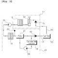
Fig. 1 is a blockdiagram showing a configuration of a fuel system for an excavator in accordance with an embodiment of the present invention. -
- 10:
- fuel supply line
- 11:
- engine
- 12:
- return line
- 13:
- fuel tank
- 14:
- hand pump
- 15:
- check valve
- 16:
- first filter
- 17:
- water separator
- 18:
- second filter
- 19:
- injector
- 20:
- injection pump
- 21:
- fuel control unit
- 22:
- check valve
- 23:
- pressure sensor
- 24:
- fuel supply pump
- Now, preferred embodiments of the present invention will be described in detail with reference to the accompanying drawings. The matters defined in the description, such as the detailed construction and elements, are nothing but specific details provided to assist those of ordinary skill in the art in a comprehensive understanding of the invention, and the present invention is not limited to the embodiments disclosed hereinafter.
- A fuel system for an excavator in accordance with an embodiment of the present invention as shown in
Fig. 1 includes: - a
fuel tank 13 that includes afuel supply line 10 along which fuel is discharged therefrom and areturn line 12 along which the remaining fuel is returned thereto after being combusted in a combustion chamber of anengine 11; - a
water separator 17 that includes ahand pump 14 for start-up of the engine, which is installed on a downstream side of thefuel tank 13 in such a manner as to be connected to thefuel supply line 10 and is configured to remove water contained in the intake fuel (referring to gas oil), a check valve which is installed on thefuel supply line 10, and afirst filter 16 which is connected to thehand pump 14 and is configured to filter foreign substances or water in the fuel; - an
injection pump 20 that is installed on a downstream side of thewater separator 17 and is configured to supply the fuel (referring to gas oil), from which the foreign substances are filtered while sequentially passing through thefirst filter 16 and asecond filter 18 connected to the first filter by thefuel supply pump 24, tocommon rail injector 19 at high pressure so as to inject the filtered fuel into the engine combustion chamber (not shown); - a fuel control unit (FCU) 21 that is connected to the
second filter 18 and theinjection pump 20 and is configured to control the amount of fuel that is supplied to theinjector 19 through the control of theinjection pump 20; and - a
check valve 22 that is installed on thereturn line 12 and is configured to allow the remaining fuel that is remained after being used on theengine 11 to remain on theinjector 19 side rather than being returned to thefuel tank 13 along thereturn line 12 in the case where the equipment is not operated by the start-off of the engine, so that the remaining fuel can be used during the start-up of the engine. - Herein, the fuel system may further include a
pressure sensor 23 that is installed in a pipe between thesecond filter 18 and thefuel control unit 21 and configured to detect the pressure of the fuel that has passed through thesecond filter 18 and to output a detection signal for application to thefuel control unit 21. - Hereinafter, a use example of the fuel system for an excavator in accordance with an embodiment of the present invention will be described in detail with reference to the accompanying drawings.
- As shown in
Fig. 1 , fuel (referring to gas oil) discharged from thefuel tank 13 installed at one side of a combustion chamber of the engine of the excavator is supplied to thewater separator 17 along thefuel supply line 10 and is filled in thewater separator 17. In other words, the fuel supplied to thewater separator 17 through thefuel supply line 10 sequentially passes through thecheck valve 15 and thefirst filter 16, which are installed on thefuel supply line 10, by the pumping operation of thehand pump 14, so that water or foreign substances contained in the fuel (gas oil) can be removed. - Then, the fuel from which water or the like is removed by the
water separator 17 is supplied to theengine 11 by the pumping operation of thefuel supply pump 24. That is, the fuel passing through thefuel supply pump 24 passes through thesecond filter 15, and then is supplied to thecommon rail injector 19 at high pressure by the pumping operation of theinjection pump 20 under the control of thefuel control unit 21. In this case, the pressure of the fuel passing through thesecond filter 15 is detected by thepressure sensor 23, which in turn outputs a detection signal for application to thefuel control unit 21. In other words, theinjection pump 20 is controlled by a control signal from thefuel control unit 21 based on the detected pressure value of the fuel so that the amount of the fuel supplied to theinjector 19 can be controlled. - Thus, the fuel is injected by a predetermined amount into the combustion chamber of the
engine 11 through the nozzle of theinjector 19 in response to a control signal from an ECU (not shown) so that the fuel is burned in the cylinder. - In this case, the fuel supplied to the
engine 11 from thefuel tank 13 is sprayed into and combusted in the combustion chamber of the engine according to an engine state mode, and the remaining fuel remained after combustion is returned to thefuel tank 13 along thereturn line 12 to thereby form a fuel supply circulation cycle. - As one example, in the case where the work is completed and the equipment is suspended in operation so as to be left to stand idle by the start off of the
engine 11, the remaining fuel remained after being combusted on the engine 11stays on theinjector 19 side of the engine by means of thecheck valve 22 installed on thereturn line 12, but is not returned to thefuel tank 13. On the contrary, conventionally, the remaining fuel remained on the engine is returned to the fuel tank along the return line. Thus, in order to start up the engine in a state in which the engine is suspended in operation for a predetermined time period, it is not until the hand pump constituting the water separator is operated that the fuel for start-up is supplied to the engine. - For this reason, in the case where the engine is started up in a state in which the engine is suspended in operation for a predetermined time period, the fuel needed to start up the
engine 11 is secured even without operating thehand pump 14 for start-up so that the start-up performance of the engine can be improved. Moreover, since the manipulation of thehand pump 14 is not required to start up theengine 11, internal leakage of oil and damage of parts such as thehand pump 14, thecheck valve 15, and the like due to a rise of pressure according to an excessive manipulation of the hand pump can be prevented. - While the present invention has been described in connection with the specific embodiments illustrated in the drawings, they are merely illustrative, and the invention is not limited to these embodiments. It is to be understood that various equivalent modifications and variations of the embodiments can be made by a person having an ordinary skill in the art without departing from the spirit and scope of the present invention. Therefore, the true technical scope of the present invention should not be defined by the above-mentioned embodiments but should be defined by the appended claims and equivalents thereof.
- As described above, according to the fuel system for an excavator in accordance with an embodiment of the present invention, in the case where the equipment is not operated by the start-off of the engine, the remaining fuel that is remained after being used on the engine remains on the common rail injector side without being returned to the fuel tank so that the start-up performance of the engine can be improved. In addition, since the manipulation of the hand pump is not required to start up the engine, internal leakage of oil and damage of parts such as the hand pump, and the like due to a rise of pressure according to an excessive manipulation of the hand pump can be prevented.
Claims (2)
- A fuel system for an excavator comprising:a fuel tankincluding a fuel supply linealong which fuel is discharged therefrom and a return line along which the remaining fuel is returned thereto after being combusted on an engine;a water separatorincluding a hand pumpinstalled on a downstream side of the fuel tankin such a manner as to be connected to the fuel supply line and configured to remove water contained in the intake fuel and, and a first filterconnected to the hand pump and configured to filter foreign substances in the fuel;an injection pumpinstalled on a downstream side of the water separator and configured to supply the fuel, from which the foreign substances are filtered while passing through the first filterand a second filterconnected to the first filter, to an injectorat high pressure so as to inject the filtered fuel into an engine combustion chamber;a fuel control unitconnected to the second filterand the injection pump and configured to control the amount of fuel that is supplied to the injectorthrough the control of the injection pump; anda check valveinstalled on the return line and configured to allow the remaining fuel that is remained after being used on the engine to remain on the injectorside rather than being returned to the fuel tankalong the return linein the case where the equipment is not operated by the start-off of the engine.
- The fuel system according to claim 1, further comprising a pressure sensor installed in a pipe between the second filterand the fuel control unit and configured to detect the pressure of the fuel that has passed through the second filterand to output a detection signal for application to the fuel control unit.
Applications Claiming Priority (1)
| Application Number | Priority Date | Filing Date | Title |
|---|---|---|---|
| PCT/KR2011/005142 WO2013008968A1 (en) | 2011-07-13 | 2011-07-13 | Fuel system for an excavator |
Publications (3)
| Publication Number | Publication Date |
|---|---|
| EP2735722A1 true EP2735722A1 (en) | 2014-05-28 |
| EP2735722A4 EP2735722A4 (en) | 2015-05-13 |
| EP2735722B1 EP2735722B1 (en) | 2017-03-01 |
Family
ID=47506238
Family Applications (1)
| Application Number | Title | Priority Date | Filing Date |
|---|---|---|---|
| EP11869344.9A Not-in-force EP2735722B1 (en) | 2011-07-13 | 2011-07-13 | Fuel system for an excavator |
Country Status (6)
| Country | Link |
|---|---|
| US (1) | US9388779B2 (en) |
| EP (1) | EP2735722B1 (en) |
| JP (1) | JP2014522942A (en) |
| KR (1) | KR101770731B1 (en) |
| CN (1) | CN103649517B (en) |
| WO (1) | WO2013008968A1 (en) |
Families Citing this family (3)
| Publication number | Priority date | Publication date | Assignee | Title |
|---|---|---|---|---|
| GB2521284B (en) | 2012-07-25 | 2017-03-08 | Volvo Constr Equip Ab | Structure for preventing heat of muffler for contruction machine from being diffused |
| DE102016222778A1 (en) * | 2016-11-18 | 2018-05-24 | Siemens Aktiengesellschaft | Process for dewatering a fuel, dewatering device and fuel supply device |
| CN107620659B (en) * | 2017-10-30 | 2023-11-24 | 潍柴动力股份有限公司 | Fuel filter anti-reverse connection oil system, fuel filter and engine |
Family Cites Families (27)
| Publication number | Priority date | Publication date | Assignee | Title |
|---|---|---|---|---|
| US4288086A (en) * | 1980-01-22 | 1981-09-08 | International Harvester Company | Fuel tank arrangement for a tractor |
| JPS59141159U (en) * | 1983-03-10 | 1984-09-20 | 日産自動車株式会社 | Diesel engine fuel water separator |
| JP3223806B2 (en) * | 1996-08-27 | 2001-10-29 | 三菱自動車工業株式会社 | Engine testing equipment |
| DE19954695A1 (en) * | 1999-11-13 | 2001-05-23 | Bosch Gmbh Robert | Fuel injection system |
| US6328883B1 (en) * | 2000-05-31 | 2001-12-11 | Parker-Hannifin Corporation | Fuel filter assembly with priming pump |
| JP2002147303A (en) * | 2000-11-14 | 2002-05-22 | Keihin Corp | Fuel supply system for outboard motor |
| JP4399697B2 (en) * | 2001-02-28 | 2010-01-20 | 株式会社デンソー | Fuel supply device and fuel filtration device |
| JP2002317721A (en) * | 2001-04-24 | 2002-10-31 | Keihin Corp | Outboard fuel injection system |
| JP3941479B2 (en) * | 2001-11-28 | 2007-07-04 | 株式会社デンソー | Fuel supply device |
| JP4340627B2 (en) * | 2002-06-19 | 2009-10-07 | ボルボ ラストバグナー アーベー | Fuel injection device for internal combustion engine |
| JP4135666B2 (en) * | 2004-03-24 | 2008-08-20 | トヨタ自動車株式会社 | Engine fuel supply control device |
| JP4211733B2 (en) * | 2004-12-08 | 2009-01-21 | 株式会社デンソー | Common rail fuel injection system |
| JP4670450B2 (en) * | 2005-04-15 | 2011-04-13 | トヨタ自動車株式会社 | Fuel supply device for internal combustion engine |
| US7527739B2 (en) * | 2005-08-15 | 2009-05-05 | Fleetguard Inc | Apparatus, system, and method for multistage water separation |
| JP4364193B2 (en) | 2005-12-15 | 2009-11-11 | 日立建機株式会社 | Construction equipment fuel supply system |
| JP2007285235A (en) * | 2006-04-18 | 2007-11-01 | Honda Motor Co Ltd | Fuel supply system for diesel engine |
| JP2008151077A (en) * | 2006-12-19 | 2008-07-03 | Toyota Motor Corp | Fuel injection device |
| JP2008180208A (en) * | 2006-12-27 | 2008-08-07 | Denso Corp | Fuel supply device |
| DE102007000855B4 (en) * | 2006-12-27 | 2020-06-10 | Denso Corporation | Fuel delivery device and storage fuel injection system having this |
| US7527043B2 (en) * | 2007-07-05 | 2009-05-05 | Caterpillar Inc. | Liquid fuel system with anti-drainback valve and engine using same |
| JP4518140B2 (en) * | 2007-12-05 | 2010-08-04 | 株式会社デンソー | Fuel supply device |
| JP5004353B2 (en) * | 2007-12-28 | 2012-08-22 | ボッシュ株式会社 | Fuel supply device for internal combustion engine and control device for fuel supply device |
| JP4888437B2 (en) * | 2008-05-07 | 2012-02-29 | 株式会社デンソー | Fuel filter replacement time determination device and fuel supply system |
| JP2009293541A (en) * | 2008-06-06 | 2009-12-17 | Bosch Corp | Accumulator fuel system for internal combustion engine |
| JP5182012B2 (en) * | 2008-10-28 | 2013-04-10 | いすゞ自動車株式会社 | Method for determining clogging life of fuel filter of internal combustion engine and internal combustion engine using the same |
| JP5176948B2 (en) * | 2008-12-26 | 2013-04-03 | 株式会社デンソー | Fuel supply device and high-pressure pump |
| JP5423334B2 (en) * | 2009-11-17 | 2014-02-19 | 株式会社デンソー | Fuel filter regeneration control device |
-
2011
- 2011-07-13 WO PCT/KR2011/005142 patent/WO2013008968A1/en not_active Ceased
- 2011-07-13 US US14/131,553 patent/US9388779B2/en not_active Expired - Fee Related
- 2011-07-13 KR KR1020147000145A patent/KR101770731B1/en not_active Expired - Fee Related
- 2011-07-13 JP JP2014520099A patent/JP2014522942A/en active Pending
- 2011-07-13 EP EP11869344.9A patent/EP2735722B1/en not_active Not-in-force
- 2011-07-13 CN CN201180072155.0A patent/CN103649517B/en not_active Expired - Fee Related
Also Published As
| Publication number | Publication date |
|---|---|
| CN103649517A (en) | 2014-03-19 |
| WO2013008968A1 (en) | 2013-01-17 |
| KR101770731B1 (en) | 2017-09-05 |
| EP2735722B1 (en) | 2017-03-01 |
| CN103649517B (en) | 2017-02-15 |
| US9388779B2 (en) | 2016-07-12 |
| JP2014522942A (en) | 2014-09-08 |
| US20140165968A1 (en) | 2014-06-19 |
| KR20140039023A (en) | 2014-03-31 |
| EP2735722A4 (en) | 2015-05-13 |
Similar Documents
| Publication | Publication Date | Title |
|---|---|---|
| RU2718654C2 (en) | Method for limitation of fuel injector leaks (versions) and engine system | |
| WO2011096358A1 (en) | Fuel switchover control device and method | |
| WO2013156161A1 (en) | Monitoring ignition fuel injection systems of dual fuel engines | |
| CN109424408A (en) | Strategy for diagnosing and mitigating reductant injector plugging in an exhaust system | |
| WO2015075545A1 (en) | Apparatus for controlling the fuel supply of an internal combustion engine | |
| CN103925129B (en) | fuel supply equipment | |
| US9388779B2 (en) | Fuel system for an excavator | |
| JP4787208B2 (en) | LIQUID GAS FUEL SUPPLY DEVICE AND METHOD FOR DRIVING HIGH PRESSURE PUMP | |
| KR102070486B1 (en) | Fuel injection control device for internal combustion engine | |
| CN107567539A (en) | Device for injecting water into an internal combustion engine and method for operating such a device | |
| JP5312049B2 (en) | Method and apparatus for purging a fuel injector in a fuel injection system used for regeneration of a particulate filter | |
| KR20200094682A (en) | Method for operating a water injection system of an internal combustion engine of a motor vehicle and control device | |
| JP2010216279A (en) | Fuel injection control device and accumulator fuel injection system using the same | |
| CN105986918A (en) | Control apparatus for direct injection engine | |
| JP2006161675A (en) | Fuel system diagnostic device for internal combustion engine | |
| JP5838712B2 (en) | Method for starting engine using dimethyl ether fuel and engine using dimethyl ether fuel | |
| JP6725759B2 (en) | Fuel supply system and fuel distribution block | |
| US8789361B2 (en) | Diesel aftertreatment regeneration system and method | |
| KR20170117127A (en) | The fuel supply system of the internal combustion engine | |
| KR102083690B1 (en) | A method for operating an internal combustion engine | |
| JP2011052664A (en) | Accumulator fuel injection system | |
| CN103711603B (en) | A kind of fuel pipe discharge air managing system | |
| KR200396713Y1 (en) | Cleaning system for fuel injectors of Diesel Engine | |
| JP6520690B2 (en) | Exhaust purification system | |
| KR100878085B1 (en) | High Pressure Pump Diagnosis Device and Diagnosis Method of Common Rail System |
Legal Events
| Date | Code | Title | Description |
|---|---|---|---|
| PUAI | Public reference made under article 153(3) epc to a published international application that has entered the european phase |
Free format text: ORIGINAL CODE: 0009012 |
|
| 17P | Request for examination filed |
Effective date: 20140108 |
|
| AK | Designated contracting states |
Kind code of ref document: A1 Designated state(s): AL AT BE BG CH CY CZ DE DK EE ES FI FR GB GR HR HU IE IS IT LI LT LU LV MC MK MT NL NO PL PT RO RS SE SI SK SM TR |
|
| DAX | Request for extension of the european patent (deleted) | ||
| RA4 | Supplementary search report drawn up and despatched (corrected) |
Effective date: 20150415 |
|
| RIC1 | Information provided on ipc code assigned before grant |
Ipc: F02M 59/44 20060101ALI20150409BHEP Ipc: F02D 33/00 20060101ALI20150409BHEP Ipc: E02F 3/04 20060101ALI20150409BHEP Ipc: F02M 37/22 20060101ALI20150409BHEP Ipc: F02M 37/00 20060101AFI20150409BHEP |
|
| GRAP | Despatch of communication of intention to grant a patent |
Free format text: ORIGINAL CODE: EPIDOSNIGR1 |
|
| INTG | Intention to grant announced |
Effective date: 20160926 |
|
| GRAS | Grant fee paid |
Free format text: ORIGINAL CODE: EPIDOSNIGR3 |
|
| GRAA | (expected) grant |
Free format text: ORIGINAL CODE: 0009210 |
|
| AK | Designated contracting states |
Kind code of ref document: B1 Designated state(s): AL AT BE BG CH CY CZ DE DK EE ES FI FR GB GR HR HU IE IS IT LI LT LU LV MC MK MT NL NO PL PT RO RS SE SI SK SM TR |
|
| REG | Reference to a national code |
Ref country code: GB Ref legal event code: FG4D |
|
| REG | Reference to a national code |
Ref country code: CH Ref legal event code: EP Ref country code: AT Ref legal event code: REF Ref document number: 871678 Country of ref document: AT Kind code of ref document: T Effective date: 20170315 |
|
| REG | Reference to a national code |
Ref country code: IE Ref legal event code: FG4D |
|
| REG | Reference to a national code |
Ref country code: DE Ref legal event code: R096 Ref document number: 602011035576 Country of ref document: DE |
|
| REG | Reference to a national code |
Ref country code: NL Ref legal event code: MP Effective date: 20170301 |
|
| REG | Reference to a national code |
Ref country code: LT Ref legal event code: MG4D |
|
| REG | Reference to a national code |
Ref country code: AT Ref legal event code: MK05 Ref document number: 871678 Country of ref document: AT Kind code of ref document: T Effective date: 20170301 |
|
| REG | Reference to a national code |
Ref country code: FR Ref legal event code: PLFP Year of fee payment: 7 |
|
| PG25 | Lapsed in a contracting state [announced via postgrant information from national office to epo] |
Ref country code: GR Free format text: LAPSE BECAUSE OF FAILURE TO SUBMIT A TRANSLATION OF THE DESCRIPTION OR TO PAY THE FEE WITHIN THE PRESCRIBED TIME-LIMIT Effective date: 20170602 Ref country code: LT Free format text: LAPSE BECAUSE OF FAILURE TO SUBMIT A TRANSLATION OF THE DESCRIPTION OR TO PAY THE FEE WITHIN THE PRESCRIBED TIME-LIMIT Effective date: 20170301 Ref country code: NO Free format text: LAPSE BECAUSE OF FAILURE TO SUBMIT A TRANSLATION OF THE DESCRIPTION OR TO PAY THE FEE WITHIN THE PRESCRIBED TIME-LIMIT Effective date: 20170601 Ref country code: HR Free format text: LAPSE BECAUSE OF FAILURE TO SUBMIT A TRANSLATION OF THE DESCRIPTION OR TO PAY THE FEE WITHIN THE PRESCRIBED TIME-LIMIT Effective date: 20170301 Ref country code: FI Free format text: LAPSE BECAUSE OF FAILURE TO SUBMIT A TRANSLATION OF THE DESCRIPTION OR TO PAY THE FEE WITHIN THE PRESCRIBED TIME-LIMIT Effective date: 20170301 |
|
| PG25 | Lapsed in a contracting state [announced via postgrant information from national office to epo] |
Ref country code: RS Free format text: LAPSE BECAUSE OF FAILURE TO SUBMIT A TRANSLATION OF THE DESCRIPTION OR TO PAY THE FEE WITHIN THE PRESCRIBED TIME-LIMIT Effective date: 20170301 Ref country code: AT Free format text: LAPSE BECAUSE OF FAILURE TO SUBMIT A TRANSLATION OF THE DESCRIPTION OR TO PAY THE FEE WITHIN THE PRESCRIBED TIME-LIMIT Effective date: 20170301 Ref country code: SE Free format text: LAPSE BECAUSE OF FAILURE TO SUBMIT A TRANSLATION OF THE DESCRIPTION OR TO PAY THE FEE WITHIN THE PRESCRIBED TIME-LIMIT Effective date: 20170301 Ref country code: LV Free format text: LAPSE BECAUSE OF FAILURE TO SUBMIT A TRANSLATION OF THE DESCRIPTION OR TO PAY THE FEE WITHIN THE PRESCRIBED TIME-LIMIT Effective date: 20170301 Ref country code: ES Free format text: LAPSE BECAUSE OF FAILURE TO SUBMIT A TRANSLATION OF THE DESCRIPTION OR TO PAY THE FEE WITHIN THE PRESCRIBED TIME-LIMIT Effective date: 20170301 Ref country code: BG Free format text: LAPSE BECAUSE OF FAILURE TO SUBMIT A TRANSLATION OF THE DESCRIPTION OR TO PAY THE FEE WITHIN THE PRESCRIBED TIME-LIMIT Effective date: 20170601 |
|
| PG25 | Lapsed in a contracting state [announced via postgrant information from national office to epo] |
Ref country code: NL Free format text: LAPSE BECAUSE OF FAILURE TO SUBMIT A TRANSLATION OF THE DESCRIPTION OR TO PAY THE FEE WITHIN THE PRESCRIBED TIME-LIMIT Effective date: 20170301 |
|
| PG25 | Lapsed in a contracting state [announced via postgrant information from national office to epo] |
Ref country code: SK Free format text: LAPSE BECAUSE OF FAILURE TO SUBMIT A TRANSLATION OF THE DESCRIPTION OR TO PAY THE FEE WITHIN THE PRESCRIBED TIME-LIMIT Effective date: 20170301 Ref country code: IT Free format text: LAPSE BECAUSE OF FAILURE TO SUBMIT A TRANSLATION OF THE DESCRIPTION OR TO PAY THE FEE WITHIN THE PRESCRIBED TIME-LIMIT Effective date: 20170301 Ref country code: RO Free format text: LAPSE BECAUSE OF FAILURE TO SUBMIT A TRANSLATION OF THE DESCRIPTION OR TO PAY THE FEE WITHIN THE PRESCRIBED TIME-LIMIT Effective date: 20170301 Ref country code: EE Free format text: LAPSE BECAUSE OF FAILURE TO SUBMIT A TRANSLATION OF THE DESCRIPTION OR TO PAY THE FEE WITHIN THE PRESCRIBED TIME-LIMIT Effective date: 20170301 Ref country code: CZ Free format text: LAPSE BECAUSE OF FAILURE TO SUBMIT A TRANSLATION OF THE DESCRIPTION OR TO PAY THE FEE WITHIN THE PRESCRIBED TIME-LIMIT Effective date: 20170301 |
|
| PGFP | Annual fee paid to national office [announced via postgrant information from national office to epo] |
Ref country code: GB Payment date: 20170728 Year of fee payment: 7 |
|
| PG25 | Lapsed in a contracting state [announced via postgrant information from national office to epo] |
Ref country code: PL Free format text: LAPSE BECAUSE OF FAILURE TO SUBMIT A TRANSLATION OF THE DESCRIPTION OR TO PAY THE FEE WITHIN THE PRESCRIBED TIME-LIMIT Effective date: 20170301 Ref country code: PT Free format text: LAPSE BECAUSE OF FAILURE TO SUBMIT A TRANSLATION OF THE DESCRIPTION OR TO PAY THE FEE WITHIN THE PRESCRIBED TIME-LIMIT Effective date: 20170703 Ref country code: IS Free format text: LAPSE BECAUSE OF FAILURE TO SUBMIT A TRANSLATION OF THE DESCRIPTION OR TO PAY THE FEE WITHIN THE PRESCRIBED TIME-LIMIT Effective date: 20170701 Ref country code: SM Free format text: LAPSE BECAUSE OF FAILURE TO SUBMIT A TRANSLATION OF THE DESCRIPTION OR TO PAY THE FEE WITHIN THE PRESCRIBED TIME-LIMIT Effective date: 20170301 |
|
| REG | Reference to a national code |
Ref country code: DE Ref legal event code: R097 Ref document number: 602011035576 Country of ref document: DE |
|
| PLBE | No opposition filed within time limit |
Free format text: ORIGINAL CODE: 0009261 |
|
| STAA | Information on the status of an ep patent application or granted ep patent |
Free format text: STATUS: NO OPPOSITION FILED WITHIN TIME LIMIT |
|
| PG25 | Lapsed in a contracting state [announced via postgrant information from national office to epo] |
Ref country code: DK Free format text: LAPSE BECAUSE OF FAILURE TO SUBMIT A TRANSLATION OF THE DESCRIPTION OR TO PAY THE FEE WITHIN THE PRESCRIBED TIME-LIMIT Effective date: 20170301 |
|
| 26N | No opposition filed |
Effective date: 20171204 |
|
| PG25 | Lapsed in a contracting state [announced via postgrant information from national office to epo] |
Ref country code: SI Free format text: LAPSE BECAUSE OF FAILURE TO SUBMIT A TRANSLATION OF THE DESCRIPTION OR TO PAY THE FEE WITHIN THE PRESCRIBED TIME-LIMIT Effective date: 20170301 |
|
| REG | Reference to a national code |
Ref country code: CH Ref legal event code: PL |
|
| REG | Reference to a national code |
Ref country code: IE Ref legal event code: MM4A |
|
| PG25 | Lapsed in a contracting state [announced via postgrant information from national office to epo] |
Ref country code: CH Free format text: LAPSE BECAUSE OF NON-PAYMENT OF DUE FEES Effective date: 20170731 Ref country code: IE Free format text: LAPSE BECAUSE OF NON-PAYMENT OF DUE FEES Effective date: 20170713 Ref country code: LI Free format text: LAPSE BECAUSE OF NON-PAYMENT OF DUE FEES Effective date: 20170731 |
|
| REG | Reference to a national code |
Ref country code: BE Ref legal event code: MM Effective date: 20170731 |
|
| PG25 | Lapsed in a contracting state [announced via postgrant information from national office to epo] |
Ref country code: LU Free format text: LAPSE BECAUSE OF NON-PAYMENT OF DUE FEES Effective date: 20170713 |
|
| REG | Reference to a national code |
Ref country code: FR Ref legal event code: PLFP Year of fee payment: 8 |
|
| PG25 | Lapsed in a contracting state [announced via postgrant information from national office to epo] |
Ref country code: BE Free format text: LAPSE BECAUSE OF NON-PAYMENT OF DUE FEES Effective date: 20170731 |
|
| PG25 | Lapsed in a contracting state [announced via postgrant information from national office to epo] |
Ref country code: MT Free format text: LAPSE BECAUSE OF NON-PAYMENT OF DUE FEES Effective date: 20170713 |
|
| GBPC | Gb: european patent ceased through non-payment of renewal fee |
Effective date: 20180713 |
|
| PG25 | Lapsed in a contracting state [announced via postgrant information from national office to epo] |
Ref country code: GB Free format text: LAPSE BECAUSE OF NON-PAYMENT OF DUE FEES Effective date: 20180713 |
|
| PG25 | Lapsed in a contracting state [announced via postgrant information from national office to epo] |
Ref country code: MC Free format text: LAPSE BECAUSE OF FAILURE TO SUBMIT A TRANSLATION OF THE DESCRIPTION OR TO PAY THE FEE WITHIN THE PRESCRIBED TIME-LIMIT Effective date: 20170301 Ref country code: HU Free format text: LAPSE BECAUSE OF FAILURE TO SUBMIT A TRANSLATION OF THE DESCRIPTION OR TO PAY THE FEE WITHIN THE PRESCRIBED TIME-LIMIT; INVALID AB INITIO Effective date: 20110713 |
|
| PG25 | Lapsed in a contracting state [announced via postgrant information from national office to epo] |
Ref country code: CY Free format text: LAPSE BECAUSE OF NON-PAYMENT OF DUE FEES Effective date: 20170301 |
|
| PG25 | Lapsed in a contracting state [announced via postgrant information from national office to epo] |
Ref country code: MK Free format text: LAPSE BECAUSE OF FAILURE TO SUBMIT A TRANSLATION OF THE DESCRIPTION OR TO PAY THE FEE WITHIN THE PRESCRIBED TIME-LIMIT Effective date: 20170301 |
|
| PG25 | Lapsed in a contracting state [announced via postgrant information from national office to epo] |
Ref country code: TR Free format text: LAPSE BECAUSE OF FAILURE TO SUBMIT A TRANSLATION OF THE DESCRIPTION OR TO PAY THE FEE WITHIN THE PRESCRIBED TIME-LIMIT Effective date: 20170301 |
|
| PG25 | Lapsed in a contracting state [announced via postgrant information from national office to epo] |
Ref country code: AL Free format text: LAPSE BECAUSE OF FAILURE TO SUBMIT A TRANSLATION OF THE DESCRIPTION OR TO PAY THE FEE WITHIN THE PRESCRIBED TIME-LIMIT Effective date: 20170301 |
|
| PGFP | Annual fee paid to national office [announced via postgrant information from national office to epo] |
Ref country code: FR Payment date: 20230725 Year of fee payment: 13 Ref country code: DE Payment date: 20230726 Year of fee payment: 13 |
|
| REG | Reference to a national code |
Ref country code: DE Ref legal event code: R119 Ref document number: 602011035576 Country of ref document: DE |
|
| PG25 | Lapsed in a contracting state [announced via postgrant information from national office to epo] |
Ref country code: DE Free format text: LAPSE BECAUSE OF NON-PAYMENT OF DUE FEES Effective date: 20250201 |
|
| PG25 | Lapsed in a contracting state [announced via postgrant information from national office to epo] |
Ref country code: FR Free format text: LAPSE BECAUSE OF NON-PAYMENT OF DUE FEES Effective date: 20240731 |