EP2735647A1 - Fiber web machine - Google Patents
Fiber web machine Download PDFInfo
- Publication number
- EP2735647A1 EP2735647A1 EP13192894.7A EP13192894A EP2735647A1 EP 2735647 A1 EP2735647 A1 EP 2735647A1 EP 13192894 A EP13192894 A EP 13192894A EP 2735647 A1 EP2735647 A1 EP 2735647A1
- Authority
- EP
- European Patent Office
- Prior art keywords
- fiber web
- web machine
- container
- section
- machine
- Prior art date
- Legal status (The legal status is an assumption and is not a legal conclusion. Google has not performed a legal analysis and makes no representation as to the accuracy of the status listed.)
- Withdrawn
Links
- 239000000835 fiber Substances 0.000 title claims abstract description 72
- 238000002360 preparation method Methods 0.000 claims description 7
- 239000002657 fibrous material Substances 0.000 claims description 4
- 238000011282 treatment Methods 0.000 claims description 3
- 238000001035 drying Methods 0.000 claims description 2
- 238000003825 pressing Methods 0.000 claims description 2
- XLYOFNOQVPJJNP-UHFFFAOYSA-N water Substances O XLYOFNOQVPJJNP-UHFFFAOYSA-N 0.000 claims description 2
- 238000010790 dilution Methods 0.000 description 1
- 239000012895 dilution Substances 0.000 description 1
- 238000002156 mixing Methods 0.000 description 1
- 238000012986 modification Methods 0.000 description 1
- 230000004048 modification Effects 0.000 description 1
Images


Classifications
-
- D—TEXTILES; PAPER
- D21—PAPER-MAKING; PRODUCTION OF CELLULOSE
- D21F—PAPER-MAKING MACHINES; METHODS OF PRODUCING PAPER THEREON
- D21F9/00—Complete machines for making continuous webs of paper
-
- B—PERFORMING OPERATIONS; TRANSPORTING
- B65—CONVEYING; PACKING; STORING; HANDLING THIN OR FILAMENTARY MATERIAL
- B65D—CONTAINERS FOR STORAGE OR TRANSPORT OF ARTICLES OR MATERIALS, e.g. BAGS, BARRELS, BOTTLES, BOXES, CANS, CARTONS, CRATES, DRUMS, JARS, TANKS, HOPPERS, FORWARDING CONTAINERS; ACCESSORIES, CLOSURES, OR FITTINGS THEREFOR; PACKAGING ELEMENTS; PACKAGES
- B65D85/00—Containers, packaging elements or packages, specially adapted for particular articles or materials
- B65D85/68—Containers, packaging elements or packages, specially adapted for particular articles or materials for machines, engines or vehicles in assembled or dismantled form
-
- B—PERFORMING OPERATIONS; TRANSPORTING
- B65—CONVEYING; PACKING; STORING; HANDLING THIN OR FILAMENTARY MATERIAL
- B65D—CONTAINERS FOR STORAGE OR TRANSPORT OF ARTICLES OR MATERIALS, e.g. BAGS, BARRELS, BOTTLES, BOXES, CANS, CARTONS, CRATES, DRUMS, JARS, TANKS, HOPPERS, FORWARDING CONTAINERS; ACCESSORIES, CLOSURES, OR FITTINGS THEREFOR; PACKAGING ELEMENTS; PACKAGES
- B65D90/00—Component parts, details or accessories for large containers
- B65D90/12—Supports
-
- D—TEXTILES; PAPER
- D21—PAPER-MAKING; PRODUCTION OF CELLULOSE
- D21G—CALENDERS; ACCESSORIES FOR PAPER-MAKING MACHINES
- D21G9/00—Other accessories for paper-making machines
Definitions
- the finishing section 140 may comprise a calender, a sizer or a coater.
- the finishing section 150 is two containers 200 wide and one container 200 long, but it may also be different sized.
- the finishing section comprises a multinip calender the containers 200 can be arranged in a vertical direction.
- the last section in this example of a fiber web machine 100 is a reeling section 160 in which the fiber web is reeled into a machine reel. Other parts of the fiber web mill than the fiber web machine 100 itself can be arranged in containers 200 as well.
- figure 1 shows an air pipe 170 and a pulper 180 arranged in containers 200.
Landscapes
- Engineering & Computer Science (AREA)
- Mechanical Engineering (AREA)
- Paper (AREA)
Abstract
Description
- The invention relates to a fiber web machine according to the preamble of claim 1.
- Fiber web machines are normally planned and constructed to be used on the same place during the whole lifetime of the paper, board or tissue machine.
- There is, however, especially in emerging markets a need for a small size standard fiber web machine, which can be erected and dismantled easily. A small size fiber web machine refers to a fiber web machine producing less than 150 000 tons per year.
- The expression fiber web machine is used in this application for a paper, a board or a tissue machine.
- The object of the invention is to achieve a modular fiber web machine which is easy to move from place to place depending on the need. The modular fiber web machine of the invention is fast to assemble and start up.
- The fiber web machine according to the invention is characterized by the features in the characterizing portion of claim 1.
- The fiber web machine according to the invention comprises a wire section, a press section, a dryer section and a reeling section. The fiber web machine is characterized in that the fiber web machine is built up of modules so that each module is supported within a container and that at least a part of said section is arranged at least partly inside the container in a built-up state of the fiber web machine.
- Different modules of the fiber web machine are packed and supported in standard size containers. The fiber web machine can thus be transported in standard size containers to the site. The fiber web machine is then assembled at the site from the different modules situated in the containers. The modules are supported within the containers i.e. the containers will form support structures for the modules in the fiber web machine. The panels on the outer surface of the container could be removed or used for some purpose when the fiber web machine is assembled on the site. The panels will be used at least in the dryer section to form part of the hood of the dryer section. The extra space needed for arranging the air circulation in the dryer section is achieved by widening the panels beyond the dimensions of the support structures of the containers.
- The containers can be positioned in the horizontal direction or the vertical direction when the fiber web machine is assembled. The containers containing the mass tanks are assembled in the vertical direction. A first mass tank is formed from four containers assembled together and a second mass tank is formed from another four containers assembled together. The first and the second mass tank are assembled in the vertical direction on top of each other. The containers forming one mass tank could e.g. be connected by a male and female connection with suitable tightening means.
- 40 feet and 20 feet standard size containers are used for accommodating the modules of the fiber web machine. The outer dimensions of a standard 40 feet container are the following: length = 12,192 m, width = 2,44 m and height = 2,59 m. The width and the height are the same for a standard 20 feet container, but the length is 6,05 m. The carrying capacity for a 40 feet container is 30 tons and the carrying capacity for a 24 feet container is 20 tons. The support structure within the container is specially tailored for the purpose of supporting a module of the fiber web machine.
- The fiber web machine according to the invention has a wire width preferably 1,6 m and web width preferably 1,5 m.
- The fiber web machine according to the invention can be installed in any existing suitable building on the site. There is no need to erect a special building for the fiber web machine.
- Some specific embodiments of the invention are described in the following in detail with reference to the accompanying figures, in which:
-
Figure 1 shows an overview of a fiber web machine according to the invention, -
Figure 2 shows an example of a container according to the invention, and -
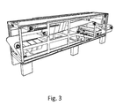
Figure 3 shows the container shown infigure 2 in an operation mode. -
Figure 1 shows an overview of a fiber web machine 100 according to the invention. The fiber web machine 100 comprises in this example first a pre-machine section comprising a stock preparation section 110 for producing fibrous material to be supplied into a headbox 121. Thefigure 1 shows an overview of the stock preparation section 110 in which for example a pulp storage tower and a reject storage tower are arranged in a vertical direction on top of each other and each storage tower is assembled from four containers 200 connected together. The stock preparation section 110 also comprises normal mechanical treatments of the stock and blending of the main stock components. The stock preparation section 110 starts with repulping or dilution of pulp and ends at the machine chest. Infigure 1 the stock preparation section 110 also covers the short circulation and the approach flow system extending from the machine chest to the headbox 121. All the different modules in the stock preparation section 110, or in any other section of the fiber web machine 100 according to the invention, are sized such that a container 200 has a capacity for a module or at least for a part of a module to fit inside to the container 200, i.e. when a module or a part of a module is transported to a mill site it fits inside a container 200 but in an assembled state the module or a part of the module can also extend outside of the container although a container 200 forms still at least a part of a supporting structure of the fiber web machine.Figure 1 shows that the headbox 121 starts the wire section 120 for spreading the fibrous material onto a wire to form the fiber web. The wire section 120 comprises one container 200 in which the wire section 120 arranged. A press section 130 follows the wire section for removing water from the fiber web by pressing it. The press section 130 is in this embodiment of the invention formed from two successive containers 200 which are assembled together in a longitudinal direction. Each container 200 forming the longitudinal press section 130 comprises also one smaller container 200 arranged crosswise as compared to the main longitudinal container 200 and such that the smaller container 200 goes through the main container 200. For example rolls can be arranged in these smaller crosswise arranged containers 200. A dryer section 140 follows the press section 130 for drying said fiber web. The dryer section 140 is arranged from eight containers 200 such that the section 140 is two containers 200 wide and four containers 200 long. Because of the character of the dryer section 140 the containers 200 have outside panels in place. A finishing section 150 for applying finishing treatment to the fiber web follows the dryer section 140. The finishing section 140 may comprise a calender, a sizer or a coater. In this embodiment the finishing section 150 is two containers 200 wide and one container 200 long, but it may also be different sized. For example if the finishing section comprises a multinip calender the containers 200 can be arranged in a vertical direction. The last section in this example of a fiber web machine 100 is a reeling section 160 in which the fiber web is reeled into a machine reel. Other parts of the fiber web mill than the fiber web machine 100 itself can be arranged in containers 200 as well. For examplefigure 1 shows an air pipe 170 and a pulper 180 arranged in containers 200. -
Figure 2 shows an example of a container 200 according to the invention. The container 200 is a standard size container having a rectangular frame 201 and side walls 202, roof panels 203, floor panels 204 and end walls 205 arranged to the frame 201. As shown infigure 2 the container 200 is a closed container, i.e. it is closed on all sides. Preferably all the sides can be removed separately depending on the use of it. When the fiber web machine 100 is assembled the containers 200 are preferably equipped with foundation beams 210 arranged in the corners of the container 200 and preferably somewhere in between two opposing corners. -
Figure 3 shows the container 200 shown infigure 2 in an operation mode. In this example in an operation mode the side walls 203, the roof panels 204, the floor panels 204 and the end walls 205 (all shown infig. 2 ) are removed showing rolls 300 and other fiber web machine parts inside the container 200. In an operation mode some rolls 301 are arranged to extend outside of the container 200 area but are movable inside to the container 200 again when the fiber web machine 100 is disassembled. The frame 201 of the container 200 forms a supporting structure to the part of the fiber web machine 100 which is arranged at least partly inside the container 200. The containers 200 can be combined such that the frames 201 of the containers 200 form a supporting structure for the whole fiber web machine 100. - The examples of the embodiments of the present invention presented above are not intended to limit the scope of the invention only to these embodiments. Several modifications can be made to the invention within the scope of the claims.
- The fiber web machine according to the invention comprises a wire section, a press section, a dryer section and a reeling section. The fiber web machine is characterized in that the fiber web machine is built up of modules so that each module is supported within a standard size container.
Claims (8)
- A fiber web machine (100) for producing fiber web, the fiber web machine (100) comprises at least
a wire section (120) comprising a headbox (121) for spreading fibrous material onto a wire to form the fiber web,
a press section (130) for removing water from the fiber web by pressing it,
a dryer section (140) for drying said fiber web, and
a reeling section (160) for reeling said fiber web into a machine reel, said sections (120, 130, 140, 150, 160) form at least a part of the fiber web machine (100),
characterized
in that the fiber web machine (100) is built up of modules such that each module is supported within a container (200) and that at least a part of said section (120, 130, 140, 150, 160) is arranged at least partly inside the container (200) in a built-up state of the fiber web machine (100). - The fiber web machine (100) according to claim 1, characterized in that the container (200) comprises a frame (201) which forms a supporting structure for said at least a part of said section (110, 120, 130, 140, 150, 160).
- The fiber web machine (100) according to claim 1 or 2, characterized in that the container (200) is a standard size container.
- The fiber web machine (100) according to claim 1 or 2, characterized in that the fiber web machine (100) further comprises a pre-machine section comprising at least a stock preparation section (110) for producing fibrous material to be supplied into the headbox (121), and that at least a part of said section (110) is arranged at least partly inside the container (200) in a built-up state of the fiber web machine (100).
- The fiber web machine (100) according to any previous claim, characterized in that the fiber web machine (100) further comprises a finishing section (150) for applying finishing treatment to said fiber web.
- The fiber web machine (100) according to any previous claim, characterized in that the fiber web machine (100) in a built-up state is arranged such that the containers (200) are arranged next to each other in a horizontal direction and/or in a vertical direction.
- The fiber web machine (100) according to any previous claim, characterized in that the container (200) comprises mechanical connection means for functionally releasable connecting the containers together.
- A container (200) for freight or shipping purpose comprising a frame (201), characterized in that a part of a fiber web machine (100) is arranged inside said container (200) such that the container (200) forms a supporting structure for said part of the fiber web machine (100).
Applications Claiming Priority (1)
| Application Number | Priority Date | Filing Date | Title |
|---|---|---|---|
| FI20126230A FI124143B (en) | 2012-11-23 | 2012-11-23 | FIBER BANA MACHINE AND CONTAINER |
Publications (1)
| Publication Number | Publication Date |
|---|---|
| EP2735647A1 true EP2735647A1 (en) | 2014-05-28 |
Family
ID=49596103
Family Applications (1)
| Application Number | Title | Priority Date | Filing Date |
|---|---|---|---|
| EP13192894.7A Withdrawn EP2735647A1 (en) | 2012-11-23 | 2013-11-14 | Fiber web machine |
Country Status (3)
| Country | Link |
|---|---|
| EP (1) | EP2735647A1 (en) |
| CN (1) | CN103835177B (en) |
| FI (1) | FI124143B (en) |
Cited By (1)
| Publication number | Priority date | Publication date | Assignee | Title |
|---|---|---|---|---|
| EP3599308A1 (en) * | 2018-07-26 | 2020-01-29 | Andritz Küsters GmbH | Device for producing nonwoven webs and method for assembling such a device |
Citations (3)
| Publication number | Priority date | Publication date | Assignee | Title |
|---|---|---|---|---|
| EP1669493A1 (en) * | 2004-12-09 | 2006-06-14 | Voith Paper Patent GmbH | Modular machine for producing or/and treating or/and handling a running web of material, in particular of paper or cardboard |
| WO2008018819A1 (en) * | 2006-08-10 | 2008-02-14 | Metso Paper Karlstad Ab | Unit in a forming section of a papermaking machine |
| WO2010106229A1 (en) * | 2009-03-18 | 2010-09-23 | Oy Langh Ship Ab | Transport frame |
Family Cites Families (1)
| Publication number | Priority date | Publication date | Assignee | Title |
|---|---|---|---|---|
| DD71131A1 (en) * | 1968-08-19 | 1970-02-05 | Device for attaching containers to vehicles |
-
2012
- 2012-11-23 FI FI20126230A patent/FI124143B/en not_active IP Right Cessation
-
2013
- 2013-11-14 EP EP13192894.7A patent/EP2735647A1/en not_active Withdrawn
- 2013-11-25 CN CN201310604003.1A patent/CN103835177B/en not_active Expired - Fee Related
Patent Citations (3)
| Publication number | Priority date | Publication date | Assignee | Title |
|---|---|---|---|---|
| EP1669493A1 (en) * | 2004-12-09 | 2006-06-14 | Voith Paper Patent GmbH | Modular machine for producing or/and treating or/and handling a running web of material, in particular of paper or cardboard |
| WO2008018819A1 (en) * | 2006-08-10 | 2008-02-14 | Metso Paper Karlstad Ab | Unit in a forming section of a papermaking machine |
| WO2010106229A1 (en) * | 2009-03-18 | 2010-09-23 | Oy Langh Ship Ab | Transport frame |
Cited By (4)
| Publication number | Priority date | Publication date | Assignee | Title |
|---|---|---|---|---|
| EP3599308A1 (en) * | 2018-07-26 | 2020-01-29 | Andritz Küsters GmbH | Device for producing nonwoven webs and method for assembling such a device |
| DE102018118095A1 (en) * | 2018-07-26 | 2020-01-30 | Andritz Küsters Gmbh | Device for producing nonwoven webs and method for assembling such a device |
| US11421361B2 (en) | 2018-07-26 | 2022-08-23 | Andritz Kuesters Gmbh | Device for the production of nonwoven fabric webs and method for installing such a device |
| US11655574B2 (en) | 2018-07-26 | 2023-05-23 | Andritz Kuesters Gmbh | Device for the production of nonwoven fabric webs and method for installing such a device |
Also Published As
| Publication number | Publication date |
|---|---|
| FI20126230A7 (en) | 2014-03-31 |
| FI124143B (en) | 2014-03-31 |
| CN103835177B (en) | 2017-07-04 |
| CN103835177A (en) | 2014-06-04 |
Similar Documents
| Publication | Publication Date | Title |
|---|---|---|
| ES2629203T5 (en) | Method of producing a corrugated cardboard for packaging from pulp comprising NSSC pulp | |
| EP2735647A1 (en) | Fiber web machine | |
| SK289314B6 (en) | Pallet outer packaging paper, packing method of pallets using its and method for producing its | |
| CN106414844B (en) | Equipment for manufacturing fiber webs | |
| US7935224B2 (en) | Unit in a forming section of a papermaking machine | |
| CN110578265B (en) | Grooved couch roll and device comprising said couch roll | |
| US5590476A (en) | Multi-story dryer section in a paper machine | |
| US5557856A (en) | Arrangement for the space underneath a dryer section of a paper machine | |
| WO2002101143A1 (en) | A method and a device for removing broke in a plant for drying of a web-formed material | |
| US7749358B2 (en) | Installation module for a paper or board machine | |
| DE69803523T2 (en) | TRAIN FINISHING PART IN A PAPER MACHINE | |
| CN204530312U (en) | Drying racks, paper machine dryers and paper machines | |
| CN217078205U (en) | A broke processing structure and paper machine for paper machine | |
| US5051151A (en) | Side extraction pulper with screw type rotor | |
| CN213020660U (en) | Paper flat paper corner protector drying equipment | |
| EP4675039A1 (en) | Method for producing containerboard | |
| US11655574B2 (en) | Device for the production of nonwoven fabric webs and method for installing such a device | |
| SE2230351A1 (en) | Pulp mill | |
| SE2230352A1 (en) | Pulp mill | |
| CN205035699U (en) | Pair paper machine | |
| CN107537231A (en) | A kind of paper machine dust arrester | |
| US20130233502A1 (en) | Sheet forming unit for producing a material web and method for operating the sheet forming unit | |
| AT17642U1 (en) | HEAT RECOVERY PLANT FOR A SURFACE SIZE MANUFACTURING PROCESS FOR A FIBER WEB | |
| EP2199460A1 (en) | Modular frame for a press section | |
| WO1995013425A1 (en) | Sheet material manufactured piecewise and based on cellulose pulp fibres, and a method and an apparatus for manufacturing sheet material |
Legal Events
| Date | Code | Title | Description |
|---|---|---|---|
| PUAI | Public reference made under article 153(3) epc to a published international application that has entered the european phase |
Free format text: ORIGINAL CODE: 0009012 |
|
| 17P | Request for examination filed |
Effective date: 20131114 |
|
| AK | Designated contracting states |
Kind code of ref document: A1 Designated state(s): AL AT BE BG CH CY CZ DE DK EE ES FI FR GB GR HR HU IE IS IT LI LT LU LV MC MK MT NL NO PL PT RO RS SE SI SK SM TR |
|
| AX | Request for extension of the european patent |
Extension state: BA ME |
|
| R17P | Request for examination filed (corrected) |
Effective date: 20141111 |
|
| RBV | Designated contracting states (corrected) |
Designated state(s): AL AT BE BG CH CY CZ DE DK EE ES FI FR GB GR HR HU IE IS IT LI LT LU LV MC MK MT NL NO PL PT RO RS SE SI SK SM TR |
|
| STAA | Information on the status of an ep patent application or granted ep patent |
Free format text: STATUS: THE APPLICATION HAS BEEN WITHDRAWN |
|
| 18W | Application withdrawn |
Effective date: 20191211 |