EP2735458A1 - Method of determining the longitudinal pitch of tread band blocks - Google Patents
Method of determining the longitudinal pitch of tread band blocks Download PDFInfo
- Publication number
- EP2735458A1 EP2735458A1 EP13194168.4A EP13194168A EP2735458A1 EP 2735458 A1 EP2735458 A1 EP 2735458A1 EP 13194168 A EP13194168 A EP 13194168A EP 2735458 A1 EP2735458 A1 EP 2735458A1
- Authority
- EP
- European Patent Office
- Prior art keywords
- blocks
- longitudinal pitch
- longitudinal
- pitch
- speed
- Prior art date
- Legal status (The legal status is an assumption and is not a legal conclusion. Google has not performed a legal analysis and makes no representation as to the accuracy of the status listed.)
- Granted
Links
Images

Classifications
-
- B—PERFORMING OPERATIONS; TRANSPORTING
- B60—VEHICLES IN GENERAL
- B60C—VEHICLE TYRES; TYRE INFLATION; TYRE CHANGING; CONNECTING VALVES TO INFLATABLE ELASTIC BODIES IN GENERAL; DEVICES OR ARRANGEMENTS RELATED TO TYRES
- B60C11/00—Tyre tread bands; Tread patterns; Anti-skid inserts
- B60C11/03—Tread patterns
- B60C11/0318—Tread patterns irregular patterns with particular pitch sequence
-
- B—PERFORMING OPERATIONS; TRANSPORTING
- B60—VEHICLES IN GENERAL
- B60C—VEHICLE TYRES; TYRE INFLATION; TYRE CHANGING; CONNECTING VALVES TO INFLATABLE ELASTIC BODIES IN GENERAL; DEVICES OR ARRANGEMENTS RELATED TO TYRES
- B60C99/00—Subject matter not provided for in other groups of this subclass
- B60C99/006—Computer aided tyre design or simulation
Definitions
- the present invention relates to a method of determining the longitudinal pitch of tread band blocks.
- Patent Application W02012164505 describes a method of determining a best longitudinal pitch of tread band blocks, by which to minimize, at a given tyre travelling speed, the noise produced by resonance generated inside the longitudinal grooves. This method, however, fails to provide for a significant reduction in the noise produced by the road surface impact/release sequence of the front and rear edges of the tread band blocks.
- EP2335949 and EP2335950 describe methods of determining the longitudinal block pitch of a tread band, with a raised pattern comprising a number of longitudinal and transverse grooves, on the basis of a reference speed, resonance frequency, and the tyre circumference.
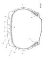
- Number 1 in Figure 1 indicates as a whole a tyre comprising a toroidal body ply 2, which has two annular beads 3 and supports a tread band 4 made of cured-rubber-based material and forming the crown of tyre 1.
- a tread belt 5, comprising two tread plies 6, is interposed between body ply 2 and tread band 4.
- Each tread ply 6 comprises a strip of rubber, in which are embedded a number of cords (not shown) arranged side by side with a given pitch and inclined at a given angle with the equatorial plane of tyre 1.
- Body ply 2 also supports two sidewalls 7 between tread band 4 and beads 3.
- Tread band 4 has a rolling surface 8, which externally bounds tread band 4 (i.e. is located radially outwards) and, in use, rests on the road surface.
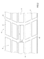
- rolling surface 8 of tread band 4 has a raised pattern comprising a number of longitudinal or circumferential grooves 9 (i.e. extending crosswise to the axis of rotation, and along the circumference, of tyre 1), and a number of transverse grooves 10 (i.e. parallel to the axis of rotation of tyre 1 and perpendicular to longitudinal grooves 9).
- Longitudinal grooves 9 and transverse grooves 10 form five longitudinal rows of blocks 11 projecting radially upwards from tread band 4.
- Each block 11 is roughly parallelepiped-shaped with a rectangular or trapezoidal cross section, and is bounded laterally by respective grooves 9 and 10.
- Blocks 11 in each row are arranged with a longitudinal pitch P equal to the sum of the longitudinal dimension of each block 11, and the longitudinal dimension L 1 of an adjacent transverse groove 10.
- Figure 3a-3c sequence shows a tyre 1 with a tread band 4 comprising a block 11 and a block 11*, each bounded at the front and rear, in the rolling direction, by two transverse grooves 10, and laterally by two longitudinal groves 9.
- the road surface impact sequence of blocks 11 and 11* show two different noise sources that contribute to generating pass-by noise (i.e. the overall external noise of a vehicle influenced by the overall external noise of each tyre 1).
- noise sources produced by the road surface impact sequence of blocks 11, 11* are the following :
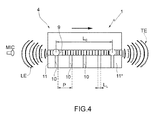
- LE noise commences the instant the front edge 12 of block 11 impacts the road surface, and the stress caused by front edge 12 of block 11 impacting the road surface is transmitted inside longitudinal grooves 9 bounding block 11; whereas TE noise commences the instant the rear edge 13 of block 11* releases the road surface, and the stress caused by rear edge 13 of block 11* releasing the road surface is transmitted inside longitudinal grooves 9 bounding block 11*.
- the two LE and TE noises may be offset in time, i.e. may commence at different times.
- the two LE and TE noises may be simultaneous, i.e. the front edge 12 of block 11 impacts the road surface at the same instant rear edge 13 of block 11* releases the road surface.
- the two LE and TE noises therefore overlap in time; which overlap may produce constructive interference, i.e. the intensities of the two LE and TE noises are added to each other, or destructive interference, i.e. the intensities of the two LE and TE noises are subtracted from each other.
- Equation [5] and assigning constant k the lowest (i.e. zero) value, to obtain an interference index I value of 0.5, give equation [9] by which to determine the best longitudinal pitch P b of block 11, 11* to minimize the contribution to pass-by noise : P b 2 ⁇ m ⁇ L 0 ⁇ V c - ⁇ ⁇ P
- Equation [9] above may therefore be used to determine the best longitudinal pitch P b of blocks 11, 11* of tyre 1 to minimize the contribution to pass-by noise at (i.e. when tyre 1 is travelling at) a target linear speed V.
- tyre 1 may be produced in two ways : with a constant longitudinal pitch (i.e. blocks 11, 11* all have the same longitudinal pitch P equal to the best longitudinal pitch P b ), or with a varying longitudinal pitch (i.e. blocks 11, 11* have different longitudinal pitches P concentrated about the best longitudinal pitch P b ).
- a constant longitudinal pitch of blocks 11, 11* (i.e. blocks 11, 11* all have the same longitudinal pitch P equal to the best longitudinal pitch P b ) has the advantage of a very small (minimum possible) contribution to pass-by noise at target speed V, but the disadvantage of the contribution to pass-by noise increasingly significantly at other than target speed V.
- a constant longitudinal pitch of blocks 11, 11* is normally used on TBR (Truck and Bus Radial) tyres mounted on vehicles that travel for long periods at the same cruising speed (typically long-distance trucks and buses using mainly motorways and therefore mostly travelling at the maximum motorway speed limit).
- tyre 1 may be designed to minimize the contribution to pass-by noise at a target speed V equal to the motorway speed limit of the relative vehicle (granted, tyre 1 will be proportionally noisier at low speeds, but overall noise at low speed is still very low.
- a varying longitudinal pitch (i.e. blocks 11, 11* have different longitudinal pitches P concentrated about the best longitudinal pitch P b ) obviously has the disadvantage of not altogether minimizing pass-by noise at target speed V, but has the advantage of also reducing the contribution to pass-by noise at other than target speed V.
- tyre 1 with a constant longitudinal pitch tyre 1 with a varying longitudinal pitch waives part of the reduction in pass-by noise at target speed V in favour of also reducing pass-by noise at other than target speed V.
- a variable longitudinal pitch of blocks 11, 11* is normally used on car tyres, in that cars are normally driven over a very wide speed range (at least up to 130 km/h) and, above all, at widely varying speeds, which therefore makes it difficult to determine one single target speed V to favour over the others (unlike long-distance motorway trucks and tour buses).
- blocks 11, 11* have different longitudinal pitches P concentrated about the best longitudinal pitch P b , i.e. within the longitudinal pitches P as a whole, the best longitudinal pitch P b predominates.
- longitudinal pitches P as a whole may form a Gaussian curve centred about the best longitudinal pitch P b , or, in the case of a very long best longitudinal pitch P b , may form an asymmetric Gaussian curve largely favouring longitudinal pitches P smaller than best longitudinal pitch P b (which nevertheless still remains predominant).
- One particular asymmetric Gaussian curve is represented by a half Gaussian curve with the upper (maximum) limit at best longitudinal pitch P b (i.e.
- best longitudinal pitch P b is the predominant and maximum value within longitudinal pitches P as a whole). In other words, because a very long longitudinal pitch P of blocks 11 may pose other than noise (e.g. water-purging) problems, longitudinal pitch P of blocks 11 is preferably kept within and no longer than best longitudinal pitch P b .
- best longitudinal pitch P b constitutes at least 40-60% of longitudinal pitches P of tyre 1 (i.e. 40-60% of longitudinal pitches P equal best longitudinal pitch P b , and the other 60-40% differ from best longitudinal pitch P b ).
- a minimum longitudinal pitch P min and maximum longitudinal pitch P max defining the range of longitudinal pitches P is determined on the basis of a minimum speed V min and maximum speed V max defining a target speed range (obviously containing target speed V) within which to reduce the contribution to pass-by noise.
- minimum longitudinal pitch P min and maximum longitudinal pitch P max are determined using equations [10] and [11] below :
- P b 2 ⁇ m ⁇ L 0 ⁇ V c - ⁇ ⁇ P
- P min 2 ⁇ m ⁇ L 0 ⁇ V min c - ⁇ ⁇ P
- P max 2 ⁇ m ⁇ L 0 ⁇ V max c - ⁇ ⁇ P
- maximum speed V max may equal 90 km/h, and minimum speed V min 70km/h.
- minimum speed V min to maximum speed V max range must not be too wide, otherwise the longitudinal pitch P range would be wide enough to also include considerable positive LE and TE noise interference.
- equations [10] and [11] to determine minimum longitudinal pitch P min and maximum longitudinal pitch P max ensures the absence of positive LE and TE noise interference, provided the minimum speed V min to maximum speed V max range is not too wide; consequently, the minimum longitudinal pitch P min to maximum longitudinal pitch P max range is smaller.
- equations [10] and [11] to determine minimum longitudinal pitch P min and maximum longitudinal pitch P max a small amount of positive LE and TE noise interference may be allowed using a wider minimum speed V min to maximum speed V max range; consequently, the minimum longitudinal pitch P min to maximum longitudinal pitch P max range is larger.
- the above method of determining the longitudinal pitch P of blocks 11, 11* substantially considers (i.e. minimizes) the noise generated by the road surface impact/release sequence of front and rear edges 12, 13 of blocks 11, 11*.
- the above method of determining the longitudinal pitch P of blocks 11, 11* provides for minimizing the noise generated by the road surface impact/release sequence of front and rear edges 12, 13 of blocks 11, 11* at a given travelling speed V of tyre 1.
- the above method of determining the longitudinal pitch P of blocks 11, 11* may be used together with the method of determining the longitudinal pitch P of blocks 11, 11* described in Italian Patent Application T02011A000471 and included herein by way of reference.
- the method of determining the longitudinal pitch P of blocks 11, 11* described in Patent Application T02011A000471 (and using equation [12]) substantially considers (i.e. minimizes) the noise produced by resonance generated inside longitudinal grooves 9.
- the method of determining the longitudinal pitch P of blocks 11, 11* described in Patent Application T02011A000471 (and using equation [12]) provides for minimizing the noise produced by resonance generated inside longitudinal grooves 9 at a given travelling V speed of tyre 1.
- best longitudinal pitch P b using equation [9] is determined, best longitudinal pitch P b ' using equation [12] can also be determined to check whether the equation [9] and [12] longitudinal pitches P b and P b ' match.
- a check can be made to determine a match (or substantial match) between best longitudinal pitch P b of blocks 11, 11*, which substantially minimizes the noise produced by the road surface impact/release sequence of front and rear edges 12 and 13 of blocks 11, 11*, and best longitudinal pitch P b ', which minimizes the noise produced by resonance generated inside longitudinal grooves 9.
- best longitudinal pitch P b and best longitudinal pitch P b ' are the best (most favourable) outcome that can occur, by providing one target longitudinal pitch P b * that satisfies both equations [9] and [12] at the same time.
- the method described of determining the longitudinal pitch P of blocks 11 of tread band 4 has numerous advantages, by enabling the longitudinal pitch P of blocks 11, 11* to be sized in such a manner as to significantly reduce the contribution to pass-by noise at (or, rather, around) a target speed V. What is more, sizing the longitudinal pitch P of blocks 11, 11* as in the method described has no negative side effects whatsoever.
Landscapes
- Engineering & Computer Science (AREA)
- Mechanical Engineering (AREA)
- Computer Hardware Design (AREA)
- General Engineering & Computer Science (AREA)
- Tires In General (AREA)
- Tyre Moulding (AREA)
Abstract
Description
- The present invention relates to a method of determining the longitudinal pitch of tread band blocks.
- Future tyre standards are expected to impose a maximum limit on the rolling noise produced by tyres. Which means technical solutions designed to reduce such noise are now a vital issue.
- Patent Application
W02012164505 describes a method of determining a best longitudinal pitch of tread band blocks, by which to minimize, at a given tyre travelling speed, the noise produced by resonance generated inside the longitudinal grooves. This method, however, fails to provide for a significant reduction in the noise produced by the road surface impact/release sequence of the front and rear edges of the tread band blocks. -
- It is an object of the present invention to provide a method of determining the longitudinal pitch of tread band blocks, which is cheap and easy to implement and, at the same time, provides for reducing pass-by noise by reducing the noise produced by the road surface impact/release sequence of the front and rear edges of the tread band blocks.
- According to the present invention, there is provided a method of determining the longitudinal pitch of tread band blocks, as claimed in the accompanying Claims.
- A non-limiting embodiment of the present invention will be described by way of example with reference to the attached drawings, in which :
-
Figure 1 shows a schematic cross section of part of a tyre; -
Figure 2 shows a schematic of part of theFigure 1 tyre tread band; -
Figure 3 shows schematics of a tyre road surface impact sequence; -
Figure 4 shows a schematic of a tyre footprint. - Number 1 in
Figure 1 indicates as a whole a tyre comprising atoroidal body ply 2, which has twoannular beads 3 and supports atread band 4 made of cured-rubber-based material and forming the crown of tyre 1. Atread belt 5, comprising twotread plies 6, is interposed betweenbody ply 2 andtread band 4. Eachtread ply 6 comprises a strip of rubber, in which are embedded a number of cords (not shown) arranged side by side with a given pitch and inclined at a given angle with the equatorial plane of tyre 1. -
Body ply 2 also supports two sidewalls 7 betweentread band 4 andbeads 3. Treadband 4 has arolling surface 8, which externally bounds tread band 4 (i.e. is located radially outwards) and, in use, rests on the road surface. - As shown in
Figure 2 ,rolling surface 8 oftread band 4 has a raised pattern comprising a number of longitudinal or circumferential grooves 9 (i.e. extending crosswise to the axis of rotation, and along the circumference, of tyre 1), and a number of transverse grooves 10 (i.e. parallel to the axis of rotation of tyre 1 and perpendicular to longitudinal grooves 9).Longitudinal grooves 9 andtransverse grooves 10 form five longitudinal rows ofblocks 11 projecting radially upwards fromtread band 4. Eachblock 11 is roughly parallelepiped-shaped with a rectangular or trapezoidal cross section, and is bounded laterally byrespective grooves Blocks 11 in each row are arranged with a longitudinal pitch P equal to the sum of the longitudinal dimension of eachblock 11, and the longitudinal dimension L1 of an adjacenttransverse groove 10. - For the sake of simplicity, the
Figure 3a-3c sequence shows a tyre 1 with atread band 4 comprising ablock 11 and ablock 11*, each bounded at the front and rear, in the rolling direction, by twotransverse grooves 10, and laterally by twolongitudinal groves 9. - The road surface impact sequence of
blocks - More specifically, the noise sources produced by the road surface impact sequence of
blocks - 1. fluctuations in pressure produced by the front (or leading)
edge 12 ofblock 11 impacting the road surface, and which generate LE noise; - 2. fluctuations in pressure produced by the rear (or trailing)
edge 13 ofblock 11* releasing the road surface, and which generate TE noise. - It is important to note that the fluctuations in pressure causing LE noise also propagate inside
longitudinal grooves 9bounding block 11; and, likewise, the fluctuations in pressure causing TE noise also propagate insidelongitudinal grooves 9 boundingblock 11*. - LE noise commences the instant the
front edge 12 ofblock 11 impacts the road surface, and the stress caused byfront edge 12 ofblock 11 impacting the road surface is transmitted insidelongitudinal grooves 9 boundingblock 11; whereas TE noise commences the instant therear edge 13 ofblock 11* releases the road surface, and the stress caused byrear edge 13 ofblock 11* releasing the road surface is transmitted insidelongitudinal grooves 9 boundingblock 11*. - In a preferred variation, the two LE and TE noises may be offset in time, i.e. may commence at different times. Alternatively, the two LE and TE noises may be simultaneous, i.e. the
front edge 12 ofblock 11 impacts the road surface at the same instantrear edge 13 ofblock 11* releases the road surface. - The two LE and TE noises therefore overlap in time; which overlap may produce constructive interference, i.e. the intensities of the two LE and TE noises are added to each other, or destructive interference, i.e. the intensities of the two LE and TE noises are subtracted from each other.
- Equation [1] below gives the emission frequency f of the road surface impact/release sequence of
blocks 
- f
- emission frequency of the road surface impact/release sequence of
blocks - m
- whole number greater than zero (i.e. 1, 2, 3, 4, ......), which represents the sequence harmonic order in which the interference is applied;
- P
- longitudinal pitch of
block block transverse groove 10; - V
- speed (linear) of tyre 1.
- Assuming the longitudinal pitch P of
block blocks - In other words, at certain linear speeds V of tyre 1, interference between the two LE and TE noises is totally constructive, so the contribution to pass-by noise (equal to the sum of the LE and TE noises) is maximum (i.e. has relative maximums); whereas, at other linear speeds V of tyre 1, interference between the two LE and TE noises is totally destructive, so the contribution to pass-by noise (equal to the sum of the LE and TE noises) is minimum (i.e. has relative minimums).
- Equation [2] below, obtained experimentally, provides for determining when (i.e. at which speeds V of tyre 1) the relative minimums of the contribution to pass-by noise occur (i.e. when interference between the two LE and TE noises is totally destructive) :

- f
- emission frequency of the road surface impact/release sequence of
blocks - k
- whole number of zero or over (i.e. 0, 1, 2, 3, 4, ......) ;
- V
- linear speed of tyre 1;
- c
- speed of sound;
- L0
- length of contact area of
blocks Figure 4 , equals the distance between the two sources of LE and TE noise; - P
- longitudinal pitch of
block block transverse groove 10; - ΔP
- impact/release sequence geometric offset index of
blocks - The impact/release sequence geometric offset index of
blocks 
- ΔP
- impact/release sequence geometric offset index of
blocks - L1
- longitudinal dimension of
transverse groove 10 boundingblock - P
- longitudinal pitch of
block block transverse groove 10; - r
- fraction coefficient.
- Fraction coefficient r can be calculated using equation [4] below :
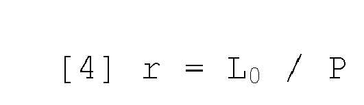
- L0
- length of contact area of
blocks Figure 4 , equals the distance between the two sources of LE and TE noise; - P
- longitudinal pitch of
block - Inserting equation [1], expressing the emission frequency f of the road surface impact/release sequence of
blocks 
- Assuming a constant m value of 1 in the impact/release sequence of
blocks 
- V
- linear speed of tyre 1;
- c
- speed of sound;
- L0
- length of contact area of
blocks Figure 4 , equals the distance between the two sources of LE and TE noise; - P
- longitudinal pitch of
block block transverse groove 10; - ΔP
- impact/release sequence geometric offset index of
blocks - k
- whole number greater than zero (i.e. 1, 2, 3, 4, ......).
- The interference index I may now be defined as follows :

- V
- linear speed of tyre 1;
- c
- speed of sound;
- L0
- length of contact area of
blocks Figure 4 , equals the distance between the two sources of LE and TE noise; - P
- longitudinal pitch of
block block transverse groove 10; - ΔP
- impact/release sequence geometric offset index of
blocks - I
- interference index.
- Simply substituting equation [7] in equation [6] gives :

- Tests show it preferable to assign constant k the lowest (i.e. zero) value, to obtain an interference index I value of 0.5 in equation [8].
- Equation [5] and assigning constant k the lowest (i.e. zero) value, to obtain an interference index I value of 0.5, give equation [9] by which to determine the best longitudinal pitch Pb of
block 
- Pb
- best longitudinal pitch of
block 11; - m
- whole number greater than zero (i.e. 1, 2, 3, 4, .........);
- L0
- length of contact area of
blocks Figure 4 , equals the distance between the two sources of LE and TE noise; - V
- linear speed of tyre 1;
- c
- speed of sound;
- ΔP
- impact/release sequence geometric offset index of
blocks - Equation [9] above may therefore be used to determine the best longitudinal pitch Pb of
blocks - In other words, to minimize the contribution of the tyre to pass-by noise when tyre 1 is travelling at a target linear speed V, this can be done using the above equation [9] to determine the best longitudinal pitch Pb of
blocks - Once the best longitudinal pitch Pb of
blocks - A constant longitudinal pitch of
blocks blocks - A varying longitudinal pitch (i.e. blocks 11, 11* have different longitudinal pitches P concentrated about the best longitudinal pitch Pb) obviously has the disadvantage of not altogether minimizing pass-by noise at target speed V, but has the advantage of also reducing the contribution to pass-by noise at other than target speed V. In other words, compared with the same tyre 1 with a constant longitudinal pitch, tyre 1 with a varying longitudinal pitch waives part of the reduction in pass-by noise at target speed V in favour of also reducing pass-by noise at other than target speed V. A variable longitudinal pitch of
blocks - In the case of a varying longitudinal pitch, blocks 11, 11* have different longitudinal pitches P concentrated about the best longitudinal pitch Pb, i.e. within the longitudinal pitches P as a whole, the best longitudinal pitch Pb predominates. For example, longitudinal pitches P as a whole may form a Gaussian curve centred about the best longitudinal pitch Pb, or, in the case of a very long best longitudinal pitch Pb, may form an asymmetric Gaussian curve largely favouring longitudinal pitches P smaller than best longitudinal pitch Pb (which nevertheless still remains predominant). One particular asymmetric Gaussian curve is represented by a half Gaussian curve with the upper (maximum) limit at best longitudinal pitch Pb (i.e. best longitudinal pitch Pb is the predominant and maximum value within longitudinal pitches P as a whole). In other words, because a very long longitudinal pitch P of
blocks 11 may pose other than noise (e.g. water-purging) problems, longitudinal pitch P ofblocks 11 is preferably kept within and no longer than best longitudinal pitch Pb. In a preferred varying-pitch embodiment, best longitudinal pitch Pb constitutes at least 40-60% of longitudinal pitches P of tyre 1 (i.e. 40-60% of longitudinal pitches P equal best longitudinal pitch Pb, and the other 60-40% differ from best longitudinal pitch Pb). - In a preferred varying-pitch embodiment, a minimum longitudinal pitch Pmin and maximum longitudinal pitch Pmax defining the range of longitudinal pitches P is determined on the basis of a minimum speed Vmin and maximum speed Vmax defining a target speed range (obviously containing target speed V) within which to reduce the contribution to pass-by noise.
- In a preferred embodiment employing equations identical to equation [9] above, minimum longitudinal pitch Pmin and maximum longitudinal pitch Pmax are determined using equations [10] and [11] below :


- Pb
- best longitudinal pitch of
block 11; - m
- whole number greater than zero (i.e. 1, 2, 3, 4, ......); obviously, the chosen constant m value must be consistent, i.e. must be the same for all three equations [9], [10] and [11];
- L0
- length of contact area of
blocks Figure 4 , equals the distance between the two sources of LE and TE noise; - V
- linear speed of tyre 1;
- c
- speed of sound;
- ΔP
- impact/release sequence geometric offset index of
blocks - Pmin
- minimum longitudinal pitch of
blocks - Vmin
- minimum speed of tyre 1;
- Pmax
- maximum longitudinal pitch of
blocks - Vmax
- maximum speed of tyre 1.
- For example, with a target speed V of 80 km/h, maximum speed Vmax may equal 90 km/h, and minimum speed Vmin 70km/h. Obviously, the minimum speed Vmin to maximum speed Vmax range must not be too wide, otherwise the longitudinal pitch P range would be wide enough to also include considerable positive LE and TE noise interference.
- Using equations [10] and [11] to determine minimum longitudinal pitch Pmin and maximum longitudinal pitch Pmax ensures the absence of positive LE and TE noise interference, provided the minimum speed Vmin to maximum speed Vmax range is not too wide; consequently, the minimum longitudinal pitch Pmin to maximum longitudinal pitch Pmax range is smaller. Alternatively, when using equations [10] and [11] to determine minimum longitudinal pitch Pmin and maximum longitudinal pitch Pmax, a small amount of positive LE and TE noise interference may be allowed using a wider minimum speed Vmin to maximum speed Vmax range; consequently, the minimum longitudinal pitch Pmin to maximum longitudinal pitch Pmax range is larger.
- The above method of determining the longitudinal pitch P of
blocks rear edges blocks blocks rear edges blocks - In one possible embodiment, the above method of determining the longitudinal pitch P of
blocks blocks T02011A000471 - The method of determining the longitudinal pitch P of
blocks T02011A000471 longitudinal grooves 9. In other words, the method of determining the longitudinal pitch P ofblocks longitudinal grooves 9 at a given travelling V speed of tyre 1. - As described in Italian Patent Application
T02011A000471 blocks 
- Pb'
- best longitudinal pitch of
blocks - V
- target speed of tyre 1;
- fp
- resonance frequency of
longitudinal grooves 9; - k
- whole number greater than zero.
- Once best longitudinal pitch Pb using equation [9] is determined, best longitudinal pitch Pb' using equation [12] can also be determined to check whether the equation [9] and [12] longitudinal pitches Pb and Pb' match.
- In other words, a check can be made to determine a match (or substantial match) between best longitudinal pitch Pb of
blocks rear edges blocks longitudinal grooves 9. - A substantial match between best longitudinal pitch Pb and best longitudinal pitch Pb' is the best (most favourable) outcome that can occur, by providing one target longitudinal pitch Pb* that satisfies both equations [9] and [12] at the same time.
- In the event of no match (or substantial match) between best longitudinal pitch Pb and best longitudinal pitch Pb', a choice must be made whether to minimize the noise produced by the road surface impact/release sequence of front and
rear edges blocks - The method described of determining the longitudinal pitch P of
blocks 11 oftread band 4 has numerous advantages, by enabling the longitudinal pitch P ofblocks blocks
Claims (11)
- A method of determining the longitudinal pitch (P) of blocks (11, 11*) of a tread band (4) having a raised pattern comprising a number of longitudinal grooves (9) and transverse grooves (10); the method comprising the step of calculating a first best longitudinal pitch (Pb) of the blocks (11, 11*), to minimize pass-by noise at a target speed (V), using the equation:
 Pb first best longitudinal pitch of the blocks (11, 11*) ;m whole number greater than zero (i.e. 1, 2, 3, 4, ......) ;L0 length of contact area of the blocks (11, 11*);V target linear speed of the tyre (1);c speed of sound;ΔP impact/release sequence geometric offset index of the blocks (11, 11*).
- A method as claimed in Claim 1, wherein the impact/release sequence geometric offset index (ΔP) of the blocks (11, 11*) is calculated using the equation:
 ΔP impact/release sequence geometric offset index of the blocks (11, 11*);L1 longitudinal dimension of a transverse groove (10) bounding each block (11, 11*);P longitudinal pitch of each block (11, 11*), equal to the sum of the longitudinal dimension of each block (11, 11*) and the longitudinal dimension of a transverse groove (10) bounding the block (11, 11*) ;r fraction coefficient.
- A method as claimed in Claim 2, wherein the fraction coefficient (r) can be calculated using the following equation [4]:
 L0 length of contact area of the blocks (11, 11*);P longitudinal pitch of each block (11, 11*), equal to the sum of the longitudinal dimension of each block (11, 11*) and the longitudinal dimension of a transverse groove (10) bounding the block (11, 11*).
- A method as claimed in Claim 1, 2 or 3, wherein the longitudinal pitch (P) of the blocks (11, 11*) is constant, and equals the first best longitudinal pitch (Pb) along the whole of the tread band (4).
- A method as claimed in Claim 1, 2 or 3, wherein the longitudinal pitch (P) of the blocks (11, 11*) varies along the whole of the tread band (4), so that the blocks (11, 11*) have different longitudinal pitches (P) concentrated about the first best longitudinal pitch (Pb).
- A method as claimed in Claim 5, wherein, within the longitudinal pitches (P) as a whole, the first best longitudinal pitch (Pb) predominates.
- A method as claimed in Claim 5 or 6, wherein the first best longitudinal pitch (Pb) constitutes at least 40-60% of the longitudinal pitches (P) of the tyre (1).
- A method as claimed in Claim 5, 6 or 7, wherein the longitudinal pitches (P) as a whole form a Gaussian curve centred about the first best longitudinal pitch (Pb), or an asymmetric Gaussian curve containing the first best longitudinal pitch (Pb).
- A method as claimed in one of Claims 5 to 8, and comprising the further step of determining a minimum longitudinal pitch (Pmin) and maximum longitudinal pitch (Pmax) defining a longitudinal pitch (P) range, as a function of a minimum speed (Vmin) and maximum speed (Vmax) defining a speed range containing the target speed (V).
- A method as claimed in Claim 9, and comprising the further step of calculating the minimum longitudinal pitch (Pmin) and maximum longitudinal pitch (Pmax) using the following equations:

 m whole number greater than zero (i.e. 1, 2, 3, 4, ......) and the same for both equations [10] and [11];L0 length of contact area of the blocks (11, 11*);c speed of sound;ΔP impact/release sequence geometric offset index of the blocks (11, 11*);Pmin minimum longitudinal pitch of the blocks (11, 11*);Vmin minimum speed of the tyre (1) ;Pmax maximum longitudinal pitch of the blocks (11, 11*);Vmax maximum speed of the tyre (1).
- A method as claimed in one of the foregoing Claims, and comprising the further steps of:calculating a second best longitudinal pitch (Pb') of the blocks (11, 11*), to minimize pass-by noise at the target speed (V), using the equation:
 Pb' second best longitudinal pitch of the blocks (11,11*);V target speed of the tyre (1);fp resonance frequency of the longitudinal grooves (9) ;k whole number greater than zero;comparing the first best longitudinal pitch (Pb) of the blocks (11, 11*) with the second best longitudinal pitch (Pb') of the blocks (11, 11*) ; and
determining the longitudinal pitch (P) of the blocks (11, 11*) as a function of the comparison between the first best longitudinal pitch (Pb) of the blocks (11, 11*) and the second best longitudinal pitch (Pb') of the blocks (11, 11*).
Applications Claiming Priority (1)
| Application Number | Priority Date | Filing Date | Title |
|---|---|---|---|
| IT000588A ITRM20120588A1 (en) | 2012-11-22 | 2012-11-22 | METHOD FOR DETERMINING THE LONGITUDINAL STEP OF THE BLOCKS OF A TREAD STRIP |
Publications (2)
| Publication Number | Publication Date |
|---|---|
| EP2735458A1 true EP2735458A1 (en) | 2014-05-28 |
| EP2735458B1 EP2735458B1 (en) | 2015-11-18 |
Family
ID=47633357
Family Applications (1)
| Application Number | Title | Priority Date | Filing Date |
|---|---|---|---|
| EP13194168.4A Not-in-force EP2735458B1 (en) | 2012-11-22 | 2013-11-22 | Method of determining the longitudinal pitch of tread band blocks |
Country Status (2)
| Country | Link |
|---|---|
| EP (1) | EP2735458B1 (en) |
| IT (1) | ITRM20120588A1 (en) |
Cited By (1)
| Publication number | Priority date | Publication date | Assignee | Title |
|---|---|---|---|---|
| CN115107424A (en) * | 2022-08-04 | 2022-09-27 | 三角轮胎股份有限公司 | Tire noise evaluation and pitch optimization method based on tire pattern grounding uniformity |
Citations (3)
| Publication number | Priority date | Publication date | Assignee | Title |
|---|---|---|---|---|
| EP2335949A1 (en) | 2008-09-18 | 2011-06-22 | Bridgestone Corporation | Method of designing tire and tire |
| EP2335950A1 (en) | 2008-09-18 | 2011-06-22 | Bridgestone Corporation | Method of designing tire and tire |
| ITTO20110471A1 (en) | 2011-05-30 | 2012-12-01 | Bridgestone Corp | METHOD FOR DETERMINING THE LONGITUDINAL STEP OF THE BLOCKS OF A TREAD STRIP |
-
2012
- 2012-11-22 IT IT000588A patent/ITRM20120588A1/en unknown
-
2013
- 2013-11-22 EP EP13194168.4A patent/EP2735458B1/en not_active Not-in-force
Patent Citations (4)
| Publication number | Priority date | Publication date | Assignee | Title |
|---|---|---|---|---|
| EP2335949A1 (en) | 2008-09-18 | 2011-06-22 | Bridgestone Corporation | Method of designing tire and tire |
| EP2335950A1 (en) | 2008-09-18 | 2011-06-22 | Bridgestone Corporation | Method of designing tire and tire |
| ITTO20110471A1 (en) | 2011-05-30 | 2012-12-01 | Bridgestone Corp | METHOD FOR DETERMINING THE LONGITUDINAL STEP OF THE BLOCKS OF A TREAD STRIP |
| WO2012164505A1 (en) | 2011-05-30 | 2012-12-06 | Bridgestone Corporation | Method of determining the longitudinal pitch of blocks of a tread band and tread band |
Cited By (1)
| Publication number | Priority date | Publication date | Assignee | Title |
|---|---|---|---|---|
| CN115107424A (en) * | 2022-08-04 | 2022-09-27 | 三角轮胎股份有限公司 | Tire noise evaluation and pitch optimization method based on tire pattern grounding uniformity |
Also Published As
| Publication number | Publication date |
|---|---|
| EP2735458B1 (en) | 2015-11-18 |
| ITRM20120588A1 (en) | 2014-05-23 |
Similar Documents
| Publication | Publication Date | Title |
|---|---|---|
| JP6408520B2 (en) | Pneumatic radial tire for passenger cars and method of using the same | |
| US9731555B2 (en) | Pneumatic tire | |
| JP5993976B2 (en) | Pneumatic radial tire for passenger cars | |
| US9789737B2 (en) | Tread with variable chamfers | |
| US9056530B2 (en) | Pneumatic tire | |
| RU2681872C1 (en) | Protector of the tire of a big-loaded car, reducing noise when rolling | |
| KR20090102852A (en) | Pneumatic tire | |
| US9731560B2 (en) | Pneumatic tire | |
| US20140326382A1 (en) | Pneumatic tire | |
| JP5845710B2 (en) | Pneumatic tire | |
| JP2017071275A (en) | Pneumatic tire | |
| WO2015029442A1 (en) | Heavy duty pneumatic tire | |
| JP2016523766A (en) | Low noise tread for heavy vehicles | |
| JP6657707B2 (en) | Pneumatic tire | |
| EP2735458B1 (en) | Method of determining the longitudinal pitch of tread band blocks | |
| JP4287877B2 (en) | Pneumatic tire for running on rough terrain | |
| JP4149552B2 (en) | Radial tires for running in snowy muddy ground | |
| AU2011211048B2 (en) | Tyre | |
| CN107405966A (en) | Tire for heavy-duty vehicle wheel | |
| EP2714429B1 (en) | Method of determining the longitudinal pitch of blocks of a tread band and tread band | |
| Ishihama et al. | Perspective of technology development for improving tire NVH and accompanying performances | |
| WO2012066724A1 (en) | Pneumatic radial tire for use on passenger vehicle | |
| JP2017185877A (en) | Pneumatic tire |
Legal Events
| Date | Code | Title | Description |
|---|---|---|---|
| PUAI | Public reference made under article 153(3) epc to a published international application that has entered the european phase |
Free format text: ORIGINAL CODE: 0009012 |
|
| 17P | Request for examination filed |
Effective date: 20131122 |
|
| AK | Designated contracting states |
Kind code of ref document: A1 Designated state(s): AL AT BE BG CH CY CZ DE DK EE ES FI FR GB GR HR HU IE IS IT LI LT LU LV MC MK MT NL NO PL PT RO RS SE SI SK SM TR |
|
| AX | Request for extension of the european patent |
Extension state: BA ME |
|
| R17P | Request for examination filed (corrected) |
Effective date: 20141128 |
|
| RBV | Designated contracting states (corrected) |
Designated state(s): AL AT BE BG CH CY CZ DE DK EE ES FI FR GB GR HR HU IE IS IT LI LT LU LV MC MK MT NL NO PL PT RO RS SE SI SK SM TR |
|
| GRAP | Despatch of communication of intention to grant a patent |
Free format text: ORIGINAL CODE: EPIDOSNIGR1 |
|
| RIC1 | Information provided on ipc code assigned before grant |
Ipc: B60C 11/03 20060101ALI20150518BHEP Ipc: B60C 99/00 20060101AFI20150518BHEP |
|
| INTG | Intention to grant announced |
Effective date: 20150608 |
|
| GRAS | Grant fee paid |
Free format text: ORIGINAL CODE: EPIDOSNIGR3 |
|
| GRAA | (expected) grant |
Free format text: ORIGINAL CODE: 0009210 |
|
| AK | Designated contracting states |
Kind code of ref document: B1 Designated state(s): AL AT BE BG CH CY CZ DE DK EE ES FI FR GB GR HR HU IE IS IT LI LT LU LV MC MK MT NL NO PL PT RO RS SE SI SK SM TR |
|
| REG | Reference to a national code |
Ref country code: GB Ref legal event code: FG4D |
|
| REG | Reference to a national code |
Ref country code: FR Ref legal event code: PLFP Year of fee payment: 3 |
|
| REG | Reference to a national code |
Ref country code: CH Ref legal event code: EP |
|
| REG | Reference to a national code |
Ref country code: AT Ref legal event code: REF Ref document number: 761347 Country of ref document: AT Kind code of ref document: T Effective date: 20151215 |
|
| REG | Reference to a national code |
Ref country code: IE Ref legal event code: FG4D |
|
| REG | Reference to a national code |
Ref country code: DE Ref legal event code: R096 Ref document number: 602013003876 Country of ref document: DE |
|
| REG | Reference to a national code |
Ref country code: NL Ref legal event code: MP Effective date: 20160218 |
|
| REG | Reference to a national code |
Ref country code: LT Ref legal event code: MG4D |
|
| REG | Reference to a national code |
Ref country code: AT Ref legal event code: MK05 Ref document number: 761347 Country of ref document: AT Kind code of ref document: T Effective date: 20151118 |
|
| PG25 | Lapsed in a contracting state [announced via postgrant information from national office to epo] |
Ref country code: IS Free format text: LAPSE BECAUSE OF FAILURE TO SUBMIT A TRANSLATION OF THE DESCRIPTION OR TO PAY THE FEE WITHIN THE PRESCRIBED TIME-LIMIT Effective date: 20160318 Ref country code: ES Free format text: LAPSE BECAUSE OF FAILURE TO SUBMIT A TRANSLATION OF THE DESCRIPTION OR TO PAY THE FEE WITHIN THE PRESCRIBED TIME-LIMIT Effective date: 20151118 Ref country code: NO Free format text: LAPSE BECAUSE OF FAILURE TO SUBMIT A TRANSLATION OF THE DESCRIPTION OR TO PAY THE FEE WITHIN THE PRESCRIBED TIME-LIMIT Effective date: 20160218 Ref country code: NL Free format text: LAPSE BECAUSE OF FAILURE TO SUBMIT A TRANSLATION OF THE DESCRIPTION OR TO PAY THE FEE WITHIN THE PRESCRIBED TIME-LIMIT Effective date: 20151118 Ref country code: IT Free format text: LAPSE BECAUSE OF FAILURE TO SUBMIT A TRANSLATION OF THE DESCRIPTION OR TO PAY THE FEE WITHIN THE PRESCRIBED TIME-LIMIT Effective date: 20151118 Ref country code: LT Free format text: LAPSE BECAUSE OF FAILURE TO SUBMIT A TRANSLATION OF THE DESCRIPTION OR TO PAY THE FEE WITHIN THE PRESCRIBED TIME-LIMIT Effective date: 20151118 Ref country code: HR Free format text: LAPSE BECAUSE OF FAILURE TO SUBMIT A TRANSLATION OF THE DESCRIPTION OR TO PAY THE FEE WITHIN THE PRESCRIBED TIME-LIMIT Effective date: 20151118 |
|
| PG25 | Lapsed in a contracting state [announced via postgrant information from national office to epo] |
Ref country code: FI Free format text: LAPSE BECAUSE OF FAILURE TO SUBMIT A TRANSLATION OF THE DESCRIPTION OR TO PAY THE FEE WITHIN THE PRESCRIBED TIME-LIMIT Effective date: 20151118 Ref country code: RS Free format text: LAPSE BECAUSE OF FAILURE TO SUBMIT A TRANSLATION OF THE DESCRIPTION OR TO PAY THE FEE WITHIN THE PRESCRIBED TIME-LIMIT Effective date: 20151118 Ref country code: AT Free format text: LAPSE BECAUSE OF FAILURE TO SUBMIT A TRANSLATION OF THE DESCRIPTION OR TO PAY THE FEE WITHIN THE PRESCRIBED TIME-LIMIT Effective date: 20151118 Ref country code: GR Free format text: LAPSE BECAUSE OF FAILURE TO SUBMIT A TRANSLATION OF THE DESCRIPTION OR TO PAY THE FEE WITHIN THE PRESCRIBED TIME-LIMIT Effective date: 20160219 Ref country code: LV Free format text: LAPSE BECAUSE OF FAILURE TO SUBMIT A TRANSLATION OF THE DESCRIPTION OR TO PAY THE FEE WITHIN THE PRESCRIBED TIME-LIMIT Effective date: 20151118 Ref country code: BE Free format text: LAPSE BECAUSE OF NON-PAYMENT OF DUE FEES Effective date: 20151130 Ref country code: PT Free format text: LAPSE BECAUSE OF FAILURE TO SUBMIT A TRANSLATION OF THE DESCRIPTION OR TO PAY THE FEE WITHIN THE PRESCRIBED TIME-LIMIT Effective date: 20160318 Ref country code: PL Free format text: LAPSE BECAUSE OF FAILURE TO SUBMIT A TRANSLATION OF THE DESCRIPTION OR TO PAY THE FEE WITHIN THE PRESCRIBED TIME-LIMIT Effective date: 20151118 Ref country code: SE Free format text: LAPSE BECAUSE OF FAILURE TO SUBMIT A TRANSLATION OF THE DESCRIPTION OR TO PAY THE FEE WITHIN THE PRESCRIBED TIME-LIMIT Effective date: 20151118 |
|
| PG25 | Lapsed in a contracting state [announced via postgrant information from national office to epo] |
Ref country code: CZ Free format text: LAPSE BECAUSE OF FAILURE TO SUBMIT A TRANSLATION OF THE DESCRIPTION OR TO PAY THE FEE WITHIN THE PRESCRIBED TIME-LIMIT Effective date: 20151118 |
|
| REG | Reference to a national code |
Ref country code: DE Ref legal event code: R097 Ref document number: 602013003876 Country of ref document: DE |
|
| REG | Reference to a national code |
Ref country code: IE Ref legal event code: MM4A |
|
| PG25 | Lapsed in a contracting state [announced via postgrant information from national office to epo] |
Ref country code: SM Free format text: LAPSE BECAUSE OF FAILURE TO SUBMIT A TRANSLATION OF THE DESCRIPTION OR TO PAY THE FEE WITHIN THE PRESCRIBED TIME-LIMIT Effective date: 20151118 Ref country code: SK Free format text: LAPSE BECAUSE OF FAILURE TO SUBMIT A TRANSLATION OF THE DESCRIPTION OR TO PAY THE FEE WITHIN THE PRESCRIBED TIME-LIMIT Effective date: 20151118 Ref country code: DK Free format text: LAPSE BECAUSE OF FAILURE TO SUBMIT A TRANSLATION OF THE DESCRIPTION OR TO PAY THE FEE WITHIN THE PRESCRIBED TIME-LIMIT Effective date: 20151118 Ref country code: RO Free format text: LAPSE BECAUSE OF FAILURE TO SUBMIT A TRANSLATION OF THE DESCRIPTION OR TO PAY THE FEE WITHIN THE PRESCRIBED TIME-LIMIT Effective date: 20151118 Ref country code: EE Free format text: LAPSE BECAUSE OF FAILURE TO SUBMIT A TRANSLATION OF THE DESCRIPTION OR TO PAY THE FEE WITHIN THE PRESCRIBED TIME-LIMIT Effective date: 20151118 |
|
| PLBE | No opposition filed within time limit |
Free format text: ORIGINAL CODE: 0009261 |
|
| STAA | Information on the status of an ep patent application or granted ep patent |
Free format text: STATUS: NO OPPOSITION FILED WITHIN TIME LIMIT |
|
| PG25 | Lapsed in a contracting state [announced via postgrant information from national office to epo] |
Ref country code: MC Free format text: LAPSE BECAUSE OF FAILURE TO SUBMIT A TRANSLATION OF THE DESCRIPTION OR TO PAY THE FEE WITHIN THE PRESCRIBED TIME-LIMIT Effective date: 20151118 |
|
| 26N | No opposition filed |
Effective date: 20160819 |
|
| PG25 | Lapsed in a contracting state [announced via postgrant information from national office to epo] |
Ref country code: IE Free format text: LAPSE BECAUSE OF NON-PAYMENT OF DUE FEES Effective date: 20151122 |
|
| REG | Reference to a national code |
Ref country code: FR Ref legal event code: PLFP Year of fee payment: 4 |
|
| PG25 | Lapsed in a contracting state [announced via postgrant information from national office to epo] |
Ref country code: SI Free format text: LAPSE BECAUSE OF FAILURE TO SUBMIT A TRANSLATION OF THE DESCRIPTION OR TO PAY THE FEE WITHIN THE PRESCRIBED TIME-LIMIT Effective date: 20151118 |
|
| PG25 | Lapsed in a contracting state [announced via postgrant information from national office to epo] |
Ref country code: BE Free format text: LAPSE BECAUSE OF FAILURE TO SUBMIT A TRANSLATION OF THE DESCRIPTION OR TO PAY THE FEE WITHIN THE PRESCRIBED TIME-LIMIT Effective date: 20151118 |
|
| PG25 | Lapsed in a contracting state [announced via postgrant information from national office to epo] |
Ref country code: HU Free format text: LAPSE BECAUSE OF FAILURE TO SUBMIT A TRANSLATION OF THE DESCRIPTION OR TO PAY THE FEE WITHIN THE PRESCRIBED TIME-LIMIT; INVALID AB INITIO Effective date: 20131122 Ref country code: BG Free format text: LAPSE BECAUSE OF FAILURE TO SUBMIT A TRANSLATION OF THE DESCRIPTION OR TO PAY THE FEE WITHIN THE PRESCRIBED TIME-LIMIT Effective date: 20151118 |
|
| PG25 | Lapsed in a contracting state [announced via postgrant information from national office to epo] |
Ref country code: CY Free format text: LAPSE BECAUSE OF FAILURE TO SUBMIT A TRANSLATION OF THE DESCRIPTION OR TO PAY THE FEE WITHIN THE PRESCRIBED TIME-LIMIT Effective date: 20151118 |
|
| REG | Reference to a national code |
Ref country code: CH Ref legal event code: PL |
|
| PG25 | Lapsed in a contracting state [announced via postgrant information from national office to epo] |
Ref country code: LI Free format text: LAPSE BECAUSE OF NON-PAYMENT OF DUE FEES Effective date: 20161130 Ref country code: CH Free format text: LAPSE BECAUSE OF NON-PAYMENT OF DUE FEES Effective date: 20161130 |
|
| PG25 | Lapsed in a contracting state [announced via postgrant information from national office to epo] |
Ref country code: MT Free format text: LAPSE BECAUSE OF FAILURE TO SUBMIT A TRANSLATION OF THE DESCRIPTION OR TO PAY THE FEE WITHIN THE PRESCRIBED TIME-LIMIT Effective date: 20151118 |
|
| REG | Reference to a national code |
Ref country code: FR Ref legal event code: PLFP Year of fee payment: 5 |
|
| PG25 | Lapsed in a contracting state [announced via postgrant information from national office to epo] |
Ref country code: LU Free format text: LAPSE BECAUSE OF NON-PAYMENT OF DUE FEES Effective date: 20151122 |
|
| PG25 | Lapsed in a contracting state [announced via postgrant information from national office to epo] |
Ref country code: MK Free format text: LAPSE BECAUSE OF FAILURE TO SUBMIT A TRANSLATION OF THE DESCRIPTION OR TO PAY THE FEE WITHIN THE PRESCRIBED TIME-LIMIT Effective date: 20151118 |
|
| GBPC | Gb: european patent ceased through non-payment of renewal fee |
Effective date: 20171122 |
|
| PG25 | Lapsed in a contracting state [announced via postgrant information from national office to epo] |
Ref country code: AL Free format text: LAPSE BECAUSE OF FAILURE TO SUBMIT A TRANSLATION OF THE DESCRIPTION OR TO PAY THE FEE WITHIN THE PRESCRIBED TIME-LIMIT Effective date: 20151118 Ref country code: TR Free format text: LAPSE BECAUSE OF FAILURE TO SUBMIT A TRANSLATION OF THE DESCRIPTION OR TO PAY THE FEE WITHIN THE PRESCRIBED TIME-LIMIT Effective date: 20151118 |
|
| PG25 | Lapsed in a contracting state [announced via postgrant information from national office to epo] |
Ref country code: GB Free format text: LAPSE BECAUSE OF NON-PAYMENT OF DUE FEES Effective date: 20171122 |
|
| PGFP | Annual fee paid to national office [announced via postgrant information from national office to epo] |
Ref country code: FR Payment date: 20211122 Year of fee payment: 9 Ref country code: DE Payment date: 20211118 Year of fee payment: 9 |
|
| REG | Reference to a national code |
Ref country code: DE Ref legal event code: R119 Ref document number: 602013003876 Country of ref document: DE |
|
| PG25 | Lapsed in a contracting state [announced via postgrant information from national office to epo] |
Ref country code: DE Free format text: LAPSE BECAUSE OF NON-PAYMENT OF DUE FEES Effective date: 20230601 |
|
| PG25 | Lapsed in a contracting state [announced via postgrant information from national office to epo] |
Ref country code: FR Free format text: LAPSE BECAUSE OF NON-PAYMENT OF DUE FEES Effective date: 20221130 |