EP2735327A1 - Leadless implantable device delivery apparatus - Google Patents
Leadless implantable device delivery apparatus Download PDFInfo
- Publication number
- EP2735327A1 EP2735327A1 EP20130190458 EP13190458A EP2735327A1 EP 2735327 A1 EP2735327 A1 EP 2735327A1 EP 20130190458 EP20130190458 EP 20130190458 EP 13190458 A EP13190458 A EP 13190458A EP 2735327 A1 EP2735327 A1 EP 2735327A1
- Authority
- EP
- European Patent Office
- Prior art keywords
- adapter
- implantable device
- rotational force
- leadless
- delivery apparatus
- Prior art date
- Legal status (The legal status is an assumption and is not a legal conclusion. Google has not performed a legal analysis and makes no representation as to the accuracy of the status listed.)
- Withdrawn
Links
Images



Classifications
-
- A—HUMAN NECESSITIES
- A61—MEDICAL OR VETERINARY SCIENCE; HYGIENE
- A61N—ELECTROTHERAPY; MAGNETOTHERAPY; RADIATION THERAPY; ULTRASOUND THERAPY
- A61N1/00—Electrotherapy; Circuits therefor
- A61N1/18—Applying electric currents by contact electrodes
- A61N1/32—Applying electric currents by contact electrodes alternating or intermittent currents
- A61N1/36—Applying electric currents by contact electrodes alternating or intermittent currents for stimulation
- A61N1/372—Arrangements in connection with the implantation of stimulators
- A61N1/375—Constructional arrangements, e.g. casings
- A61N1/3756—Casings with electrodes thereon, e.g. leadless stimulators
-
- A—HUMAN NECESSITIES
- A61—MEDICAL OR VETERINARY SCIENCE; HYGIENE
- A61B—DIAGNOSIS; SURGERY; IDENTIFICATION
- A61B17/00—Surgical instruments, devices or methods
- A61B17/34—Trocars; Puncturing needles
- A61B17/3468—Trocars; Puncturing needles for implanting or removing devices, e.g. prostheses, implants, seeds, wires
Definitions
- At least one embodiment of the invention generally relates to an apparatus for implantation of medical devices and more particularly, but not by way of limitation, relates to a leadless implantable device delivery apparatus.
- Implantable medical devices may be implanted in patients in need of cardiac monitoring and if necessary, electrical stimulation.
- Leadless implantable devices such as a leadless pacemaker for example have been developed to eliminate problems associated with electrode leads, which are prone to failure over time.
- explantation of electrode leads that have been implanted for long periods of time increases the risk of complications.
- Electrical energy is sensed via the implantable device and analyzed locally or with an associated implantable medical device, or external device through wireless communications for example. Therapeutic energy is provided by the implantable device, for example in a heart to ensure that the heart provides life-sustaining contractions that pump blood through the patient's body.
- the leadless implantable devices are physically attached to the heart in a manner that is intended to be relatively permanent, so as to ensure long term robust electrical contact with the specific heart tissue and in addition to avoid disengagement, which may lead to problems in the lungs if the leadless implantable device detaches from the tissue.
- Typical leadless implantable devices provide attachment mechanisms such as screws or tines that project in one way or another into the tissue of the heart.
- Implantation of leadless implantable devices may be performed in a variety of ways, for example via the femoral vein. Advantages of this type of implantation include minimization of infection and reduction in the amount of X-rays in the implantation process. In addition, this type of implantation minimizes the surgical procedures involved, for example since no surgical pocket is required to house an implantable device with leads that extend to the heart. This type of implantation also minimizes the amount of time that a patient must remain in the hospital.
- the disadvantages are that the leadless implantable devices currently implanted are difficult to position at an optimal implantation site, and once implanted, generally with hooks, these types of devices are generally abandoned when their battery life is exhausted since their implantation is intended to be permanent.
- At least one embodiment of the invention provides a leadless implantable device delivery apparatus that for example enables testing of an implantation site before permanent implantation and enables secure attachment of a leadless implantable device at the site while minimizing effects of the implantation procedure.
- Embodiments of the invention generally include a delivery sheath that generally encloses an adapter.
- the delivery sheath is configured to accommodate, house or otherwise couple with the leadless implantable device.
- the leadless implantable device includes or is otherwise coupled with an anchor having at least one projection configured to physically attach the anchor to tissue, for example heart tissue.
- the adapter is configured to impart rotational force at the distal end of the adapter that is applied to the proximal end of the adapter to rotate the leadless implantable device and/or anchor coupled therewith.
- Embodiments of the adapter may include a press-fit coupling element at the proximal end that is configured to press against a side of the adapter to enable the adapter to rotate when the rotational force is applied. This provides sufficient torque to implant a rotational type anchor.
- embodiments of the adapter may include a force-fit coupling element at the distal end that is configured to couple with a side of the implantable device to enable the implantable device to rotate when the rotational force is applied.
- Embodiments of the force-fit coupling element at the distal end may be configured to couple with a side of the implantable device to enable the implantable device to disengage from the adapter when an opposing rotational force with respect to the rotational force is applied.
- the force-fit element may include at least one pin, wherein the implantable device includes at least one indentation configured to couple with the pin to enable the adapter to impart the rotational force to rotate the implantable device via the pin. Any other force-fit element and corresponding device on the implantable device may be utilized in keeping with the spirit of the invention, as one skilled in the art will recognize.
- rotation in one direction imparts rotational force onto the anchor element coupled with the implantable device, wherein the rotational force is transmitted from the press-fit coupling element to the proximal portion of the adapter to the distal portion of the adapter to the implantable device to the anchor.
- the press-fit coupling element is disengaged from a corresponding cavity in the delivery sheath, which disables rotational forces from travelling through or otherwise along the adapter, and which ensures that no disengagement of the anchor occurs when the adapter is uncoupled from the implantable device.
- the adapter may utilize a faceted head, for example a hex nut or any other shape that allows rotational forces to be applied to the leadless implantable device.
- the implantable device includes a corresponding faceted element to enable the adapter to impart the rotational force to rotate the implantable device via the faceted head.
- One or more embodiments of the adapter may include a seal wherein the adapter includes a hollow portion for example in the center portion of the faceted head, wherein the faceted head is configured to disengage from the implantable device when the hollow portion of the adapter is filled with liquid introduced between the faceted element and faceted head.
- the press-fit coupling element at the proximal end is disengaged as the adapter is filled with liquid so that the press-fit coupling element no longer presses against the side of the adapter. This disables rotational forces from rotating the distal end of the adapter.
- the adapter may utilize a ball and ramp at the distal end coupled with at least one wire within the adapter wherein the at least one wire is configured to enable the adapter to rotate when the rotational force is applied to the at least one wire near the proximal end of the adapter.
- a helix or double helix may be utilized as the at least one wire to provide the rotational force within the adapter.
- Any mechanism at the proximal side of the adapter may be utilized to impart the rotational force including manual or automated mechanisms for example.
- the implantable device includes a corresponding rotational element to enable the adapter to impart the rotational force to rotate the implantable device via the ball and ramp.
- the ball and ramp are configured to disengage the adapter from the implantable device when longitudinal force is applied in a direction away from the implantable device, for example when enough force is applied to overcome the lateral force applied by the ball to a corresponding element on the implantable device.
- Fig. 1 shows a side view of a first embodiment of the leadless implantable device delivery apparatus 100, along with a view of the distal end of the adapter 102 below apparatus 100 and a side view of a first embodiment of force-fit element 105b shown below adapter 102, wherein the force-fit element is configured to couple with the side of implantable device 103, for example via force-fit groove 105a.
- Embodiments of the invention generally include delivery sheath 101, shown as a distal portion on the left and proximal portion on the right wherein the broken lines show an arbitrary length of a single delivery sheath.
- Embodiments of delivery sheath 101 are configured to accommodate leadless implantable device 103 having anchor 104 that includes at least one projection configured to physically attach the anchor to tissue, for example heart tissue.
- embodiments of the invention utilize adapter 102 having a distal end and a proximal end, shown on the left and right respectively, wherein the adapter is configured to reside within delivery sheath 101 and wherein the adapter is configured to impart rotational force at the distal end of the adapter that is applied to the proximal end of the adapter 102 to rotate implantable device 103.
- Embodiments of the adapter may include press-fit coupling element 110 at the proximal end that is configured to press against a side of the adapter to enable the adapter to rotate when the rotational force is applied. This provides sufficient torque to implant a rotational type anchor.
- embodiments of the adapter may include force-fit coupling element 105b at the distal end that is configured to couple with a side of the implantable device to enable the implantable device to rotate when the rotational force is applied.
- Embodiments of the force-fit coupling element at the distal end may be configured to couple with a side of said implantable device to enable the implantable device to disengage from the adapter when an opposing rotational force with respect to the rotational force is applied.
- the force-fit element may include at least one pin 105b, wherein the implantable device includes at least one indentation 105a configured to couple with the pin to enable the adapter to impart the rotational force to rotate the implantable device 103 via the pin.
- the implantable device includes at least one indentation 105a configured to couple with the pin to enable the adapter to impart the rotational force to rotate the implantable device 103 via the pin.
- Any other force-fit element and corresponding device on the implantable device may be utilized in keeping with the spirit of the invention, as one skilled in the art will recognize.
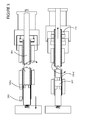
- Fig. 2 shows a side view of the first embodiment of the invention shown in Fig. 1 during delivery of an implantable medical device and during release of the implantable medical device.
- rotation in one direction imparts rotational force onto the anchor element coupled with the implantable device, wherein the rotational force is transmitted from press-fit coupling element 110 to the proximal portion of the adapter to the distal portion of the adapter to the implantable device to the anchor as is shown in the top portion of the figure.
- press-fit coupling element 110 is disengaged from a corresponding cavity in the delivery sheath shown just to the left of press-fit coupling element 110 in the lower figure, which disengages rotational forces from travelling through the adapter, and which ensures that no disengagement of the anchor occurs when the adapter is uncoupled with the implantable device.
- Fig. 3 shows a side view of a second embodiment of the invention during delivery of an implantable medical device and during release of the implantable medical device.
- This embodiment of the adapter may utilize faceted head 105d wherein the implantable device includes a corresponding faceted element 105c to enable the adapter to impart the rotational force to rotate the implantable device via the faceted head.
- One or more embodiments of the adapter may include seal 310 wherein the adapter includes a hollow portion for example in the center portion of faceted head 105d, wherein the faceted head is configured to disengage from the implantable device when the hollow portion of the adapter is filled with liquid 301 introduced between faceted element 105c and faceted head 105d, for example in location 302.
- press-fit coupling element 110 at the proximal end is disengaged as the adapter is filled with liquid in location 302 so that the press-fit coupling element no longer presses against the side of the adapter. This disables rotational forces from rotating the distal end of the adapter.
- liquid 301 may be of a temperature that alters the physical properties of the force-fit or rotational elements which may be may of temperature dependent materials such as nitinol for example, so that the adapter either disengages the leadless device or disables rotation of the leadless device or both.
- Fig. 4 shows a side view of a third embodiment of the invention having an adapter that includes ball and ramp 105f at the distal end 402 coupled with at least one wire 401 within the adapter wherein the at least one wire is configured to enable the adapter to rotate when the rotational force is applied to the at least one wire near the proximal end of the adapter.
- a helix or double helix may be utilized as the at least one wire 401 to provide the rotational force within the adapter.
- Any mechanism at the proximal side of the adapter may be utilized to impart the rotational force including manual or automated mechanisms for example.
- the implantable device includes a corresponding rotational element 105e to enable the adapter to impart the rotational force to rotate the implantable device via the ball and ramp.
- the ball and ramp are configured to disengage the adapter from the implantable device when longitudinal force is applied in a direction away from the implantable device, for example when enough force is applied to overcome the lateral force applied by the ball to a corresponding element on the implantable device.
Landscapes
- Health & Medical Sciences (AREA)
- Life Sciences & Earth Sciences (AREA)
- Public Health (AREA)
- General Health & Medical Sciences (AREA)
- Nuclear Medicine, Radiotherapy & Molecular Imaging (AREA)
- Engineering & Computer Science (AREA)
- Biomedical Technology (AREA)
- Veterinary Medicine (AREA)
- Animal Behavior & Ethology (AREA)
- Surgery (AREA)
- Radiology & Medical Imaging (AREA)
- Molecular Biology (AREA)
- Pathology (AREA)
- Medical Informatics (AREA)
- Heart & Thoracic Surgery (AREA)
- Prostheses (AREA)
- Electrotherapy Devices (AREA)
Abstract
Description
- At least one embodiment of the invention generally relates to an apparatus for implantation of medical devices and more particularly, but not by way of limitation, relates to a leadless implantable device delivery apparatus.
- Implantable medical devices may be implanted in patients in need of cardiac monitoring and if necessary, electrical stimulation. Leadless implantable devices, such as a leadless pacemaker for example have been developed to eliminate problems associated with electrode leads, which are prone to failure over time. In addition, explantation of electrode leads that have been implanted for long periods of time increases the risk of complications. Electrical energy is sensed via the implantable device and analyzed locally or with an associated implantable medical device, or external device through wireless communications for example. Therapeutic energy is provided by the implantable device, for example in a heart to ensure that the heart provides life-sustaining contractions that pump blood through the patient's body. Generally, the leadless implantable devices are physically attached to the heart in a manner that is intended to be relatively permanent, so as to ensure long term robust electrical contact with the specific heart tissue and in addition to avoid disengagement, which may lead to problems in the lungs if the leadless implantable device detaches from the tissue. Typical leadless implantable devices provide attachment mechanisms such as screws or tines that project in one way or another into the tissue of the heart.
- Implantation of leadless implantable devices may be performed in a variety of ways, for example via the femoral vein. Advantages of this type of implantation include minimization of infection and reduction in the amount of X-rays in the implantation process. In addition, this type of implantation minimizes the surgical procedures involved, for example since no surgical pocket is required to house an implantable device with leads that extend to the heart. This type of implantation also minimizes the amount of time that a patient must remain in the hospital. However, the disadvantages are that the leadless implantable devices currently implanted are difficult to position at an optimal implantation site, and once implanted, generally with hooks, these types of devices are generally abandoned when their battery life is exhausted since their implantation is intended to be permanent.
- At least one embodiment of the invention provides a leadless implantable device delivery apparatus that for example enables testing of an implantation site before permanent implantation and enables secure attachment of a leadless implantable device at the site while minimizing effects of the implantation procedure.
- Embodiments of the invention generally include a delivery sheath that generally encloses an adapter. The delivery sheath is configured to accommodate, house or otherwise couple with the leadless implantable device. The leadless implantable device includes or is otherwise coupled with an anchor having at least one projection configured to physically attach the anchor to tissue, for example heart tissue. The adapter is configured to impart rotational force at the distal end of the adapter that is applied to the proximal end of the adapter to rotate the leadless implantable device and/or anchor coupled therewith.
- Embodiments of the adapter may include a press-fit coupling element at the proximal end that is configured to press against a side of the adapter to enable the adapter to rotate when the rotational force is applied. This provides sufficient torque to implant a rotational type anchor.
- With respect to the implantable device, embodiments of the adapter may include a force-fit coupling element at the distal end that is configured to couple with a side of the implantable device to enable the implantable device to rotate when the rotational force is applied. Embodiments of the force-fit coupling element at the distal end may be configured to couple with a side of the implantable device to enable the implantable device to disengage from the adapter when an opposing rotational force with respect to the rotational force is applied. In one or more embodiments, the force-fit element may include at least one pin, wherein the implantable device includes at least one indentation configured to couple with the pin to enable the adapter to impart the rotational force to rotate the implantable device via the pin. Any other force-fit element and corresponding device on the implantable device may be utilized in keeping with the spirit of the invention, as one skilled in the art will recognize.
- During delivery of the leadless implantable device, rotation in one direction imparts rotational force onto the anchor element coupled with the implantable device, wherein the rotational force is transmitted from the press-fit coupling element to the proximal portion of the adapter to the distal portion of the adapter to the implantable device to the anchor. During release, the press-fit coupling element is disengaged from a corresponding cavity in the delivery sheath, which disables rotational forces from travelling through or otherwise along the adapter, and which ensures that no disengagement of the anchor occurs when the adapter is uncoupled from the implantable device.
- Other embodiments of the adapter may utilize a faceted head, for example a hex nut or any other shape that allows rotational forces to be applied to the leadless implantable device. Generally, the implantable device includes a corresponding faceted element to enable the adapter to impart the rotational force to rotate the implantable device via the faceted head. One or more embodiments of the adapter may include a seal wherein the adapter includes a hollow portion for example in the center portion of the faceted head, wherein the faceted head is configured to disengage from the implantable device when the hollow portion of the adapter is filled with liquid introduced between the faceted element and faceted head. In one or more embodiments, the press-fit coupling element at the proximal end is disengaged as the adapter is filled with liquid so that the press-fit coupling element no longer presses against the side of the adapter. This disables rotational forces from rotating the distal end of the adapter.
- Other embodiments of the adapter may utilize a ball and ramp at the distal end coupled with at least one wire within the adapter wherein the at least one wire is configured to enable the adapter to rotate when the rotational force is applied to the at least one wire near the proximal end of the adapter. In one embodiment a helix or double helix may be utilized as the at least one wire to provide the rotational force within the adapter. Any mechanism at the proximal side of the adapter may be utilized to impart the rotational force including manual or automated mechanisms for example. In one or more embodiments, the implantable device includes a corresponding rotational element to enable the adapter to impart the rotational force to rotate the implantable device via the ball and ramp. In one or more embodiments, the ball and ramp are configured to disengage the adapter from the implantable device when longitudinal force is applied in a direction away from the implantable device, for example when enough force is applied to overcome the lateral force applied by the ball to a corresponding element on the implantable device.
- The above and other aspects, features and advantages of at least one embodiment of the invention will be more apparent from the following more particular description thereof, presented in conjunction with the following drawings wherein:
- Fig. 1
- shows a side view of a first embodiment of the invention, along with a view of the distal end of the adapter and a first embodiment of a force-fit element.
- Fig. 2
- shows a side view of the first embodiment of the invention shown in
Fig. 1 during delivery of an implantable medical device and during release of the implantable medical device. - Fig. 3
- shows a side view of a second embodiment of the invention during delivery of an implantable medical device and during release of the implantable medical device.
- Fig. 4
- shows a side view of a third embodiment of the invention.
- The following description is of the best mode presently contemplated for carrying out at least one embodiment of the invention. This description is not to be taken in a limiting sense, but is made merely for the purpose of describing the general principles of the invention. The scope of the invention should be determined with reference to the claims.
-
Fig. 1 shows a side view of a first embodiment of the leadless implantabledevice delivery apparatus 100, along with a view of the distal end of theadapter 102 belowapparatus 100 and a side view of a first embodiment of force-fit element 105b shown belowadapter 102, wherein the force-fit element is configured to couple with the side ofimplantable device 103, for example via force-fit groove 105a. Embodiments of the invention generally includedelivery sheath 101, shown as a distal portion on the left and proximal portion on the right wherein the broken lines show an arbitrary length of a single delivery sheath. Embodiments ofdelivery sheath 101 are configured to accommodate leadlessimplantable device 103 havinganchor 104 that includes at least one projection configured to physically attach the anchor to tissue, for example heart tissue. In addition, embodiments of the invention utilizeadapter 102 having a distal end and a proximal end, shown on the left and right respectively, wherein the adapter is configured to reside withindelivery sheath 101 and wherein the adapter is configured to impart rotational force at the distal end of the adapter that is applied to the proximal end of theadapter 102 to rotateimplantable device 103. - Embodiments of the adapter may include press-
fit coupling element 110 at the proximal end that is configured to press against a side of the adapter to enable the adapter to rotate when the rotational force is applied. This provides sufficient torque to implant a rotational type anchor. From the viewpoint of the implantable device, embodiments of the adapter may include force-fit coupling element 105b at the distal end that is configured to couple with a side of the implantable device to enable the implantable device to rotate when the rotational force is applied. Embodiments of the force-fit coupling element at the distal end may be configured to couple with a side of said implantable device to enable the implantable device to disengage from the adapter when an opposing rotational force with respect to the rotational force is applied. - In one or more embodiments, the force-fit element may include at least one
pin 105b, wherein the implantable device includes at least oneindentation 105a configured to couple with the pin to enable the adapter to impart the rotational force to rotate theimplantable device 103 via the pin. Any other force-fit element and corresponding device on the implantable device may be utilized in keeping with the spirit of the invention, as one skilled in the art will recognize. -
Fig. 2 shows a side view of the first embodiment of the invention shown inFig. 1 during delivery of an implantable medical device and during release of the implantable medical device. During delivery, rotation in one direction imparts rotational force onto the anchor element coupled with the implantable device, wherein the rotational force is transmitted from press-fit coupling element 110 to the proximal portion of the adapter to the distal portion of the adapter to the implantable device to the anchor as is shown in the top portion of the figure. During release, press-fit coupling element 110 is disengaged from a corresponding cavity in the delivery sheath shown just to the left of press-fit coupling element 110 in the lower figure, which disengages rotational forces from travelling through the adapter, and which ensures that no disengagement of the anchor occurs when the adapter is uncoupled with the implantable device. -
Fig. 3 shows a side view of a second embodiment of the invention during delivery of an implantable medical device and during release of the implantable medical device. This embodiment of the adapter may utilize facetedhead 105d wherein the implantable device includes a corresponding facetedelement 105c to enable the adapter to impart the rotational force to rotate the implantable device via the faceted head. One or more embodiments of the adapter may includeseal 310 wherein the adapter includes a hollow portion for example in the center portion of facetedhead 105d, wherein the faceted head is configured to disengage from the implantable device when the hollow portion of the adapter is filled withliquid 301 introduced between facetedelement 105c and facetedhead 105d, for example inlocation 302. In one or more embodiments, press-fit coupling element 110 at the proximal end is disengaged as the adapter is filled with liquid inlocation 302 so that the press-fit coupling element no longer presses against the side of the adapter. This disables rotational forces from rotating the distal end of the adapter. In one or more embodiments, liquid 301 may be of a temperature that alters the physical properties of the force-fit or rotational elements which may be may of temperature dependent materials such as nitinol for example, so that the adapter either disengages the leadless device or disables rotation of the leadless device or both. -
Fig. 4 shows a side view of a third embodiment of the invention having an adapter that includes ball and ramp 105f at thedistal end 402 coupled with at least onewire 401 within the adapter wherein the at least one wire is configured to enable the adapter to rotate when the rotational force is applied to the at least one wire near the proximal end of the adapter. In one embodiment a helix or double helix may be utilized as the at least onewire 401 to provide the rotational force within the adapter. Any mechanism at the proximal side of the adapter may be utilized to impart the rotational force including manual or automated mechanisms for example. In one or more embodiments, the implantable device includes a correspondingrotational element 105e to enable the adapter to impart the rotational force to rotate the implantable device via the ball and ramp. In one or more embodiments, the ball and ramp are configured to disengage the adapter from the implantable device when longitudinal force is applied in a direction away from the implantable device, for example when enough force is applied to overcome the lateral force applied by the ball to a corresponding element on the implantable device.
Claims (11)
- A leadless implantable device delivery apparatus (100) comprising:a delivery sheath (101) configured to accommodate a leadless implantable device (103) having an anchor (104) comprising at least one projection configured to physically attach said anchor to tissue;an adapter (102) having a proximal end and a distal end, wherein said adapter is configured to reside within said delivery sheath and wherein said adapter is configured to impart rotational force at said distal end of said adapter that is applied to said proximal end of said adapter to rotate said implantable device.
- The leadless implantable device delivery apparatus (100) according to claim 1, wherein said adapter (102) comprises a press-fit coupling element (110) at said proximal end configured to press against a side of said adapter to enable said adapter to rotate when said rotational force is applied.
- The leadless implantable device delivery apparatus (100) according to claim 1 or 2, wherein said adapter (102) comprises a force-fit coupling element (105b) at said distal end configured to couple with a side of said implantable device to enable said implantable device to rotate when said rotational force is applied.
- The leadless implantable device delivery apparatus (100) according to any of claims 1 to 3, wherein said adapter (102) comprises a force-fit coupling element (105b) at said distal end configured to couple with a side of said implantable device to enable said implantable device to disengage from said adapter when an opposing rotational force with respect to said rotational force is applied.
- The leadless implantable device delivery apparatus (100) according to any of claims 1 to 4, wherein said adapter (102) comprises a temperature dependent force-fit coupling element (105b) at said distal end configured to couple with a side of said implantable device to enable said implantable device to disengage from said adapter when a temperature is applied that alters a physical property of said temperature dependent force-fit coupling element.
- The leadless implantable device delivery apparatus (100) according to any of claims 1 to 5, wherein
said adapter (102) comprises at least one pin (105a);
said implantable device (103) comprising at least one indentation (105a) configured to couple with said pin to enable said adapter to impart said rotational force to rotate said implantable device via said pin. - The leadless implantable device delivery apparatus (100) according to any of claims 1 to 6, wherein
said adapter (102) comprises a faceted head (105d);
said implantable device (103) comprising a corresponding faceted element (105c) to enable said adapter to impart said rotational force to rotate said implantable device via said faceted head. - The leadless implantable device delivery apparatus according (100) to claim 7, wherein said adapter (102) comprises a seal (310) and wherein said adapter comprises a hollow portion and wherein said faceted head (105d) is configured to disengage said implantable device (103) when said hollow portion of said adapter is filled with liquid.
- The leadless implantable device delivery apparatus (100) according to claim 8, wherein said press-fit coupling element (110) at said proximal end is disengaged as said adapter (102) is filled with said liquid so that said press-fit coupling element no longer presses against said side of said adapter to disable said rotational force to rotate a distal end of said adapter.
- The leadless implantable device delivery apparatus (106) according to claim 1,
wherein
said adapter (102) comprises a ball and ramp (105f) at said distal end coupled with at least one wire (401) within said adapter wherein said at least one wire is configured to enable said adapter to rotate when said rotational force is applied to said at least one wire near said proximal end of said adapter;
said implantable device (103) comprising a corresponding rotational element (105e) to enable said adapter to impart said rotational force to rotate said implantable device via said ball and ramp. - A leadless implantable device delivery apparatus (100) according to claim 10 wherein said ball and ramp (105f) are configured to disengage from said adapter (102) when longitudinal force is applied in a direction away from said implantable device (103).
Applications Claiming Priority (1)
| Application Number | Priority Date | Filing Date | Title |
|---|---|---|---|
| US201261730058P | 2012-11-27 | 2012-11-27 |
Publications (1)
| Publication Number | Publication Date |
|---|---|
| EP2735327A1 true EP2735327A1 (en) | 2014-05-28 |
Family
ID=49517275
Family Applications (1)
| Application Number | Title | Priority Date | Filing Date |
|---|---|---|---|
| EP20130190458 Withdrawn EP2735327A1 (en) | 2012-11-27 | 2013-10-28 | Leadless implantable device delivery apparatus |
Country Status (2)
| Country | Link |
|---|---|
| US (1) | US9238145B2 (en) |
| EP (1) | EP2735327A1 (en) |
Cited By (1)
| Publication number | Priority date | Publication date | Assignee | Title |
|---|---|---|---|---|
| CN106852124A (en) * | 2014-10-22 | 2017-06-13 | 心脏起搏器股份公司 | For the delivery device and method of leadless cardiac equipment |
Families Citing this family (118)
| Publication number | Priority date | Publication date | Assignee | Title |
|---|---|---|---|---|
| US10071243B2 (en) | 2013-07-31 | 2018-09-11 | Medtronic, Inc. | Fixation for implantable medical devices |
| WO2015023474A1 (en) | 2013-08-16 | 2015-02-19 | Cardiac Pacemakers, Inc. | Leadless cardiac pacemaker and retrieval device |
| US10842993B2 (en) | 2013-08-16 | 2020-11-24 | Cardiac Pacemakers, Inc. | Leadless cardiac pacing devices |
| ES2666373T3 (en) | 2013-08-16 | 2018-05-04 | Cardiac Pacemakers, Inc. | Management devices for wireless heart devices |
| US9480850B2 (en) | 2013-08-16 | 2016-11-01 | Cardiac Pacemakers, Inc. | Leadless cardiac pacemaker and retrieval device |
| US10179236B2 (en) | 2013-08-16 | 2019-01-15 | Cardiac Pacemakers, Inc. | Leadless cardiac pacing devices |
| US9492674B2 (en) | 2013-08-16 | 2016-11-15 | Cardiac Pacemakers, Inc. | Leadless cardiac pacemaker with delivery and/or retrieval features |
| US9393427B2 (en) | 2013-08-16 | 2016-07-19 | Cardiac Pacemakers, Inc. | Leadless cardiac pacemaker with delivery and/or retrieval features |
| US10722723B2 (en) | 2013-08-16 | 2020-07-28 | Cardiac Pacemakers, Inc. | Delivery devices and methods for leadless cardiac devices |
| EP3092034B1 (en) | 2014-01-10 | 2019-10-30 | Cardiac Pacemakers, Inc. | Systems for detecting cardiac arrhythmias |
| US20150196769A1 (en) | 2014-01-10 | 2015-07-16 | Cardiac Pacemakers, Inc. | Methods and systems for improved communication between medical devices |
| WO2015168153A1 (en) | 2014-04-29 | 2015-11-05 | Cardiac Pacemakers, Inc. | Leadless cardiac pacing devices including tissue engagement verification |
| WO2015168155A1 (en) | 2014-04-29 | 2015-11-05 | Cardiac Pacemakers, Inc. | Leadless cardiac pacemaker with retrieval features |
| US9526909B2 (en) | 2014-08-28 | 2016-12-27 | Cardiac Pacemakers, Inc. | Medical device with triggered blanking period |
| US9956400B2 (en) | 2014-10-22 | 2018-05-01 | Cardiac Pacemakers, Inc. | Delivery devices and methods for leadless cardiac devices |
| WO2016126613A1 (en) | 2015-02-06 | 2016-08-11 | Cardiac Pacemakers, Inc. | Systems and methods for treating cardiac arrhythmias |
| WO2016126968A1 (en) | 2015-02-06 | 2016-08-11 | Cardiac Pacemakers, Inc. | Systems and methods for safe delivery of electrical stimulation therapy |
| WO2016130477A2 (en) | 2015-02-09 | 2016-08-18 | Cardiac Pacemakers, Inc. | Implantable medical device with radiopaque id tag |
| CN107530002B (en) | 2015-03-04 | 2021-04-30 | 心脏起搏器股份公司 | System and method for treating cardiac arrhythmias |
| EP3270768B1 (en) | 2015-03-18 | 2023-12-13 | Cardiac Pacemakers, Inc. | Communications in a medical device system with link quality assessment |
| US10050700B2 (en) | 2015-03-18 | 2018-08-14 | Cardiac Pacemakers, Inc. | Communications in a medical device system with temporal optimization |
| US10357159B2 (en) | 2015-08-20 | 2019-07-23 | Cardiac Pacemakers, Inc | Systems and methods for communication between medical devices |
| EP3337558B1 (en) | 2015-08-20 | 2025-05-28 | Cardiac Pacemakers, Inc. | Methods for communication between medical devices |
| US9956414B2 (en) | 2015-08-27 | 2018-05-01 | Cardiac Pacemakers, Inc. | Temporal configuration of a motion sensor in an implantable medical device |
| US9968787B2 (en) | 2015-08-27 | 2018-05-15 | Cardiac Pacemakers, Inc. | Spatial configuration of a motion sensor in an implantable medical device |
| CN108136189B (en) | 2015-08-28 | 2021-10-15 | 心脏起搏器股份公司 | System for Behavioral Response Signal Detection and Therapeutic Delivery |
| WO2017040115A1 (en) | 2015-08-28 | 2017-03-09 | Cardiac Pacemakers, Inc. | System for detecting tamponade |
| US10226631B2 (en) | 2015-08-28 | 2019-03-12 | Cardiac Pacemakers, Inc. | Systems and methods for infarct detection |
| US10092760B2 (en) | 2015-09-11 | 2018-10-09 | Cardiac Pacemakers, Inc. | Arrhythmia detection and confirmation |
| CN108136185B (en) | 2015-10-08 | 2021-08-31 | 心脏起搏器股份公司 | Apparatus and method for adjusting pacing rate in an implantable medical device |
| CN108348758B (en) | 2015-11-20 | 2022-04-12 | 心脏起搏器股份公司 | Delivery devices and methods for leadless cardiac devices |
| CN108348759B (en) | 2015-11-20 | 2021-08-17 | 心脏起搏器股份公司 | Delivery devices and methods for leadless cardiac devices |
| JP6608063B2 (en) | 2015-12-17 | 2019-11-20 | カーディアック ペースメイカーズ, インコーポレイテッド | Implantable medical device |
| US10905886B2 (en) | 2015-12-28 | 2021-02-02 | Cardiac Pacemakers, Inc. | Implantable medical device for deployment across the atrioventricular septum |
| US10583303B2 (en) | 2016-01-19 | 2020-03-10 | Cardiac Pacemakers, Inc. | Devices and methods for wirelessly recharging a rechargeable battery of an implantable medical device |
| US10463853B2 (en) | 2016-01-21 | 2019-11-05 | Medtronic, Inc. | Interventional medical systems |
| US10099050B2 (en) | 2016-01-21 | 2018-10-16 | Medtronic, Inc. | Interventional medical devices, device systems, and fixation components thereof |
| WO2017136548A1 (en) | 2016-02-04 | 2017-08-10 | Cardiac Pacemakers, Inc. | Delivery system with force sensor for leadless cardiac device |
| CN108883286B (en) | 2016-03-31 | 2021-12-07 | 心脏起搏器股份公司 | Implantable medical device with rechargeable battery |
| US10350408B2 (en) | 2016-04-28 | 2019-07-16 | Medtronic, Inc. | Interventional medical systems, associated assemblies and methods |
| US10143823B2 (en) | 2016-04-29 | 2018-12-04 | Medtronic, Inc. | Interventional medical systems and improved assemblies thereof and associated methods of use |
| US10668294B2 (en) | 2016-05-10 | 2020-06-02 | Cardiac Pacemakers, Inc. | Leadless cardiac pacemaker configured for over the wire delivery |
| US10328272B2 (en) | 2016-05-10 | 2019-06-25 | Cardiac Pacemakers, Inc. | Retrievability for implantable medical devices |
| US10300287B2 (en) | 2016-06-27 | 2019-05-28 | Medtronic, Inc. | Delivery systems for implantable medical devices, and associated tethering assemblies and methods |
| EP3474945B1 (en) | 2016-06-27 | 2022-12-28 | Cardiac Pacemakers, Inc. | Cardiac therapy system using subcutaneously sensed p-waves for resynchronization pacing management |
| US11207527B2 (en) | 2016-07-06 | 2021-12-28 | Cardiac Pacemakers, Inc. | Method and system for determining an atrial contraction timing fiducial in a leadless cardiac pacemaker system |
| WO2018009392A1 (en) | 2016-07-07 | 2018-01-11 | Cardiac Pacemakers, Inc. | Leadless pacemaker using pressure measurements for pacing capture verification |
| EP3487579B1 (en) | 2016-07-20 | 2020-11-25 | Cardiac Pacemakers, Inc. | System for utilizing an atrial contraction timing fiducial in a leadless cardiac pacemaker system |
| US10391319B2 (en) | 2016-08-19 | 2019-08-27 | Cardiac Pacemakers, Inc. | Trans septal implantable medical device |
| EP3503799B1 (en) | 2016-08-24 | 2021-06-30 | Cardiac Pacemakers, Inc. | Integrated multi-device cardiac resynchronization therapy using p-wave to pace timing |
| EP3503970B1 (en) | 2016-08-24 | 2023-01-04 | Cardiac Pacemakers, Inc. | Cardiac resynchronization using fusion promotion for timing management |
| WO2018057318A1 (en) | 2016-09-21 | 2018-03-29 | Cardiac Pacemakers, Inc. | Leadless stimulation device with a housing that houses internal components of the leadless stimulation device and functions as the battery case and a terminal of an internal battery |
| US10994145B2 (en) | 2016-09-21 | 2021-05-04 | Cardiac Pacemakers, Inc. | Implantable cardiac monitor |
| US10758737B2 (en) | 2016-09-21 | 2020-09-01 | Cardiac Pacemakers, Inc. | Using sensor data from an intracardially implanted medical device to influence operation of an extracardially implantable cardioverter |
| US10765871B2 (en) | 2016-10-27 | 2020-09-08 | Cardiac Pacemakers, Inc. | Implantable medical device with pressure sensor |
| WO2018081237A1 (en) | 2016-10-27 | 2018-05-03 | Cardiac Pacemakers, Inc. | Use of a separate device in managing the pace pulse energy of a cardiac pacemaker |
| CN109922860B (en) | 2016-10-27 | 2023-07-04 | 心脏起搏器股份公司 | Implantable medical device delivery system with integrated sensors |
| US10413733B2 (en) | 2016-10-27 | 2019-09-17 | Cardiac Pacemakers, Inc. | Implantable medical device with gyroscope |
| WO2018081275A1 (en) | 2016-10-27 | 2018-05-03 | Cardiac Pacemakers, Inc. | Multi-device cardiac resynchronization therapy with timing enhancements |
| WO2018081133A1 (en) | 2016-10-27 | 2018-05-03 | Cardiac Pacemakers, Inc. | Implantable medical device having a sense channel with performance adjustment |
| CN109890456B (en) | 2016-10-31 | 2023-06-13 | 心脏起搏器股份公司 | System for activity level pacing |
| CN109952128B (en) | 2016-10-31 | 2023-06-13 | 心脏起搏器股份公司 | System for activity level pacing |
| US10583301B2 (en) | 2016-11-08 | 2020-03-10 | Cardiac Pacemakers, Inc. | Implantable medical device for atrial deployment |
| WO2018089308A1 (en) | 2016-11-09 | 2018-05-17 | Cardiac Pacemakers, Inc. | Systems, devices, and methods for setting cardiac pacing pulse parameters for a cardiac pacing device |
| CN109982738B (en) | 2016-11-21 | 2021-06-22 | 心脏起搏器股份公司 | Delivery device and wall attachment sensing |
| WO2018094344A2 (en) | 2016-11-21 | 2018-05-24 | Cardiac Pacemakers, Inc | Leadless cardiac pacemaker with multimode communication |
| US10639486B2 (en) | 2016-11-21 | 2020-05-05 | Cardiac Pacemakers, Inc. | Implantable medical device with recharge coil |
| US10881869B2 (en) | 2016-11-21 | 2021-01-05 | Cardiac Pacemakers, Inc. | Wireless re-charge of an implantable medical device |
| US11198013B2 (en) | 2016-11-21 | 2021-12-14 | Cardiac Pacemakers, Inc. | Catheter and leadless cardiac devices including electrical pathway barrier |
| EP3541472B1 (en) | 2016-11-21 | 2023-06-07 | Cardiac Pacemakers, Inc. | Implantable medical device with a magnetically permeable housing and an inductive coil disposed about the housing |
| CN109982746B (en) | 2016-11-21 | 2023-04-04 | 心脏起搏器股份公司 | Leadless cardiac pacemaker providing cardiac resynchronization therapy |
| AU2017387024B2 (en) | 2016-12-27 | 2020-04-09 | Cardiac Pacemakers, Inc. | Leadless delivery catheter with conductive pathway |
| EP3562545B1 (en) | 2016-12-27 | 2023-11-08 | Cardiac Pacemakers, Inc. | Delivery devices and methods for leadless cardiac devices |
| US10485981B2 (en) | 2016-12-27 | 2019-11-26 | Cardiac Pacemakers, Inc. | Fixation methods for leadless cardiac devices |
| US10806931B2 (en) | 2016-12-27 | 2020-10-20 | Cardiac Pacemakers, Inc. | Delivery devices and methods for leadless cardiac devices |
| US11207532B2 (en) | 2017-01-04 | 2021-12-28 | Cardiac Pacemakers, Inc. | Dynamic sensing updates using postural input in a multiple device cardiac rhythm management system |
| CN110225779B (en) | 2017-01-26 | 2023-04-04 | 心脏起搏器股份公司 | Delivery device for leadless cardiac devices |
| EP3573706B1 (en) | 2017-01-26 | 2025-08-27 | Cardiac Pacemakers, Inc. | Intra-body device communication with redundant message transmission |
| CN110198759B (en) | 2017-01-26 | 2023-08-11 | 心脏起搏器股份公司 | Leadless implantable device with removable fasteners |
| US10029107B1 (en) | 2017-01-26 | 2018-07-24 | Cardiac Pacemakers, Inc. | Leadless device with overmolded components |
| CN110418661B (en) | 2017-03-10 | 2024-01-02 | 心脏起搏器股份公司 | Fixtures for leadless cardiac devices |
| US10737092B2 (en) | 2017-03-30 | 2020-08-11 | Cardiac Pacemakers, Inc. | Delivery devices and methods for leadless cardiac devices |
| US10905872B2 (en) | 2017-04-03 | 2021-02-02 | Cardiac Pacemakers, Inc. | Implantable medical device with a movable electrode biased toward an extended position |
| US10821288B2 (en) | 2017-04-03 | 2020-11-03 | Cardiac Pacemakers, Inc. | Cardiac pacemaker with pacing pulse energy adjustment based on sensed heart rate |
| US11577085B2 (en) | 2017-08-03 | 2023-02-14 | Cardiac Pacemakers, Inc. | Delivery devices and methods for leadless cardiac devices |
| EP3668592B1 (en) | 2017-08-18 | 2021-11-17 | Cardiac Pacemakers, Inc. | Implantable medical device with pressure sensor |
| WO2019036568A1 (en) | 2017-08-18 | 2019-02-21 | Cardiac Pacemakers, Inc. | Implantable medical device with a flux concentrator and a receiving coil disposed about the flux concentrator |
| EP3684465B1 (en) | 2017-09-20 | 2021-07-14 | Cardiac Pacemakers, Inc. | Implantable medical device with multiple modes of operation |
| US11185703B2 (en) | 2017-11-07 | 2021-11-30 | Cardiac Pacemakers, Inc. | Leadless cardiac pacemaker for bundle of his pacing |
| US11813463B2 (en) | 2017-12-01 | 2023-11-14 | Cardiac Pacemakers, Inc. | Leadless cardiac pacemaker with reversionary behavior |
| CN111432875B (en) | 2017-12-01 | 2024-04-30 | 心脏起搏器股份公司 | Method and system for detecting atrial contraction timing reference and determining cardiac intervals from a ventricular implantable leadless cardiac pacemaker |
| WO2019108837A1 (en) | 2017-12-01 | 2019-06-06 | Cardiac Pacemakers, Inc. | Methods and systems for detecting atrial contraction timing fiducials within a search window from a ventricularly implanted leadless cardiac pacemaker |
| CN111417433B (en) | 2017-12-01 | 2024-04-30 | 心脏起搏器股份公司 | Method and system for detecting atrial contraction timing reference during ventricular filling from a ventricularly implanted leadless cardiac pacemaker |
| US11529523B2 (en) | 2018-01-04 | 2022-12-20 | Cardiac Pacemakers, Inc. | Handheld bridge device for providing a communication bridge between an implanted medical device and a smartphone |
| EP3735293B1 (en) | 2018-01-04 | 2022-03-09 | Cardiac Pacemakers, Inc. | Dual chamber pacing without beat-to-beat communication |
| JP2021518192A (en) | 2018-03-23 | 2021-08-02 | メドトロニック,インコーポレイテッド | VfA cardiac resynchronization therapy |
| EP3768160B1 (en) | 2018-03-23 | 2023-06-07 | Medtronic, Inc. | Vfa cardiac therapy for tachycardia |
| WO2019183507A1 (en) | 2018-03-23 | 2019-09-26 | Medtronic, Inc. | Av synchronous vfa cardiac therapy |
| WO2020065582A1 (en) | 2018-09-26 | 2020-04-02 | Medtronic, Inc. | Capture in ventricle-from-atrium cardiac therapy |
| US11951313B2 (en) | 2018-11-17 | 2024-04-09 | Medtronic, Inc. | VFA delivery systems and methods |
| WO2020132446A1 (en) | 2018-12-21 | 2020-06-25 | Medtronic, Inc. | Delivery systems and methods for left ventricular pacing |
| US11679265B2 (en) | 2019-02-14 | 2023-06-20 | Medtronic, Inc. | Lead-in-lead systems and methods for cardiac therapy |
| US11759632B2 (en) | 2019-03-28 | 2023-09-19 | Medtronic, Inc. | Fixation components for implantable medical devices |
| CN113660977B (en) | 2019-03-29 | 2024-12-17 | 心脏起搏器股份公司 | Systems and methods for treating cardiac arrhythmias |
| CN113677390B (en) | 2019-03-29 | 2024-12-17 | 心脏起搏器股份公司 | Systems and methods for treating cardiac arrhythmias |
| US11697025B2 (en) | 2019-03-29 | 2023-07-11 | Medtronic, Inc. | Cardiac conduction system capture |
| US11213676B2 (en) | 2019-04-01 | 2022-01-04 | Medtronic, Inc. | Delivery systems for VfA cardiac therapy |
| US11712188B2 (en) | 2019-05-07 | 2023-08-01 | Medtronic, Inc. | Posterior left bundle branch engagement |
| US11305127B2 (en) | 2019-08-26 | 2022-04-19 | Medtronic Inc. | VfA delivery and implant region detection |
| US11510697B2 (en) | 2019-09-11 | 2022-11-29 | Cardiac Pacemakers, Inc. | Tools and systems for implanting and/or retrieving a leadless cardiac pacing device with helix fixation |
| WO2021050685A1 (en) | 2019-09-11 | 2021-03-18 | Cardiac Pacemakers, Inc. | Tools and systems for implanting and/or retrieving a leadless cardiac pacing device with helix fixation |
| US12201454B2 (en) | 2019-09-13 | 2025-01-21 | Medtronic, Inc. | System and method for detecting medical device delivery tool position |
| US11813466B2 (en) | 2020-01-27 | 2023-11-14 | Medtronic, Inc. | Atrioventricular nodal stimulation |
| US12543992B2 (en) | 2020-03-30 | 2026-02-10 | Medtronic, Inc. | Pacing efficacy determination using a representative morphology of external cardiac signals |
| US11911168B2 (en) | 2020-04-03 | 2024-02-27 | Medtronic, Inc. | Cardiac conduction system therapy benefit determination |
| US12605103B2 (en) | 2020-05-21 | 2026-04-21 | Medtronic, Inc. | QRS detection and bracketing |
| US12465770B2 (en) | 2020-07-31 | 2025-11-11 | Medtronic, Inc. | Coronary sinus conduction system pacing and delivery |
| US11813464B2 (en) | 2020-07-31 | 2023-11-14 | Medtronic, Inc. | Cardiac conduction system evaluation |
Citations (3)
| Publication number | Priority date | Publication date | Assignee | Title |
|---|---|---|---|---|
| WO2004064729A2 (en) * | 2003-01-15 | 2004-08-05 | Alfred E. Mann Institute For Biomedical Engineering At The University Of Southern California | Treatments for snoring using injectable neuromuscular stimulators |
| WO2005007237A1 (en) * | 2002-07-22 | 2005-01-27 | University Of Southern California | Method and apparatus for the treatment of urinary tract dysfunction |
| US20080051851A1 (en) * | 2006-08-28 | 2008-02-28 | The U.S. Government represented by the Department of Veterans Affairs and The Regents of the | Restoring cough using microstimulators |
Family Cites Families (3)
| Publication number | Priority date | Publication date | Assignee | Title |
|---|---|---|---|---|
| WO2007149841A2 (en) * | 2006-06-20 | 2007-12-27 | Aortx, Inc. | Torque shaft and torque drive |
| CA2710146C (en) * | 2007-12-21 | 2017-03-28 | Microvention, Inc. | System and method for locating detachment zone of a detachable implant |
| US10112045B2 (en) * | 2010-12-29 | 2018-10-30 | Medtronic, Inc. | Implantable medical device fixation |
-
2013
- 2013-09-24 US US14/035,824 patent/US9238145B2/en not_active Expired - Fee Related
- 2013-10-28 EP EP20130190458 patent/EP2735327A1/en not_active Withdrawn
Patent Citations (3)
| Publication number | Priority date | Publication date | Assignee | Title |
|---|---|---|---|---|
| WO2005007237A1 (en) * | 2002-07-22 | 2005-01-27 | University Of Southern California | Method and apparatus for the treatment of urinary tract dysfunction |
| WO2004064729A2 (en) * | 2003-01-15 | 2004-08-05 | Alfred E. Mann Institute For Biomedical Engineering At The University Of Southern California | Treatments for snoring using injectable neuromuscular stimulators |
| US20080051851A1 (en) * | 2006-08-28 | 2008-02-28 | The U.S. Government represented by the Department of Veterans Affairs and The Regents of the | Restoring cough using microstimulators |
Cited By (1)
| Publication number | Priority date | Publication date | Assignee | Title |
|---|---|---|---|---|
| CN106852124A (en) * | 2014-10-22 | 2017-06-13 | 心脏起搏器股份公司 | For the delivery device and method of leadless cardiac equipment |
Also Published As
| Publication number | Publication date |
|---|---|
| US20140148815A1 (en) | 2014-05-29 |
| US9238145B2 (en) | 2016-01-19 |
Similar Documents
| Publication | Publication Date | Title |
|---|---|---|
| US9238145B2 (en) | Leadless implantable device delivery apparatus | |
| US9308365B2 (en) | Detachable electrode and anchor | |
| US9610454B2 (en) | Over torque limiter for leadless implantable medical devices | |
| EP2379164B1 (en) | Implantable medical lead with a movable radiopaque marker | |
| US11779774B2 (en) | In situ implantation accessory for an autonomous intracardiac capsule | |
| US20080108904A1 (en) | Implant for securing a sensor in a vessel | |
| US7519424B2 (en) | Intravascular medical device | |
| US10172997B2 (en) | Implantable solid-liquid drug delivery apparatus, formulations, and methods of use | |
| US9889295B2 (en) | Intracardiac capsule and an implantation accessory for use with the femoral artery | |
| US20070179552A1 (en) | Intravascular medical device | |
| EP3436137A1 (en) | Extraction devices configued to extract chronically implanted medical devices | |
| EP1750612A2 (en) | Esophageal delivery system and method with position indexing | |
| CN211835839U (en) | Right side entry his/her system sheath pipe of pacing | |
| US20190246984A1 (en) | Instrumented retrievable implantable device | |
| JP2025518725A (en) | Heart Monitor Device | |
| CN121101824B (en) | A modular self-stabilizing atlantoaxial lateral mass fusion device | |
| CN219185604U (en) | Pacemaker electrode capture device | |
| CN223555335U (en) | Peripheral nerve stimulation system | |
| EP4512462A1 (en) | Biostimulator having pacing extension | |
| EP1971398B1 (en) | Intravascular medical device | |
| CN206120956U (en) | Implanted vagal stimulation ware electrode wire | |
| CN206026867U (en) | Implanted vagal stimulation ware electrode wire | |
| CN206239889U (en) | A kind of implanted vagus nerve stimulator electrode cable | |
| CN122031916A (en) | Peripheral nerve stimulation system | |
| WO2008027187A2 (en) | Adaptor for temporary pacemaker |
Legal Events
| Date | Code | Title | Description |
|---|---|---|---|
| PUAI | Public reference made under article 153(3) epc to a published international application that has entered the european phase |
Free format text: ORIGINAL CODE: 0009012 |
|
| 17P | Request for examination filed |
Effective date: 20131028 |
|
| AK | Designated contracting states |
Kind code of ref document: A1 Designated state(s): AL AT BE BG CH CY CZ DE DK EE ES FI FR GB GR HR HU IE IS IT LI LT LU LV MC MK MT NL NO PL PT RO RS SE SI SK SM TR |
|
| AX | Request for extension of the european patent |
Extension state: BA ME |
|
| R17P | Request for examination filed (corrected) |
Effective date: 20141125 |
|
| RBV | Designated contracting states (corrected) |
Designated state(s): AL AT BE BG CH CY CZ DE DK EE ES FI FR GB GR HR HU IE IS IT LI LT LU LV MC MK MT NL NO PL PT RO RS SE SI SK SM TR |
|
| 17Q | First examination report despatched |
Effective date: 20181129 |
|
| STAA | Information on the status of an ep patent application or granted ep patent |
Free format text: STATUS: THE APPLICATION IS DEEMED TO BE WITHDRAWN |
|
| 18D | Application deemed to be withdrawn |
Effective date: 20190612 |