EP2735111B1 - Spectral and temporal stealthy fiber optic communication using sampling and phase encoding detection system - Google Patents
Spectral and temporal stealthy fiber optic communication using sampling and phase encoding detection system Download PDFInfo
- Publication number
- EP2735111B1 EP2735111B1 EP12815400.2A EP12815400A EP2735111B1 EP 2735111 B1 EP2735111 B1 EP 2735111B1 EP 12815400 A EP12815400 A EP 12815400A EP 2735111 B1 EP2735111 B1 EP 2735111B1
- Authority
- EP
- European Patent Office
- Prior art keywords
- spectral
- phase
- signal
- temporal
- pulse sequence
- Prior art date
- Legal status (The legal status is an assumption and is not a legal conclusion. Google has not performed a legal analysis and makes no representation as to the accuracy of the status listed.)
- Not-in-force
Links
Images



Classifications
-
- H—ELECTRICITY
- H04—ELECTRIC COMMUNICATION TECHNIQUE
- H04L—TRANSMISSION OF DIGITAL INFORMATION, e.g. TELEGRAPHIC COMMUNICATION
- H04L9/00—Cryptographic mechanisms or cryptographic arrangements for secret or secure communications; Network security protocols
- H04L9/08—Key distribution or management, e.g. generation, sharing or updating, of cryptographic keys or passwords
- H04L9/0816—Key establishment, i.e. cryptographic processes or cryptographic protocols whereby a shared secret becomes available to two or more parties, for subsequent use
- H04L9/0852—Quantum cryptography
-
- H—ELECTRICITY
- H04—ELECTRIC COMMUNICATION TECHNIQUE
- H04B—TRANSMISSION
- H04B10/00—Transmission systems employing electromagnetic waves other than radio-waves, e.g. infrared, visible or ultraviolet light, or employing corpuscular radiation, e.g. quantum communication
- H04B10/80—Optical aspects relating to the use of optical transmission for specific applications, not provided for in groups H04B10/03 - H04B10/70, e.g. optical power feeding or optical transmission through water
- H04B10/85—Protection from unauthorised access, e.g. eavesdrop protection
-
- H—ELECTRICITY
- H04—ELECTRIC COMMUNICATION TECHNIQUE
- H04K—SECRET COMMUNICATION; JAMMING OF COMMUNICATION
- H04K1/00—Secret communication
- H04K1/006—Secret communication by varying or inverting the phase, at periodic or random intervals
-
- H—ELECTRICITY
- H04—ELECTRIC COMMUNICATION TECHNIQUE
- H04K—SECRET COMMUNICATION; JAMMING OF COMMUNICATION
- H04K1/00—Secret communication
- H04K1/04—Secret communication by frequency scrambling, i.e. by transposing or inverting parts of the frequency band or by inverting the whole band
Definitions
- the system proposed by the present invention is related to a method for encrypting fiber-optic communications in both frequency and time domains.
- the encryption method proposed by the present invention is based on encrypting the temporal phase of the pulse sequence, thereby reducing its power spectral density.
- the power spectral density of the pulse sequence bearing the information is spread in the frequency domain below the noise level by means of sampling.
- temporal phase encryption prevents the coherent addition of the various pulses in the frequency domain, so as to further reduce the signal power spectral density. This way, there is no need to transmit the signal within the bandwidth of a public user in order to spectrally conceal the signal.
- ⁇ ⁇ m ⁇ M ⁇ 1 / 2 M ⁇ 1 / 2 2 N d f ⁇ m ⁇ f rect f ⁇ m ⁇ f BW e ⁇ j ⁇ d f ⁇ m ⁇ f e j 2 ⁇ ft df
- s ⁇ A ( t ) and ⁇ A ( t ) are the analytical signal and noise terms at point 9 respectively.
Landscapes
- Engineering & Computer Science (AREA)
- Computer Networks & Wireless Communication (AREA)
- Signal Processing (AREA)
- Computer Security & Cryptography (AREA)
- Physics & Mathematics (AREA)
- Electromagnetism (AREA)
- Theoretical Computer Science (AREA)
- Optical Communication System (AREA)
Description
- The present invention relates to the field of secure optical data communication. More particularly, the invention relates to a method and system for providing spectral and temporal stealthy fiber optic communication, by using sampling and phase encoding.
- The rapid spread of optical communication systems has increased the need for proper security solutions, in order to prevent eavesdropping and jamming. Existing Spread Spectrum encryption techniques are considered to be appropriate for optical communication systems, due to their large bandwidth which enables to achieve high processing gain [1]. In addition, methods for encrypting transmission using Optical Coherent Optical Code-Division Multiple-Access (OCDMA) are proposed in [2-4]. According to these methods, the signal is encrypted in the time domain using a dispersive element which encodes the spectral phase of the signal. By implementing the approaches presented in [5,6], the temporal phase of the dispersed signal is encoded using a Temporal Phase Encoder (TPE), thereby assigning different phase to each spectral component. However, by using these encryption methods while transmitting outside the bandwidth of a public channel, the spectral concealment of the signal is not always assured since, the signal is not necessarily spectrally hidden under the noise level. If the signal is not concealed in the frequency domain, an adversary that coherently detects and samples the signal can perform Discrete Fourier Transform (DFT) and disclose the spectral amplitude of the signal. Therefore, the transmitted signal is not spectrally stealthy.
-
US 2002/150242 A1 describes a method and apparatus for secure ultrafast communications comprising a double random phase encryption, which includes phase encryption in the spatial domain and phase encryption in the frequency domain. - All the methods described above failed to propose a method and system for providing stealthy fiber optic communication, which prevents eavesdropping and jamming both in spectral and temporal domains.
- It is an object of the present invention to provide a method that allows transmitting a signal with reduced power spectral density.
- It is another object of the present invention to provide a method that allows transmitting a signal, while keeping it below the noise level in the frequency domain.
- Other objects and advantages of the invention will become apparent as the description proceeds.
- The present invention is defined by the appended claims.
- The above and other characteristics and advantages of the invention will be better understood through the following illustrative and non-limitative detailed description of preferred embodiments thereof, with reference to the appended drawings, wherein:
-
Fig. 1 illustrates an analog implementation of the proposed communication channel, according to a preferred embodiment of the invention; -
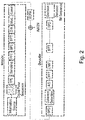
Fig. 2 illustrates a digital implementation of the proposed communication channel, according to a preferred embodiment of the invention; -
Fig. 3 illustrates the SNR after decoding for the authorized user and an adversary; -
Fig. 4 illustrates BER after decoding for the authorized user and an adversary; and -
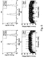
Fig. 5 illustrates the decoded pulse sequence in time and frequency domains for the authorized user and the adversary. - The system proposed by the present invention is related to a method for encrypting fiber-optic communications in both frequency and time domains. The encryption method proposed by the present invention is based on encrypting the temporal phase of the pulse sequence, thereby reducing its power spectral density. The power spectral density of the pulse sequence bearing the information is spread in the frequency domain below the noise level by means of sampling. In addition, temporal phase encryption prevents the coherent addition of the various pulses in the frequency domain, so as to further reduce the signal power spectral density. This way, there is no need to transmit the signal within the bandwidth of a public user in order to spectrally conceal the signal. Temporal spreading of the pulse sequence is achieved by spectral phase encoding, resulting in a stealthy temporal and spectral transmission. Spectral phase encryption is subsequently applied to spread the signal in the time domain and prevent the eavesdropper from observing the signal in the frequency domain by coherently adding its spectral replicas at the baseband. Hence, at the end of the encryption process, the pulse sequence is spread below the noise level in the time and frequency domains.
- According to the proposed encryption method, the spectral amplitude of the signal is deliberately spread wide, essentially enabling transmitting a signal with low power spectral density (PSD), while keeping the signal's power below the noise level in the frequency domain. The spectral spreading is achieved by sampling the signal. At the receiver, all the spectral replicas of the signal are folded to the baseband. Therefore, the PSD of the signal is reconstructed and in turn, the Signal to Noise Ratio (SNR) is improved. This is achieved by coherently adding all the signal's spectral replicas at the baseband (hence the signal is reinforced) whereas the spectral replicas of the noise are added incoherently (consequently they are averaged to a low value).
- When an
information source 11 generates a bit sequence which modulates an optical carrier with frequency fc , the modulation results in the pulse sequence s(t), which should be encrypted both in time and frequency domains. Each pulse p(t) in the sequence has a pulse width T and a double sided bandwidth Δf. The gap between two sequential pulses in the time domain is Δt, satisfying Δt ≥ T. - A digital implementation of the proposed communication system is illustrated in
Fig. 2 . For the simplicity of the mathematical analysis, an equivalent analog system is discussed and presented inFig. 1 . - At the first stage, each pulse is multiplied by a different temporal phase term. Accordingly, the addition of the Fourier Transform (FT) of the various pulses in the signal bandwidth is incoherent, thus reducing the PSD of s(t). Then, a
sampler 13 with sampling frequency Δf is applied to have M = BW / Δf spectral replicas of the signal in the frequency domain, where BW is the communication system bandwidth. An analog sampler can be implemented by a modulator that transmits a burst of the optical signal, each 1/Δf Sec. In addition, the spectral phase of the signal is optically encoded, thereby spreading the signal in the time domain. Finally, the signal's amplitude is amplified by
- The proposed decryption process begins with optical spectral phase decoding, followed by coherent detection. The signal is subsequently sampled at sampling frequency Δf in order to fold all its spectral replicas to the baseband where they are coherently added. Then, a
filter 14 matched to p(t) is applied. Finally, the temporal phase of the signal is decoded by a Temporal Phase Decoder (TPD) 19 and the signal is sampled with sampling interval Δt. The original bit sequence is recovered by adecision circuit 15. - When a bit sequence modulates an optical carrier, a pulse sequence is generated and represented by the analytical signal:


probable values 
- The temporal phase of the signal is encoded with the following phase:

- Hence, the analytical signal at
point 1 inFig. 1 resulting from the temporal phase encoding is:


- The signal is subsequently sampled, yielding the analytical signal s 2(t) at
point 2. If the bandwidth of the communication system is BW, the sampled signal has the following FT:

- Then, the spectral phase of the signal is encoded by a Spectral Phase Encoder (SPE) 16. A Fast Fourier Transform (FFT) is performed at the input to the
SPE 16 and an Inverse Fast Fourier Transform (IFFT) is performed at the output of theSPE 16. - The spectral phase encoding has two goals. The first goal is signal spreading in the time domain, in order to conceal it under the noise level. The second goal is to prevent reconstruction of the signal spectral amplitude by an eavesdropper that samples the signal in order to coherently add its spectral replicas at the baseband, while the spectral replicas of the noise are added incoherently. The spectral phase encryption turns the addition of the spectral replicas to incoherent addition. This way, the signal is kept bellow the noise level in the frequency domain.
- The phase encrypting the spectral frequency of the signal has the following form in the positive frequency domain:

- Where K = BW / δf is the number of phase bins in the communication system bandwidth and


- The spectral phase encoding can be implemented by the method described in [7] based on the one proposed in [8]. This method seems to be more suitable for the approach proposed by the present invention, rather than other methods [9-11] due to the high spectral bandwidth, resolution and addressability it enables. In addition, this spectral phase encoding makes the encryption of many Wavelength-Division Multiplexing (WDM) channels, at once, possible.
- Consequently, the spectral phase encoded analytical signal at
point 3, s 3(t) has FT:
- An Erbium doped fiber amplifier is then used to amplify the signal by

- After transmission, white Gaussian noise n(t) with autocorrelation Rn (t) = σ2 δ(t) and FT N(f) is added to the signal, due to amplifier and channel noises. Since N(f) is a white Gaussian noise with autocorrelation RN (f) = σ 2 δ(f), the noise is represented by the analytical signal nA (t) having FT 2u(f)N(f) where u(f) is the step function:

- Thus, the analytical signal s 4(t) at
point 4 is:

- The signal spreading in the time and frequency domains keeps the signal below the noise level, resulting in a stealthy signal in both domains.
- The decryption process begins with dispersion compensation followed by spectral phase decoding. Chromatic dispersion can be either compensated by dispersion compensating fibers or can be avoided by using dispersion shifted fibers for transmission. Polarization Mode Dispersion (PMD) can be compensated using the coherent method offered in [9]. The PMD compensation dynamics should be in the sub-MHz rate and thus can be compensated after the decryption process when the bit rate is reduced to Δf (which typically has the magnitude of a few GHz). Spectral phase decoding can be optically implemented by a Spectral Phase Decoder (SPD) 12, which multiplies the FT of the analytical signal with e -jψ(f). The bandwidth of the SPD is BW, giving rise to the analytical signal s 5(t) at
point 5, with FT:
- The signal is then coherently detected and passed through a low pass filter with bandwidth BW, yielding the electrical analytical signal s 6(t) at
point 6 which has FT:
- Using the following notations for the detected noise and spectral phase encoding:


- Eq. 14 can be written as:

- A sampler having a transfer function with bandwidth BW and sampling frequency Δf is subsequently applied to fold the spectral replicas of the signal to the baseband, resulting in the analytical signal s 7(t) at point 7. The FT of the signal is:

- Then, a filter matched to p(t) filters s 7(t). Consequently, the signal s 8(t) is achieved at point 8 having FT:

- Since the bandwidth of P*(f) is limited to the baseband, all the cross terms in Eq. 19 are zeroed, and therefore, only the terms with l = m are left. Thus, Eq. 19 turns to:

- Hence:

- The first term at the right side of Eq. 21 denotes the signal, whereas the right term denotes the noise. Multiplying these terms by

- The temporal phase of the signal is then decoded. Hence, the analytical signal at
point 9 is: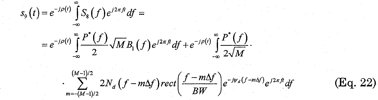
- The following notations are used:


point 9 respectively. - Eq. 23 can be further developed to yield:

- It should be noted that:


- The signal s 9(t) is sampled each temporal interval Δt, generating the sampled signal s 10(t) at point 10:

- Having the signal and noise expressed in Eq. 26 and Eq. 24 respectively, the SNR and the bit error rate (BER) measured by an authorized user after signal decryption are subsequently derived.
- The SNR of the decrypted signal is given by:


- From Eq. 26 it can be seen that:

- Assuming the SNR is measured at time t = nΔt, for which an = 1, Eq. 32 gives:

- Therefore, the signal power is:

- In addition:

- Using Eq. 24, it can be shown that E[(ñA (t))2] = E[(ñA *(t))2] = 0. Hence:

- Therefore, the SNR measured after decryption is:

- The term Ep /σ 2 is the SNR for the case of a baseband pulse sequence transmitted without going through the encoder, and simply detected by a matched filter, followed by a sampler and a decision circuit. This term is multiplied by factor M, since the M spectral replicas of the signal are added coherently, while the addition of the M spectral shifts of the noise is incoherent. The
factor 2 at the denominator is due to the modulation of the baseband signal with the optical carrier having frequency fc , which doubles the transmission bandwidth, and therefore, doubles the noise power, as well. - Before decryption, the signal is hidden below the noise level in the time domain, since low power original (i.e. unencrypted) pulses can be used due to the processing gain (which is given in Eq. 37, to increase the SNR of the decrypted signal by factor M for the case of an authorized user) resulting from the coherent addition of the signal's spectral replicas. In addition, the signal's peak power is further lowered since it is spread in the time domain due to the spectral phase encryption. If the sampled signal at
point 2 inFig. 1 has a bandwidth BW and the spectral phase code resolution is δf, there are BW/δf chips in the frequency domain, which results in spreading the samples in the time domain by factor BW/δf. Since the Erbium Doped Fiber Amplifier (EDFA) 18 amplifies the sampled signal by a factor M, the peak power of the samples will be lowered by factor BW/(M·δf)=Δf/δf, where Δf is the bandwidth of the original pulse. Since the original signal is wider than its samples by factor M in the time domain, its peak power is lowered by factor Δf/(M·δf) due to the spectral phase encoding. - Since the decoder is a linear system, the noise after the decryption process remains Gaussian. The average of the sampled noise at
point 10 inFig. 1 is:
- The variance of the noise is given by Eq. 36.
- The BER for the case of a Gaussian noise is given by:

- Using Eq. (37), the BER is:

- If an optical signal is processed by a spectrum analyzer and coherent detection yields the electrical signal v(t) (measured in Volts), the FT of v(t) is V(f). The PSD of v(t) is:

- The motivation for this definition is that df = 1/T̃ is the spectral resolution of the signal v(t). Hence, the voltage content of the signal in frequency f can be found by locating a BPF with
bandwidth 1/T̃ at frequency f. The amplitude of the filtered signal, passing through an envelope detector will be V(f)df = V(f)/T̃ (measured in Volts). Its power will be Pv (f) = |V(f)df|2 = |V(f)/T̃|2 (measured in Watts, assuming that the load over which the voltage of the signal was measured has 1Ω resistance). Pv (f) is the power content of v(t) within bandwidth df = 1/T̃ in frequency f which is measured by the spectrum analyzer. The PSD in frequency f is therefore
- It is required to estimate the PSD of the signal and the noise measured by an adversary trying to reveal the cloaked signal in the frequency domain by means of coherently detecting and sampling the signal, in order to fold its spectral replicas to the baseband. Ensuring a stealthy transmission in the frequency domain is an advantage of the proposed method over the prior art methods described in [2-6]. According to Eq. 1, the duration of the pulse sequence is T̃ = NΔt.
- The encrypted signal was shown in Eq. 12 to be:

- Applying a band pass filter (BPF) with bandwidth BW at the carrier frequency, the analytical signal becomes:

- Considering the finite duration of the noise in the time domain, Eq. (42) becomes:

- Coherently detecting s 4(t) and applying a low pass filter with bandwidth BW without spectral phase decryption yields the signal ŝ 5(t) with FT:

- Sampling the detected signal yields the signal ŝ 6(t) with FT:

- Finally, applying a matched filter results in the signal ŝ 7(t) having FT:

- The PSD of the signal is therefore:

- When


- The PSD of the noise is:

- In addition, Δf >> (NΔt)-1. Hence, noting f̃ ≡ f + fc , the following approximation is used:

- Thus, Eq. 49 becomes:

- Consequently, the spectral SNR measured by the eavesdropper is:

- The spectral SNR experienced by the adversary increases with |P(f)|2. Having M spectral replicas of the signal, this term can be attenuated by factor M due to the processing gain resulting from the coherent addition of the spectral replicas. Hence, taking a large number of spectral replicas allows reducing the power of the pulses in the transmitted pulse sequence. In addition, the spectral SNR decreases with σ 2 which is the white Gaussian noise double sided PSD and with Δt, which is the temporal interval between two sequential pulses. Enlarging this interval immerses the signal more deeply in the spectral noise.
- Eq. 52 implies that the spectral SNR measured by the adversary depends neither on the number of pulses in the pulse sequence, nor in the number of the signal spectral replicas. The independence of the number of pulses is achieved due to the temporal phase encryption, which prevents the coherent addition of the various pulses in the pulse sequence at the baseband. In addition, the independence of the number of spectral replicas results from the spectral phase encryption which prevents the coherent addition of the signal's spectral replicas at the baseband.
- The generated simulation realizes the system described in
Fig. 1 with the following parameters: - Number of pulses in a single analyzed pulse sequence - N = 500.
- Pulse sequence duration - 1µsec.
- Temporal gap between two sequential pulses - Δt = 2nsec.
- Temporal pulse width - T = 0.5nsec. Taking T = Δt results in degradation of the SNR and BER after decoding due to inter-symbol interference.
- Pulse bandwidth - Δf = 5GHz.
- Transmission bandwidth - BW = 80GHz (unless noted otherwise). Current analog to digital converters used for coherent detection are limited to bandwidth of about 50GHz.
- Additive white Gaussian noise double sided PSD - (σ 2 = 0.2mw/MHz.
- Quantization level of the temporal phase encoding - Qt = 64.
- Quantization level of the spectral phase encoding - Qf = 64.
- Spectral resolution of spectral phase encoding - δf = 200MHz.
- The modulating format of the pulse sequence was on-off-keying. Each pulse in the sequence has a raised cosine shape in the time domain with rolloff factor α = 0.25 [12]. The temporal and spectral phases encoding the pulse sequence are uniformly distributed between 0 and 2π.
- A sequence of one million pulses (which is composed of 2000 pulse sequences, each having N = 500 pulses) was run in order to evaluate the BER after decryption.
- The SNR used for the original baseband pulse passing through a matched filter was Ep /σ 2 = 10. The SNR and BER of the decoded pulse sequence were examined for various values of the transmission bandwidth BW. Their expected values are given in Eq. 37 and Eq. 40, respectively.
-
Fig. 3 illustrates the SNR after decoding. The theoretical SNR matches the one measured by the simulation. In addition, an adversary trying to recover the signal with randomly chosen temporal and spectral encoding phases, having the same quantization, temporal and spectral resolution as the authorized user was simulated. It is shown that the eavesdropper experiences very low SNR since signal is spread below the noise level. The SNR measured by the adversary varies with the transmission bandwidth, since various spectral slices of the Spectral Phase Encoder (SPE) 16 are used, therefore influencing the matching between the Spectral Phase Decoder (SPD) 12 of the authorized user and the eavesdropper. - The BER after decoding is illustrated in
Fig. 4 . Three graphs are used for the authorized user. The first graph denotes the theoretical BER. The second graph exhibits the BER calculated by substituting the measured SNR fromFig. 3 in Eq. 40. The third one is the BER measured by the simulation. It should be noted that the deviation of the measured BER from the two other BER graphs (the theoretical graph and the one calculated from the SNR) for the case of an authorized user with transmission bandwidth of 80GHz stems from the limited statistics of the simulation. While the expected BER is about 10-5.5, only 106 pulses are run by the simulation, hence the number of measured erroneous bits is lower than that expected by the two other graphs. The BER measured by the adversary is very high (about 0.5). The threshold chosen for the eavesdropper is half the maximal power of its received noiseless signal. -
Fig. 5 shows the decoded pulse sequence in time and frequency domains for the authorized user and the adversary. The transmission bandwidth is BW=80GHz.Fig. 5(a) and (b) present a 5nsec interval of the noiseless original pulse sequence and the noisy decoded pulse sequence passed through a matched filter for the authorized user and the eavesdropper, respectively. The eavesdropper cannot observe the signal while the authorized user can easily detect it.Fig. 5(c) and (d) exhibit the PSD normalized by 1/(NΔt), measured by the authorized user and the adversary respectively for a single pulse sequence consisting of 500 pulses. In the first case, the signal is well raised above the noise level while being significantly lower than the noise PSD for the latter due to the incoherent addition of the spectral replicas and incorrect temporal phase decoding, which prevents the coherent addition of the various temporal pulses in the frequency domain. - In order to evaluate the encryption strength the following assumptions are made:
- The SNR used for the original baseband pulse passing through a matched filter was Ep /σ 2 = 4 (corresponding to SNR=18dB and BER=10-4.5 after authorized decryption).
- The goal of the eavesdropper is to raise the signal above the noise level in either time or frequency domain.
- The eavesdropper has a-priory knowledge about the encryption and decryption method. The only parameters that should be guessed are the temporal and spectral phase codes.
- The eavesdropper tries to deduce the spectral and temporal phase codes by working with roughly quantized temporal and spectral phase codes.
- The eavesdropper needs to properly guess at least Nt and Nf temporal and spectral phases in order to reveal the signal in either time or frequency domain.
- When observing the signal, the adversary tries to refine the phase quantization of the guessed phases in order to improve the measured SNR and BER.
- The encryption strength is defined as the time interval needed to accomplish the goal of the eavesdropping process.
- The eavesdropper has the same spectral and temporal phase decoders as the authorized user. The maximal SPD's SLM update frequency of the eavesdropper is: fSLM = 1MHz.
First, we assume that the adversary begins with binary quantized temporal and spectral phases and that the temporal phase code is already known. Tries are made by the adversary to get SNR > 0dB in the time domain. Second, temporal phase quantization Qt=64 is assumed. - The simulation shows that the spectral resolution of the spectral phase code has major influence over the number of spectral phases needed for the eavesdropper to properly guess in order to reveal the signal in the time domain. Larger spectral resolution results in a higher Nf . For example, using 100 different randomly chosen spectral phase codes for the authorized user and the eavesdropper with Qf=256 (which are already commercial) and δf = 100MHz, the mean value observed for Nf was 158 with standard deviation of 33.33. Spectral phase encoding with δf = 100MHz can be achieved by using an SLM with 8µm pitch pixels (which is commercially available) instead of 15µm in the SPE proposed in [7]. Reducing the spectral phase code resolution to δf = 200MHz, the average Nf became 76 with standard deviation of 23.14.
- Nf is also affected by the number of spectral phase code quantization levels Qf. A larger Qf results in a larger Nf . For instance, when working with δf = 200MHz, Qf=2, the average required Nf reduced to 51.1 with standard deviation of 21.07.
- The time interval required for the adversary to get SNR > 0dB in the time domain is give by:

For the case of δf = 100MHz and Qf=256, substituting Nf = 125, Eq. 52 gives:
- While for δf = 200MHz and Qf=256, substituting Nf = 53, yields:

- And δf = 200MHz, Qf=2, resulting in Nf = 30 gives:

- Thus, the spectral resolution and quantization level of the phase code strongly affect the encryption strength. It should be noted that the above estimated Nf is actually a lower bound for the number of spectral phases needed to be properly guessed in order to accomplish positive SNR in the time domain since it was assumed that the temporal phase code is completely known to the adversary.
- Nt can be found by estimating the number of temporal phases needed to be properly guessed by an adversary using a binary quantized temporal phase decoder, in order to raise the signal above the noise level in the frequency domain after properly guessing Nf spectral phases with the binary quantized SPD. For example, a spectral phase code and an adversary SPD yielding Nf = 210 were chosen (δf = 100Mhz). The peak of the spectral SNR became positive at Nt = 320.
- Hence, using high resolution and highly quantized phase decoding, the encryption system can cause the eavesdropping process involving a "brute force" attack in which the temporal and spectral phase codes are randomly guessed to last a very long time interval in order to raise the signal above the noise level in time and frequency domains. This time interval is irrelevant for the eavesdropper.
- A second kind of possible attack is such that the eavesdropper is assumed to determine the original unencrypted signal known as "Chosen-plaintext attack" [13]. The encryption methods proposed in [2-4] enable the spectral phase code disclosure when the eavesdropper sends a known pulse sequence from the encoder of the authorized user when the signal is not concealed under the transmission of a public WDM user. The spectral phase of the sent pulse sequence is known to the eavesdropper, hence, the spectral phase code is revealed. The temporal phase encrypting the signal in the methods described in [5,6] can be disclosed by sending a narrowband pulse for which the effect of the dispersion is insignificant. The resulting encoded signal is the original signal having its temporal phase encoded. This way, the temporal phase code can be measured by the adversary. The spectral phase code can then be disclosed similarly to methods [2-4]. However, using the encryption method proposed by the present invention, the pulse sequence is well spread below the noise level in the frequency domain as well as in the time domain, thereby making the recovery of the spectral phase code much more difficult.
- The above examples and description have of course been provided only for the purpose of illustration, and are not intended to limit the invention in any way. As will be appreciated by the skilled person, the invention can be carried out in a great variety of ways, employing more than one technique from those described above, all without exceeding the scope of the invention.
-
- 1. A. J. Viterbi, "Spread spectrum communications - myths and realities," IEEE Commun. Mag. 17, 11-18 (1979).
- 2. B. B. Wu and E. E. Narimanov, "A method for secure communications over a public fiber-optical network," Opt. ).
- 3. K. Kravtsov, B. Wu, I. Glysk, P. R. Prucnal and E. Narimanov: "Stealth transmission over a WDM network with detection based on an all-optical thresholder", in Proceedings of IEEE Conference on Lasers and Electro-Optics (IEEE, New York, 2007), pp. 480-481.
- 4. B. Wu, A. Agarwal, I. Glesk, E. Narimanov, S. Etemad, and P. R. Prucnal, "Steganographic Fiber-Optic Transmission Using Coherent Spectral-Phase-Encoded Optical CDMA," in Conference on Lasers and Electro-Optics/Quantum Electronics and Laser Science Conference and Photonic Applications Systems Technologies, OSA Technical Digest (CD) (Optical Society of America, 2008), paper CFF5. http://www.opticsinfobase.org/abstract.cfm?URI=CLEO-2008-CFF5
- 5. Z. Wang, M. P. Fok, L. Xu, J. Chang, and P. R. Prucnal, "Improving the privacy of optical steganography with temporal phase masks," Opt. ).
- 6. Zhensen Gao, Xu Wang, Nobuyuki Kataoka, and Naoya Wada, "Stealth Transmission of Time-Domain Spectral Phase Encoded OCDMA Signal Over WDM Network," IEEE Photon. Technol. Lett. 22, 993-995 (2010).
- 7. D. Sinefeld, C. R. Doerr, and D. M. Marom, "Photonic Spectral Processor Employing Two-Dimensional WDM Channel Separation and a Phase LCoS Modulator," in Optical Fiber Communication Conference, OSA Technical Digest (CD) (Optical Society of America, 2010), paper OMP5. http://www.opticsinfobase.org/abstract.cfm?URI=OFC-2010-OMP5
- 8. D. Sinefeld and D. M. Marom, "Hybrid Guided-Wave/Free-Space Optics Photonic Spectral Processor Based on LCoS Phase Only Modulator," IEEE Photon. Technol. Lett. 22, 510-512 (2010).
- 9. Ezra Ip and Joseph M. Kahn, "Digital Equalization of Chromatic Dispersion and Polarization Mode Dispersion," Journal of Lightwave Technology 25, 2033-2043 (2007).
- 10. Xu Wang, "Novel Time Domain Spectral Phase Encoding/Decoding Technique for OCDMA Application," in International Conference on Transparent Optical Networks (IEEE, S. Miguel (Portugal), 2009), paper Th.A3.4.
- 11. Xu Wang and Naoya Wada, "Spectral phase encoding of ultra-short optical pulse in time domain for OCDMA application," Opt. ).
- 12. Daisuke Miyamoto and Hiroyuki Tsuda, "Spectral Phase Encoder Employing an Arrayed-Waveguide Grating and Phase-Shifting Structure," IEEE Photon. Technol. Lett. 19, 431-433 (2007).
- 13. J. G. Proakis and M. Salehi, Communication systems engineering (Prentice Hall, New Jersey, 1994), Chap. 8.
- 14. Yann Frauel1, Albertina Castro, Thomas J. Naughton and Bahram Javidi, "Resistance of the double random phase encryption against various attacks", Opt. ).
Claims (8)
- A method for spectral and temporal stealthy transmission of information over an optical communication channel, comprising:At the transmitting side:a) reducing the power spectral density PSD of a pulse sequence bearing said information by encrypting the temporal phase of said pulse sequence, thereby preventing the coherent addition of the frequency conversion of the temporal pulses of said pulse sequence in the frequency domain;b) spreading the power of the signal resulting from step a, in the frequency domain, to be below the noise level, by sampling the temporally phase-encrypted pulse sequence by means of a sampler;c) performing spectral phase encoding to temporally spread the pulse sequence resulting from step b and to prevent coherent addition of its spectral replicas in the frequency domain;d) transmitting the signal resulting from step c, encrypted both in time and frequency domains , such that the transmitted signal is below the noise level in both domains;at the receiving side:e) performing spectral phase decoding of a received signal corresponding to said transmitted signal;f) performing coherent detection of the signal resulting from step e;g) folding all the spectral replicas of the signal resulting from step f to the baseband by means of sampling, thereby coherently adding all its spectral replicas at the baseband and reinforcing its PSD;h) decrypting the temporal phase of the signal resulting from step g, thereby coherently adding its temporal pulses at the baseband and reconstructing its PSD andi) using a decision unit, recovering said information from the signal resulting from step h.
- A method according to claim 1, wherein said encrypting the temporal phase of said pulse sequence comprises multiplying each pulse of said pulse sequence by a different temporal phase term; after performing said sampling of the pulse sequence to obtain its spectral spreading in the frequency domain by a sampler and after performing said encoding of the spectral phase of the signal resulting from step b in order to spread its amplitude below the noise level in the time domain and to prevent coherent addition of its spectral replicas in the frequency domain, amplifying the amplitude of the signal resulting from step c, by an amplifier, to compensate for the attenuation of the spectral amplitude of said signal resulting from step c before said transmitting.
- A method according to claim 1, wherein said spectral phase decoding is an optical spectral phase decoding and wherein said method further comprises passing the added replicas through a matched filter (14), before said decrypting of the temporal phase.
- A method according to claim 3, further comprising: after performing said decrypting of the temporal phase and said reconstructing of the PSD, sampling the signal resulting from step h before performing said recovering by means of a decision circuit.
- A method according to claim 1, further comprising, at the receiving side, performing dispersion compensation before performing said spectral phase decoding.
- A method according to claim 1, wherein the sampler is analog and is implemented by a modulator that transmits a burst of the optical signal.
- A method according to claim 2, wherein the amplifier is an Erbium doped fiber amplifier (18).
- A system for spectral and temporal stealthy transmission of information over an optical communication channel, comprising:a) a transmitter that includes:a.1) a Temporal Phase Encoder (17) adapted to reduce the power spectral density PSD of a pulse sequence bearing said information by encrypting the temporal phase of said pulse sequence, thereby preventing the coherent addition of the frequency conversion of the temporal pulses of said pulse sequence in the frequency domain;a.2) a first sampler (13) adapted to spread the power of the signal resulting from the Temporal Phase Encoder, in the frequency domain, to be below the noise level, by sampling the temporally phase-encrypted pulse sequence;a.3) a Spectral Phase Encoder (16) adapted to perform spectral phase encoding to temporally spread the pulse sequence output from the first sampler and to prevent the coherent addition of its spectral replicas in the frequency domain;a.4) circuitry adapted to transmit the signal output from the Spectral Phase Encoder, encrypted both in time and frequency domains;b) a receiver that includes:b.1) a Spectral Phase Decoder (12) adapted to perform spectral phase decoding of a received signal corresponding to said transmitted signal, said Spectral Phase Decoder being followed by a coherent detector adapted to receive as input the signal output from the Spectral Phase Decoder;b.2) a sampling circuitry adapted to fold all the spectral replicas of the signal output from the coherent detector, to the baseband, thereby coherently adding all of its spectral replicas at the baseband and reinforcing its PSD; andb.3) a Temporal Phase Decoder (19), adapted to decrypt the temporal phase of the signal output from the sampling circuit and to thereby reconstruct its PSD; andb.4) a second sampler adapted to sample the signal output from the Temporal Phase Decoder and followed by a decision circuit (15) which is adapted to recover said information from the signal output from the second sampler.
Applications Claiming Priority (2)
| Application Number | Priority Date | Filing Date | Title |
|---|---|---|---|
| US201161508702P | 2011-07-18 | 2011-07-18 | |
| PCT/IL2012/000280 WO2013011500A1 (en) | 2011-07-18 | 2012-07-17 | Spectral and temporal stealthy fiber optic communication using sampling and phase encoding detection system |
Publications (3)
| Publication Number | Publication Date |
|---|---|
| EP2735111A1 EP2735111A1 (en) | 2014-05-28 |
| EP2735111A4 EP2735111A4 (en) | 2015-05-27 |
| EP2735111B1 true EP2735111B1 (en) | 2018-10-17 |
Family
ID=47557733
Family Applications (1)
| Application Number | Title | Priority Date | Filing Date |
|---|---|---|---|
| EP12815400.2A Not-in-force EP2735111B1 (en) | 2011-07-18 | 2012-07-17 | Spectral and temporal stealthy fiber optic communication using sampling and phase encoding detection system |
Country Status (3)
| Country | Link |
|---|---|
| US (1) | US9288045B2 (en) |
| EP (1) | EP2735111B1 (en) |
| WO (1) | WO2013011500A1 (en) |
Families Citing this family (18)
| Publication number | Priority date | Publication date | Assignee | Title |
|---|---|---|---|---|
| US9673920B2 (en) * | 2012-12-18 | 2017-06-06 | Department 13, LLC | Intrusion detection and radio fingerprint tracking |
| US9100047B2 (en) * | 2013-09-20 | 2015-08-04 | Intel Corporation | Method and apparatus for mitigating resonant effects within a power delivery network of a printed circuit board |
| US9917662B2 (en) * | 2014-01-22 | 2018-03-13 | Siemens Aktiengesellschaft | Digital measurement input for an electric automation device, electric automation device comprising a digital measurement input, and method for processing digital input measurement values |
| US9998255B2 (en) | 2016-05-11 | 2018-06-12 | International Business Machines Corporation | Fiber optic light intensity encryption |
| CN107733640B (en) * | 2017-08-29 | 2021-01-22 | 上海循态信息科技有限公司 | Continuous variable quantum key distribution method based on continuous random measurement basis |
| US10608673B2 (en) | 2017-12-22 | 2020-03-31 | Massachusetts Institute Of Technology | Decoding signals by guessing noise |
| US10944610B2 (en) * | 2017-12-22 | 2021-03-09 | Massachusetts Institute Of Technology | Decoding signals by guessing noise |
| GB201918218D0 (en) | 2019-12-11 | 2020-01-22 | Maynooth Univ | A method of decoding a codeword |
| US11431368B2 (en) | 2020-03-16 | 2022-08-30 | Massachusetts Institute Of Technology | Noise recycling |
| US11870459B2 (en) | 2020-06-08 | 2024-01-09 | Massachusetts Institute Of Technology | Universal guessing random additive noise decoding (GRAND) decoder |
| CN118235174A (en) | 2021-08-04 | 2024-06-21 | 库伊有限公司 | Silent speech detection |
| US12216749B2 (en) | 2021-08-04 | 2025-02-04 | Q (Cue) Ltd. | Using facial skin micromovements to identify a user |
| CN113794559A (en) * | 2021-10-11 | 2021-12-14 | 广东工业大学 | A physical layer secure communication system and method based on dispersion-phase encryption |
| CN113985681B (en) * | 2021-10-28 | 2024-02-27 | 中国科学院声学研究所南海研究站 | Time domain stealth switch and time domain stealth device based on light intensity modulator |
| CN114268471B (en) * | 2021-12-10 | 2022-10-14 | 中国科学院声学研究所南海研究站 | Optical time domain stealth and encryption device for optical communication system |
| CN114282385B (en) * | 2021-12-29 | 2024-04-09 | 中国信息通信研究院 | Image display method for hidden targets |
| KR102977850B1 (en) * | 2022-05-19 | 2026-06-15 | 서울대학교산학협력단 | Device and Method for Homomorphic Permutation |
| IL318490A (en) | 2022-07-20 | 2025-03-01 | Q Cue Ltd | Detecting and utilizing facial micromovements |
Family Cites Families (7)
| Publication number | Priority date | Publication date | Assignee | Title |
|---|---|---|---|---|
| US7447312B2 (en) | 2000-11-27 | 2008-11-04 | University Of Connecticut | Method and apparatus for secure ultrafast communication |
| US7545929B1 (en) * | 2002-10-25 | 2009-06-09 | Lockheed Martin Corporation | Analog encryption |
| US7126739B2 (en) * | 2005-02-28 | 2006-10-24 | Lucent Technologies Inc. | Method and apparatus for optical pulse characterization using simplified chronocyclic tomography |
| US7613225B1 (en) * | 2006-02-10 | 2009-11-03 | Honeywell International Inc. | System and method for secure communication of collected amphibious data |
| US7831049B1 (en) * | 2006-05-10 | 2010-11-09 | Nucrypt, LLC | Enhanced encryption method and system for ultra secure applications |
| WO2009070695A1 (en) * | 2007-11-26 | 2009-06-04 | Mayo Foundation For Medical Education And Research | System and method for phase offset and time delay correction in magnetic resonance spectroscopy data |
| US8599961B2 (en) * | 2010-10-14 | 2013-12-03 | KATREIN-Werke KG | Crest factor reduction method and circuit for a multi-carrier signal |
-
2012
- 2012-07-17 WO PCT/IL2012/000280 patent/WO2013011500A1/en not_active Ceased
- 2012-07-17 US US14/232,655 patent/US9288045B2/en not_active Expired - Fee Related
- 2012-07-17 EP EP12815400.2A patent/EP2735111B1/en not_active Not-in-force
Non-Patent Citations (1)
| Title |
|---|
| None * |
Also Published As
| Publication number | Publication date |
|---|---|
| EP2735111A4 (en) | 2015-05-27 |
| US9288045B2 (en) | 2016-03-15 |
| US20140146969A1 (en) | 2014-05-29 |
| EP2735111A1 (en) | 2014-05-28 |
| WO2013011500A1 (en) | 2013-01-24 |
Similar Documents
| Publication | Publication Date | Title |
|---|---|---|
| US9288045B2 (en) | Spectral and temporal stealthy fiber optic communication using sampling and phase encoding detection systems | |
| Karinou et al. | Toward the integration of CV quantum key distribution in deployed optical networks | |
| US20200162172A1 (en) | Physical-Layer Security for Coherent Communications System | |
| US9319137B2 (en) | Methods and systems for reduced complexity nonlinear compensation | |
| Le et al. | Demonstration of phase-conjugated subcarrier coding for fiber nonlinearity compensation in CO-OFDM transmission | |
| Zhou et al. | Multi-symbol digital signal processing techniques for discrete eigenvalue transmissions based on nonlinear Fourier transform | |
| US20130195459A1 (en) | Method and apparatus for fiber non-linearity mitigation | |
| US7620328B2 (en) | Multi-wavelength optical CDMA with differential encoding and bipolar differential detection | |
| CN102546506A (en) | Method and system for optical orthogonal frequency division multiplexing with companding transform | |
| US20070201692A1 (en) | Data transmission apparatus, data transmission method | |
| US20160087740A1 (en) | Half-cycled orthogonal frequency divisional multiplexing transmission and reception | |
| Wang et al. | 40Gbits^− 1 Data Transmission in an Installed Optical Link Encrypted Using Physical Layer Security Seeded by Quantum Key Distribution | |
| US12613128B2 (en) | Enhanced disturbance monitoring and localization enabled by digital signal processing (DSP)-based laser phase noise estimation | |
| US8538272B1 (en) | Data security in optical communications systems | |
| Zhao et al. | Transmission of 4-ASK optical fast OFDM with chromatic dispersion compensation | |
| Da Ros et al. | Impact of transmitter phase noise on NFDM transmission with discrete spectral modulation | |
| Mangone et al. | A PAPR reduction technique using Hadamard transform combined with clipping and filtering based on DCT/IDCT for IM/DD optical OFDM systems | |
| Yeminy et al. | Spectral and temporal stealthy fiber-optic communication using sampling and phase encoding | |
| Da Ros et al. | Impact of laser phase noise on nonlinear frequency division multiplexing systems | |
| Souza et al. | Spectral shuffling with phase encoding and dynamic keys applied to transparent optical network signals | |
| Wang et al. | Real-time stealth optical transmission via fast laser frequency dithering | |
| Guo et al. | A long reach IM/DD OFDM-PON using super-Nyquist image induced aliasing and code-division multiplexing | |
| Zhao et al. | Optical encryption scheme based on spectrum aliasing using a pair of filter banks | |
| Karar et al. | Polynomial pulses for mitigating fiber nonlinearity in coherent optical fiber communications | |
| Abbade et al. | All-optical phase and delay spectral encoding of signals with advanced modulation formats |
Legal Events
| Date | Code | Title | Description |
|---|---|---|---|
| PUAI | Public reference made under article 153(3) epc to a published international application that has entered the european phase |
Free format text: ORIGINAL CODE: 0009012 |
|
| 17P | Request for examination filed |
Effective date: 20140116 |
|
| AK | Designated contracting states |
Kind code of ref document: A1 Designated state(s): AL AT BE BG CH CY CZ DE DK EE ES FI FR GB GR HR HU IE IS IT LI LT LU LV MC MK MT NL NO PL PT RO RS SE SI SK SM TR |
|
| DAX | Request for extension of the european patent (deleted) | ||
| RA4 | Supplementary search report drawn up and despatched (corrected) |
Effective date: 20150424 |
|
| RIC1 | Information provided on ipc code assigned before grant |
Ipc: H04K 1/00 20060101ALI20150420BHEP Ipc: H04K 1/04 20060101AFI20150420BHEP Ipc: H04B 10/85 20130101ALI20150420BHEP |
|
| GRAP | Despatch of communication of intention to grant a patent |
Free format text: ORIGINAL CODE: EPIDOSNIGR1 |
|
| STAA | Information on the status of an ep patent application or granted ep patent |
Free format text: STATUS: GRANT OF PATENT IS INTENDED |
|
| INTG | Intention to grant announced |
Effective date: 20180507 |
|
| GRAS | Grant fee paid |
Free format text: ORIGINAL CODE: EPIDOSNIGR3 |
|
| GRAA | (expected) grant |
Free format text: ORIGINAL CODE: 0009210 |
|
| STAA | Information on the status of an ep patent application or granted ep patent |
Free format text: STATUS: THE PATENT HAS BEEN GRANTED |
|
| AK | Designated contracting states |
Kind code of ref document: B1 Designated state(s): AL AT BE BG CH CY CZ DE DK EE ES FI FR GB GR HR HU IE IS IT LI LT LU LV MC MK MT NL NO PL PT RO RS SE SI SK SM TR |
|
| REG | Reference to a national code |
Ref country code: GB Ref legal event code: FG4D |
|
| REG | Reference to a national code |
Ref country code: CH Ref legal event code: EP |
|
| REG | Reference to a national code |
Ref country code: IE Ref legal event code: FG4D |
|
| REG | Reference to a national code |
Ref country code: DE Ref legal event code: R096 Ref document number: 602012052396 Country of ref document: DE Ref country code: AT Ref legal event code: REF Ref document number: 1055257 Country of ref document: AT Kind code of ref document: T Effective date: 20181115 |
|
| REG | Reference to a national code |
Ref country code: NL Ref legal event code: MP Effective date: 20181017 |
|
| REG | Reference to a national code |
Ref country code: LT Ref legal event code: MG4D |
|
| REG | Reference to a national code |
Ref country code: AT Ref legal event code: MK05 Ref document number: 1055257 Country of ref document: AT Kind code of ref document: T Effective date: 20181017 |
|
| PG25 | Lapsed in a contracting state [announced via postgrant information from national office to epo] |
Ref country code: NL Free format text: LAPSE BECAUSE OF FAILURE TO SUBMIT A TRANSLATION OF THE DESCRIPTION OR TO PAY THE FEE WITHIN THE PRESCRIBED TIME-LIMIT Effective date: 20181017 |
|
| PG25 | Lapsed in a contracting state [announced via postgrant information from national office to epo] |
Ref country code: IS Free format text: LAPSE BECAUSE OF FAILURE TO SUBMIT A TRANSLATION OF THE DESCRIPTION OR TO PAY THE FEE WITHIN THE PRESCRIBED TIME-LIMIT Effective date: 20190217 Ref country code: FI Free format text: LAPSE BECAUSE OF FAILURE TO SUBMIT A TRANSLATION OF THE DESCRIPTION OR TO PAY THE FEE WITHIN THE PRESCRIBED TIME-LIMIT Effective date: 20181017 Ref country code: AT Free format text: LAPSE BECAUSE OF FAILURE TO SUBMIT A TRANSLATION OF THE DESCRIPTION OR TO PAY THE FEE WITHIN THE PRESCRIBED TIME-LIMIT Effective date: 20181017 Ref country code: HR Free format text: LAPSE BECAUSE OF FAILURE TO SUBMIT A TRANSLATION OF THE DESCRIPTION OR TO PAY THE FEE WITHIN THE PRESCRIBED TIME-LIMIT Effective date: 20181017 Ref country code: NO Free format text: LAPSE BECAUSE OF FAILURE TO SUBMIT A TRANSLATION OF THE DESCRIPTION OR TO PAY THE FEE WITHIN THE PRESCRIBED TIME-LIMIT Effective date: 20190117 Ref country code: LV Free format text: LAPSE BECAUSE OF FAILURE TO SUBMIT A TRANSLATION OF THE DESCRIPTION OR TO PAY THE FEE WITHIN THE PRESCRIBED TIME-LIMIT Effective date: 20181017 Ref country code: BG Free format text: LAPSE BECAUSE OF FAILURE TO SUBMIT A TRANSLATION OF THE DESCRIPTION OR TO PAY THE FEE WITHIN THE PRESCRIBED TIME-LIMIT Effective date: 20190117 Ref country code: PL Free format text: LAPSE BECAUSE OF FAILURE TO SUBMIT A TRANSLATION OF THE DESCRIPTION OR TO PAY THE FEE WITHIN THE PRESCRIBED TIME-LIMIT Effective date: 20181017 Ref country code: ES Free format text: LAPSE BECAUSE OF FAILURE TO SUBMIT A TRANSLATION OF THE DESCRIPTION OR TO PAY THE FEE WITHIN THE PRESCRIBED TIME-LIMIT Effective date: 20181017 Ref country code: LT Free format text: LAPSE BECAUSE OF FAILURE TO SUBMIT A TRANSLATION OF THE DESCRIPTION OR TO PAY THE FEE WITHIN THE PRESCRIBED TIME-LIMIT Effective date: 20181017 |
|
| PG25 | Lapsed in a contracting state [announced via postgrant information from national office to epo] |
Ref country code: PT Free format text: LAPSE BECAUSE OF FAILURE TO SUBMIT A TRANSLATION OF THE DESCRIPTION OR TO PAY THE FEE WITHIN THE PRESCRIBED TIME-LIMIT Effective date: 20190217 Ref country code: AL Free format text: LAPSE BECAUSE OF FAILURE TO SUBMIT A TRANSLATION OF THE DESCRIPTION OR TO PAY THE FEE WITHIN THE PRESCRIBED TIME-LIMIT Effective date: 20181017 Ref country code: GR Free format text: LAPSE BECAUSE OF FAILURE TO SUBMIT A TRANSLATION OF THE DESCRIPTION OR TO PAY THE FEE WITHIN THE PRESCRIBED TIME-LIMIT Effective date: 20190118 Ref country code: SE Free format text: LAPSE BECAUSE OF FAILURE TO SUBMIT A TRANSLATION OF THE DESCRIPTION OR TO PAY THE FEE WITHIN THE PRESCRIBED TIME-LIMIT Effective date: 20181017 Ref country code: RS Free format text: LAPSE BECAUSE OF FAILURE TO SUBMIT A TRANSLATION OF THE DESCRIPTION OR TO PAY THE FEE WITHIN THE PRESCRIBED TIME-LIMIT Effective date: 20181017 |
|
| REG | Reference to a national code |
Ref country code: DE Ref legal event code: R097 Ref document number: 602012052396 Country of ref document: DE |
|
| PG25 | Lapsed in a contracting state [announced via postgrant information from national office to epo] |
Ref country code: CZ Free format text: LAPSE BECAUSE OF FAILURE TO SUBMIT A TRANSLATION OF THE DESCRIPTION OR TO PAY THE FEE WITHIN THE PRESCRIBED TIME-LIMIT Effective date: 20181017 Ref country code: DK Free format text: LAPSE BECAUSE OF FAILURE TO SUBMIT A TRANSLATION OF THE DESCRIPTION OR TO PAY THE FEE WITHIN THE PRESCRIBED TIME-LIMIT Effective date: 20181017 |
|
| PLBE | No opposition filed within time limit |
Free format text: ORIGINAL CODE: 0009261 |
|
| STAA | Information on the status of an ep patent application or granted ep patent |
Free format text: STATUS: NO OPPOSITION FILED WITHIN TIME LIMIT |
|
| PG25 | Lapsed in a contracting state [announced via postgrant information from national office to epo] |
Ref country code: EE Free format text: LAPSE BECAUSE OF FAILURE TO SUBMIT A TRANSLATION OF THE DESCRIPTION OR TO PAY THE FEE WITHIN THE PRESCRIBED TIME-LIMIT Effective date: 20181017 Ref country code: SM Free format text: LAPSE BECAUSE OF FAILURE TO SUBMIT A TRANSLATION OF THE DESCRIPTION OR TO PAY THE FEE WITHIN THE PRESCRIBED TIME-LIMIT Effective date: 20181017 Ref country code: RO Free format text: LAPSE BECAUSE OF FAILURE TO SUBMIT A TRANSLATION OF THE DESCRIPTION OR TO PAY THE FEE WITHIN THE PRESCRIBED TIME-LIMIT Effective date: 20181017 Ref country code: SK Free format text: LAPSE BECAUSE OF FAILURE TO SUBMIT A TRANSLATION OF THE DESCRIPTION OR TO PAY THE FEE WITHIN THE PRESCRIBED TIME-LIMIT Effective date: 20181017 |
|
| 26N | No opposition filed |
Effective date: 20190718 |
|
| PG25 | Lapsed in a contracting state [announced via postgrant information from national office to epo] |
Ref country code: SI Free format text: LAPSE BECAUSE OF FAILURE TO SUBMIT A TRANSLATION OF THE DESCRIPTION OR TO PAY THE FEE WITHIN THE PRESCRIBED TIME-LIMIT Effective date: 20181017 |
|
| PG25 | Lapsed in a contracting state [announced via postgrant information from national office to epo] |
Ref country code: MC Free format text: LAPSE BECAUSE OF FAILURE TO SUBMIT A TRANSLATION OF THE DESCRIPTION OR TO PAY THE FEE WITHIN THE PRESCRIBED TIME-LIMIT Effective date: 20181017 |
|
| REG | Reference to a national code |
Ref country code: CH Ref legal event code: PL |
|
| PG25 | Lapsed in a contracting state [announced via postgrant information from national office to epo] |
Ref country code: TR Free format text: LAPSE BECAUSE OF FAILURE TO SUBMIT A TRANSLATION OF THE DESCRIPTION OR TO PAY THE FEE WITHIN THE PRESCRIBED TIME-LIMIT Effective date: 20181017 |
|
| REG | Reference to a national code |
Ref country code: BE Ref legal event code: MM Effective date: 20190731 |
|
| PG25 | Lapsed in a contracting state [announced via postgrant information from national office to epo] |
Ref country code: LI Free format text: LAPSE BECAUSE OF NON-PAYMENT OF DUE FEES Effective date: 20190731 Ref country code: BE Free format text: LAPSE BECAUSE OF NON-PAYMENT OF DUE FEES Effective date: 20190731 Ref country code: CH Free format text: LAPSE BECAUSE OF NON-PAYMENT OF DUE FEES Effective date: 20190731 Ref country code: LU Free format text: LAPSE BECAUSE OF NON-PAYMENT OF DUE FEES Effective date: 20190717 |
|
| PG25 | Lapsed in a contracting state [announced via postgrant information from national office to epo] |
Ref country code: IE Free format text: LAPSE BECAUSE OF NON-PAYMENT OF DUE FEES Effective date: 20190717 |
|
| PG25 | Lapsed in a contracting state [announced via postgrant information from national office to epo] |
Ref country code: CY Free format text: LAPSE BECAUSE OF FAILURE TO SUBMIT A TRANSLATION OF THE DESCRIPTION OR TO PAY THE FEE WITHIN THE PRESCRIBED TIME-LIMIT Effective date: 20181017 |
|
| PG25 | Lapsed in a contracting state [announced via postgrant information from national office to epo] |
Ref country code: HU Free format text: LAPSE BECAUSE OF FAILURE TO SUBMIT A TRANSLATION OF THE DESCRIPTION OR TO PAY THE FEE WITHIN THE PRESCRIBED TIME-LIMIT; INVALID AB INITIO Effective date: 20120717 Ref country code: MT Free format text: LAPSE BECAUSE OF FAILURE TO SUBMIT A TRANSLATION OF THE DESCRIPTION OR TO PAY THE FEE WITHIN THE PRESCRIBED TIME-LIMIT Effective date: 20181017 |
|
| PG25 | Lapsed in a contracting state [announced via postgrant information from national office to epo] |
Ref country code: MK Free format text: LAPSE BECAUSE OF FAILURE TO SUBMIT A TRANSLATION OF THE DESCRIPTION OR TO PAY THE FEE WITHIN THE PRESCRIBED TIME-LIMIT Effective date: 20181017 |
|
| PGFP | Annual fee paid to national office [announced via postgrant information from national office to epo] |
Ref country code: IT Payment date: 20220613 Year of fee payment: 11 Ref country code: GB Payment date: 20220606 Year of fee payment: 11 |
|
| PGFP | Annual fee paid to national office [announced via postgrant information from national office to epo] |
Ref country code: FR Payment date: 20220609 Year of fee payment: 11 |
|
| PGFP | Annual fee paid to national office [announced via postgrant information from national office to epo] |
Ref country code: DE Payment date: 20220531 Year of fee payment: 11 |
|
| REG | Reference to a national code |
Ref country code: DE Ref legal event code: R119 Ref document number: 602012052396 Country of ref document: DE |
|
| GBPC | Gb: european patent ceased through non-payment of renewal fee |
Effective date: 20230717 |
|
| PG25 | Lapsed in a contracting state [announced via postgrant information from national office to epo] |
Ref country code: DE Free format text: LAPSE BECAUSE OF NON-PAYMENT OF DUE FEES Effective date: 20240201 Ref country code: GB Free format text: LAPSE BECAUSE OF NON-PAYMENT OF DUE FEES Effective date: 20230717 |
|
| PG25 | Lapsed in a contracting state [announced via postgrant information from national office to epo] |
Ref country code: FR Free format text: LAPSE BECAUSE OF NON-PAYMENT OF DUE FEES Effective date: 20230731 |
|
| PG25 | Lapsed in a contracting state [announced via postgrant information from national office to epo] |
Ref country code: IT Free format text: LAPSE BECAUSE OF NON-PAYMENT OF DUE FEES Effective date: 20230717 |