EP2734023A1 - Manufacturing machine - Google Patents
Manufacturing machine Download PDFInfo
- Publication number
- EP2734023A1 EP2734023A1 EP20120811792 EP12811792A EP2734023A1 EP 2734023 A1 EP2734023 A1 EP 2734023A1 EP 20120811792 EP20120811792 EP 20120811792 EP 12811792 A EP12811792 A EP 12811792A EP 2734023 A1 EP2734023 A1 EP 2734023A1
- Authority
- EP
- European Patent Office
- Prior art keywords
- impact
- force
- mobile body
- actuator
- pressure
- Prior art date
- Legal status (The legal status is an assumption and is not a legal conclusion. Google has not performed a legal analysis and makes no representation as to the accuracy of the status listed.)
- Granted
Links
Images


Classifications
-
- B—PERFORMING OPERATIONS; TRANSPORTING
- B23—MACHINE TOOLS; METAL-WORKING NOT OTHERWISE PROVIDED FOR
- B23P—METAL-WORKING NOT OTHERWISE PROVIDED FOR; COMBINED OPERATIONS; UNIVERSAL MACHINE TOOLS
- B23P19/00—Machines for simply fitting together or separating metal parts or objects, or metal and non-metal parts, whether or not involving some deformation; Tools or devices therefor so far as not provided for in other classes
- B23P19/02—Machines for simply fitting together or separating metal parts or objects, or metal and non-metal parts, whether or not involving some deformation; Tools or devices therefor so far as not provided for in other classes for connecting objects by press fit or for detaching same
-
- G—PHYSICS
- G01—MEASURING; TESTING
- G01L—MEASURING FORCE, STRESS, TORQUE, WORK, MECHANICAL POWER, MECHANICAL EFFICIENCY, OR FLUID PRESSURE
- G01L5/00—Apparatus for, or methods of, measuring force, work, mechanical power, or torque, specially adapted for specific purposes
- G01L5/0028—Force sensors associated with force applying means
- G01L5/0038—Force sensors associated with force applying means applying a pushing force
-
- G—PHYSICS
- G05—CONTROLLING; REGULATING
- G05B—CONTROL OR REGULATING SYSTEMS IN GENERAL; FUNCTIONAL ELEMENTS OF SUCH SYSTEMS; MONITORING OR TESTING ARRANGEMENTS FOR SUCH SYSTEMS OR ELEMENTS
- G05B19/00—Program-control systems
- G05B19/02—Program-control systems electric
- G05B19/18—Numerical control [NC], i.e. automatically operating machines, in particular machine tools, e.g. in a manufacturing environment, so as to execute positioning, movement or co-ordinated operations by means of program data in numerical form
- G05B19/19—Numerical control [NC], i.e. automatically operating machines, in particular machine tools, e.g. in a manufacturing environment, so as to execute positioning, movement or co-ordinated operations by means of program data in numerical form characterised by positioning or contouring control systems, e.g. to control position from one programmed point to another or to control movement along a programmed continuous path
-
- G—PHYSICS
- G05—CONTROLLING; REGULATING
- G05B—CONTROL OR REGULATING SYSTEMS IN GENERAL; FUNCTIONAL ELEMENTS OF SUCH SYSTEMS; MONITORING OR TESTING ARRANGEMENTS FOR SUCH SYSTEMS OR ELEMENTS
- G05B2219/00—Program-control systems
- G05B2219/30—Nc systems
- G05B2219/42—Servomotor, servo controller kind till VSS
- G05B2219/42092—Position and force control loop together
-
- G—PHYSICS
- G05—CONTROLLING; REGULATING
- G05B—CONTROL OR REGULATING SYSTEMS IN GENERAL; FUNCTIONAL ELEMENTS OF SUCH SYSTEMS; MONITORING OR TESTING ARRANGEMENTS FOR SUCH SYSTEMS OR ELEMENTS
- G05B2219/00—Program-control systems
- G05B2219/30—Nc systems
- G05B2219/45—Nc applications
- G05B2219/45143—Press-brake, bending machine
Definitions
- the present invention relates to a production machine including a function of moving a mobile body by an actuator until the mobile body collides with a pressure target and controlling a pressure force of the mobile body with respect to the pressure target.
- a component mount machine when a component is absorbed to an absorption nozzle and mounted on a circuit board, the component is mounted by being slightly pressured by the absorption nozzle onto the circuit board.
- the driving speed of the absorption nozzle mount head
- an impact force when the component absorbed to the absorption nozzle collides with the circuit board increases to possibly damage the component. Therefore, the impact force is required to be mitigated.
- Patent Document 1 Japanese Unexamined Patent Application Publication No. 2004-338067
- Patent Document 2 Japanese Unexamined Patent Application Publication No. 7-249896
- the present inventors have studied a system which mitigate the impact force by using an actuator.
- oscillation of the impact force is high-frequency oscillation
- control processing cannot follow high-frequency oscillation. This poses problems such that the impact force cannot be responsively mitigated and, furthermore, the pressure force of the mobile body with respect to the pressure target is not stabilized due to the influence of the impact force.
- a problem to be solved by the present invention is to provide a production machine capable of responsively mitigating an impact force when a mobile body collides with a pressure target and stabilizing the pressure force of the mobile body with respect to the pressure target.
- the present invention is directed to a production machine including a function of moving a mobile body by an actuator until the mobile body collides with a pressure target and controlling a pressure force of the mobile body with respect to the pressure target, the production machine configured to include: an impact-mitigating actuator for use in order to mitigate an impact force when the mobile body collides with the pressure target; impact-force detecting means which detects the impact force when the mobile body collides with the pressure target; low-frequency-band signal extracting means which extracts a low-frequency-band signal component from an output signal of the impact-force detecting means; driving-force feedback control means which controls a driving force of the main actuator so that a difference between the low-frequency-band signal component extracted by the low-frequency signal extracting means and a pressure-force instruction is small; high-frequency-band signal extracting means which extracts a high-frequency-band signal component from the output signal of the impact-force detecting means; and impact-mitigating control means which controls a driving force of the impact-mitigating actuator
- the impact force when the mobile body collides with the pressure target is detected by the impact-force detecting means
- extraction is made by the low-frequency-band signal extracting means from the output signal of the impact-force detecting means, and the driving force of the actuator is controlled by the driving-force feedback control means so that the difference between the extracted low-frequency-band signal component and the pressure-force instruction is small. That is, the magnitude of the impact force is extracted by extracting the low-frequency-band signal from the output signal of the impact-force detecting means, and feedback control is performed so that the driving force of an actuator 13 (the pressure force of the mobile body with respect to the pressure target) complies with the pressure-force instruction.
- the driving force of the impact-mitigating actuator is controlled so that the impact force is mitigated.
- the impact force when the mobile body collides with the pressure target can be responsively mitigated, and the pressure force of the mobile body with respect to the pressure target can be stabilized.
- the impact-mitigating actuator and the impact-force detecting means may be configured of one piezoelectric element. If the piezoelectric effect and the inverse piezoelectric effect of one piezoelectric element are used, the one piezoelectric element can be used as a self-sensing actuator to achieve both functions of the impact-mitigating actuator and the impact-force detecting means, and low cost and space saving can be advantageously achieved.
- the impact-mitigating actuator and the impact-force detecting means may be configured of separate piezoelectric elements and provided in series in a direction of driving the mobile body, and at the instant when the piezoelectric element configuring the impact-force detecting means detects a distortion due to a collision with the pressure target, the drive voltage of the piezoelectric element configuring the impact-mitigating actuator may be controlled so that the piezoelectric element is deformed in a direction opposite to a direction of the distortion.
- the impact-mitigating actuator and the impact-force detecting means may be configured of separate piezoelectric elements, and a counter mass may be mounted on the piezoelectric element configuring the impact-mitigating actuator, and at the instant when the piezoelectric element configuring the impact-force detecting means detects a distortion due to a collision with the pressure target, the drive voltage of the piezoelectric element configuring the impact-mitigating actuator may be controlled so that the counter mass moves in a direction of mitigating the impact force.
- the structure may be such that the low-frequency-band signal extracting means, the high-frequency signal extracting means, and the driving-force feedback control means are omitted. Still alternatively, as with the invention according to claim 1, the structure may include the low-frequency-band signal extracting means, the high-frequency signal extracting means, and the driving-force feedback control means.
- the structure may include position control means which performs position control of driving the actuator based on a position instruction and controlling a position of the mobile body, pressure-force control means which performs pressure-force control of controlling the actuator so that the pressure force of the mobile body with respect to the pressure target complies with a pressure-force instruction, collision detecting means which detects that the mobile body collides with the pressure target, and control-scheme switching means which causes position control to be performed by the position control means before a collision of the mobile body is detected by the collision detecting means, and causes pressure-force control to be performed by the driving-force control means after a collision of the mobile body is detected by the collision detecting means.
- a first embodiment of the present invention is described based on FIG. 1 .
- a production machine of the first embodiment is, for example, a component mount machine, a component assembling machine, or the like.
- a component mount machine when a component is absorbed to an absorption nozzle to be mounted on a circuit board, an operation of lightly pressuring and mounting the component onto the circuit board by the absorption nozzle is controlled by a control system of the first embodiment.
- an operation of holding and press-fitting (inserting) a press-fit (insertion) component into a hole is controlled by a control system of the first embodiment.
- a mobile body 11 of the production machine is slidably supported on a shaft 12, and is driven by an actuator 13.
- the actuator 13 to drive the mobile body 11 is configured of a motor such as a servo motor or step motor, a linear motor, etc.
- a pressure target 14 is placed at a predetermined position in a moving direction of the mobile body 11.
- a piezoelectric element 15 is mounted on the mobile body 11 at a position where an impact force is exerted when its tip part 11a collides with the pressure target 14.
- This piezoelectric element 15 functions as an impact-mitigating actuator for use in order to mitigate the impact force when the tip part 11a of the mobile body 11 collides with the pressure target 14, and also functions as impact-force detecting means which detects an impact force when the tip part 11a of the mobile body 11 collides with the pressure target 14. That is, by using the piezoelectric effect and the inverse piezoelectric effect, the piezoelectric element 15 is used as a self-sensing actuator achieving both functions of an impact-mitigating actuator and impact-force detecting means.
- a drive control system of the actuator 13 is provided with a low-frequency-band signal extraction filter 16 (low-frequency-band signal extracting means) and a feedback control unit 17 (driving-force feedback control means), the low-frequency-band signal extraction filter 16 extracting a low-frequency-band signal component from an output signal of the piezoelectric element 15 (an impact-force detection signal) when the tip part 11a of the mobile body 11 collides with the pressure target 14 and the feedback control unit 17 performing feedback control over the driving force of the actuator 13 (a pressure force of the mobile body 11 with respect to the pressure target 14) so that a difference between the low-frequency-band signal component extracted by this low-frequency-band signal extraction filter 16 and a pressure-force instruction is small.
- the feedback control unit 17 With the low-frequency-band signal component extracted by the low-frequency-band signal extraction filter 16 from the output signal of the piezoelectric element 15 (the impact-force detection signal), the magnitude of the impact force exerted on the tip part 11a of the mobile body 11 is extracted, and feedback control is performed by the feedback control unit 17 so that the driving force of the actuator 13 (the pressure force of the mobile body 11 with respect to the pressure target 14) complies with the pressure-force instruction.
- a drive control system of the piezoelectric element 15 configuring an impact-mitigating actuator is provided with a high-frequency-band signal extraction filter 18 (high-frequency-band signal extracting means) and an impact-mitigating control unit 19 (impact-mitigating control means), the high-frequency-band signal extraction filter 18 extracting a high-frequency-band signal component from the output signal of the piezoelectric element 15 (an impact-force detection signal) when the tip part 11a of the mobile body 11 collides with the pressure target 14 and the impact-mitigating control unit 19 controlling a drive voltage of the piezoelectric element 15 (a driving force of the impact-mitigating actuator) based on the high-frequency-band signal component extracted by the high-frequency-band signal extraction filter 18 so that the impact force when the tip part 11a of the mobile body 11 collides with the pressure target 14 is mitigated.
- a high-frequency-band signal extraction filter 18 high-frequency-band signal extracting means
- an impact-mitigating control unit 19 impact-mitigating control means
- the impact-mitigating control unit 19 generates a drive signal having a waveform with a phase opposite to that of the high-frequency-band signal component extracted by the high-frequency-band signal extraction filter 18 and changes the drive voltage of the piezoelectric element 15 with this drive signal, thereby changing the drive voltage of the piezoelectric element 15 so that the impact force exerted on the tip part 11a of the mobile body 11 is mitigated and mitigating the impact force exerted on the tip part 11a of the mobile body 11.
- This impact-mitigating control unit 19 may be configured of a digital circuit. However, if digital processing cannot sufficiently follow the oscillation frequency of the piezoelectric element 15 because the oscillation frequency is high, the impact-mitigating control unit 19 is preferably configured of an analog circuit.
- the feedback control unit 17 so that the driving force of the actuator 13 (the pressure force of the mobile body 11 with respect to the pressure target 14) complies with the pressure-force instruction.
- the drive voltage of the piezoelectric element 15 (the driving force of the impact-mitigating actuator) is controlled by the impact-mitigating control unit 19 so that the impact force when the tip part 11a of the mobile body 11 collides with the pressure target 14 is mitigated. Therefore, the impact force when the tip part 11a of the mobile body 11 collides with the pressure target 14 can be responsively mitigated, and the pressure force of the mobile body 11 with respect to the pressure target 14 can be stabilized.
- both functions of the impact-mitigating actuator and the impact-force detecting means are achieved by one piezoelectric element 15. Therefore, the first embodiment has an advantage that low cost and space saving can be achieved.
- the structure is such that both functions of the impact-mitigating actuator and the impact-force detecting means are achieved by one piezoelectric element 15.
- the tip part 11a of the mobile body 11 is provided with a piezoelectric element 21 and a piezoelectric element 22 in series in a direction of driving the mobile body 11, the piezoelectric element 21 for impact mitigation configuring an impact-mitigating actuator for use in order to mitigate an impact force when colliding with the pressure target 14 and the piezoelectric element 22 for impact-force detection configuring impact-force detecting means which detects an impact force when colliding with the pressure target 14.
- the drive voltage of the piezoelectric element 21 is controlled so that the piezoelectric element 21 for impact mitigation is deformed in a direction opposite to a distortion direction.
- a drive control system of the piezoelectric element 21 for impact mitigation is preferably configured of the high-frequency-band signal extraction filter 18 (high-frequency-band signal extracting means) and the impact-mitigating control unit 19 (impact-mitigating control means), the high-frequency-band signal extraction filter 18 extracting a high-frequency-band signal component from an output signal of the piezoelectric element 22 for impact-force detection (an impact-force detection signal) when the tip part 11a of the mobile body 11 collides with the pressure target 14 and the impact-mitigating control unit 19 controlling a drive voltage of the piezoelectric element 21 for impact mitigation based on the high-frequency-band signal component extracted by this high-frequency-band signal extraction filter 18 so that the impact force when the tip part 11a of the mobile body 11 collides with the pressure target 14 is mitigated.
- Other points are similar to those in the first embodiment described above, and identical portions are provided with the same reference characters and their description is omitted.
- the tip part 11a of the mobile body 11 is provided only with the piezoelectric element 23 for impact-force detection configuring impact-force detecting means which detects an impact force when colliding with the pressure target 14.
- a piezoelectric element 24 for impact mitigation configuring an impact-mitigating actuator for use in order to mitigate the impact force when the tip part 11a of the mobile body 11 collides with the pressure target 14 is mounted on the mobile body 11 so as to be positioned around the tip part 11a of the mobile body 11, and a counter mass 25 is mounted on this piezoelectric element 24 for impact mitigation.
- the piezoelectric element 24 for impact mitigation and the counter mass 25 may be each formed in a ring shape, or a plurality of these may be provided. In short, any provision is possible so that the load of the counter mass 25 equally acts on the mobile body 11 with respect to the center line of the mobile body 11.
- the drive voltage of the piezoelectric element 24 for impact mitigation is controlled so that the counter mass 25 is moved in a direction of mitigating the impact force.
- the drive control system of the piezoelectric element 23 for impact mitigation is preferably configured of the high-frequency-band signal extraction filter 18 (high-frequency-band signal extracting means) and the impact-mitigating control unit 19 (impact-mitigating control means), the high-frequency-band signal extraction filter 18 extracting a high-frequency-band signal component from the output signal of the piezoelectric element 23 for impact-force detection (an impact-force detection signal) when the tip part 11a of the mobile body 11 collides with the pressure target 14 and the impact-mitigating control unit 19 controlling a drive voltage of the piezoelectric element 24 for impact mitigation based on this high-frequency-band signal component extracted by the high-frequency-band signal extraction filter 18 so that the impact force when the tip part 11a of the mobile body 11 collides with the pressure target 14 is mitigated.
- Other points are similar to those in the first embodiment described above, and identical portions are provided with the same reference characters and their description is omitted.
- the drive control system of the actuator 13 which drives the mobile body 11 is provided with a position control unit 31 (position control means) which performs position control in which the actuator 13 is driven based on a position instruction to control the position of the mobile body 11, a pressure-force control unit 32 (pressure-force control means) which performs pressure-force control in which the actuator 13 is controlled so that the pressure force of the mobile body 11 with respect to the pressure target 14 complies with a pressure-force instruction, and a control-scheme switching unit 33 (control-scheme switching means) which switches a control scheme of the actuator 13 between position control by the position control unit 31 and pressure-force control by the pressure-force control unit 32.
- a position control unit 31 position control means
- pressure-force control unit 32 pressure-force control means
- control-scheme switching unit 33 control-scheme switching means
- the mobile body 11 is provided with a piezoelectric element 34 for collision detection configuring a collision detecting means which detects that the tip part 11a collides with the pressure target 14, and an output signal of this piezoelectric element 34 is inputted to a collision detecting unit 35.
- a collision detection signal is outputted from the collision detecting unit 35 to the control-scheme switching unit 33.
- the control-scheme switching unit 33 Before a collision detection signal is outputted from the collision detecting unit 35 (before a collision is detected), the control-scheme switching unit 33 is switched to and kept in the state in which a position control signal of the position control unit 31 is outputted to the actuator 13, and the actuator 13 is driven so that the position of the mobile body 11 complies with the position instruction.
- the state is switched to the state in which the control-scheme switching unit 33 outputs a pressure-force control signal of the pressure-force control unit 32 to the actuator 13, and the actuator 13 is driven so that the pressure force of the mobile body 11 with respect to the pressure target 14 complies with the pressure-force instruction.
- the present invention can be implemented with various changes within a range not deviating from the gist of the present invention.
- the present invention may be implemented by changing the structure of the mobile body 11 and the like as appropriate.
Landscapes
- Engineering & Computer Science (AREA)
- General Physics & Mathematics (AREA)
- Physics & Mathematics (AREA)
- Manufacturing & Machinery (AREA)
- Analytical Chemistry (AREA)
- Human Computer Interaction (AREA)
- Chemical & Material Sciences (AREA)
- Automation & Control Theory (AREA)
- Mechanical Engineering (AREA)
- Control Of Presses (AREA)
- Supply And Installment Of Electrical Components (AREA)
- General Electrical Machinery Utilizing Piezoelectricity, Electrostriction Or Magnetostriction (AREA)
- Manipulator (AREA)
Abstract
Description
- The present invention relates to a production machine including a function of moving a mobile body by an actuator until the mobile body collides with a pressure target and controlling a pressure force of the mobile body with respect to the pressure target.
- For example, in a component mount machine, when a component is absorbed to an absorption nozzle and mounted on a circuit board, the component is mounted by being slightly pressured by the absorption nozzle onto the circuit board. In this case, to enhance productivity, it is required to increase the driving speed of the absorption nozzle (mount head). However, as the speed increases, an impact force when the component absorbed to the absorption nozzle collides with the circuit board increases to possibly damage the component. Therefore, the impact force is required to be mitigated.
- Also in a component assembling machine which press-fits (inserts) a press-fit (insertion) component into a hole, if the driving speed of an assembly head for press-fitting (inserting) a press-fit (insertion) component into a hole is increased, the impact force when the press-fit component collides with the periphery of the hole increases to possibly damage the press-fit component or the peripheral part of the hole. Therefore, the impact force is required to be mitigated.
- In general, when the impact force is mitigated, as described in Patent Document 1 (Japanese Unexamined Patent Application Publication No.
2004-338067 7-249896 -
- Patent Document 1: Japanese Unexamined Patent Application Publication No.
2004-338067 - Patent Document 2: Japanese Unexamined Patent Application Publication No.
7-249896 - However, in the scheme of mitigating the impact force by the shock absorber or damper member as in Patent Documents 1 and 2 described above, there is a possibility that it takes time to some degrees or resonance occurs until the impact force is mitigated to be equal to or lower than an allowable value, thereby limiting an increase in driving speed.
- Thus, the present inventors have studied a system which mitigate the impact force by using an actuator. However, since oscillation of the impact force is high-frequency oscillation, control processing cannot follow high-frequency oscillation. This poses problems such that the impact force cannot be responsively mitigated and, furthermore, the pressure force of the mobile body with respect to the pressure target is not stabilized due to the influence of the impact force.
- Thus, a problem to be solved by the present invention is to provide a production machine capable of responsively mitigating an impact force when a mobile body collides with a pressure target and stabilizing the pressure force of the mobile body with respect to the pressure target.
- To solve the problem described above, the present invention is directed to a production machine including a function of moving a mobile body by an actuator until the mobile body collides with a pressure target and controlling a pressure force of the mobile body with respect to the pressure target, the production machine configured to include: an impact-mitigating actuator for use in order to mitigate an impact force when the mobile body collides with the pressure target; impact-force detecting means which detects the impact force when the mobile body collides with the pressure target; low-frequency-band signal extracting means which extracts a low-frequency-band signal component from an output signal of the impact-force detecting means; driving-force feedback control means which controls a driving force of the main actuator so that a difference between the low-frequency-band signal component extracted by the low-frequency signal extracting means and a pressure-force instruction is small; high-frequency-band signal extracting means which extracts a high-frequency-band signal component from the output signal of the impact-force detecting means; and impact-mitigating control means which controls a driving force of the impact-mitigating actuator based on the high-frequency-band signal component extracted by the high-frequency signal extracting means so that the impact force when the mobile body collides with the pressure target is mitigated.
- According to this structure, the impact force when the mobile body collides with the pressure target is detected by the impact-force detecting means, extraction is made by the low-frequency-band signal extracting means from the output signal of the impact-force detecting means, and the driving force of the actuator is controlled by the driving-force feedback control means so that the difference between the extracted low-frequency-band signal component and the pressure-force instruction is small. That is, the magnitude of the impact force is extracted by extracting the low-frequency-band signal from the output signal of the impact-force detecting means, and feedback control is performed so that the driving force of an actuator 13 (the pressure force of the mobile body with respect to the pressure target) complies with the pressure-force instruction. Simultaneously, based on the high-frequency-band signal component extracted by the high-frequency-band signal extracting means from the output signal of the impact-force detecting means, the driving force of the impact-mitigating actuator is controlled so that the impact force is mitigated. With this, the impact force when the mobile body collides with the pressure target can be responsively mitigated, and the pressure force of the mobile body with respect to the pressure target can be stabilized.
- In this case, the impact-mitigating actuator and the impact-force detecting means may be configured of one piezoelectric element. If the piezoelectric effect and the inverse piezoelectric effect of one piezoelectric element are used, the one piezoelectric element can be used as a self-sensing actuator to achieve both functions of the impact-mitigating actuator and the impact-force detecting means, and low cost and space saving can be advantageously achieved.
- Alternatively, the impact-mitigating actuator and the impact-force detecting means may be configured of separate piezoelectric elements and provided in series in a direction of driving the mobile body, and at the instant when the piezoelectric element configuring the impact-force detecting means detects a distortion due to a collision with the pressure target, the drive voltage of the piezoelectric element configuring the impact-mitigating actuator may be controlled so that the piezoelectric element is deformed in a direction opposite to a direction of the distortion.
- Still alternatively, the impact-mitigating actuator and the impact-force detecting means may be configured of separate piezoelectric elements, and a counter mass may be mounted on the piezoelectric element configuring the impact-mitigating actuator, and at the instant when the piezoelectric element configuring the impact-force detecting means detects a distortion due to a collision with the pressure target, the drive voltage of the piezoelectric element configuring the impact-mitigating actuator may be controlled so that the counter mass moves in a direction of mitigating the impact force.
- Note that, in the present invention described above, the structure may be such that the low-frequency-band signal extracting means, the high-frequency signal extracting means, and the driving-force feedback control means are omitted. Still alternatively, as with the invention according to claim 1, the structure may include the low-frequency-band signal extracting means, the high-frequency signal extracting means, and the driving-force feedback control means.
- Also, the structure may include position control means which performs position control of driving the actuator based on a position instruction and controlling a position of the mobile body, pressure-force control means which performs pressure-force control of controlling the actuator so that the pressure force of the mobile body with respect to the pressure target complies with a pressure-force instruction, collision detecting means which detects that the mobile body collides with the pressure target, and control-scheme switching means which causes position control to be performed by the position control means before a collision of the mobile body is detected by the collision detecting means, and causes pressure-force control to be performed by the driving-force control means after a collision of the mobile body is detected by the collision detecting means.
- According to this structure, at the instant when the mobile body collides with the pressure target by position control, switching can be made from position control to pressure-force control. Therefore, while the driving speed of the mobile body is increased by position control, the impact force is effectively mitigated by pressure-force control after collision, and thereby the pressure force of the mobile body with respect to the pressure target can be stabilized.
-
-
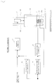
FIG. 1 is a block diagram depicting the structure of a control system for a production machine of a first embodiment of the present invention. -
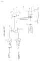
FIG. 2 is a block diagram depicting the structure of a control system for a production machine of a second embodiment of the present invention. -
FIG. 3 is a block diagram depicting the structure of a control system for a production machine of a third embodiment of the present invention. -
FIG. 4 is a block diagram depicting the structure of a control system for a production machine of a forth embodiment of the present invention. - Several embodiments that embody modes for carrying out the present invention are described below.
- A first embodiment of the present invention is described based on
FIG. 1 . - A production machine of the first embodiment is, for example, a component mount machine, a component assembling machine, or the like. In the case of a component mount machine, when a component is absorbed to an absorption nozzle to be mounted on a circuit board, an operation of lightly pressuring and mounting the component onto the circuit board by the absorption nozzle is controlled by a control system of the first embodiment. In the case of a component assembling machine, an operation of holding and press-fitting (inserting) a press-fit (insertion) component into a hole is controlled by a control system of the first embodiment.
- A
mobile body 11 of the production machine is slidably supported on ashaft 12, and is driven by anactuator 13. Theactuator 13 to drive themobile body 11 is configured of a motor such as a servo motor or step motor, a linear motor, etc. At a predetermined position in a moving direction of themobile body 11, apressure target 14 is placed. - A
piezoelectric element 15 is mounted on themobile body 11 at a position where an impact force is exerted when itstip part 11a collides with thepressure target 14. Thispiezoelectric element 15 functions as an impact-mitigating actuator for use in order to mitigate the impact force when thetip part 11a of themobile body 11 collides with thepressure target 14, and also functions as impact-force detecting means which detects an impact force when thetip part 11a of themobile body 11 collides with thepressure target 14. That is, by using the piezoelectric effect and the inverse piezoelectric effect, thepiezoelectric element 15 is used as a self-sensing actuator achieving both functions of an impact-mitigating actuator and impact-force detecting means. - A drive control system of the
actuator 13 is provided with a low-frequency-band signal extraction filter 16 (low-frequency-band signal extracting means) and a feedback control unit 17 (driving-force feedback control means), the low-frequency-bandsignal extraction filter 16 extracting a low-frequency-band signal component from an output signal of the piezoelectric element 15 (an impact-force detection signal) when thetip part 11a of themobile body 11 collides with thepressure target 14 and thefeedback control unit 17 performing feedback control over the driving force of the actuator 13 (a pressure force of themobile body 11 with respect to the pressure target 14) so that a difference between the low-frequency-band signal component extracted by this low-frequency-bandsignal extraction filter 16 and a pressure-force instruction is small. With the low-frequency-band signal component extracted by the low-frequency-bandsignal extraction filter 16 from the output signal of the piezoelectric element 15 (the impact-force detection signal), the magnitude of the impact force exerted on thetip part 11a of themobile body 11 is extracted, and feedback control is performed by thefeedback control unit 17 so that the driving force of the actuator 13 (the pressure force of themobile body 11 with respect to the pressure target 14) complies with the pressure-force instruction. - On the other hand, a drive control system of the
piezoelectric element 15 configuring an impact-mitigating actuator is provided with a high-frequency-band signal extraction filter 18 (high-frequency-band signal extracting means) and an impact-mitigating control unit 19 (impact-mitigating control means), the high-frequency-bandsignal extraction filter 18 extracting a high-frequency-band signal component from the output signal of the piezoelectric element 15 (an impact-force detection signal) when thetip part 11a of themobile body 11 collides with thepressure target 14 and the impact-mitigatingcontrol unit 19 controlling a drive voltage of the piezoelectric element 15 (a driving force of the impact-mitigating actuator) based on the high-frequency-band signal component extracted by the high-frequency-bandsignal extraction filter 18 so that the impact force when thetip part 11a of themobile body 11 collides with thepressure target 14 is mitigated. - The impact-mitigating
control unit 19 generates a drive signal having a waveform with a phase opposite to that of the high-frequency-band signal component extracted by the high-frequency-bandsignal extraction filter 18 and changes the drive voltage of thepiezoelectric element 15 with this drive signal, thereby changing the drive voltage of thepiezoelectric element 15 so that the impact force exerted on thetip part 11a of themobile body 11 is mitigated and mitigating the impact force exerted on thetip part 11a of themobile body 11. This impact-mitigatingcontrol unit 19 may be configured of a digital circuit. However, if digital processing cannot sufficiently follow the oscillation frequency of thepiezoelectric element 15 because the oscillation frequency is high, the impact-mitigatingcontrol unit 19 is preferably configured of an analog circuit. - In the first embodiment described above, with the low-frequency-band signal component extracted by the low-frequency-band
signal extraction filter 16 from the output signal of the piezoelectric element 15 (the impact-force detection signal) when thetip part 11a of themobile body 11 collides with thepressure target 14, the magnitude of the impact force exerted on thetip part 11a of themobile body 11 is extracted, and feedback control is performed by thefeedback control unit 17 so that the driving force of the actuator 13 (the pressure force of themobile body 11 with respect to the pressure target 14) complies with the pressure-force instruction. Also, based on the high-frequency-band signal component extracted by the high-frequency-bandsignal extraction filter 18 from the output signal of the piezoelectric element 15 (the impact-force detection signal), the drive voltage of the piezoelectric element 15 (the driving force of the impact-mitigating actuator) is controlled by the impact-mitigatingcontrol unit 19 so that the impact force when thetip part 11a of themobile body 11 collides with thepressure target 14 is mitigated. Therefore, the impact force when thetip part 11a of themobile body 11 collides with thepressure target 14 can be responsively mitigated, and the pressure force of themobile body 11 with respect to thepressure target 14 can be stabilized. - Furthermore, in the first embodiment, both functions of the impact-mitigating actuator and the impact-force detecting means are achieved by one
piezoelectric element 15. Therefore, the first embodiment has an advantage that low cost and space saving can be achieved. - In the first embodiment described above, the structure is such that both functions of the impact-mitigating actuator and the impact-force detecting means are achieved by one
piezoelectric element 15. In a second embodiment of the present invention depicted inFIG. 2 , thetip part 11a of themobile body 11 is provided with apiezoelectric element 21 and apiezoelectric element 22 in series in a direction of driving themobile body 11, thepiezoelectric element 21 for impact mitigation configuring an impact-mitigating actuator for use in order to mitigate an impact force when colliding with thepressure target 14 and thepiezoelectric element 22 for impact-force detection configuring impact-force detecting means which detects an impact force when colliding with thepressure target 14. At the instant when thepiezoelectric element 22 for impact-force detection detects a distortion due to a collision with thepressure target 14, the drive voltage of thepiezoelectric element 21 is controlled so that thepiezoelectric element 21 for impact mitigation is deformed in a direction opposite to a distortion direction. - To achieve this, a drive control system of the
piezoelectric element 21 for impact mitigation is preferably configured of the high-frequency-band signal extraction filter 18 (high-frequency-band signal extracting means) and the impact-mitigating control unit 19 (impact-mitigating control means), the high-frequency-bandsignal extraction filter 18 extracting a high-frequency-band signal component from an output signal of thepiezoelectric element 22 for impact-force detection (an impact-force detection signal) when thetip part 11a of themobile body 11 collides with thepressure target 14 and the impact-mitigatingcontrol unit 19 controlling a drive voltage of thepiezoelectric element 21 for impact mitigation based on the high-frequency-band signal component extracted by this high-frequency-bandsignal extraction filter 18 so that the impact force when thetip part 11a of themobile body 11 collides with thepressure target 14 is mitigated. Other points are similar to those in the first embodiment described above, and identical portions are provided with the same reference characters and their description is omitted. - In a third embodiment of the present invention depicted in
FIG. 3 , thetip part 11a of themobile body 11 is provided only with thepiezoelectric element 23 for impact-force detection configuring impact-force detecting means which detects an impact force when colliding with thepressure target 14. Apiezoelectric element 24 for impact mitigation configuring an impact-mitigating actuator for use in order to mitigate the impact force when thetip part 11a of themobile body 11 collides with thepressure target 14 is mounted on themobile body 11 so as to be positioned around thetip part 11a of themobile body 11, and acounter mass 25 is mounted on thispiezoelectric element 24 for impact mitigation. Thepiezoelectric element 24 for impact mitigation and thecounter mass 25 may be each formed in a ring shape, or a plurality of these may be provided. In short, any provision is possible so that the load of thecounter mass 25 equally acts on themobile body 11 with respect to the center line of themobile body 11. - In the third embodiment, at the instant when the
piezoelectric element 23 for impact-force detection detects a distortion due to a collision with thepressure target 14, the drive voltage of thepiezoelectric element 24 for impact mitigation is controlled so that thecounter mass 25 is moved in a direction of mitigating the impact force. - To achieve this, the drive control system of the
piezoelectric element 23 for impact mitigation is preferably configured of the high-frequency-band signal extraction filter 18 (high-frequency-band signal extracting means) and the impact-mitigating control unit 19 (impact-mitigating control means), the high-frequency-bandsignal extraction filter 18 extracting a high-frequency-band signal component from the output signal of thepiezoelectric element 23 for impact-force detection (an impact-force detection signal) when thetip part 11a of themobile body 11 collides with thepressure target 14 and the impact-mitigatingcontrol unit 19 controlling a drive voltage of thepiezoelectric element 24 for impact mitigation based on this high-frequency-band signal component extracted by the high-frequency-bandsignal extraction filter 18 so that the impact force when thetip part 11a of themobile body 11 collides with thepressure target 14 is mitigated. Other points are similar to those in the first embodiment described above, and identical portions are provided with the same reference characters and their description is omitted. - In a fourth embodiment of the present invention depicted in
FIG. 4 , the drive control system of theactuator 13 which drives themobile body 11 is provided with a position control unit 31 (position control means) which performs position control in which theactuator 13 is driven based on a position instruction to control the position of themobile body 11, a pressure-force control unit 32 (pressure-force control means) which performs pressure-force control in which theactuator 13 is controlled so that the pressure force of themobile body 11 with respect to thepressure target 14 complies with a pressure-force instruction, and a control-scheme switching unit 33 (control-scheme switching means) which switches a control scheme of theactuator 13 between position control by theposition control unit 31 and pressure-force control by the pressure-force control unit 32. - The
mobile body 11 is provided with apiezoelectric element 34 for collision detection configuring a collision detecting means which detects that thetip part 11a collides with thepressure target 14, and an output signal of thispiezoelectric element 34 is inputted to acollision detecting unit 35. At the instant when thetip part 11a of themobile body 11 collides with thepressure target 14 to change the output signal of thepiezoelectric element 34, a collision detection signal is outputted from thecollision detecting unit 35 to the control-scheme switching unit 33. Before a collision detection signal is outputted from the collision detecting unit 35 (before a collision is detected), the control-scheme switching unit 33 is switched to and kept in the state in which a position control signal of theposition control unit 31 is outputted to theactuator 13, and theactuator 13 is driven so that the position of themobile body 11 complies with the position instruction. At the instant when a collision detection signal is outputted from the collision detecting unit 35 (at the instant when a collision is detected), the state is switched to the state in which the control-scheme switching unit 33 outputs a pressure-force control signal of the pressure-force control unit 32 to theactuator 13, and theactuator 13 is driven so that the pressure force of themobile body 11 with respect to thepressure target 14 complies with the pressure-force instruction. - According to the fourth embodiment described above, at the instant when the
tip part 11a of themobile body 11 collides with thepressure target 14 by position control, switching can be made from position control to pressure-force control. Therefore, while the driving speed of themobile body 11 is increased by position control, the impact force is effectively mitigated by pressure-force control after collision, and thereby the pressure force of themobile body 11 with respect to thepressure target 14 can be stabilized. - Note that the fourth embodiment described above may be implemented in combination with any of the first to third embodiments described above.
- In addition, it is needless to say that the present invention can be implemented with various changes within a range not deviating from the gist of the present invention. For example, the present invention may be implemented by changing the structure of the
mobile body 11 and the like as appropriate. -
- 11 mobile body
- 13 actuator
- 14 pressure target
- 15 piezoelectric element (impact-mitigating actuator, impact-force detecting means)
- 16 low-frequency-band signal extraction filter (low-frequency-band signal extracting means)
- 17 feedback control unit (driving-force feedback control means)
- 18 high-frequency-band signal extraction filter (high-frequency-band signal extracting means)
- 19 impact-mitigating control unit (impact-mitigating control means)
- 21 piezoelectric element for impact mitigation (impact-mitigating actuator)
- 22 piezoelectric element for impact-force detection (impact-force detecting means)
- 23 piezoelectric element for impact-force detection (impact-force detecting means)
- 24 piezoelectric element for impact mitigation (impact-mitigating actuator)
- 25 counter mass
- 31 position control unit (position control means)
- 32 pressure-force control unit (pressure-force control means)
- 33 control-scheme switching unit (control-scheme switching means)
- 34 piezoelectric element for collision detection (collision detecting means)
- 35 collision detecting unit
Claims (5)
- A production machine including a function of moving a mobile body by an actuator until the mobile body collides with a pressure target and controlling a pressure force of the mobile body with respect to the pressure target, the production machine comprising:an impact-mitigating actuator for use in order to mitigate an impact force when the mobile body collides with the pressure target;impact-force detecting means which detects the impact force when the mobile body collides with the pressure target;low-frequency-band signal extracting means which extracts a low-frequency-band signal component from an output signal of the impact-force detecting means;driving-force feedback control means which controls a driving force of the main actuator so that a difference between the low-frequency-band signal component extracted by the low-frequency signal extracting means and a pressure-force instruction is small;high-frequency-band signal extracting means which extracts a high-frequency-band signal component from the output signal of the impact-force detecting means; andimpact-mitigating control means which controls a driving force of the impact-mitigating actuator based on the high-frequency-band signal component extracted by the high-frequency signal extracting means so that the impact force when the mobile body collides with the pressure target is mitigated.
- The production machine according to claim 1, wherein
the impact-mitigating actuator and the impact-force detecting means are configured of one piezoelectric element. - A production machine including a function of moving a mobile body by an actuator until the mobile body collides with a pressure target and controlling a pressure force of the mobile body with respect to the pressure target, the production machine comprising:an impact-mitigating actuator for use in order to mitigate an impact force when the mobile body collides with the pressure target;impact-force detecting means which detects the impact force when the mobile body collides with the pressure target; andimpact-mitigating control means which controls a driving force of the impact-mitigating actuator so that the impact force when the mobile body collides with the pressure target is mitigated, whereinthe impact-mitigating actuator and the impact-force detecting means are configured of separate piezoelectric elements and are provided in series in a direction of driving the mobile body, andat the instant when the piezoelectric element configuring the impact-force detecting means detects a distortion due to a collision with the pressure target, the impact-mitigating control means controls a drive voltage of the piezoelectric element configuring the impact-mitigating actuator so that the piezoelectric element is deformed in a direction opposite to a direction of the distortion.
- A production machine including a function of moving a mobile body by an actuator until the mobile body collides with a pressure target and controlling a pressure force of the mobile body with respect to the pressure target, the production machine comprising:an impact-mitigating actuator for use in order to mitigate an impact force when the mobile body collides with the pressure target;impact-force detecting means which detects the impact force when the mobile body collides with the pressure target; andimpact-mitigating control means which controls a driving force of the impact-mitigating actuator so that the impact force when the mobile body collides with the pressure target is mitigated, whereinthe impact-mitigating actuator and the impact-force detecting means are configured of separate piezoelectric elements, and a counter mass is mounted on the piezoelectric element configuring the impact-mitigating actuator, andat the instant when the piezoelectric element configuring the impact-force detecting means detects a distortion due to a collision with the pressure target, the impact-mitigating control means controls a drive voltage of the piezoelectric element configuring the impact-mitigating actuator so that the counter mass moves in a direction of mitigating the impact force.
- A production machine including a function of moving a mobile body by an actuator until the mobile body collides with a pressure target and controlling a pressure force of the mobile body with respect to the pressure target, the production machine comprising:position control means which performs position control of driving the actuator based on a position instruction and controlling a position of the mobile body;pressure-force control means which performs pressure-force control of controlling the actuator so that the pressure force of the mobile body with respect to the pressure target complies with a pressure-force instruction;collision detecting means which detects that the mobile body collides with the pressure target; andcontrol-scheme switching means which causes position control to be performed by the position control means before a collision of the mobile body is detected by the collision detecting means, and causes pressure-force control to be performed by the driving-force control means after a collision of the mobile body is detected by the collision detecting means.
Applications Claiming Priority (2)
| Application Number | Priority Date | Filing Date | Title |
|---|---|---|---|
| JP2011152673A JP5725657B2 (en) | 2011-07-11 | 2011-07-11 | Production machine |
| PCT/JP2012/061261 WO2013008518A1 (en) | 2011-07-11 | 2012-04-26 | Manufacturing machine |
Publications (3)
| Publication Number | Publication Date |
|---|---|
| EP2734023A1 true EP2734023A1 (en) | 2014-05-21 |
| EP2734023A4 EP2734023A4 (en) | 2015-05-13 |
| EP2734023B1 EP2734023B1 (en) | 2019-06-26 |
Family
ID=47505817
Family Applications (1)
| Application Number | Title | Priority Date | Filing Date |
|---|---|---|---|
| EP12811792.6A Active EP2734023B1 (en) | 2011-07-11 | 2012-04-26 | Manufacturing machine |
Country Status (4)
| Country | Link |
|---|---|
| EP (1) | EP2734023B1 (en) |
| JP (1) | JP5725657B2 (en) |
| CN (1) | CN103703877B (en) |
| WO (1) | WO2013008518A1 (en) |
Families Citing this family (1)
| Publication number | Priority date | Publication date | Assignee | Title |
|---|---|---|---|---|
| JP6666651B2 (en) * | 2014-10-27 | 2020-03-18 | ハンファ精密機械株式会社 | Component mounting head of surface mounter |
Family Cites Families (11)
| Publication number | Priority date | Publication date | Assignee | Title |
|---|---|---|---|---|
| JPH0555797A (en) * | 1991-08-29 | 1993-03-05 | Hitachi Ltd | Head device for mounting electronic components |
| JPH07249896A (en) | 1994-01-21 | 1995-09-26 | Yamaha Motor Co Ltd | Nozzle drive device for mounting machine |
| JP4100741B2 (en) * | 1997-11-06 | 2008-06-11 | 松下電器産業株式会社 | Component mounting apparatus and method |
| DE19954310B4 (en) * | 1999-11-11 | 2007-01-18 | Thoms, Volker, Prof.Dr. | Method for rapid control of drawing operations in presses and suitable drawing press for this purpose |
| JP3851854B2 (en) * | 2002-08-30 | 2006-11-29 | 山形カシオ株式会社 | Electronic component mounting device |
| JP2004338067A (en) | 2003-05-19 | 2004-12-02 | Okuma Corp | Pallet changer |
| JP2006212644A (en) * | 2005-02-01 | 2006-08-17 | Fanuc Ltd | Die cushion controller |
| DE102005012876A1 (en) * | 2005-03-19 | 2006-09-21 | Müller Weingarten AG | Method and device for controlling and regulating servo-electric drawing cushions |
| JP4041508B2 (en) * | 2005-07-11 | 2008-01-30 | ファナック株式会社 | Servo die cushion control device |
| JP5043793B2 (en) * | 2008-09-30 | 2012-10-10 | アズビル株式会社 | Automatic mounting device |
| CN201750672U (en) * | 2010-04-08 | 2011-02-16 | 东莞市新泽谷机械有限公司 | Vertical plug-in machine |
-
2011
- 2011-07-11 JP JP2011152673A patent/JP5725657B2/en active Active
-
2012
- 2012-04-26 WO PCT/JP2012/061261 patent/WO2013008518A1/en not_active Ceased
- 2012-04-26 CN CN201280034453.5A patent/CN103703877B/en active Active
- 2012-04-26 EP EP12811792.6A patent/EP2734023B1/en active Active
Also Published As
| Publication number | Publication date |
|---|---|
| JP5725657B2 (en) | 2015-05-27 |
| JP2013021103A (en) | 2013-01-31 |
| EP2734023A4 (en) | 2015-05-13 |
| CN103703877A (en) | 2014-04-02 |
| EP2734023B1 (en) | 2019-06-26 |
| WO2013008518A1 (en) | 2013-01-17 |
| CN103703877B (en) | 2016-04-13 |
Similar Documents
| Publication | Publication Date | Title |
|---|---|---|
| US7859352B2 (en) | Systems and methods to overcome DC offsets in amplifiers used to start resonant micro-electro mechanical systems | |
| CN103140698B (en) | The controlling method of active damper, vehicle, active damper | |
| WO2006096288A3 (en) | Skipping frequencies for variable speed controls | |
| WO2009078074A1 (en) | Electric power-steering controller | |
| US9955269B2 (en) | Microphone system with driven electrodes | |
| US8763771B2 (en) | Active oscillation damper without direct acceleration detection | |
| JP5917294B2 (en) | Motor drive circuit | |
| JP6254707B2 (en) | Vibration reduction device using magnet | |
| EP2734023B1 (en) | Manufacturing machine | |
| US20140117801A1 (en) | Active magnetic bearing comprising means for damping the radial motion of a shaft of a rotary machine | |
| WO2012120149A3 (en) | Driving device having an actively supported drive shaft | |
| JP2012125062A (en) | Motor control circuit | |
| KR101588771B1 (en) | Valve driving device using piezoelectric actuator | |
| JP2013212564A (en) | Control device, control method, and robot | |
| US20100301796A1 (en) | Reciprocating actuator with closed loop servocontrol | |
| KR102276198B1 (en) | Method and apparatus for controlling persistent oscillation of servo systems | |
| US20140306625A1 (en) | Driving circuit for vibration motor and driving method for vibration motor | |
| KR20150031702A (en) | Actuator of rear wheel type steering apparatus for vehicle | |
| JP7106052B2 (en) | Driving device, driving method and operating device for vibration actuator | |
| US20190260323A1 (en) | Linear vibration motor | |
| KR102458478B1 (en) | Air control device for mounter | |
| CN107489569B (en) | A kind of method, oil pump and engine reducing oil pump noise | |
| US10471529B2 (en) | Electrical discharge machining device and method for the same | |
| KR102338128B1 (en) | Apparatus for suppressing vibration of compressor piping, system for suppressing vibration of compressor piping and method for suppressing vibration of compressor piping | |
| WO2016028501A1 (en) | Exhaust-gas turbocharger |
Legal Events
| Date | Code | Title | Description |
|---|---|---|---|
| PUAI | Public reference made under article 153(3) epc to a published international application that has entered the european phase |
Free format text: ORIGINAL CODE: 0009012 |
|
| 17P | Request for examination filed |
Effective date: 20140109 |
|
| AK | Designated contracting states |
Kind code of ref document: A1 Designated state(s): AL AT BE BG CH CY CZ DE DK EE ES FI FR GB GR HR HU IE IS IT LI LT LU LV MC MK MT NL NO PL PT RO RS SE SI SK SM TR |
|
| DAX | Request for extension of the european patent (deleted) | ||
| RA4 | Supplementary search report drawn up and despatched (corrected) |
Effective date: 20150415 |
|
| RIC1 | Information provided on ipc code assigned before grant |
Ipc: B23P 19/02 20060101ALI20150409BHEP Ipc: G05B 19/19 20060101ALI20150409BHEP Ipc: H05K 13/04 20060101AFI20150409BHEP |
|
| RAP1 | Party data changed (applicant data changed or rights of an application transferred) |
Owner name: FUJI CORPORATION |
|
| GRAP | Despatch of communication of intention to grant a patent |
Free format text: ORIGINAL CODE: EPIDOSNIGR1 |
|
| STAA | Information on the status of an ep patent application or granted ep patent |
Free format text: STATUS: GRANT OF PATENT IS INTENDED |
|
| RIN1 | Information on inventor provided before grant (corrected) |
Inventor name: NAGIRI, KEISUKE Inventor name: FUJITA, MASATOSHI Inventor name: NAGATA, RYO |
|
| RIC1 | Information provided on ipc code assigned before grant |
Ipc: G01L 5/00 20060101ALI20190122BHEP Ipc: G05B 19/19 20060101ALI20190122BHEP Ipc: H05K 13/04 20060101AFI20190122BHEP Ipc: B23P 19/02 20060101ALI20190122BHEP |
|
| INTG | Intention to grant announced |
Effective date: 20190213 |
|
| GRAS | Grant fee paid |
Free format text: ORIGINAL CODE: EPIDOSNIGR3 |
|
| GRAA | (expected) grant |
Free format text: ORIGINAL CODE: 0009210 |
|
| STAA | Information on the status of an ep patent application or granted ep patent |
Free format text: STATUS: THE PATENT HAS BEEN GRANTED |
|
| AK | Designated contracting states |
Kind code of ref document: B1 Designated state(s): AL AT BE BG CH CY CZ DE DK EE ES FI FR GB GR HR HU IE IS IT LI LT LU LV MC MK MT NL NO PL PT RO RS SE SI SK SM TR |
|
| REG | Reference to a national code |
Ref country code: GB Ref legal event code: FG4D |
|
| REG | Reference to a national code |
Ref country code: CH Ref legal event code: EP |
|
| REG | Reference to a national code |
Ref country code: AT Ref legal event code: REF Ref document number: 1149845 Country of ref document: AT Kind code of ref document: T Effective date: 20190715 |
|
| REG | Reference to a national code |
Ref country code: DE Ref legal event code: R096 Ref document number: 602012061491 Country of ref document: DE |
|
| REG | Reference to a national code |
Ref country code: IE Ref legal event code: FG4D |
|
| REG | Reference to a national code |
Ref country code: NL Ref legal event code: MP Effective date: 20190626 |
|
| PG25 | Lapsed in a contracting state [announced via postgrant information from national office to epo] |
Ref country code: LT Free format text: LAPSE BECAUSE OF FAILURE TO SUBMIT A TRANSLATION OF THE DESCRIPTION OR TO PAY THE FEE WITHIN THE PRESCRIBED TIME-LIMIT Effective date: 20190626 Ref country code: HR Free format text: LAPSE BECAUSE OF FAILURE TO SUBMIT A TRANSLATION OF THE DESCRIPTION OR TO PAY THE FEE WITHIN THE PRESCRIBED TIME-LIMIT Effective date: 20190626 Ref country code: FI Free format text: LAPSE BECAUSE OF FAILURE TO SUBMIT A TRANSLATION OF THE DESCRIPTION OR TO PAY THE FEE WITHIN THE PRESCRIBED TIME-LIMIT Effective date: 20190626 Ref country code: AL Free format text: LAPSE BECAUSE OF FAILURE TO SUBMIT A TRANSLATION OF THE DESCRIPTION OR TO PAY THE FEE WITHIN THE PRESCRIBED TIME-LIMIT Effective date: 20190626 Ref country code: SE Free format text: LAPSE BECAUSE OF FAILURE TO SUBMIT A TRANSLATION OF THE DESCRIPTION OR TO PAY THE FEE WITHIN THE PRESCRIBED TIME-LIMIT Effective date: 20190626 Ref country code: NO Free format text: LAPSE BECAUSE OF FAILURE TO SUBMIT A TRANSLATION OF THE DESCRIPTION OR TO PAY THE FEE WITHIN THE PRESCRIBED TIME-LIMIT Effective date: 20190926 |
|
| REG | Reference to a national code |
Ref country code: LT Ref legal event code: MG4D |
|
| PG25 | Lapsed in a contracting state [announced via postgrant information from national office to epo] |
Ref country code: GR Free format text: LAPSE BECAUSE OF FAILURE TO SUBMIT A TRANSLATION OF THE DESCRIPTION OR TO PAY THE FEE WITHIN THE PRESCRIBED TIME-LIMIT Effective date: 20190927 Ref country code: LV Free format text: LAPSE BECAUSE OF FAILURE TO SUBMIT A TRANSLATION OF THE DESCRIPTION OR TO PAY THE FEE WITHIN THE PRESCRIBED TIME-LIMIT Effective date: 20190626 Ref country code: RS Free format text: LAPSE BECAUSE OF FAILURE TO SUBMIT A TRANSLATION OF THE DESCRIPTION OR TO PAY THE FEE WITHIN THE PRESCRIBED TIME-LIMIT Effective date: 20190626 Ref country code: BG Free format text: LAPSE BECAUSE OF FAILURE TO SUBMIT A TRANSLATION OF THE DESCRIPTION OR TO PAY THE FEE WITHIN THE PRESCRIBED TIME-LIMIT Effective date: 20190926 |
|
| REG | Reference to a national code |
Ref country code: AT Ref legal event code: MK05 Ref document number: 1149845 Country of ref document: AT Kind code of ref document: T Effective date: 20190626 |
|
| PG25 | Lapsed in a contracting state [announced via postgrant information from national office to epo] |
Ref country code: SK Free format text: LAPSE BECAUSE OF FAILURE TO SUBMIT A TRANSLATION OF THE DESCRIPTION OR TO PAY THE FEE WITHIN THE PRESCRIBED TIME-LIMIT Effective date: 20190626 Ref country code: EE Free format text: LAPSE BECAUSE OF FAILURE TO SUBMIT A TRANSLATION OF THE DESCRIPTION OR TO PAY THE FEE WITHIN THE PRESCRIBED TIME-LIMIT Effective date: 20190626 Ref country code: NL Free format text: LAPSE BECAUSE OF FAILURE TO SUBMIT A TRANSLATION OF THE DESCRIPTION OR TO PAY THE FEE WITHIN THE PRESCRIBED TIME-LIMIT Effective date: 20190626 Ref country code: CZ Free format text: LAPSE BECAUSE OF FAILURE TO SUBMIT A TRANSLATION OF THE DESCRIPTION OR TO PAY THE FEE WITHIN THE PRESCRIBED TIME-LIMIT Effective date: 20190626 Ref country code: RO Free format text: LAPSE BECAUSE OF FAILURE TO SUBMIT A TRANSLATION OF THE DESCRIPTION OR TO PAY THE FEE WITHIN THE PRESCRIBED TIME-LIMIT Effective date: 20190626 Ref country code: PT Free format text: LAPSE BECAUSE OF FAILURE TO SUBMIT A TRANSLATION OF THE DESCRIPTION OR TO PAY THE FEE WITHIN THE PRESCRIBED TIME-LIMIT Effective date: 20191028 Ref country code: AT Free format text: LAPSE BECAUSE OF FAILURE TO SUBMIT A TRANSLATION OF THE DESCRIPTION OR TO PAY THE FEE WITHIN THE PRESCRIBED TIME-LIMIT Effective date: 20190626 |
|
| PG25 | Lapsed in a contracting state [announced via postgrant information from national office to epo] |
Ref country code: SM Free format text: LAPSE BECAUSE OF FAILURE TO SUBMIT A TRANSLATION OF THE DESCRIPTION OR TO PAY THE FEE WITHIN THE PRESCRIBED TIME-LIMIT Effective date: 20190626 Ref country code: IS Free format text: LAPSE BECAUSE OF FAILURE TO SUBMIT A TRANSLATION OF THE DESCRIPTION OR TO PAY THE FEE WITHIN THE PRESCRIBED TIME-LIMIT Effective date: 20191026 Ref country code: IT Free format text: LAPSE BECAUSE OF FAILURE TO SUBMIT A TRANSLATION OF THE DESCRIPTION OR TO PAY THE FEE WITHIN THE PRESCRIBED TIME-LIMIT Effective date: 20190626 Ref country code: ES Free format text: LAPSE BECAUSE OF FAILURE TO SUBMIT A TRANSLATION OF THE DESCRIPTION OR TO PAY THE FEE WITHIN THE PRESCRIBED TIME-LIMIT Effective date: 20190626 |
|
| PG25 | Lapsed in a contracting state [announced via postgrant information from national office to epo] |
Ref country code: TR Free format text: LAPSE BECAUSE OF FAILURE TO SUBMIT A TRANSLATION OF THE DESCRIPTION OR TO PAY THE FEE WITHIN THE PRESCRIBED TIME-LIMIT Effective date: 20190626 |
|
| PG25 | Lapsed in a contracting state [announced via postgrant information from national office to epo] |
Ref country code: PL Free format text: LAPSE BECAUSE OF FAILURE TO SUBMIT A TRANSLATION OF THE DESCRIPTION OR TO PAY THE FEE WITHIN THE PRESCRIBED TIME-LIMIT Effective date: 20190626 Ref country code: DK Free format text: LAPSE BECAUSE OF FAILURE TO SUBMIT A TRANSLATION OF THE DESCRIPTION OR TO PAY THE FEE WITHIN THE PRESCRIBED TIME-LIMIT Effective date: 20190626 |
|
| PG25 | Lapsed in a contracting state [announced via postgrant information from national office to epo] |
Ref country code: IS Free format text: LAPSE BECAUSE OF FAILURE TO SUBMIT A TRANSLATION OF THE DESCRIPTION OR TO PAY THE FEE WITHIN THE PRESCRIBED TIME-LIMIT Effective date: 20200224 |
|
| REG | Reference to a national code |
Ref country code: DE Ref legal event code: R097 Ref document number: 602012061491 Country of ref document: DE |
|
| PLBE | No opposition filed within time limit |
Free format text: ORIGINAL CODE: 0009261 |
|
| STAA | Information on the status of an ep patent application or granted ep patent |
Free format text: STATUS: NO OPPOSITION FILED WITHIN TIME LIMIT |
|
| PG2D | Information on lapse in contracting state deleted |
Ref country code: IS |
|
| 26N | No opposition filed |
Effective date: 20200603 |
|
| PG25 | Lapsed in a contracting state [announced via postgrant information from national office to epo] |
Ref country code: SI Free format text: LAPSE BECAUSE OF FAILURE TO SUBMIT A TRANSLATION OF THE DESCRIPTION OR TO PAY THE FEE WITHIN THE PRESCRIBED TIME-LIMIT Effective date: 20190626 |
|
| PG25 | Lapsed in a contracting state [announced via postgrant information from national office to epo] |
Ref country code: MC Free format text: LAPSE BECAUSE OF FAILURE TO SUBMIT A TRANSLATION OF THE DESCRIPTION OR TO PAY THE FEE WITHIN THE PRESCRIBED TIME-LIMIT Effective date: 20190626 |
|
| PG25 | Lapsed in a contracting state [announced via postgrant information from national office to epo] |
Ref country code: LU Free format text: LAPSE BECAUSE OF NON-PAYMENT OF DUE FEES Effective date: 20200426 Ref country code: FR Free format text: LAPSE BECAUSE OF NON-PAYMENT OF DUE FEES Effective date: 20200430 |
|
| REG | Reference to a national code |
Ref country code: BE Ref legal event code: MM Effective date: 20200430 |
|
| PG25 | Lapsed in a contracting state [announced via postgrant information from national office to epo] |
Ref country code: BE Free format text: LAPSE BECAUSE OF NON-PAYMENT OF DUE FEES Effective date: 20200430 |
|
| GBPC | Gb: european patent ceased through non-payment of renewal fee |
Effective date: 20200426 |
|
| PG25 | Lapsed in a contracting state [announced via postgrant information from national office to epo] |
Ref country code: IE Free format text: LAPSE BECAUSE OF NON-PAYMENT OF DUE FEES Effective date: 20200426 Ref country code: GB Free format text: LAPSE BECAUSE OF NON-PAYMENT OF DUE FEES Effective date: 20200426 |
|
| PG25 | Lapsed in a contracting state [announced via postgrant information from national office to epo] |
Ref country code: MT Free format text: LAPSE BECAUSE OF FAILURE TO SUBMIT A TRANSLATION OF THE DESCRIPTION OR TO PAY THE FEE WITHIN THE PRESCRIBED TIME-LIMIT Effective date: 20190626 Ref country code: CY Free format text: LAPSE BECAUSE OF FAILURE TO SUBMIT A TRANSLATION OF THE DESCRIPTION OR TO PAY THE FEE WITHIN THE PRESCRIBED TIME-LIMIT Effective date: 20190626 |
|
| PG25 | Lapsed in a contracting state [announced via postgrant information from national office to epo] |
Ref country code: MK Free format text: LAPSE BECAUSE OF FAILURE TO SUBMIT A TRANSLATION OF THE DESCRIPTION OR TO PAY THE FEE WITHIN THE PRESCRIBED TIME-LIMIT Effective date: 20190626 |
|
| P01 | Opt-out of the competence of the unified patent court (upc) registered |
Effective date: 20230328 |
|
| PGFP | Annual fee paid to national office [announced via postgrant information from national office to epo] |
Ref country code: DE Payment date: 20250305 Year of fee payment: 14 |
|
| PGFP | Annual fee paid to national office [announced via postgrant information from national office to epo] |
Ref country code: CH Payment date: 20250501 Year of fee payment: 14 |
|
| REG | Reference to a national code |
Ref country code: CH Ref legal event code: U11 Free format text: ST27 STATUS EVENT CODE: U-0-0-U10-U11 (AS PROVIDED BY THE NATIONAL OFFICE) Effective date: 20260501 |