EP2734016A1 - Drift tube manufacturing method and drift tube - Google Patents
Drift tube manufacturing method and drift tube Download PDFInfo
- Publication number
- EP2734016A1 EP2734016A1 EP13188266.4A EP13188266A EP2734016A1 EP 2734016 A1 EP2734016 A1 EP 2734016A1 EP 13188266 A EP13188266 A EP 13188266A EP 2734016 A1 EP2734016 A1 EP 2734016A1
- Authority
- EP
- European Patent Office
- Prior art keywords
- housing
- magnet
- lid
- hole
- drift tube
- Prior art date
- Legal status (The legal status is an assumption and is not a legal conclusion. Google has not performed a legal analysis and makes no representation as to the accuracy of the status listed.)
- Granted
Links
Images



Classifications
-
- H—ELECTRICITY
- H05—ELECTRIC TECHNIQUES NOT OTHERWISE PROVIDED FOR
- H05H—PLASMA TECHNIQUE; PRODUCTION OF ACCELERATED ELECTRICALLY-CHARGED PARTICLES OR OF NEUTRONS; PRODUCTION OR ACCELERATION OF NEUTRAL MOLECULAR OR ATOMIC BEAMS
- H05H7/00—Details of devices of the types covered by groups H05H9/00, H05H11/00, H05H13/00
- H05H7/22—Details of linear accelerators, e.g. drift tubes
-
- H—ELECTRICITY
- H05—ELECTRIC TECHNIQUES NOT OTHERWISE PROVIDED FOR
- H05H—PLASMA TECHNIQUE; PRODUCTION OF ACCELERATED ELECTRICALLY-CHARGED PARTICLES OR OF NEUTRONS; PRODUCTION OR ACCELERATION OF NEUTRAL MOLECULAR OR ATOMIC BEAMS
- H05H9/00—Linear accelerators
- H05H9/04—Standing-wave linear accelerators
- H05H9/041—Hadron LINACS
- H05H9/042—Drift tube LINACS
-
- B—PERFORMING OPERATIONS; TRANSPORTING
- B23—MACHINE TOOLS; METAL-WORKING NOT OTHERWISE PROVIDED FOR
- B23K—SOLDERING OR UNSOLDERING; WELDING; CLADDING OR PLATING BY SOLDERING OR WELDING; CUTTING BY APPLYING HEAT LOCALLY, e.g. FLAME CUTTING; WORKING BY LASER BEAM
- B23K26/00—Working by laser beam, e.g. welding, cutting or boring
- B23K26/20—Bonding
- B23K26/32—Bonding taking account of the properties of the material involved
-
- B—PERFORMING OPERATIONS; TRANSPORTING
- B23—MACHINE TOOLS; METAL-WORKING NOT OTHERWISE PROVIDED FOR
- B23K—SOLDERING OR UNSOLDERING; WELDING; CLADDING OR PLATING BY SOLDERING OR WELDING; CUTTING BY APPLYING HEAT LOCALLY, e.g. FLAME CUTTING; WORKING BY LASER BEAM
- B23K2103/00—Materials to be soldered, welded or cut
- B23K2103/02—Iron or ferrous alloys
- B23K2103/04—Steel or steel alloys
- B23K2103/05—Stainless steel
-
- B—PERFORMING OPERATIONS; TRANSPORTING
- B23—MACHINE TOOLS; METAL-WORKING NOT OTHERWISE PROVIDED FOR
- B23K—SOLDERING OR UNSOLDERING; WELDING; CLADDING OR PLATING BY SOLDERING OR WELDING; CUTTING BY APPLYING HEAT LOCALLY, e.g. FLAME CUTTING; WORKING BY LASER BEAM
- B23K2103/00—Materials to be soldered, welded or cut
- B23K2103/08—Non-ferrous metals or alloys
- B23K2103/12—Copper or alloys thereof
-
- H—ELECTRICITY
- H05—ELECTRIC TECHNIQUES NOT OTHERWISE PROVIDED FOR
- H05H—PLASMA TECHNIQUE; PRODUCTION OF ACCELERATED ELECTRICALLY-CHARGED PARTICLES OR OF NEUTRONS; PRODUCTION OR ACCELERATION OF NEUTRAL MOLECULAR OR ATOMIC BEAMS
- H05H7/00—Details of devices of the types covered by groups H05H9/00, H05H11/00, H05H13/00
- H05H7/22—Details of linear accelerators, e.g. drift tubes
- H05H2007/222—Details of linear accelerators, e.g. drift tubes drift tubes
Definitions
- the present invention relates to a manufacturing method of a drift tube which is used for a drift-tube-type accelerator, and to the drift tube.
- a drift-tube-type accelerator is provided with, inside a cylindrical tube, a plurality of drift tubes disposed at intervals on and along the central axis of the tube (e.g., see Patent Literature 1).
- Each drift tube has an annular shape with a through-hole formed at the center part, and magnets for generating magnetic fields are embedded on the outer circumferential side of the through-hole.
- This drift tube is suspended by a rod-like stem from the upper side of the tube so that the through-hole is positioned on the central axis of the tube.
- a particle beam such as a proton beam and an ion beam generated by a beam generator is accelerated inside the tube and fired at a target to thereby carry out experiments and the like.
- the particle beam is directed through the through-hole of the drift tube so that the particle beam is focused by the magnetic fields generated by the magnets.
- the permanent magnet is housed in a housing of the drift tube from an opening part formed in the housing, the opening part of the housing is covered by a lid, and the lid and the housing are welded together.
- electron beam welding is used for the welding. That is, since electron beam welding is performed under vacuum, heat cannot be released and thermal effect increases, leading to demagnetization of the permanent magnet.
- the housing is formed of a material having low thermal conductivity, such as stainless alloy, the cooling efficiency is poor relative to an amount of heat which is generated on a surface of the drift tube by the particle beam during operation of the accelerator. Then, there is a problem that temperature rise becomes larger, causing thermal strain of the housing or the lid and demagnetization of the permanent magnet.
- the present invention has been made in view of the above situation, and an object thereof is to provide a drift tube manufacturing method and a drift tube which can reduce the cost while securing an adequate level of particle beam focusing performance.
- a manufacturing method of a drift tube installed in a drift-tube-type accelerator including: a magnet housing stage of housing a predetermined number of permanent magnets in a housing, which has a through-hole at a center part and an annular magnet housing space on an outer circumferential side of the through-hole, from an opening part of the magnet housing space into the magnet housing space; and a welding stage of setting a lid for covering the opening part on the opening part, and welding the lid and the housing by laser beam welding, in which at least a surface of the housing and a surface of the lid are formed of copper.
- a large number of the drift tubes as described above are arrayed, inside a cylindrical tube constituting the accelerator, along the central axis of the tube.
- the permanent magnet as the magnet which generates magnetic fields for focusing the particle beam
- the structure of the drift tube can be made simpler compared to a case where the electromagnet is used as the magnet.
- the permanent magnet is little affected by heat from welding, and performance degradation of the permanent magnet can be prevented.
- the housing and the lid by forming the housing and the lid with copper which has high thermal conductivity, efficiency during cooling is higher and the temperature is less likely to increase compared to a case where the housing and the lid are formed of stainless alloy which has low thermal conductivity.
- the temperature rise becomes smaller relative to the amount of heat which is generated on the housing by the particle beam during operation of the accelerator, thermal strain of the housing or the lid and performance degradation of the permanent magnet can be suppressed.
- the housing and the lid it is only necessary that at least the surface of the housing and the surface of the lid (more specifically, e.g., at least a surface of a portion to be welded between the housing and the lid) are formed of copper.
- the housing and the lid themselves may be formed of stainless alloy, or the like, and the entire surfaces may be formed of copper using a method such as electroforming.
- the housing and the lid themselves may be formed of copper.
- the housing has an opening part at one end side of the through-hole, and in the welding stage, at least an inner circumferential portion of the lid and a portion around the through-hole of the housing may be welded by laser beam welding. That is, only the portion around the through-hole at the center part of the housing is welded by laser beam welding, and other portions, namely, a welding portion between the outer circumferential portion of the lid and the portion of the housing on the outer circumferential side of the opening part may be welded by another welding method such as electron beam welding. Since the magnetic fields of the magnets are concentrated in the center part of the housing, adverse effect of using electron beam welding is large. Therefore, using laser beam welding here is especially advantageous, although in terms of work efficiency, it is preferable to weld the lid and the housing by laser beam welding only.
- the predetermined number of permanent magnets may be housed in a magnet case, and the magnet case may be housed in the magnet housing space. This allows the permanent magnets to be set in the magnet housing space with high accuracy. Accordingly, a center of a magnetic field, etc. of the permanent magnet can be positioned with high accuracy. In addition, assembly of the drift tube becomes easier.
- a drift tube installed in a drift-tube-type accelerator, including: a housing which has a through-hole at a center part and is formed with an annular magnet housing space, which has an opening part on one end side of the through-hole, on an outer circumferential side of the through-hole; a predetermined number of permanent magnets housed in the magnet housing space; and a lid which covers the opening part and is welded to the housing, in which at least a surface of the housing and a surface of the lid are formed of copper.
- a drift tube can be formed by the drift tube manufacturing method described above.
- a drift-tube-type accelerator 10 is provided with, inside a cylindrical tube 11, a plurality of drift tubes 20 disposed at intervals on and along a central axis C of the tube 11.
- the tube 11 is installed on the floor through legs 15.
- each drift tube 20 has an annular shape including: disc-shaped end surface parts 20a and 20b formed parallel to each other with a clearance therebetween; a substantially cylindrical outer circumferential surface part 20c formed between outer circumferential portions of the end surface parts 20a and 20b; and a through-hole 21 communicating between center parts of the end surface parts 20a and 20b.
- this drift tube 20 is suspended by a rod-like stem 23 from an upper side of the tube 11 so that the center of the through-hole 21 is positioned on the central axis C of the tube 11.
- the drift tube 20 is provided with: a housing 24 having a magnet housing space 24s; a magnet case 25 housed in the magnet housing space 24s; magnets (permanent magnets) 22 which are held by the magnet case 25 on the outer circumferential side of the through-hole 21 and generate a magnetic field; and a lid 27 which forms the end surface part 20b and covers the opening part 24k of the magnet housing space 24s.
- the housing 24 is formed to include: a cylindrical wall part 24a forming the through-hole 21; a disc part 24b extending from one end of the cylindrical wall part 24a toward the outer circumferential side and forming the end surface part 20a; and an outer circumferential wall part 24c extending from an outer circumferential portion of the disc part 24b, perpendicularly to a surface of the disc part 24b, in the same direction as the cylindrical wall part 24a.
- the through-hole 21 is formed at the center part, and the annular magnet housing space 24s is formed, on the outer circumferential side of the through-hole 21, surrounded by the cylindrical wall part 24a, the disc part 24b, and the outer circumferential wall part 24c.
- the opening part 24k of this magnet housing space 24s is opened at the through-hole 21 toward an end portion (one end) 21a side which is opposite to the side where the cylindrical wall part 24a is formed.
- the disc part 24b and the outer circumferential wall part 24c are preferably made of copper, but the cylindrical wall part 24a may be made of stainless alloy. Further, the housing 24 itself may be made of stainless alloy, and a film of copper may be formed on the surface by electroforming.
- a C-shaped groove 28 which continues in a circumferential direction and has a portion in the circumferential direction cut off is formed in an inner circumferential surface of the outer circumferential wall part 24c of the housing 24. An opening of the groove 28 on the inner circumferential side is blocked by a ring-shaped member 28r.
- a stem connection part 29 for connecting the stem 23 is formed on the outer circumferential surface side of the outer circumferential wall part 24c so as to protrude toward the outer circumference.
- This stem connection part 29 includes a connection surface 29a to which the stem 23 is connected.
- two communication holes 30 which communicate between the connection surface 29a and the groove 28 are formed in the stem connection part 29, and one of the communication holes 30 communicates with one end 28a of the C-shaped groove 28, and the other communication hole 30 communicates with the other end 28b of the C-shaped groove 28.
- the stem connection part 29 is formed with the connection surface 29a and an air vent port 31 which communicates with an inner surface of the outer circumferential wall part 24c (magnet housing space 24s).
- the magnet case 25 forms an annular shape which fits into the magnet housing space 24s, and includes: disc parts 25a and 25b formed parallel to each other; a through-hole part 25c formed on the inner circumferential side; and a cylindrical outer circumferential wall part 25d formed on the outer circumferential side.
- the through-hole part 25c is a through-hole formed at the center parts of the disc parts 25a and 25b.
- the through-hole part 25c may be formed by additionally providing a cylindrical body at the center parts of the disc parts 25a and 25b.
- magnet holding parts 25h which hold the plurality of (e.g., eight in the example shown in Fig.
- magnets 22 are formed on the outer circumferential side of the through-hole part 25c at the center part.
- Each of the magnet holding parts 25h has a substantially trapezoidal shape in cross-section perpendicular to the axis of the through-hole part 25c, and is radially disposed with its short side directed toward the through-hole part 25c and its long side directed toward the outer circumferential side.
- This magnet case 25 can be formed with, for example, stainless alloy.
- the magnets 22 are constituted by permanent magnets. Each of the magnets has a substantially trapezoidal cross section so as to fit in the magnet holding part 25h, and has a thickness corresponding to the clearance between the disc parts 25a and 25b.
- the magnets 22 are arranged in the circumferential direction around the through-hole part 25c, with a magnet (permanent magnet) 22V for generating a longitudinal magnetic field and a magnet (permanent magnet) 22H for generating a transverse magnetic field disposed alternately.
- the magnets 22 and the magnet case 25 are integrally assembled into a unit beforehand. Then, as shown in Figs. 3 (a) and (b) , the magnet case 25 in which the magnets 22 are embedded is housed in the magnet housing space 24s from the opening side of the housing 24. A fixing hole 25f is formed in the outer circumferential portion of the magnet case 25, and the magnet case 25 is fixed to the housing 24 by inserting a fixing bolt 32 into this fixing hole 25f and screwing the fixing bolt into the disc part 24b of the housing 24.
- the lid 27 has a disc shape and is provided so as to cover the opening part 24k of the magnet housing space 24s of the housing 24, and an opening part 27a, into which a leading end of the cylindrical wall part 24a of the housing 24 fits, is formed at the center part.
- a step part 27c is formed on the outer circumferential portion 27b of the lid 27 so that, relative to an outer diameter on one surface side 27f of the lid 27, an outer diameter on the other surface side 27g becomes larger.
- a small diameter portion D1 which is smaller than an inner diameter of the magnet housing space 24s is formed on the one surface side 27f with respect to the step part 27c, and a large diameter portion D2 which is larger than the inner diameter of the magnet housing space 24s is formed on the other surface side 27g with respect to the step part 27c.
- the lid 27 is mounted on the housing 24 so as to cover the opening part 24k of the magnet housing space 24s. Then, the opening part 27a fits to the cylindrical wall part 24a, and of the outer circumferential portion 27b, the small diameter portion D1 is inserted into the outer circumferential wall part 24c while the large diameter portion D2 butts against the leading end portion of the outer circumferential wall part 24c, thereby covering the opening part 24k of the magnet housing space 24s.
- a lid 27 is preferably made of copper.
- a butting portion W1 between the large diameter portion D2 and the outer circumferential wall part 24c of the housing 24, and a butting portion W2 between the opening part 27a of the lid 27 and the leading end portion of the cylindrical wall part 24a of the housing 24 on the inside of the opening part are welded continuously in the circumferential direction.
- laser beam welding is used for welding the butting portions W1 and W2 between the lid 27 and the housing 24 on the inner circumferential side and the outer circumferential side, respectively.
- the stem 23 for fixing the drift tube 20 to the tube 11 has a cylindrical shape and is provided, inside thereof, with two pipes 81 having leading end portions 81a respectively connected to the two communication holes 30 at the connection surface 29a.
- An external cooling water supply pump (not shown) is connected to one of the two pipes 81, and a tank, or the like (not shown), for recovering cooling water is connected to the other pipe 81.
- the cooling water is circulated through the groove 28 so as to cool the drift tube 20.
- one double pipe may be used such that, for example, the external cooling water supply pump (not shown) is connected to a pipe line on an inner side (center side) and the tank, or the like (not shown), for recovering the cooling water is connected to a pipe line on an outer side (outer circumferential side).
- the air vent port 31 having one end thereof facing the connection surface 29a communicates with an inner space of the stem 23 and releases heat from the magnet housing space 24s during welding.
- One end 23a side of this stem 23 is butted against the stem connection part 29 and welded by electron beam welding on the outer circumferential surface.
- the other end 23b of the stem 23 penetrates the upper side of the tube 11 and is fixed so as to protrude toward the outer circumferential side of the tube 11, and the pipes 81 and the like are connected to the cooling water supply pump, the tank, or the like, outside the tube 11.
- a particle beam such as a proton beam and an ion beam generated by a beam generator (not shown) is accelerated in the tube 11 and fired at a target (not shown) to thereby carry out experiments and the like.
- the particle beam is directed through the through-hole 21 of the drift tube 20 so that the particle beam is focused by the magnetic fields generated by the magnets 22.
- this drift tube 20 To assemble this drift tube 20, the predetermined number of magnets 22 are housed in the magnet case 25 beforehand. Then, the magnet case 25 is housed in and fixed to the magnet housing space 24s from the opening side of the housing 24, and thereafter the lid 27 is set on the housing 24 so as to cover the opening part 24k of the magnet housing space 24s. In this state, the butting portion W1 between the large diameter portion D2 of the lid 27 and the outer circumferential wall part 24c of the housing 24, and the butting portion W2 between the opening part 27a of the lid 27 and the leading end portion of the cylindrical wall part 24a of the housing 24 on the inside of the opening part are welded by laser beam welding continuously in the circumferential direction. Thereby, the drift tube 20 is formed.
- the one end 23a of the stem 23 is butted against the stem connection part 29 of the drift tube 20 and these are welded together by electron beam welding.
- the housing 24 for housing the magnets 22 and the lid 27 are formed of copper.
- the housing 24 and the lid 27 are formed of stainless alloy, since copper has high thermal conductivity, the cooling efficiency is higher and the temperature is less likely to increase. Therefore, since the temperature rise becomes smaller relative to the amount of heat which is generated on the surface of the housing 24 by the particle beam during operation of the accelerator 10, demagnetization of the magnets 22 as well as thermal strain can be suppressed.
- the magnets 22 and the magnet case 25 are integrally assembled into a unit beforehand. Since this allows the magnets 22 to be set with accuracy, the stable, high performance of the drift tube 20 can be realized. Further, the assembly becomes easy, which contributes to cost reduction of the drift tube 20.
- any other configuration may be adopted for configurations of those other than the drift tube 20, such as the stem 23 or the entire accelerator 10, without departing from the scope of the present invention.
Landscapes
- Physics & Mathematics (AREA)
- Engineering & Computer Science (AREA)
- Plasma & Fusion (AREA)
- Optics & Photonics (AREA)
- Spectroscopy & Molecular Physics (AREA)
- Mechanical Engineering (AREA)
- Particle Accelerators (AREA)
Abstract
Description
- The present invention relates to a manufacturing method of a drift tube which is used for a drift-tube-type accelerator, and to the drift tube.
- A drift-tube-type accelerator is provided with, inside a cylindrical tube, a plurality of drift tubes disposed at intervals on and along the central axis of the tube (e.g., see Patent Literature 1). Each drift tube has an annular shape with a through-hole formed at the center part, and magnets for generating magnetic fields are embedded on the outer circumferential side of the through-hole. This drift tube is suspended by a rod-like stem from the upper side of the tube so that the through-hole is positioned on the central axis of the tube.
- In such an accelerator, a particle beam such as a proton beam and an ion beam generated by a beam generator is accelerated inside the tube and fired at a target to thereby carry out experiments and the like. At this time, since otherwise the particle beam is diffused inside the tube, the particle beam is directed through the through-hole of the drift tube so that the particle beam is focused by the magnetic fields generated by the magnets.
-
- {PTL 1}
Japanese Unexamined Utility Model Application, Publication No.Hei 4-108900 - {PTL 2}
Japanese Unexamined Patent Application, Publication No.Hei 11-329795 - Since a permanent magnet is used as the magnet in a technology described in
Patent Literature 1, there are the following problems.
First, during manufacturing of the drift tube, the permanent magnet is housed in a housing of the drift tube from an opening part formed in the housing, the opening part of the housing is covered by a lid, and the lid and the housing are welded together. There is a problem when electron beam welding is used for the welding. That is, since electron beam welding is performed under vacuum, heat cannot be released and thermal effect increases, leading to demagnetization of the permanent magnet. Further, when the housing is formed of a material having low thermal conductivity, such as stainless alloy, the cooling efficiency is poor relative to an amount of heat which is generated on a surface of the drift tube by the particle beam during operation of the accelerator. Then, there is a problem that temperature rise becomes larger, causing thermal strain of the housing or the lid and demagnetization of the permanent magnet. - In a case of the permanent magnet, if electron beam welding is used for the welding, the electron beam is bent under the influence of a magnetic field generated by the permanent magnet. This causes another problem that welding cannot be accurately performed along the boundary between the lid and the housing.
- On the other hand, since the above problem can be solved by using an electromagnet instead of the permanent magnet as the magnet of the drift tube, a drift tube using the electromagnet has been adopted in recent years (e.g., see Patent Literature 2).
When the electromagnet is used, a current is applied to a coil provided inside the drift tube in order to generate a magnetic field. Thus, wiring and insulation of each part are required, etc., and an inner structure of a cell becomes complicated. An external power supply, etc. for supplying a current to the coil is also required. This causes still another problem that the device cost increases. - The present invention has been made in view of the above situation, and an object thereof is to provide a drift tube manufacturing method and a drift tube which can reduce the cost while securing an adequate level of particle beam focusing performance.
- According to a first aspect of the present invention, there is provided a manufacturing method of a drift tube installed in a drift-tube-type accelerator, including: a magnet housing stage of housing a predetermined number of permanent magnets in a housing, which has a through-hole at a center part and an annular magnet housing space on an outer circumferential side of the through-hole, from an opening part of the magnet housing space into the magnet housing space; and a welding stage of setting a lid for covering the opening part on the opening part, and welding the lid and the housing by laser beam welding, in which at least a surface of the housing and a surface of the lid are formed of copper.
- A large number of the drift tubes as described above are arrayed, inside a cylindrical tube constituting the accelerator, along the central axis of the tube. By using the permanent magnet as the magnet which generates magnetic fields for focusing the particle beam, the structure of the drift tube can be made simpler compared to a case where the electromagnet is used as the magnet.
In contrast to electron beam welding which is performed under vacuum, since laser beam welding can be performed in the atmosphere, heat generated during welding is dissipated into the surrounding atmosphere. Therefore, the permanent magnet is little affected by heat from welding, and performance degradation of the permanent magnet can be prevented. Further, by forming the housing and the lid with copper which has high thermal conductivity, efficiency during cooling is higher and the temperature is less likely to increase compared to a case where the housing and the lid are formed of stainless alloy which has low thermal conductivity. Thus, since the temperature rise becomes smaller relative to the amount of heat which is generated on the housing by the particle beam during operation of the accelerator, thermal strain of the housing or the lid and performance degradation of the permanent magnet can be suppressed. - Here, regarding the housing and the lid, it is only necessary that at least the surface of the housing and the surface of the lid (more specifically, e.g., at least a surface of a portion to be welded between the housing and the lid) are formed of copper. For example, the housing and the lid themselves may be formed of stainless alloy, or the like, and the entire surfaces may be formed of copper using a method such as electroforming. Alternatively, the housing and the lid themselves may be formed of copper.
- The housing has an opening part at one end side of the through-hole, and in the welding stage, at least an inner circumferential portion of the lid and a portion around the through-hole of the housing may be welded by laser beam welding.
That is, only the portion around the through-hole at the center part of the housing is welded by laser beam welding, and other portions, namely, a welding portion between the outer circumferential portion of the lid and the portion of the housing on the outer circumferential side of the opening part may be welded by another welding method such as electron beam welding. Since the magnetic fields of the magnets are concentrated in the center part of the housing, adverse effect of using electron beam welding is large. Therefore, using laser beam welding here is especially advantageous, although in terms of work efficiency, it is preferable to weld the lid and the housing by laser beam welding only. - In the magnet housing stage, the predetermined number of permanent magnets may be housed in a magnet case, and the magnet case may be housed in the magnet housing space.
This allows the permanent magnets to be set in the magnet housing space with high accuracy. Accordingly, a center of a magnetic field, etc. of the permanent magnet can be positioned with high accuracy. In addition, assembly of the drift tube becomes easier. - According to a second aspect of the present invention, there is provided a drift tube installed in a drift-tube-type accelerator, including: a housing which has a through-hole at a center part and is formed with an annular magnet housing space, which has an opening part on one end side of the through-hole, on an outer circumferential side of the through-hole; a predetermined number of permanent magnets housed in the magnet housing space; and a lid which covers the opening part and is welded to the housing, in which at least a surface of the housing and a surface of the lid are formed of copper.
Such a drift tube can be formed by the drift tube manufacturing method described above. - According to the present invention, it is possible to reduce the cost while securing an adequate level of particle beam focusing performance.
-
- {
Fig. 1 }
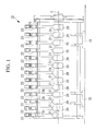
Fig. 1 is a sectional side view showing a partial configuration of an accelerator equipped with drift tubes of the present invention. - {
Fig. 2 }
Figs. 2 (a) and (b) are a front view and a sectional side view, respectively, showing the drift tube of the present invention. - {
Fig. 3 }
Figs. 3 (a), (b), and (c) are views showing a flow of a drift tube manufacturing method of the present invention. - {
Fig. 4 }
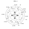
Fig. 4 is a view showing a magnet case installed in the drift tube of the present invention. - {
Fig. 5 }
Figs. 5 (a) and (b) are a front view and a sectional side view, respectively, showing a lid installed in the drift tube of the present invention. - Hereinbelow, one embodiment of a drift tube manufacturing method and a drift tube according to the present invention will be described with reference to the drawings.
As shown inFig. 1 , a drift-tube-type accelerator 10 is provided with, inside a cylindrical tube 11, a plurality ofdrift tubes 20 disposed at intervals on and along a central axis C of the tube 11.
The tube 11 is installed on the floor throughlegs 15. - As shown in
Fig. 2 , an outline of eachdrift tube 20 has an annular shape including: disc-shapedend surface parts circumferential surface part 20c formed between outer circumferential portions of theend surface parts hole 21 communicating between center parts of theend surface parts
As shown inFig. 1 , thisdrift tube 20 is suspended by a rod-like stem 23 from an upper side of the tube 11 so that the center of the through-hole 21 is positioned on the central axis C of the tube 11. - As shown in
Figs. 2 and3(c) , thedrift tube 20 is provided with: ahousing 24 having amagnet housing space 24s; amagnet case 25 housed in themagnet housing space 24s; magnets (permanent magnets) 22 which are held by themagnet case 25 on the outer circumferential side of the through-hole 21 and generate a magnetic field; and alid 27 which forms theend surface part 20b and covers theopening part 24k of themagnet housing space 24s. - As shown in
Fig. 3 (a) , thehousing 24 is formed to include: acylindrical wall part 24a forming the through-hole 21; adisc part 24b extending from one end of thecylindrical wall part 24a toward the outer circumferential side and forming theend surface part 20a; and an outercircumferential wall part 24c extending from an outer circumferential portion of thedisc part 24b, perpendicularly to a surface of thedisc part 24b, in the same direction as thecylindrical wall part 24a. Thus, in thehousing 24, the through-hole 21 is formed at the center part, and the annularmagnet housing space 24s is formed, on the outer circumferential side of the through-hole 21, surrounded by thecylindrical wall part 24a, thedisc part 24b, and the outercircumferential wall part 24c. Theopening part 24k of thismagnet housing space 24s is opened at the through-hole 21 toward an end portion (one end) 21a side which is opposite to the side where thecylindrical wall part 24a is formed.
Of thishousing 24, thedisc part 24b and the outercircumferential wall part 24c are preferably made of copper, but thecylindrical wall part 24a may be made of stainless alloy. Further, thehousing 24 itself may be made of stainless alloy, and a film of copper may be formed on the surface by electroforming. - A C-shaped
groove 28 which continues in a circumferential direction and has a portion in the circumferential direction cut off is formed in an inner circumferential surface of the outercircumferential wall part 24c of thehousing 24. An opening of thegroove 28 on the inner circumferential side is blocked by a ring-shapedmember 28r. - A
stem connection part 29 for connecting thestem 23 is formed on the outer circumferential surface side of the outercircumferential wall part 24c so as to protrude toward the outer circumference. Thisstem connection part 29 includes aconnection surface 29a to which thestem 23 is connected.
As shown inFig. 2 (a) , twocommunication holes 30 which communicate between theconnection surface 29a and thegroove 28 are formed in thestem connection part 29, and one of the communication holes 30 communicates with oneend 28a of the C-shapedgroove 28, and theother communication hole 30 communicates with the other end 28b of the C-shapedgroove 28.
Further, as shown inFig. 3 , thestem connection part 29 is formed with theconnection surface 29a and anair vent port 31 which communicates with an inner surface of the outercircumferential wall part 24c (magnet housing space 24s). - As shown in
Figs. 3 (b) and4 , themagnet case 25 forms an annular shape which fits into themagnet housing space 24s, and includes:disc parts hole part 25c formed on the inner circumferential side; and a cylindrical outercircumferential wall part 25d formed on the outer circumferential side.
The through-hole part 25c is a through-hole formed at the center parts of thedisc parts hole part 25c may be formed by additionally providing a cylindrical body at the center parts of thedisc parts
In themagnet case 25,magnet holding parts 25h which hold the plurality of (e.g., eight in the example shown inFig. 4 )magnets 22 are formed on the outer circumferential side of the through-hole part 25c at the center part. Each of themagnet holding parts 25h has a substantially trapezoidal shape in cross-section perpendicular to the axis of the through-hole part 25c, and is radially disposed with its short side directed toward the through-hole part 25c and its long side directed toward the outer circumferential side.
Thismagnet case 25 can be formed with, for example, stainless alloy. - The
magnets 22 are constituted by permanent magnets. Each of the magnets has a substantially trapezoidal cross section so as to fit in themagnet holding part 25h, and has a thickness corresponding to the clearance between thedisc parts
Themagnets 22 are arranged in the circumferential direction around the through-hole part 25c, with a magnet (permanent magnet) 22V for generating a longitudinal magnetic field and a magnet (permanent magnet) 22H for generating a transverse magnetic field disposed alternately. - The
magnets 22 and themagnet case 25 are integrally assembled into a unit beforehand.
Then, as shown inFigs. 3 (a) and (b) , themagnet case 25 in which themagnets 22 are embedded is housed in themagnet housing space 24s from the opening side of thehousing 24. A fixinghole 25f is formed in the outer circumferential portion of themagnet case 25, and themagnet case 25 is fixed to thehousing 24 by inserting a fixingbolt 32 into this fixinghole 25f and screwing the fixing bolt into thedisc part 24b of thehousing 24. - As shown in
Figs. 3 (c) and5 , thelid 27 has a disc shape and is provided so as to cover theopening part 24k of themagnet housing space 24s of thehousing 24, and anopening part 27a, into which a leading end of thecylindrical wall part 24a of thehousing 24 fits, is formed at the center part. Astep part 27c is formed on the outercircumferential portion 27b of thelid 27 so that, relative to an outer diameter on onesurface side 27f of thelid 27, an outer diameter on theother surface side 27g becomes larger. A small diameter portion D1 which is smaller than an inner diameter of themagnet housing space 24s is formed on the onesurface side 27f with respect to thestep part 27c, and a large diameter portion D2 which is larger than the inner diameter of themagnet housing space 24s is formed on theother surface side 27g with respect to thestep part 27c. - As shown in
Fig. 3 (c) , thelid 27 is mounted on thehousing 24 so as to cover theopening part 24k of themagnet housing space 24s. Then, theopening part 27a fits to thecylindrical wall part 24a, and of the outercircumferential portion 27b, the small diameter portion D1 is inserted into the outercircumferential wall part 24c while the large diameter portion D2 butts against the leading end portion of the outercircumferential wall part 24c, thereby covering theopening part 24k of themagnet housing space 24s.
Such alid 27 is preferably made of copper. - In the
lid 27, a butting portion W1 between the large diameter portion D2 and the outercircumferential wall part 24c of thehousing 24, and a butting portion W2 between the openingpart 27a of thelid 27 and the leading end portion of thecylindrical wall part 24a of thehousing 24 on the inside of the opening part are welded continuously in the circumferential direction. Here, laser beam welding is used for welding the butting portions W1 and W2 between thelid 27 and thehousing 24 on the inner circumferential side and the outer circumferential side, respectively. - As shown in
Fig. 2 , thestem 23 for fixing thedrift tube 20 to the tube 11 has a cylindrical shape and is provided, inside thereof, with twopipes 81 having leadingend portions 81a respectively connected to the twocommunication holes 30 at theconnection surface 29a. An external cooling water supply pump (not shown) is connected to one of the twopipes 81, and a tank, or the like (not shown), for recovering cooling water is connected to theother pipe 81. Thus, the cooling water is circulated through thegroove 28 so as to cool thedrift tube 20.
Instead of the twopipes 81, one double pipe may be used such that, for example, the external cooling water supply pump (not shown) is connected to a pipe line on an inner side (center side) and the tank, or the like (not shown), for recovering the cooling water is connected to a pipe line on an outer side (outer circumferential side). - The
air vent port 31 having one end thereof facing theconnection surface 29a communicates with an inner space of thestem 23 and releases heat from themagnet housing space 24s during welding. - One
end 23a side of thisstem 23 is butted against thestem connection part 29 and welded by electron beam welding on the outer circumferential surface. As shown inFig. 1 , theother end 23b of thestem 23 penetrates the upper side of the tube 11 and is fixed so as to protrude toward the outer circumferential side of the tube 11, and thepipes 81 and the like are connected to the cooling water supply pump, the tank, or the like, outside the tube 11. - In the
accelerator 10 equipped with such adrift tube 20, a particle beam such as a proton beam and an ion beam generated by a beam generator (not shown) is accelerated in the tube 11 and fired at a target (not shown) to thereby carry out experiments and the like. At this time, since otherwise the particle beam is diffused in the tube 11, the particle beam is directed through the through-hole 21 of thedrift tube 20 so that the particle beam is focused by the magnetic fields generated by themagnets 22. - To assemble this
drift tube 20, the predetermined number ofmagnets 22 are housed in themagnet case 25 beforehand.
Then, themagnet case 25 is housed in and fixed to themagnet housing space 24s from the opening side of thehousing 24, and thereafter thelid 27 is set on thehousing 24 so as to cover theopening part 24k of themagnet housing space 24s.
In this state, the butting portion W1 between the large diameter portion D2 of thelid 27 and the outercircumferential wall part 24c of thehousing 24, and the butting portion W2 between the openingpart 27a of thelid 27 and the leading end portion of thecylindrical wall part 24a of thehousing 24 on the inside of the opening part are welded by laser beam welding continuously in the circumferential direction. Thereby, thedrift tube 20 is formed. - Thereafter, the one
end 23a of thestem 23 is butted against thestem connection part 29 of thedrift tube 20 and these are welded together by electron beam welding. - According to the above-described configuration, by using the permanent magnet instead of the electromagnet as the
magnet 22 of thedrift tube 20, the need for an external power supply, and wiring, an insulating member, and the like, inside thedrift tube 20 is eliminated, and thereby it is possible to simplify the structure and reduce the cost.
Here, thehousing 24 for housing themagnets 22 and thelid 27 are formed of copper. Compared to a case where thehousing 24 and thelid 27 are formed of stainless alloy, since copper has high thermal conductivity, the cooling efficiency is higher and the temperature is less likely to increase. Therefore, since the temperature rise becomes smaller relative to the amount of heat which is generated on the surface of thehousing 24 by the particle beam during operation of theaccelerator 10, demagnetization of themagnets 22 as well as thermal strain can be suppressed.
Moreover, in a case where electron beam welding is used for welding thehousing 24 and thelid 27, since electron beam welding is performed under vacuum, heat cannot be released and the effect of the temperature rise due to welding increases. In the present embodiment, however, laser beam welding is used for welding thehousing 24 and thelid 27. Since laser beam welding can be performed in the atmosphere, it is excellent in heat dissipation and the thermal effect can be more reliably suppressed.
In addition, in electron beam welding, due to a magnetic force of themagnets 22 constituted by the permanent magnets, the electron beam is bent and weld beads are not formed along the shape of thelid 27, which can degrade the welding quality. In the present embodiment, however, since laser beam welding is used for welding thehousing 24 and thelid 27, welding can be performed with good quality and without any influence of themagnets 22.
Thus, in thedrift tube 20, it is possible to reduce the cost while securing an adequate level of particle beam focusing performance. - Moreover, the
magnets 22 and themagnet case 25 are integrally assembled into a unit beforehand. Since this allows themagnets 22 to be set with accuracy, the stable, high performance of thedrift tube 20 can be realized. Further, the assembly becomes easy, which contributes to cost reduction of thedrift tube 20. - In the above-described embodiment, any other configuration may be adopted for configurations of those other than the
drift tube 20, such as thestem 23 or theentire accelerator 10, without departing from the scope of the present invention. -
- 10
- accelerator
- 11
- tube
- 20
- drift tube
- 20a, 20b
- end surface part
- 20c
- outer circumferential surface part
- 21
- through-hole
- 21a
- end part (one end)
- 22, 22H, 22V
- magnet (permanent magnet)
- 23
- stem
- 23a
- one end
- 23b
- other end
- 24
- housing
- 24a
- cylindrical wall part
- 24b
- disc part
- 24c
- outer circumferential wall part
- 24k
- opening part
- 24s
- magnet housing space
- 25
- magnet case
- 25a, 25b
- disc part
- 25c
- through-hole part
- 25d
- outer circumferential wall part
- 25h
- magnet holding part
- 25f
- fixing hole
- 27
- lid
- 27a
- opening part
- 27b
- outer circumferential portion
- 27c
- step part
- 27f
- one surface side
- 27g
- other surface side
- 28
- groove
- 28a
- one end
- 28b
- other end
- 29
- stem connection part
- 29a
- connection surface
- 30
- communication hole
- 31
- air vent port
- 32
- fixing bolt
- 81
- pipe
- 81a
- leading end portion
- D1
- small diameter portion
- D2
- large diameter portion
Claims (4)
- A manufacturing method of a drift tube installed in a drift-tube-type accelerator, comprising:a magnet housing stage of housing a predetermined number of permanent magnets in a housing, which has a through-hole at a center part and an annular magnet housing space on an outer circumferential side of the through-hole, from an opening part of the magnet housing space into the magnet housing space; anda welding stage of setting a lid for covering the opening part on the opening part, and welding the lid and the housing by laser beam welding, whereinat least a surface of the housing and a surface of the lid are formed of copper.
- The manufacturing method of a drift tube according to Claim 1, wherein
the housing includes the opening part at one end side of the through-hole, and
in the welding stage, at least an inner circumferential portion of the lid and a portion around the through-hole of the housing are welded by laser beam welding. - The manufacturing method of a drift tube according to Claim 1 or 2, wherein
in the magnet housing stage, the predetermined number of permanent magnets are housed in a magnet case, and the magnet case is housed in the magnet housing space. - A drift tube installed in a drift-tube-type accelerator, comprising:a housing which has a through-hole at a center part and is formed with an annular magnet housing space, which has an opening part on one end side of the through-hole, on an outer circumferential side of the through-hole;a predetermined number of permanent magnets housed in the magnet housing space; anda lid covering the opening part and welded to the housing, wherein,at least a surface of the housing and a surface of the lid are formed of copper.
Applications Claiming Priority (1)
| Application Number | Priority Date | Filing Date | Title |
|---|---|---|---|
| JP2012250330A JP5726154B2 (en) | 2012-11-14 | 2012-11-14 | Drift tube manufacturing method, drift tube |
Publications (2)
| Publication Number | Publication Date |
|---|---|
| EP2734016A1 true EP2734016A1 (en) | 2014-05-21 |
| EP2734016B1 EP2734016B1 (en) | 2019-07-03 |
Family
ID=49356248
Family Applications (1)
| Application Number | Title | Priority Date | Filing Date |
|---|---|---|---|
| EP13188266.4A Active EP2734016B1 (en) | 2012-11-14 | 2013-10-11 | Drift tube manufacturing method and drift tube |
Country Status (3)
| Country | Link |
|---|---|
| US (1) | US9029796B2 (en) |
| EP (1) | EP2734016B1 (en) |
| JP (1) | JP5726154B2 (en) |
Families Citing this family (3)
| Publication number | Priority date | Publication date | Assignee | Title |
|---|---|---|---|---|
| CN109819579B (en) * | 2019-02-02 | 2021-04-20 | 中国科学院近代物理研究所 | Mechanical structure of a high-frequency electro-focusing ion acceleration device and assembling method thereof |
| US11483920B2 (en) * | 2019-12-13 | 2022-10-25 | Jefferson Science Associates, Llc | High efficiency normal conducting linac for environmental water remediation |
| CN111560610A (en) * | 2020-04-16 | 2020-08-21 | 江苏大学 | A method for repairing titanium alloy aircraft bearing beams by alternating magnetic field assisted laser deposition |
Citations (2)
| Publication number | Priority date | Publication date | Assignee | Title |
|---|---|---|---|---|
| JPH04108900U (en) | 1991-03-07 | 1992-09-21 | 三菱重工業株式会社 | Accelerator drift tube |
| JPH11329795A (en) | 1998-05-11 | 1999-11-30 | Mitsubishi Heavy Ind Ltd | Drift tube and manufacture thereof |
Family Cites Families (8)
| Publication number | Priority date | Publication date | Assignee | Title |
|---|---|---|---|---|
| US4658109A (en) * | 1986-05-15 | 1987-04-14 | The United States Of America As Represented By The Secretary Of The Army | Cylindrical laser welder |
| JPH03289097A (en) * | 1990-04-04 | 1991-12-19 | Mitsubishi Heavy Ind Ltd | Manufacture of drift tube outer cover for accelerator |
| JPH04289698A (en) * | 1991-03-19 | 1992-10-14 | Mitsubishi Heavy Ind Ltd | Drift tube |
| US6404089B1 (en) * | 2000-07-21 | 2002-06-11 | Mark R. Tomion | Electrodynamic field generator |
| JP2007174803A (en) * | 2005-12-22 | 2007-07-05 | Iai:Kk | Linear motor and linear motor stator manufacturing method |
| JP5010846B2 (en) * | 2006-04-19 | 2012-08-29 | 株式会社日立製作所 | Accelerator |
| JP2009065746A (en) * | 2007-09-05 | 2009-03-26 | Teikoku Electric Mfg Co Ltd | Canned motor drive system |
| WO2011154563A1 (en) * | 2010-06-09 | 2011-12-15 | Fundacion Tekniker | Drift tube for linear accelerator (linac) with four-pole permanent magnets without welded caps |
-
2012
- 2012-11-14 JP JP2012250330A patent/JP5726154B2/en active Active
-
2013
- 2013-10-07 US US14/047,258 patent/US9029796B2/en active Active
- 2013-10-11 EP EP13188266.4A patent/EP2734016B1/en active Active
Patent Citations (2)
| Publication number | Priority date | Publication date | Assignee | Title |
|---|---|---|---|---|
| JPH04108900U (en) | 1991-03-07 | 1992-09-21 | 三菱重工業株式会社 | Accelerator drift tube |
| JPH11329795A (en) | 1998-05-11 | 1999-11-30 | Mitsubishi Heavy Ind Ltd | Drift tube and manufacture thereof |
Non-Patent Citations (4)
| Title |
|---|
| D.A.KASHINSKY: "First Section of a 352 MHz Prototype Alvarez DTL Tank for the CERN SPL", PROCEEDINGS OF EPAC06, 2006, pages 1621 - 1623, XP002719144 * |
| E.O.BALLARD ET AL: "Ground test accelerator (GTA) Drift Tube Linac (DTL) fabrication and assembly status", PROCEEDINGS OF LINAC92, vol. 1, 1992, pages 395 - 397, XP002719146 * |
| HANSBOROUGH ET AL: "Mechanical Technologies for the PIGMI", PROCEEDINGS OF 1979 PAC, vol. 26, no. 3, June 1979 (1979-06-01), pages 3770 - 3772, XP002719145, ISSN: 0018-9499 * |
| M.VRETENAR ET AL: "Design and Development of RF Structures for Linac4", PROCEEDINGS OF LINAC06, 2006, pages 679 - 681, XP002719147 * |
Also Published As
| Publication number | Publication date |
|---|---|
| US9029796B2 (en) | 2015-05-12 |
| JP5726154B2 (en) | 2015-05-27 |
| EP2734016B1 (en) | 2019-07-03 |
| JP2014099318A (en) | 2014-05-29 |
| US20140132374A1 (en) | 2014-05-15 |
Similar Documents
| Publication | Publication Date | Title |
|---|---|---|
| US8761344B2 (en) | Small x-ray tube with electron beam control optics | |
| US9029796B2 (en) | Drift tube manufacturing method and drift tube | |
| JP4548523B2 (en) | Assembly method for indirectly heated cathode | |
| JP5801161B2 (en) | X-ray tube and method of manufacturing X-ray tube | |
| CN220543832U (en) | Ion source equipment and coating system | |
| JP4805656B2 (en) | Multi-beam klystron equipment | |
| JP2007095667A (en) | X-ray tube | |
| JP2016041974A (en) | Vacuum device and feed-through structure | |
| JP6081589B2 (en) | Cooling configuration for X-ray generator | |
| CN118352207A (en) | Method for manufacturing industrial magnetron | |
| US5821693A (en) | Electron beam tubes having a unitary envelope having stepped inner surface | |
| JP6096063B2 (en) | cyclotron | |
| WO2011111396A1 (en) | Magnetron, and device using microwaves | |
| JP2009158365A (en) | Cathode holding structure and ion source equipped with the same | |
| JP4994995B2 (en) | Magnet generator | |
| JP4557681B2 (en) | Sputter ion pump | |
| JP5313519B2 (en) | Magnetron | |
| KR102026129B1 (en) | Quadrupole Magnet Assembly for Beam Alignment | |
| RU2397626C1 (en) | Resonance accelerator drift tube | |
| JP2011228465A (en) | Superconducting magnet device | |
| JP2026515096A (en) | Sputter ion pump module and vacuum pump | |
| CN111140453B (en) | An annular magnetic steel installation structure for the cone section of an ion thruster | |
| KR20150000078U (en) | A terminal assembly for motor having waterproof function | |
| JP4894173B2 (en) | Magnetron | |
| CN219696906U (en) | Protective cover for laser |
Legal Events
| Date | Code | Title | Description |
|---|---|---|---|
| PUAI | Public reference made under article 153(3) epc to a published international application that has entered the european phase |
Free format text: ORIGINAL CODE: 0009012 |
|
| 17P | Request for examination filed |
Effective date: 20131011 |
|
| AK | Designated contracting states |
Kind code of ref document: A1 Designated state(s): AL AT BE BG CH CY CZ DE DK EE ES FI FR GB GR HR HU IE IS IT LI LT LU LV MC MK MT NL NO PL PT RO RS SE SI SK SM TR |
|
| AX | Request for extension of the european patent |
Extension state: BA ME |
|
| R17P | Request for examination filed (corrected) |
Effective date: 20141118 |
|
| RBV | Designated contracting states (corrected) |
Designated state(s): AL AT BE BG CH CY CZ DE DK EE ES FI FR GB GR HR HU IE IS IT LI LT LU LV MC MK MT NL NO PL PT RO RS SE SI SK SM TR |
|
| RAP1 | Party data changed (applicant data changed or rights of an application transferred) |
Owner name: MITSUBISHI HEAVY INDUSTRIES MECHATRONICS SYSTEMS, |
|
| RAP1 | Party data changed (applicant data changed or rights of an application transferred) |
Owner name: MITSUBISHI HEAVY INDUSTRIES MACHINERY SYSTEMS, LTD |
|
| STAA | Information on the status of an ep patent application or granted ep patent |
Free format text: STATUS: EXAMINATION IS IN PROGRESS |
|
| 17Q | First examination report despatched |
Effective date: 20181120 |
|
| GRAP | Despatch of communication of intention to grant a patent |
Free format text: ORIGINAL CODE: EPIDOSNIGR1 |
|
| STAA | Information on the status of an ep patent application or granted ep patent |
Free format text: STATUS: GRANT OF PATENT IS INTENDED |
|
| INTG | Intention to grant announced |
Effective date: 20190108 |
|
| GRAS | Grant fee paid |
Free format text: ORIGINAL CODE: EPIDOSNIGR3 |
|
| GRAA | (expected) grant |
Free format text: ORIGINAL CODE: 0009210 |
|
| STAA | Information on the status of an ep patent application or granted ep patent |
Free format text: STATUS: THE PATENT HAS BEEN GRANTED |
|
| AK | Designated contracting states |
Kind code of ref document: B1 Designated state(s): AL AT BE BG CH CY CZ DE DK EE ES FI FR GB GR HR HU IE IS IT LI LT LU LV MC MK MT NL NO PL PT RO RS SE SI SK SM TR |
|
| REG | Reference to a national code |
Ref country code: GB Ref legal event code: FG4D |
|
| REG | Reference to a national code |
Ref country code: CH Ref legal event code: EP Ref country code: AT Ref legal event code: REF Ref document number: 1152558 Country of ref document: AT Kind code of ref document: T Effective date: 20190715 |
|
| REG | Reference to a national code |
Ref country code: DE Ref legal event code: R096 Ref document number: 602013057327 Country of ref document: DE |
|
| REG | Reference to a national code |
Ref country code: IE Ref legal event code: FG4D |
|
| REG | Reference to a national code |
Ref country code: NL Ref legal event code: MP Effective date: 20190703 |
|
| REG | Reference to a national code |
Ref country code: LT Ref legal event code: MG4D |
|
| REG | Reference to a national code |
Ref country code: AT Ref legal event code: MK05 Ref document number: 1152558 Country of ref document: AT Kind code of ref document: T Effective date: 20190703 |
|
| PG25 | Lapsed in a contracting state [announced via postgrant information from national office to epo] |
Ref country code: NO Free format text: LAPSE BECAUSE OF FAILURE TO SUBMIT A TRANSLATION OF THE DESCRIPTION OR TO PAY THE FEE WITHIN THE PRESCRIBED TIME-LIMIT Effective date: 20191003 Ref country code: BG Free format text: LAPSE BECAUSE OF FAILURE TO SUBMIT A TRANSLATION OF THE DESCRIPTION OR TO PAY THE FEE WITHIN THE PRESCRIBED TIME-LIMIT Effective date: 20191003 Ref country code: NL Free format text: LAPSE BECAUSE OF FAILURE TO SUBMIT A TRANSLATION OF THE DESCRIPTION OR TO PAY THE FEE WITHIN THE PRESCRIBED TIME-LIMIT Effective date: 20190703 Ref country code: PT Free format text: LAPSE BECAUSE OF FAILURE TO SUBMIT A TRANSLATION OF THE DESCRIPTION OR TO PAY THE FEE WITHIN THE PRESCRIBED TIME-LIMIT Effective date: 20191104 Ref country code: CZ Free format text: LAPSE BECAUSE OF FAILURE TO SUBMIT A TRANSLATION OF THE DESCRIPTION OR TO PAY THE FEE WITHIN THE PRESCRIBED TIME-LIMIT Effective date: 20190703 Ref country code: AT Free format text: LAPSE BECAUSE OF FAILURE TO SUBMIT A TRANSLATION OF THE DESCRIPTION OR TO PAY THE FEE WITHIN THE PRESCRIBED TIME-LIMIT Effective date: 20190703 Ref country code: LT Free format text: LAPSE BECAUSE OF FAILURE TO SUBMIT A TRANSLATION OF THE DESCRIPTION OR TO PAY THE FEE WITHIN THE PRESCRIBED TIME-LIMIT Effective date: 20190703 Ref country code: FI Free format text: LAPSE BECAUSE OF FAILURE TO SUBMIT A TRANSLATION OF THE DESCRIPTION OR TO PAY THE FEE WITHIN THE PRESCRIBED TIME-LIMIT Effective date: 20190703 Ref country code: HR Free format text: LAPSE BECAUSE OF FAILURE TO SUBMIT A TRANSLATION OF THE DESCRIPTION OR TO PAY THE FEE WITHIN THE PRESCRIBED TIME-LIMIT Effective date: 20190703 Ref country code: SE Free format text: LAPSE BECAUSE OF FAILURE TO SUBMIT A TRANSLATION OF THE DESCRIPTION OR TO PAY THE FEE WITHIN THE PRESCRIBED TIME-LIMIT Effective date: 20190703 |
|
| PG25 | Lapsed in a contracting state [announced via postgrant information from national office to epo] |
Ref country code: ES Free format text: LAPSE BECAUSE OF FAILURE TO SUBMIT A TRANSLATION OF THE DESCRIPTION OR TO PAY THE FEE WITHIN THE PRESCRIBED TIME-LIMIT Effective date: 20190703 Ref country code: AL Free format text: LAPSE BECAUSE OF FAILURE TO SUBMIT A TRANSLATION OF THE DESCRIPTION OR TO PAY THE FEE WITHIN THE PRESCRIBED TIME-LIMIT Effective date: 20190703 Ref country code: LV Free format text: LAPSE BECAUSE OF FAILURE TO SUBMIT A TRANSLATION OF THE DESCRIPTION OR TO PAY THE FEE WITHIN THE PRESCRIBED TIME-LIMIT Effective date: 20190703 Ref country code: IS Free format text: LAPSE BECAUSE OF FAILURE TO SUBMIT A TRANSLATION OF THE DESCRIPTION OR TO PAY THE FEE WITHIN THE PRESCRIBED TIME-LIMIT Effective date: 20191103 Ref country code: GR Free format text: LAPSE BECAUSE OF FAILURE TO SUBMIT A TRANSLATION OF THE DESCRIPTION OR TO PAY THE FEE WITHIN THE PRESCRIBED TIME-LIMIT Effective date: 20191004 Ref country code: RS Free format text: LAPSE BECAUSE OF FAILURE TO SUBMIT A TRANSLATION OF THE DESCRIPTION OR TO PAY THE FEE WITHIN THE PRESCRIBED TIME-LIMIT Effective date: 20190703 |
|
| PG25 | Lapsed in a contracting state [announced via postgrant information from national office to epo] |
Ref country code: TR Free format text: LAPSE BECAUSE OF FAILURE TO SUBMIT A TRANSLATION OF THE DESCRIPTION OR TO PAY THE FEE WITHIN THE PRESCRIBED TIME-LIMIT Effective date: 20190703 |
|
| PG25 | Lapsed in a contracting state [announced via postgrant information from national office to epo] |
Ref country code: DK Free format text: LAPSE BECAUSE OF FAILURE TO SUBMIT A TRANSLATION OF THE DESCRIPTION OR TO PAY THE FEE WITHIN THE PRESCRIBED TIME-LIMIT Effective date: 20190703 Ref country code: PL Free format text: LAPSE BECAUSE OF FAILURE TO SUBMIT A TRANSLATION OF THE DESCRIPTION OR TO PAY THE FEE WITHIN THE PRESCRIBED TIME-LIMIT Effective date: 20190703 Ref country code: EE Free format text: LAPSE BECAUSE OF FAILURE TO SUBMIT A TRANSLATION OF THE DESCRIPTION OR TO PAY THE FEE WITHIN THE PRESCRIBED TIME-LIMIT Effective date: 20190703 Ref country code: RO Free format text: LAPSE BECAUSE OF FAILURE TO SUBMIT A TRANSLATION OF THE DESCRIPTION OR TO PAY THE FEE WITHIN THE PRESCRIBED TIME-LIMIT Effective date: 20190703 |
|
| PG25 | Lapsed in a contracting state [announced via postgrant information from national office to epo] |
Ref country code: MC Free format text: LAPSE BECAUSE OF FAILURE TO SUBMIT A TRANSLATION OF THE DESCRIPTION OR TO PAY THE FEE WITHIN THE PRESCRIBED TIME-LIMIT Effective date: 20190703 Ref country code: IS Free format text: LAPSE BECAUSE OF FAILURE TO SUBMIT A TRANSLATION OF THE DESCRIPTION OR TO PAY THE FEE WITHIN THE PRESCRIBED TIME-LIMIT Effective date: 20200224 Ref country code: SK Free format text: LAPSE BECAUSE OF FAILURE TO SUBMIT A TRANSLATION OF THE DESCRIPTION OR TO PAY THE FEE WITHIN THE PRESCRIBED TIME-LIMIT Effective date: 20190703 Ref country code: SM Free format text: LAPSE BECAUSE OF FAILURE TO SUBMIT A TRANSLATION OF THE DESCRIPTION OR TO PAY THE FEE WITHIN THE PRESCRIBED TIME-LIMIT Effective date: 20190703 |
|
| REG | Reference to a national code |
Ref country code: CH Ref legal event code: PL |
|
| REG | Reference to a national code |
Ref country code: DE Ref legal event code: R097 Ref document number: 602013057327 Country of ref document: DE |
|
| PLBE | No opposition filed within time limit |
Free format text: ORIGINAL CODE: 0009261 |
|
| STAA | Information on the status of an ep patent application or granted ep patent |
Free format text: STATUS: NO OPPOSITION FILED WITHIN TIME LIMIT |
|
| PG2D | Information on lapse in contracting state deleted |
Ref country code: IS |
|
| PG25 | Lapsed in a contracting state [announced via postgrant information from national office to epo] |
Ref country code: LU Free format text: LAPSE BECAUSE OF NON-PAYMENT OF DUE FEES Effective date: 20191011 Ref country code: CH Free format text: LAPSE BECAUSE OF NON-PAYMENT OF DUE FEES Effective date: 20191031 Ref country code: LI Free format text: LAPSE BECAUSE OF NON-PAYMENT OF DUE FEES Effective date: 20191031 |
|
| 26N | No opposition filed |
Effective date: 20200603 |
|
| REG | Reference to a national code |
Ref country code: BE Ref legal event code: MM Effective date: 20191031 |
|
| PG25 | Lapsed in a contracting state [announced via postgrant information from national office to epo] |
Ref country code: SI Free format text: LAPSE BECAUSE OF FAILURE TO SUBMIT A TRANSLATION OF THE DESCRIPTION OR TO PAY THE FEE WITHIN THE PRESCRIBED TIME-LIMIT Effective date: 20190703 Ref country code: BE Free format text: LAPSE BECAUSE OF NON-PAYMENT OF DUE FEES Effective date: 20191031 |
|
| PG25 | Lapsed in a contracting state [announced via postgrant information from national office to epo] |
Ref country code: IE Free format text: LAPSE BECAUSE OF NON-PAYMENT OF DUE FEES Effective date: 20191011 |
|
| PG25 | Lapsed in a contracting state [announced via postgrant information from national office to epo] |
Ref country code: CY Free format text: LAPSE BECAUSE OF FAILURE TO SUBMIT A TRANSLATION OF THE DESCRIPTION OR TO PAY THE FEE WITHIN THE PRESCRIBED TIME-LIMIT Effective date: 20190703 |
|
| PG25 | Lapsed in a contracting state [announced via postgrant information from national office to epo] |
Ref country code: MT Free format text: LAPSE BECAUSE OF FAILURE TO SUBMIT A TRANSLATION OF THE DESCRIPTION OR TO PAY THE FEE WITHIN THE PRESCRIBED TIME-LIMIT Effective date: 20190703 Ref country code: HU Free format text: LAPSE BECAUSE OF FAILURE TO SUBMIT A TRANSLATION OF THE DESCRIPTION OR TO PAY THE FEE WITHIN THE PRESCRIBED TIME-LIMIT; INVALID AB INITIO Effective date: 20131011 |
|
| PG25 | Lapsed in a contracting state [announced via postgrant information from national office to epo] |
Ref country code: MK Free format text: LAPSE BECAUSE OF FAILURE TO SUBMIT A TRANSLATION OF THE DESCRIPTION OR TO PAY THE FEE WITHIN THE PRESCRIBED TIME-LIMIT Effective date: 20190703 |
|
| PGFP | Annual fee paid to national office [announced via postgrant information from national office to epo] |
Ref country code: IT Payment date: 20250922 Year of fee payment: 13 |
|
| PGFP | Annual fee paid to national office [announced via postgrant information from national office to epo] |
Ref country code: GB Payment date: 20250828 Year of fee payment: 13 |
|
| PGFP | Annual fee paid to national office [announced via postgrant information from national office to epo] |
Ref country code: FR Payment date: 20250908 Year of fee payment: 13 |
|
| PGFP | Annual fee paid to national office [announced via postgrant information from national office to epo] |
Ref country code: DE Payment date: 20250902 Year of fee payment: 13 |