EP2733839A1 - Electric circuit with one power amplifier for antagonistic piezoelectric actuators - Google Patents
Electric circuit with one power amplifier for antagonistic piezoelectric actuators Download PDFInfo
- Publication number
- EP2733839A1 EP2733839A1 EP12400047.2A EP12400047A EP2733839A1 EP 2733839 A1 EP2733839 A1 EP 2733839A1 EP 12400047 A EP12400047 A EP 12400047A EP 2733839 A1 EP2733839 A1 EP 2733839A1
- Authority
- EP
- European Patent Office
- Prior art keywords
- piezoelectric actuators
- power amplifier
- electric circuit
- circuit according
- resistors
- Prior art date
- Legal status (The legal status is an assumption and is not a legal conclusion. Google has not performed a legal analysis and makes no representation as to the accuracy of the status listed.)
- Granted
Links
Images
Classifications
-
- H—ELECTRICITY
- H02—GENERATION; CONVERSION OR DISTRIBUTION OF ELECTRIC POWER
- H02N—ELECTRIC MACHINES NOT OTHERWISE PROVIDED FOR
- H02N2/00—Electric machines in general using piezoelectric effect, electrostriction or magnetostriction
- H02N2/02—Electric machines in general using piezoelectric effect, electrostriction or magnetostriction producing linear motion, e.g. actuators; Linear positioners ; Linear motors
- H02N2/06—Drive circuits; Control arrangements or methods
- H02N2/065—Large signal circuits, e.g. final stages
-
- B—PERFORMING OPERATIONS; TRANSPORTING
- B64—AIRCRAFT; AVIATION; COSMONAUTICS
- B64C—AEROPLANES; HELICOPTERS
- B64C27/00—Rotorcraft; Rotors peculiar thereto
- B64C27/54—Mechanisms for controlling blade adjustment or movement relative to rotor head, e.g. lag-lead movement
- B64C27/72—Means acting on blades
- B64C2027/7205—Means acting on blades on each blade individually, e.g. individual blade control [IBC]
- B64C2027/7261—Means acting on blades on each blade individually, e.g. individual blade control [IBC] with flaps
- B64C2027/7266—Means acting on blades on each blade individually, e.g. individual blade control [IBC] with flaps actuated by actuators
- B64C2027/7283—Means acting on blades on each blade individually, e.g. individual blade control [IBC] with flaps actuated by actuators of the piezoelectric type
-
- B—PERFORMING OPERATIONS; TRANSPORTING
- B64—AIRCRAFT; AVIATION; COSMONAUTICS
- B64C—AEROPLANES; HELICOPTERS
- B64C27/00—Rotorcraft; Rotors peculiar thereto
- B64C27/001—Vibration damping devices
-
- Y—GENERAL TAGGING OF NEW TECHNOLOGICAL DEVELOPMENTS; GENERAL TAGGING OF CROSS-SECTIONAL TECHNOLOGIES SPANNING OVER SEVERAL SECTIONS OF THE IPC; TECHNICAL SUBJECTS COVERED BY FORMER USPC CROSS-REFERENCE ART COLLECTIONS [XRACs] AND DIGESTS
- Y02—TECHNOLOGIES OR APPLICATIONS FOR MITIGATION OR ADAPTATION AGAINST CLIMATE CHANGE
- Y02T—CLIMATE CHANGE MITIGATION TECHNOLOGIES RELATED TO TRANSPORTATION
- Y02T50/00—Aeronautics or air transport
- Y02T50/30—Wing lift efficiency
Definitions
- the invention is related to an electric circuit with one power amplifier for two piezoelectric actuators and said invention particularly belongs to the field of power electronics for piezoelectric actuators, in particular for helicopters.
- Piezoelectric actuators have the advantage of a high actuating precision and a fast reaction. Piezoelectric actuators are components with a high electrical capacity whereby only part of the electrical energy supplied to the actuators is converted to mechanical energy. A large part of this energy is stored in the piezoelectric actuator functioning as a capacitor.
- the document US 2008/0316671 A1 discloses a piezoelectric actuator with an amplifier for a piezo arrangement based on pulse-width modulation (PWM) using switches SW in combination with inductors L.
- the inductors are used as low pass filters to buffer energy at high frequency of PWM, e.g. in the order of 20 kHz.
- a detailed PWM generation scheme is disclosed with independent charging and discharging circuits. Only unipolar operation is possible.
- the document US 20050285477 A1 discloses two piezo-elements which are driven with two voltages having a phase difference.
- One of the piezo-elements is charged by an inductive step-up means to a voltage exceeding an available power supply voltage. Subsequent charge, i.e. energy is transferred from the one piezo-element to the other piezo-element by an inductive element. Only unipolar operation is possible.
- US 20050280332 A1 discloses two piezo-elements of a piezoelectric actuator which are driven with two voltages having a mutual phase difference.
- One of said piezo-elements is charged by a capacitive voltage step-up means to a voltage exceeding an available power supply voltage.
- a capacitor is coupled to the piezo-element, which divides the voltage of the piezo-element and simultaneously transfers part of the energy stored in the piezo-element to said capacitor. A part of the energy transferred to said capacitor is later transferred back to said piezo-element, providing an energy-saving feature.
- the second piezo-element is driven in a similar way providing the required phase difference. According to US 20050285477 A1 and US 20050280332 A1 there are respectively 2 amplifiers for 2 piezo-elements.
- the document US 6 411 009 A discloses a piezoelectric actuator with at least two piezoelectric actuator elements connected in series with each other mechanically and electrically. Said two piezoelectric actuator elements form a half bridge in an amplifier bridge circuit having a further half bridge formed by two series connected electronic switches which are operated or clocked by a control circuit such as a pulse modulator circuit for periodically energizing the piezoelectric actuators in push-pull fashion.
- a choke is connected between a first junction point of the two piezoelectric actuators and a second junction point between the two electronic switches for assuring a loss free reverse charging of the two piezoelectric actuators functioning as electrical capacitors in the energizing bridge circuit.
- the choke functions as energy storage and the stored energy is used in the push-pull charging of the capacitors formed by the piezoelectric elements.
- the choke is used as low-pass filter to suppress the oscillations of a pulse width modulator generated by two switches driving the two piezoelectric actuator elements.
- the piezoelectric actuator according to US 6 411 009 A allows only unipolar operation.
- the objective of the present invention is to provide a simple and reliable electric circuit for two piezoelectric actuators adapted to an actuation frequency from 7 Hz to 35 Hz or even 42 Hz and with an energy storage.
- an electric circuit with one power amplifier for at least two or any even number of piezoelectric actuators is provided.
- Said at least two or any even number of piezoelectric actuators are in preferably antagonist arrangement connected mechanically in series with each other.
- Said at least two or any even number of piezoelectric actuators are interconnected as well electrically and operated by the one power amplifier, said one power amplifier (V1) being commanded by a control circuit for time-variant energizing the at least two or any even number of piezoelectric actuators respectively in push-pull fashion.
- Said power amplifier is connected to a junction point between the at least two or any even number of piezoelectric actuators and said power amplifier is connected to a one directional diode.
- At least one buffer capacitor preferably a DC link capacitor, is provided downstream the one directional diode with regard to the power amplifier.
- the at least one buffer capacitor buffers preferably the blind power from the piezoelectric actuators which corresponds to charging and discharging of the capacitance of said piezoelectric actuators at "power supply" level at a frequency of blind power corresponding to the frequency of actuation, e.g. in the order of 7Hz to 35 Hz for four bladed rotors or up to 42Hz for five bladed rotors.
- the inductances as used in the state of the art do not buffer energy at said low frequencies unless at the prize of too large inductances.
- the inventive electric circuit allows an option for bipolar operation of preferably two antagonist piezoelectric actuators.
- its two piezoelectric actuators are driven by one power amplifier, a capacitor and a diode, i. e. two passive components instead of two active components, namely amplifiers and/or complex voltage stabilizing feedback loops as disclosed in the state of the art.
- the inventive electric circuit is a less complex solution at lower weight and lower costs than the state of the art.
- There are minimal electrical loads at the piezoelectric actuators of the inventive electric circuit thanks to a self-adjusting offset voltage and only two cables from the amplifier to the piezoelectric actuators and from the intermediate buffer capacitor.
- the invention allows economy with regard to mass, size and costs by using mainly passive components like resistors and capacitors instead of the inductances of the state of the art tending to be large and heavy.
- the inventive electric circuit simplifies the cabling, which is particularly advantageous for piezoelectric actuators arranged inside helicopter rotor blades.
- the inventive electric circuit is applicable for all piezoelectric actuators, in particular in the field of helicopters, especially if 2 piezoelectric actuators are working in antagonist fashion.
- the inventive electric circuit can deal with nearly any power amplifier, including PWM technology and allows division of the voltage based on one single amplifier and to buffer fluctuating power by adding components around the amplifier namely at least one additional DC link capacitor and a voltage divider in order to be able to drive piezoelectric actuators in a preferably antagonist arrangement.
- At least one protection resistor is provided between said one power amplifier and said at least two piezoelectric actuators.
- the protection resistor is provided between said one power amplifier and said at least two piezoelectric actuators to shield said piezoelectric actuators from any sudden jumps of electric power from the power amplifier, said jumps of electric power being an inherent risk for the mechanic operating ability of the a piezoelectric actuators as said sudden jumps of electric power may lead to an immediate failure of the piezoelectric actuator due to tensile stresses and resulting mechanical cracks causing a reliability problem for any system controlled by an electric circuit with piezoelectric actuators.
- a robust electric circuit at activation/deactivation operation is provided due to protection of the piezoelectric actuators by the at least one protection resistor.
- At least one further protection resistor is provided between said at least two piezoelectric actuators.
- the at least one further protection resistor At the electric failure such as a short circuit of one of the at least two piezoelectric actuators acting against each other in antagonist arrangement the at least one further protection resistor attenuates propagation of any excessive electric power to the other piezoelectric actuator thus shielding said other piezoelectric actuator from any sudden jumps of electric power resulting from the short circuited piezoelectric actuator making the inventive electric circuit failure tolerant for any supposed electric failure of one of the at least two piezoelectric actuators.
- the failure of one of the at least two piezoelectric actuators is not leading to a failure propagation transmitted via the electrical network and the power amplifier to the other of the at least two piezoelectric actuators thus improving reliability of the system controlled by the inventive electric circuit with piezoelectric actuators and avoiding repair.
- a robust electric circuit is provided due to protection of the piezoelectric actuators from each other by the at least one further protection resistor in case of an electric failure of one of the at least two piezoelectric actuators.
- the time-variance of the power amplifier is based on pulse-width modulation (PWM) for less thermal losses.
- PWM pulse-width modulation
- two static resistors and two buffer capacitors are provided respectively in series downstream the one directional diode with regard to the power amplifier.
- Said two static resistors and two buffer capacitors respectively in series are parallel to each other with a connection from between the two static resistors to between the two buffer capacitors and to said at least one protection resistor provided between said one power amplifier and said at least two piezoelectric actuators.
- Said further preferred embodiment of the invention improves the performance of the single power amplifier without adding noteworthy complexity.
- Said further preferred embodiment of the invention allows bipolar operation of the inventive electric circuit and an improvement of the performance of the piezoelectric actuators, i. e.
- Said further preferred embodiment of the invention just adds an additional capacitor and provides division of the voltage based on one single power amplifier for bipolar operation and to buffer fluctuating power resulting from charging and discharging of said at least two piezoelectric actuators.
- the at least one buffer capacitor is provided with a capacitance >> than the respective capacitances of said at least two piezoelectric actuators, i. e. a factor of 10 ⁇ 100 times, said respective capacitances of said at least two piezoelectric actuators being approximately equal.
- the protection resistors are provided with a resistance ⁇ than the resistance of said two static resistors, i. e. a factor of 10 ⁇ 100 times. Said respective resistances of said protection resistance and said further protection resistance and of said two static resistors being approximately equal.
- the inventive electric circuit is applied to helicopters, particularly to helicopter rotors with a frequency of actuation in the order of 7Hz (1/rev) to 35 Hz (5/rev) for four bladed or 42Hz (6/rev) for five bladed rotors.
- an electric circuit comprises one power amplifier V1 for two piezoelectric actuators C1, C2.
- the two piezoelectric actuators C1, C2 are in antagonist arrangement connected mechanically in series.
- the two piezoelectric actuators C1, C2 are connected electrically with each other.
- the respective capacitances of the two piezoelectric actuators C1, C2 are at least approximately equal.
- the antagonist arrangement facilitates precompression of the piezoelectric actuators in order to prevent tensile stresses potentially leading to mechanical cracks of the piezoelectric material and enhances the reaction of the two piezoelectric actuators C1, C2 if they are both loaded the same way and reduces correspondingly the reaction of the two piezoelectric actuators C1, C2 if they are both loaded with opposed charges.
- the two piezoelectric actuators C1, C2 are operated by a power amplifier V1 linked to a control circuit.
- the control circuit commands for time-variant, particularly a sinusoidal signal, energizing of the power amplifier V1 and subsequently the piezoelectric actuators C1, C2 in push-pull fashion.
- the power amplifier V1 is electrically connected to a junction point JP of the electrical connection between the two piezoelectric actuators C1, C2 and said power amplifier V1 is connected via a one directional diode D1 to at least one buffer capacitor C3 downstream the one directional diode D1 with regard to the power amplifier V1.
- the one directional diode D1 allows passage of electrical power from the power amplifier V1 and of fluctuating electrical power from the two piezoelectric actuators C1, C2 to charge the buffer capacitor C3.
- the buffer capacitor C3 discharges towards the two piezoelectric actuators C1, C2 switched in series with each other and the protection resistors R1, R2.
- the capacitance of the buffer capacitor C3 is >> than the respective capacitances of said two piezoelectric actuators C1, C2, i. e. C3 >> C1 or C2 with a factor of 10 ⁇ 100 times.
- the protection resistors R1, R2 are provided with equally low resistance adapted to attenuate the speed of charging and discharging of said two piezoelectric actuators C1, C2 to avoid high electrical currents and high mechanical stress in said two piezoelectric actuators C1, C2.
- the power amplifier V1 is electrically connected to the junction point JP of the electrical connection between the two piezoelectric actuators C1, C2 in series with each other and the protection resistors R1, R2 and the power amplifier V1 is connected to the one directional diode D1. Downstream the one directional diode D1 with regard to the power amplifier V1 are provided two static resistors R3, R4 connected electrically in series and connected electrically parallel with regard to the power amplifier V1.
- An electrical connection is provided from between the two static resistors R3, R4 to in between said two buffer capacitors C3, C4 towards said piezoelectric actuator C1 via the protection resistor R1.
- the approximately equal capacitances of said two buffer capacitors C3, C4 are >> than the respective capacitances of said two piezoelectric actuators C1, C2, i. e. C3, C4 >> C1 or C2 with a factor of 10 - 100 times.
- the protection resistors R1, R2 are provided with respective resistances ⁇ than the respectively approximately equal resistances of said two resistors R3, R4, i. e. a factor of 10 ⁇ 100 times.
- the electric voltage at C1 is provided with small distortions subsequent to fluctuations of the voltages/currents at C3 and C4 caused by discharging and charging of the respective capacitances of said two piezoelectric actuators C1, C2 and most of all of said two buffer capacitors C3, C4. Said small distortions are shown with the minor deviations from linearity of the respective voltage graphs L3 and L4.
- the respective voltage graphs L3 and L4 at said buffer capacitors C3, C4 result from addition of two voltage modulation sequences M1, M2, phase shifted with regard to each other, for time-variant energizing of the piezoelectric actuators (C1, C2) at the frequency of actuation in the order of 7Hz to 35 Hz for four bladed rotors or up to 42Hz for five bladed rotors.
- the alternating positive and negative voltages/currents of the two modulation sequences M1, M2 reflect the bipolar operation of the electric circuit.
Landscapes
- General Electrical Machinery Utilizing Piezoelectricity, Electrostriction Or Magnetostriction (AREA)
Abstract
Description
- The invention is related to an electric circuit with one power amplifier for two piezoelectric actuators and said invention particularly belongs to the field of power electronics for piezoelectric actuators, in particular for helicopters.
- Piezoelectric actuators have the advantage of a high actuating precision and a fast reaction. Piezoelectric actuators are components with a high electrical capacity whereby only part of the electrical energy supplied to the actuators is converted to mechanical energy. A large part of this energy is stored in the piezoelectric actuator functioning as a capacitor.
- In a dynamic, repetitious or continuous operation of a piezoelectric actuator, considerable electrical power in the form of apparent power flows through the actuator. This apparent electrical power has to be supplied by the driver circuit of the actuator. In the case of periodic driving or energizing the piezoelectric actuator is electrically alternately charged and discharged, whereby electrical energy is cyclically supplied to and withdrawn from the piezoelectric actuator. In known driver circuits for periodic or repetitious driving of the piezoelectric actuator, the stored electrical energy is dissipated during the discharge phase or cycle in the driver or control circuit which has for example an ohmic resistance for the dissipation.
- The document
US 2008/0316671 A1 discloses a piezoelectric actuator with an amplifier for a piezo arrangement based on pulse-width modulation (PWM) using switches SW in combination with inductors L. The inductors are used as low pass filters to buffer energy at high frequency of PWM, e.g. in the order of 20 kHz. A detailed PWM generation scheme is disclosed with independent charging and discharging circuits. Only unipolar operation is possible. - The document
US 20050285477 A1 discloses two piezo-elements which are driven with two voltages having a phase difference. One of the piezo-elements is charged by an inductive step-up means to a voltage exceeding an available power supply voltage. Subsequent charge, i.e. energy is transferred from the one piezo-element to the other piezo-element by an inductive element. Only unipolar operation is possible. - The document
US 20050280332 A1 discloses two piezo-elements of a piezoelectric actuator which are driven with two voltages having a mutual phase difference. One of said piezo-elements is charged by a capacitive voltage step-up means to a voltage exceeding an available power supply voltage. A capacitor is coupled to the piezo-element, which divides the voltage of the piezo-element and simultaneously transfers part of the energy stored in the piezo-element to said capacitor. A part of the energy transferred to said capacitor is later transferred back to said piezo-element, providing an energy-saving feature. The second piezo-element is driven in a similar way providing the required phase difference. According toUS 20050285477 A1 andUS 20050280332 A1 there are respectively 2 amplifiers for 2 piezo-elements. - The document
US 6 411 009 A discloses a piezoelectric actuator with at least two piezoelectric actuator elements connected in series with each other mechanically and electrically. Said two piezoelectric actuator elements form a half bridge in an amplifier bridge circuit having a further half bridge formed by two series connected electronic switches which are operated or clocked by a control circuit such as a pulse modulator circuit for periodically energizing the piezoelectric actuators in push-pull fashion. A choke is connected between a first junction point of the two piezoelectric actuators and a second junction point between the two electronic switches for assuring a loss free reverse charging of the two piezoelectric actuators functioning as electrical capacitors in the energizing bridge circuit. The choke functions as energy storage and the stored energy is used in the push-pull charging of the capacitors formed by the piezoelectric elements. The choke is used as low-pass filter to suppress the oscillations of a pulse width modulator generated by two switches driving the two piezoelectric actuator elements. The piezoelectric actuator according toUS 6 411 009 A allows only unipolar operation. - The objective of the present invention is to provide a simple and reliable electric circuit for two piezoelectric actuators adapted to an actuation frequency from 7 Hz to 35 Hz or even 42 Hz and with an energy storage.
- The solution is provided with an electric circuit for two piezoelectric actuators with the features of claim 1. Preferred embodiments of the invention are provided with the features of the subclaims.
- According to the invention an electric circuit with one power amplifier for at least two or any even number of piezoelectric actuators is provided. Said at least two or any even number of piezoelectric actuators are in preferably antagonist arrangement connected mechanically in series with each other. Said at least two or any even number of piezoelectric actuators are interconnected as well electrically and operated by the one power amplifier, said one power amplifier (V1) being commanded by a control circuit for time-variant energizing the at least two or any even number of piezoelectric actuators respectively in push-pull fashion. Said power amplifier is connected to a junction point between the at least two or any even number of piezoelectric actuators and said power amplifier is connected to a one directional diode. At least one buffer capacitor, preferably a DC link capacitor, is provided downstream the one directional diode with regard to the power amplifier. According to an advantage of the inventive electric circuit the at least one buffer capacitor buffers preferably the blind power from the piezoelectric actuators which corresponds to charging and discharging of the capacitance of said piezoelectric actuators at "power supply" level at a frequency of blind power corresponding to the frequency of actuation, e.g. in the order of 7Hz to 35 Hz for four bladed rotors or up to 42Hz for five bladed rotors. The inductances as used in the state of the art do not buffer energy at said low frequencies unless at the prize of too large inductances. The inventive electric circuit allows an option for bipolar operation of preferably two antagonist piezoelectric actuators. According to a further advantage of the inventive electric circuit its two piezoelectric actuators are driven by one power amplifier, a capacitor and a diode, i. e. two passive components instead of two active components, namely amplifiers and/or complex voltage stabilizing feedback loops as disclosed in the state of the art. The inventive electric circuit is a less complex solution at lower weight and lower costs than the state of the art. There are minimal electrical loads at the piezoelectric actuators of the inventive electric circuit thanks to a self-adjusting offset voltage and only two cables from the amplifier to the piezoelectric actuators and from the intermediate buffer capacitor. The invention allows economy with regard to mass, size and costs by using mainly passive components like resistors and capacitors instead of the inductances of the state of the art tending to be large and heavy. The inventive electric circuit simplifies the cabling, which is particularly advantageous for piezoelectric actuators arranged inside helicopter rotor blades. The inventive electric circuit is applicable for all piezoelectric actuators, in particular in the field of helicopters, especially if 2 piezoelectric actuators are working in antagonist fashion. The inventive electric circuit can deal with nearly any power amplifier, including PWM technology and allows division of the voltage based on one single amplifier and to buffer fluctuating power by adding components around the amplifier namely at least one additional DC link capacitor and a voltage divider in order to be able to drive piezoelectric actuators in a preferably antagonist arrangement.
- According to a preferred embodiment of the invention at least one protection resistor is provided between said one power amplifier and said at least two piezoelectric actuators. The protection resistor is provided between said one power amplifier and said at least two piezoelectric actuators to shield said piezoelectric actuators from any sudden jumps of electric power from the power amplifier, said jumps of electric power being an inherent risk for the mechanic operating ability of the a piezoelectric actuators as said sudden jumps of electric power may lead to an immediate failure of the piezoelectric actuator due to tensile stresses and resulting mechanical cracks causing a reliability problem for any system controlled by an electric circuit with piezoelectric actuators. According to the preferred embodiment of the invention a robust electric circuit at activation/deactivation operation is provided due to protection of the piezoelectric actuators by the at least one protection resistor.
- According to a further preferred embodiment of the invention at least one further protection resistor is provided between said at least two piezoelectric actuators. At the electric failure such as a short circuit of one of the at least two piezoelectric actuators acting against each other in antagonist arrangement the at least one further protection resistor attenuates propagation of any excessive electric power to the other piezoelectric actuator thus shielding said other piezoelectric actuator from any sudden jumps of electric power resulting from the short circuited piezoelectric actuator making the inventive electric circuit failure tolerant for any supposed electric failure of one of the at least two piezoelectric actuators. According to the advantage resulting from said further preferred embodiment of the invention the failure of one of the at least two piezoelectric actuators is not leading to a failure propagation transmitted via the electrical network and the power amplifier to the other of the at least two piezoelectric actuators thus improving reliability of the system controlled by the inventive electric circuit with piezoelectric actuators and avoiding repair. According to the preferred embodiment of the invention a robust electric circuit is provided due to protection of the piezoelectric actuators from each other by the at least one further protection resistor in case of an electric failure of one of the at least two piezoelectric actuators.
- According to a further preferred embodiment of the invention the time-variance of the power amplifier is based on pulse-width modulation (PWM) for less thermal losses.
- According to a further preferred embodiment of the invention two static resistors and two buffer capacitors are provided respectively in series downstream the one directional diode with regard to the power amplifier. Said two static resistors and two buffer capacitors respectively in series are parallel to each other with a connection from between the two static resistors to between the two buffer capacitors and to said at least one protection resistor provided between said one power amplifier and said at least two piezoelectric actuators. Said further preferred embodiment of the invention improves the performance of the single power amplifier without adding noteworthy complexity. Said further preferred embodiment of the invention allows bipolar operation of the inventive electric circuit and an improvement of the performance of the piezoelectric actuators, i. e. an improvement of 20% of the displacement possible to generate without doubling the complexity of power amplifiers as disclosed in the state of the art. Said further preferred embodiment of the invention just adds an additional capacitor and provides division of the voltage based on one single power amplifier for bipolar operation and to buffer fluctuating power resulting from charging and discharging of said at least two piezoelectric actuators.
- According to a further preferred embodiment of the invention the at least one buffer capacitor is provided with a capacitance >> than the respective capacitances of said at least two piezoelectric actuators, i. e. a factor of 10 ∼ 100 times, said respective capacitances of said at least two piezoelectric actuators being approximately equal.
- According to a further preferred embodiment of the invention the protection resistors are provided with a resistance << than the resistance of said two static resistors, i. e. a factor of 10 ∼ 100 times. Said respective resistances of said protection resistance and said further protection resistance and of said two static resistors being approximately equal.
- According to a preferred embodiment of the invention the inventive electric circuit is applied to helicopters, particularly to helicopter rotors with a frequency of actuation in the order of 7Hz (1/rev) to 35 Hz (5/rev) for four bladed or 42Hz (6/rev) for five bladed rotors.
- A preferred embodiment of the invention is described with reference to the attached drawings.
-
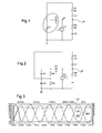
Fig. 1 shows a diagram of an electric circuit according to the invention, -
Fig. 2 shows a diagram of a preferred electric circuit according to the invention, and -
Fig. 3 shows a chart of detected voltages in the preferred electric circuit according to the invention. - According to
Fig. 1 an electric circuit comprises one power amplifier V1 for two piezoelectric actuators C1, C2. The two piezoelectric actuators C1, C2 are in antagonist arrangement connected mechanically in series. The two piezoelectric actuators C1, C2 are connected electrically with each other. The respective capacitances of the two piezoelectric actuators C1, C2 are at least approximately equal. The antagonist arrangement facilitates precompression of the piezoelectric actuators in order to prevent tensile stresses potentially leading to mechanical cracks of the piezoelectric material and enhances the reaction of the two piezoelectric actuators C1, C2 if they are both loaded the same way and reduces correspondingly the reaction of the two piezoelectric actuators C1, C2 if they are both loaded with opposed charges. - The two piezoelectric actuators C1, C2 are operated by a power amplifier V1 linked to a control circuit. The control circuit commands for time-variant, particularly a sinusoidal signal, energizing of the power amplifier V1 and subsequently the piezoelectric actuators C1, C2 in push-pull fashion.
- The power amplifier V1 is electrically connected to a junction point JP of the electrical connection between the two piezoelectric actuators C1, C2 and said power amplifier V1 is connected via a one directional diode D1 to at least one buffer capacitor C3 downstream the one directional diode D1 with regard to the power amplifier V1. The one directional diode D1 allows passage of electrical power from the power amplifier V1 and of fluctuating electrical power from the two piezoelectric actuators C1, C2 to charge the buffer capacitor C3. The buffer capacitor C3 discharges towards the two piezoelectric actuators C1, C2 switched in series with each other and the protection resistors R1, R2.
- The capacitance of the buffer capacitor C3 is >> than the respective capacitances of said two piezoelectric actuators C1, C2, i. e. C3 >> C1 or C2 with a factor of 10 ∼ 100 times. The protection resistors R1, R2 are provided with equally low resistance adapted to attenuate the speed of charging and discharging of said two piezoelectric actuators C1, C2 to avoid high electrical currents and high mechanical stress in said two piezoelectric actuators C1, C2.
- According to
Fig. 2 the same references are applied to corresponding features ofFig. 1 . The power amplifier V1 is electrically connected to the junction point JP of the electrical connection between the two piezoelectric actuators C1, C2 in series with each other and the protection resistors R1, R2 and the power amplifier V1 is connected to the one directional diode D1. Downstream the one directional diode D1 with regard to the power amplifier V1 are provided two static resistors R3, R4 connected electrically in series and connected electrically parallel with regard to the power amplifier V1. Downstream the one directional diode D1 with regard to the power amplifier V1 are as well provided two buffer capacitors C3, C4 connected electrically in series and connected electrically parallel with regard to the two static resistors R3, R4 for provision of a voltage divider. Said respective capacitances of said two buffer capacitors C3, C4 are approximately equal. The resistances of said two static resistors R3, R4 are approximately equal. - An electrical connection is provided from between the two static resistors R3, R4 to in between said two buffer capacitors C3, C4 towards said piezoelectric actuator C1 via the protection resistor R1.
- The approximately equal capacitances of said two buffer capacitors C3, C4 are >> than the respective capacitances of said two piezoelectric actuators C1, C2, i. e. C3, C4 >> C1 or C2 with a factor of 10 - 100 times. The protection resistors R1, R2 are provided with respective resistances << than the respectively approximately equal resistances of said two resistors R3, R4, i. e. a factor of 10 ∼ 100 times.
- According to
Fig. 3 the electric voltage at C1 is provided with small distortions subsequent to fluctuations of the voltages/currents at C3 and C4 caused by discharging and charging of the respective capacitances of said two piezoelectric actuators C1, C2 and most of all of said two buffer capacitors C3, C4. Said small distortions are shown with the minor deviations from linearity of the respective voltage graphs L3 and L4. The respective voltage graphs L3 and L4 at said buffer capacitors C3, C4 result from addition of two voltage modulation sequences M1, M2, phase shifted with regard to each other, for time-variant energizing of the piezoelectric actuators (C1, C2) at the frequency of actuation in the order of 7Hz to 35 Hz for four bladed rotors or up to 42Hz for five bladed rotors. - The alternating positive and negative voltages/currents of the two modulation sequences M1, M2 reflect the bipolar operation of the electric circuit.
-
- V1
- power amplifier
- C1
- piezoelectric actuator
- C2
- piezoelectric actuator
- JP
- junction point
- D1
- one directional diode
- C3
- buffer capacitor
- R1
- protection resistor
- R2
- protection resistor
- C4
- buffer capacitor
- R3
- static resistor
- R4
- static resistor
- L3
- buffer voltage graph
- L4
- buffer voltage graph
- M1
- modulation sequence
- M2
- modulation sequence
Claims (8)
- An electric circuit with one power amplifier (V1) for at least two piezoelectric actuators (C1, C2), said piezoelectric actuators (C1, C2) being in preferably antagonist arrangement connected mechanically in series and being connected electrically with each other and operated by the one power amplifier (V1) commanded by a control circuit for time-variant energizing of the piezoelectric actuators (C1, C2) in push-pull fashion, said power amplifier (V1) being connected to a junction point (JP) between the two piezoelectric actuators (C1, C2),
characterized in that said power amplifier (V1) is connected to a one directional diode (D1) and in that at least one buffer capacitor (C3) is provided downstream the one directional diode (D1) with regard to the power amplifier (V1). - The electric circuit according to claim 1,
characterized in that at least one protection resistor (R1) is provided between said one power amplifier (V1) and said at least two piezoelectric actuators (C1, C2). - The electric circuit according to claim 1,
characterized in that at least one further protection resistor (R2) is provided between said at least two piezoelectric actuators (C1, C2).. - The electric circuit according to claim 1,
characterized in that said power amplifier (V1) is based on pulse-width modulation (PWM). - The electric circuit according to claim 4,
characterized in that two static resistors (R4, R3) and two buffer capacitors (C3, C4) are provided respectively in series downstream the one directional diode (D1) with regard to the power amplifier (V1), said two static resistors (R4, R3) and two buffer capacitors (C3, C4) respectively in series being parallel to each other with a connection from between the two static resistors (R4, R3) to between the two buffer capacitors (C3, C4) and to said at least one protection resistor (R1) provided between said one power amplifier (V1) and said at least two piezoelectric actuators (C1, C2). - The electric circuit according to claim 1,
characterized in that the buffer capacitor (C3) is provided with a capacity >> than the capacities of said at least two piezoelectric actuators (C1, C2), i. e. a factor of 10 - 100 times, said capacities of said at least two piezoelectric actuators (C1, C2) being equal. - The electric circuit according to claim 1,
characterized in that the protection resistors (R1, R2) are provided with respective resistances << than the respective resistances of said two resistors (R3, R4), i. e. a factor of 10 ∼ 100 times. - An application of the electric circuit according to any of the preceding claims to helicopters, particularly to helicopter rotors with a frequency of actuation in the order of 7Hz (1/rev) to 35 Hz (5/rev) for four bladed or 42Hz (6/rev) for five bladed rotors.
Priority Applications (3)
| Application Number | Priority Date | Filing Date | Title |
|---|---|---|---|
| EP12400047.2A EP2733839B1 (en) | 2012-11-14 | 2012-11-14 | Electric circuit with one power amplifier for antagonistic piezoelectric actuators |
| CA2831245A CA2831245C (en) | 2012-11-14 | 2013-10-24 | Electric circuit with power amplifier for piezoelectric actuators |
| US14/067,148 US9484843B2 (en) | 2012-11-14 | 2013-10-30 | Electric circuit with power amplifier for piezoelectric actuators |
Applications Claiming Priority (1)
| Application Number | Priority Date | Filing Date | Title |
|---|---|---|---|
| EP12400047.2A EP2733839B1 (en) | 2012-11-14 | 2012-11-14 | Electric circuit with one power amplifier for antagonistic piezoelectric actuators |
Publications (2)
| Publication Number | Publication Date |
|---|---|
| EP2733839A1 true EP2733839A1 (en) | 2014-05-21 |
| EP2733839B1 EP2733839B1 (en) | 2017-01-04 |
Family
ID=47665846
Family Applications (1)
| Application Number | Title | Priority Date | Filing Date |
|---|---|---|---|
| EP12400047.2A Not-in-force EP2733839B1 (en) | 2012-11-14 | 2012-11-14 | Electric circuit with one power amplifier for antagonistic piezoelectric actuators |
Country Status (3)
| Country | Link |
|---|---|
| US (1) | US9484843B2 (en) |
| EP (1) | EP2733839B1 (en) |
| CA (1) | CA2831245C (en) |
Cited By (1)
| Publication number | Priority date | Publication date | Assignee | Title |
|---|---|---|---|---|
| DE102014110753A1 (en) | 2014-07-29 | 2016-02-04 | Airbus Defence and Space GmbH | Power generator with electronic component formed by inertial mass and drive circuit for this purpose |
Families Citing this family (3)
| Publication number | Priority date | Publication date | Assignee | Title |
|---|---|---|---|---|
| DE202012007128U1 (en) * | 2012-07-23 | 2012-08-02 | Robert Bosch Gmbh | Valve for metering fluid |
| US10086217B2 (en) | 2014-07-25 | 2018-10-02 | Covidien Lp | Electrosurgical ultrasonic vessel sealing and dissecting system |
| US12210294B2 (en) | 2019-05-20 | 2025-01-28 | Asml Netherlands B.V. | Actuator assemblies comprising piezo actuators or electrostrictive actuators |
Citations (6)
| Publication number | Priority date | Publication date | Assignee | Title |
|---|---|---|---|---|
| US6411009B2 (en) | 1999-12-17 | 2002-06-25 | Eads Deutschland Gmbh | Piezoelectric actuator system |
| DE10321705A1 (en) * | 2003-05-14 | 2004-12-02 | Marco Systemanalyse Und Entwicklung Gmbh | Piezoelectric drive element with several identical stacks of layers of piezoelectric material with electrodes, including electrical breakdown protection stack segments |
| US20050280332A1 (en) | 2004-06-11 | 2005-12-22 | Nokia Corporation | Driving ciruit for piezoelectric motor |
| US20050285477A1 (en) | 2004-06-11 | 2005-12-29 | Nokia Corporation | Energy saving driving circuit for piezoelectric motor |
| US20060267523A1 (en) * | 2003-01-20 | 2006-11-30 | Eurocopter Deutschland Gmbh | Device and method for transmitting and proving the energy of capacitive actuators |
| US20080316671A1 (en) | 2007-06-22 | 2008-12-25 | Denso Corporation | Piezoelectric actuator driving device and method |
Family Cites Families (5)
| Publication number | Priority date | Publication date | Assignee | Title |
|---|---|---|---|---|
| US3963372A (en) | 1975-01-17 | 1976-06-15 | General Motors Corporation | Helicopter power plant control |
| JP3804312B2 (en) * | 1998-12-17 | 2006-08-02 | コニカミノルタホールディングス株式会社 | Piezoelectric actuator and piezoelectric actuator driving device |
| US9355571B2 (en) | 2008-01-23 | 2016-05-31 | Sikorsky Aircraft Corporation | Modules and methods for biasing power to a multi-engine power plant suitable for one engine inoperative flight procedure training |
| JP2009178926A (en) * | 2008-01-30 | 2009-08-13 | Seiko Epson Corp | Capacitive load drive circuit and liquid ejection device |
| FR2933910B1 (en) | 2008-07-18 | 2010-12-17 | Eurocopter France | HYBRID POWER PLANT AND METHOD FOR CONTROLLING SUCH A MOTOR INSTALLATION |
-
2012
- 2012-11-14 EP EP12400047.2A patent/EP2733839B1/en not_active Not-in-force
-
2013
- 2013-10-24 CA CA2831245A patent/CA2831245C/en not_active Expired - Fee Related
- 2013-10-30 US US14/067,148 patent/US9484843B2/en not_active Expired - Fee Related
Patent Citations (6)
| Publication number | Priority date | Publication date | Assignee | Title |
|---|---|---|---|---|
| US6411009B2 (en) | 1999-12-17 | 2002-06-25 | Eads Deutschland Gmbh | Piezoelectric actuator system |
| US20060267523A1 (en) * | 2003-01-20 | 2006-11-30 | Eurocopter Deutschland Gmbh | Device and method for transmitting and proving the energy of capacitive actuators |
| DE10321705A1 (en) * | 2003-05-14 | 2004-12-02 | Marco Systemanalyse Und Entwicklung Gmbh | Piezoelectric drive element with several identical stacks of layers of piezoelectric material with electrodes, including electrical breakdown protection stack segments |
| US20050280332A1 (en) | 2004-06-11 | 2005-12-22 | Nokia Corporation | Driving ciruit for piezoelectric motor |
| US20050285477A1 (en) | 2004-06-11 | 2005-12-29 | Nokia Corporation | Energy saving driving circuit for piezoelectric motor |
| US20080316671A1 (en) | 2007-06-22 | 2008-12-25 | Denso Corporation | Piezoelectric actuator driving device and method |
Non-Patent Citations (1)
| Title |
|---|
| BILGEN O ET AL: "Lightweight high voltage electronic circuits for piezoelectric composite actuators", JOURNAL OF INTELLIGENT MATERIAL SYSTEMS AND STRUCTURES, vol. 21, no. 14, September 2010 (2010-09-01), pages 1417 - 1426, XP009168242, ISSN: 1045-389X * |
Cited By (3)
| Publication number | Priority date | Publication date | Assignee | Title |
|---|---|---|---|---|
| DE102014110753A1 (en) | 2014-07-29 | 2016-02-04 | Airbus Defence and Space GmbH | Power generator with electronic component formed by inertial mass and drive circuit for this purpose |
| EP2993372A1 (en) | 2014-07-29 | 2016-03-09 | Airbus Defence and Space GmbH | Force generator with inertial mass formed by an electronic component and drive circuit for same |
| US9673375B2 (en) | 2014-07-29 | 2017-06-06 | Airbus Defence and Space GmbH | Power generator with an electrical component made from inertial mass and control circuit thereof |
Also Published As
| Publication number | Publication date |
|---|---|
| US9484843B2 (en) | 2016-11-01 |
| CA2831245C (en) | 2016-03-29 |
| US20140132113A1 (en) | 2014-05-15 |
| EP2733839B1 (en) | 2017-01-04 |
| CA2831245A1 (en) | 2014-05-14 |
Similar Documents
| Publication | Publication Date | Title |
|---|---|---|
| EP2413450A2 (en) | Electric power generating and distribution system comprising a decoupling filter and a solid state power controller | |
| EP2733839B1 (en) | Electric circuit with one power amplifier for antagonistic piezoelectric actuators | |
| US11496059B2 (en) | Variable voltage generator circuit, capacitor and method | |
| CN102859829A (en) | Battery with variable output voltage | |
| JP2018074709A (en) | Power unit and metho for controlling power unit | |
| TW201436450A (en) | AC motor driving system | |
| US10284083B2 (en) | DC/DC converter with a flying capacitor | |
| CN104518660A (en) | Directly amplified ripple tracking control scheme for multiphase dc-dc converter | |
| CN109256945A (en) | For providing the PWM control program of minimum ON time | |
| US20180106245A1 (en) | Driving system for piezoelectric pump | |
| US8040017B2 (en) | Piezoelectric actuator | |
| CN117716628A (en) | Active discharge of vehicle intermediate circuit elements using discrete PWM pulse generation discharge circuits | |
| EP2693626A1 (en) | Inverter for driving motor | |
| WO2003103126A1 (en) | Power converter | |
| JP6429040B2 (en) | Drive circuit applied to piezoelectric drive pump | |
| CN205283427U (en) | Drive circuit and piezo-actuated pump for which it is applied | |
| Canacsinh et al. | Voltage droop compensation based on resonant circuit for generalized high voltage solid-state Marx modulator | |
| CN104821740A (en) | Travelling wave motor pre-driver using high resolution PWM generators | |
| JPWO2019130754A1 (en) | Pump device | |
| DE102011108175A1 (en) | Driving circuit for ultrasonic motor e.g. piezoelectric ultrasonic motor, has control unit that is adapted to direct current (DC) converter and inverters, to control measured amount of current flowing through ultrasonic motor | |
| US11355691B2 (en) | Piezoelectric actuator type control device for capacitive loads | |
| Kumar et al. | Hybrid quasi-Z-source dc-dc boost converter | |
| CN209844858U (en) | Amplitude stabilizing control circuit for ultrasonic motor | |
| EP4047803A1 (en) | High-frequency current source for an active emi filter, active emi filter and use of an active emi filter | |
| CN106936332B (en) | Driving circuit and piezoelectric actuating pump suitable for same |
Legal Events
| Date | Code | Title | Description |
|---|---|---|---|
| PUAI | Public reference made under article 153(3) epc to a published international application that has entered the european phase |
Free format text: ORIGINAL CODE: 0009012 |
|
| 17P | Request for examination filed |
Effective date: 20121114 |
|
| AK | Designated contracting states |
Kind code of ref document: A1 Designated state(s): AL AT BE BG CH CY CZ DE DK EE ES FI FR GB GR HR HU IE IS IT LI LT LU LV MC MK MT NL NO PL PT RO RS SE SI SK SM TR |
|
| AX | Request for extension of the european patent |
Extension state: BA ME |
|
| R17P | Request for examination filed (corrected) |
Effective date: 20140605 |
|
| RBV | Designated contracting states (corrected) |
Designated state(s): AL AT BE BG CH CY CZ DE DK EE ES FI FR GB GR HR HU IE IS IT LI LT LU LV MC MK MT NL NO PL PT RO RS SE SI SK SM TR |
|
| RAP1 | Party data changed (applicant data changed or rights of an application transferred) |
Owner name: AIRBUS HELICOPTERS DEUTSCHLAND GMBH Owner name: AIRBUS DEFENCE AND SPACE GMBH |
|
| GRAP | Despatch of communication of intention to grant a patent |
Free format text: ORIGINAL CODE: EPIDOSNIGR1 |
|
| INTG | Intention to grant announced |
Effective date: 20160712 |
|
| GRAS | Grant fee paid |
Free format text: ORIGINAL CODE: EPIDOSNIGR3 |
|
| GRAA | (expected) grant |
Free format text: ORIGINAL CODE: 0009210 |
|
| AK | Designated contracting states |
Kind code of ref document: B1 Designated state(s): AL AT BE BG CH CY CZ DE DK EE ES FI FR GB GR HR HU IE IS IT LI LT LU LV MC MK MT NL NO PL PT RO RS SE SI SK SM TR |
|
| REG | Reference to a national code |
Ref country code: GB Ref legal event code: FG4D |
|
| REG | Reference to a national code |
Ref country code: CH Ref legal event code: EP |
|
| REG | Reference to a national code |
Ref country code: AT Ref legal event code: REF Ref document number: 860133 Country of ref document: AT Kind code of ref document: T Effective date: 20170115 |
|
| REG | Reference to a national code |
Ref country code: IE Ref legal event code: FG4D |
|
| REG | Reference to a national code |
Ref country code: DE Ref legal event code: R096 Ref document number: 602012027338 Country of ref document: DE |
|
| REG | Reference to a national code |
Ref country code: LT Ref legal event code: MG4D Ref country code: NL Ref legal event code: MP Effective date: 20170104 |
|
| REG | Reference to a national code |
Ref country code: AT Ref legal event code: MK05 Ref document number: 860133 Country of ref document: AT Kind code of ref document: T Effective date: 20170104 |
|
| PG25 | Lapsed in a contracting state [announced via postgrant information from national office to epo] |
Ref country code: NL Free format text: LAPSE BECAUSE OF FAILURE TO SUBMIT A TRANSLATION OF THE DESCRIPTION OR TO PAY THE FEE WITHIN THE PRESCRIBED TIME-LIMIT Effective date: 20170104 |
|
| PG25 | Lapsed in a contracting state [announced via postgrant information from national office to epo] |
Ref country code: FI Free format text: LAPSE BECAUSE OF FAILURE TO SUBMIT A TRANSLATION OF THE DESCRIPTION OR TO PAY THE FEE WITHIN THE PRESCRIBED TIME-LIMIT Effective date: 20170104 Ref country code: NO Free format text: LAPSE BECAUSE OF FAILURE TO SUBMIT A TRANSLATION OF THE DESCRIPTION OR TO PAY THE FEE WITHIN THE PRESCRIBED TIME-LIMIT Effective date: 20170404 Ref country code: HR Free format text: LAPSE BECAUSE OF FAILURE TO SUBMIT A TRANSLATION OF THE DESCRIPTION OR TO PAY THE FEE WITHIN THE PRESCRIBED TIME-LIMIT Effective date: 20170104 Ref country code: LT Free format text: LAPSE BECAUSE OF FAILURE TO SUBMIT A TRANSLATION OF THE DESCRIPTION OR TO PAY THE FEE WITHIN THE PRESCRIBED TIME-LIMIT Effective date: 20170104 Ref country code: IS Free format text: LAPSE BECAUSE OF FAILURE TO SUBMIT A TRANSLATION OF THE DESCRIPTION OR TO PAY THE FEE WITHIN THE PRESCRIBED TIME-LIMIT Effective date: 20170504 Ref country code: GR Free format text: LAPSE BECAUSE OF FAILURE TO SUBMIT A TRANSLATION OF THE DESCRIPTION OR TO PAY THE FEE WITHIN THE PRESCRIBED TIME-LIMIT Effective date: 20170405 |
|
| PG25 | Lapsed in a contracting state [announced via postgrant information from national office to epo] |
Ref country code: LV Free format text: LAPSE BECAUSE OF FAILURE TO SUBMIT A TRANSLATION OF THE DESCRIPTION OR TO PAY THE FEE WITHIN THE PRESCRIBED TIME-LIMIT Effective date: 20170104 Ref country code: RS Free format text: LAPSE BECAUSE OF FAILURE TO SUBMIT A TRANSLATION OF THE DESCRIPTION OR TO PAY THE FEE WITHIN THE PRESCRIBED TIME-LIMIT Effective date: 20170104 Ref country code: SE Free format text: LAPSE BECAUSE OF FAILURE TO SUBMIT A TRANSLATION OF THE DESCRIPTION OR TO PAY THE FEE WITHIN THE PRESCRIBED TIME-LIMIT Effective date: 20170104 Ref country code: ES Free format text: LAPSE BECAUSE OF FAILURE TO SUBMIT A TRANSLATION OF THE DESCRIPTION OR TO PAY THE FEE WITHIN THE PRESCRIBED TIME-LIMIT Effective date: 20170104 Ref country code: BG Free format text: LAPSE BECAUSE OF FAILURE TO SUBMIT A TRANSLATION OF THE DESCRIPTION OR TO PAY THE FEE WITHIN THE PRESCRIBED TIME-LIMIT Effective date: 20170404 Ref country code: PT Free format text: LAPSE BECAUSE OF FAILURE TO SUBMIT A TRANSLATION OF THE DESCRIPTION OR TO PAY THE FEE WITHIN THE PRESCRIBED TIME-LIMIT Effective date: 20170504 Ref country code: PL Free format text: LAPSE BECAUSE OF FAILURE TO SUBMIT A TRANSLATION OF THE DESCRIPTION OR TO PAY THE FEE WITHIN THE PRESCRIBED TIME-LIMIT Effective date: 20170104 Ref country code: AT Free format text: LAPSE BECAUSE OF FAILURE TO SUBMIT A TRANSLATION OF THE DESCRIPTION OR TO PAY THE FEE WITHIN THE PRESCRIBED TIME-LIMIT Effective date: 20170104 |
|
| REG | Reference to a national code |
Ref country code: DE Ref legal event code: R097 Ref document number: 602012027338 Country of ref document: DE |
|
| PG25 | Lapsed in a contracting state [announced via postgrant information from national office to epo] |
Ref country code: SK Free format text: LAPSE BECAUSE OF FAILURE TO SUBMIT A TRANSLATION OF THE DESCRIPTION OR TO PAY THE FEE WITHIN THE PRESCRIBED TIME-LIMIT Effective date: 20170104 Ref country code: EE Free format text: LAPSE BECAUSE OF FAILURE TO SUBMIT A TRANSLATION OF THE DESCRIPTION OR TO PAY THE FEE WITHIN THE PRESCRIBED TIME-LIMIT Effective date: 20170104 Ref country code: RO Free format text: LAPSE BECAUSE OF FAILURE TO SUBMIT A TRANSLATION OF THE DESCRIPTION OR TO PAY THE FEE WITHIN THE PRESCRIBED TIME-LIMIT Effective date: 20170104 Ref country code: CZ Free format text: LAPSE BECAUSE OF FAILURE TO SUBMIT A TRANSLATION OF THE DESCRIPTION OR TO PAY THE FEE WITHIN THE PRESCRIBED TIME-LIMIT Effective date: 20170104 |
|
| PLBE | No opposition filed within time limit |
Free format text: ORIGINAL CODE: 0009261 |
|
| STAA | Information on the status of an ep patent application or granted ep patent |
Free format text: STATUS: NO OPPOSITION FILED WITHIN TIME LIMIT |
|
| REG | Reference to a national code |
Ref country code: FR Ref legal event code: PLFP Year of fee payment: 6 |
|
| PG25 | Lapsed in a contracting state [announced via postgrant information from national office to epo] |
Ref country code: SM Free format text: LAPSE BECAUSE OF FAILURE TO SUBMIT A TRANSLATION OF THE DESCRIPTION OR TO PAY THE FEE WITHIN THE PRESCRIBED TIME-LIMIT Effective date: 20170104 Ref country code: DK Free format text: LAPSE BECAUSE OF FAILURE TO SUBMIT A TRANSLATION OF THE DESCRIPTION OR TO PAY THE FEE WITHIN THE PRESCRIBED TIME-LIMIT Effective date: 20170104 |
|
| 26N | No opposition filed |
Effective date: 20171005 |
|
| PG25 | Lapsed in a contracting state [announced via postgrant information from national office to epo] |
Ref country code: SI Free format text: LAPSE BECAUSE OF FAILURE TO SUBMIT A TRANSLATION OF THE DESCRIPTION OR TO PAY THE FEE WITHIN THE PRESCRIBED TIME-LIMIT Effective date: 20170104 |
|
| PG25 | Lapsed in a contracting state [announced via postgrant information from national office to epo] |
Ref country code: MC Free format text: LAPSE BECAUSE OF FAILURE TO SUBMIT A TRANSLATION OF THE DESCRIPTION OR TO PAY THE FEE WITHIN THE PRESCRIBED TIME-LIMIT Effective date: 20170104 |
|
| PG25 | Lapsed in a contracting state [announced via postgrant information from national office to epo] |
Ref country code: CH Free format text: LAPSE BECAUSE OF NON-PAYMENT OF DUE FEES Effective date: 20171130 Ref country code: LI Free format text: LAPSE BECAUSE OF NON-PAYMENT OF DUE FEES Effective date: 20171130 |
|
| PG25 | Lapsed in a contracting state [announced via postgrant information from national office to epo] |
Ref country code: LU Free format text: LAPSE BECAUSE OF NON-PAYMENT OF DUE FEES Effective date: 20171114 |
|
| REG | Reference to a national code |
Ref country code: BE Ref legal event code: MM Effective date: 20171130 |
|
| REG | Reference to a national code |
Ref country code: IE Ref legal event code: MM4A |
|
| PG25 | Lapsed in a contracting state [announced via postgrant information from national office to epo] |
Ref country code: MT Free format text: LAPSE BECAUSE OF NON-PAYMENT OF DUE FEES Effective date: 20171114 |
|
| PG25 | Lapsed in a contracting state [announced via postgrant information from national office to epo] |
Ref country code: IE Free format text: LAPSE BECAUSE OF NON-PAYMENT OF DUE FEES Effective date: 20171114 |
|
| PG25 | Lapsed in a contracting state [announced via postgrant information from national office to epo] |
Ref country code: BE Free format text: LAPSE BECAUSE OF NON-PAYMENT OF DUE FEES Effective date: 20171130 |
|
| PG25 | Lapsed in a contracting state [announced via postgrant information from national office to epo] |
Ref country code: HU Free format text: LAPSE BECAUSE OF FAILURE TO SUBMIT A TRANSLATION OF THE DESCRIPTION OR TO PAY THE FEE WITHIN THE PRESCRIBED TIME-LIMIT; INVALID AB INITIO Effective date: 20121114 |
|
| PG25 | Lapsed in a contracting state [announced via postgrant information from national office to epo] |
Ref country code: CY Free format text: LAPSE BECAUSE OF NON-PAYMENT OF DUE FEES Effective date: 20170104 |
|
| PG25 | Lapsed in a contracting state [announced via postgrant information from national office to epo] |
Ref country code: MK Free format text: LAPSE BECAUSE OF FAILURE TO SUBMIT A TRANSLATION OF THE DESCRIPTION OR TO PAY THE FEE WITHIN THE PRESCRIBED TIME-LIMIT Effective date: 20170104 |
|
| PGFP | Annual fee paid to national office [announced via postgrant information from national office to epo] |
Ref country code: DE Payment date: 20191121 Year of fee payment: 8 |
|
| PGFP | Annual fee paid to national office [announced via postgrant information from national office to epo] |
Ref country code: FR Payment date: 20191120 Year of fee payment: 8 Ref country code: IT Payment date: 20191128 Year of fee payment: 8 |
|
| PG25 | Lapsed in a contracting state [announced via postgrant information from national office to epo] |
Ref country code: TR Free format text: LAPSE BECAUSE OF FAILURE TO SUBMIT A TRANSLATION OF THE DESCRIPTION OR TO PAY THE FEE WITHIN THE PRESCRIBED TIME-LIMIT Effective date: 20170104 |
|
| PGFP | Annual fee paid to national office [announced via postgrant information from national office to epo] |
Ref country code: GB Payment date: 20191120 Year of fee payment: 8 |
|
| PG25 | Lapsed in a contracting state [announced via postgrant information from national office to epo] |
Ref country code: AL Free format text: LAPSE BECAUSE OF FAILURE TO SUBMIT A TRANSLATION OF THE DESCRIPTION OR TO PAY THE FEE WITHIN THE PRESCRIBED TIME-LIMIT Effective date: 20170104 |
|
| REG | Reference to a national code |
Ref country code: DE Ref legal event code: R119 Ref document number: 602012027338 Country of ref document: DE |
|
| GBPC | Gb: european patent ceased through non-payment of renewal fee |
Effective date: 20201114 |
|
| PG25 | Lapsed in a contracting state [announced via postgrant information from national office to epo] |
Ref country code: IT Free format text: LAPSE BECAUSE OF NON-PAYMENT OF DUE FEES Effective date: 20201114 Ref country code: FR Free format text: LAPSE BECAUSE OF NON-PAYMENT OF DUE FEES Effective date: 20201130 |
|
| PG25 | Lapsed in a contracting state [announced via postgrant information from national office to epo] |
Ref country code: DE Free format text: LAPSE BECAUSE OF NON-PAYMENT OF DUE FEES Effective date: 20210601 Ref country code: GB Free format text: LAPSE BECAUSE OF NON-PAYMENT OF DUE FEES Effective date: 20201114 |