EP2733702A1 - System and method for classifying media defects based on a ratio of harmonics - Google Patents
System and method for classifying media defects based on a ratio of harmonics Download PDFInfo
- Publication number
- EP2733702A1 EP2733702A1 EP13189246.5A EP13189246A EP2733702A1 EP 2733702 A1 EP2733702 A1 EP 2733702A1 EP 13189246 A EP13189246 A EP 13189246A EP 2733702 A1 EP2733702 A1 EP 2733702A1
- Authority
- EP
- European Patent Office
- Prior art keywords
- defect
- waveform
- harmonics
- ratio
- classifying
- Prior art date
- Legal status (The legal status is an assumption and is not a legal conclusion. Google has not performed a legal analysis and makes no representation as to the accuracy of the status listed.)
- Withdrawn
Links
Images



Classifications
-
- G—PHYSICS
- G11—INFORMATION STORAGE
- G11B—INFORMATION STORAGE BASED ON RELATIVE MOVEMENT BETWEEN RECORD CARRIER AND TRANSDUCER
- G11B27/00—Editing; Indexing; Addressing; Timing or synchronising; Monitoring; Measuring tape travel
- G11B27/36—Monitoring, i.e. supervising the progress of recording or reproducing
-
- G—PHYSICS
- G01—MEASURING; TESTING
- G01R—MEASURING ELECTRIC VARIABLES; MEASURING MAGNETIC VARIABLES
- G01R23/00—Arrangements for measuring frequencies; Arrangements for analysing frequency spectra
- G01R23/02—Arrangements for measuring frequency, e.g. pulse repetition rate; Arrangements for measuring period of current or voltage
-
- G—PHYSICS
- G01—MEASURING; TESTING
- G01R—MEASURING ELECTRIC VARIABLES; MEASURING MAGNETIC VARIABLES
- G01R31/00—Arrangements for testing electric properties; Arrangements for locating electric faults; Arrangements for electrical testing characterised by what is being tested not provided for elsewhere
- G01R31/28—Testing of electronic circuits, e.g. by signal tracer
- G01R31/317—Testing of digital circuits
- G01R31/3181—Functional testing
- G01R31/3183—Generation of test inputs, e.g. test vectors, patterns or sequences
-
- G—PHYSICS
- G11—INFORMATION STORAGE
- G11B—INFORMATION STORAGE BASED ON RELATIVE MOVEMENT BETWEEN RECORD CARRIER AND TRANSDUCER
- G11B20/00—Signal processing not specific to the method of recording or reproducing; Circuits therefor
- G11B20/10—Digital recording or reproducing
- G11B20/18—Error detection or correction; Testing, e.g. of drop-outs
- G11B20/1816—Testing
- G11B20/182—Testing using test patterns
-
- G—PHYSICS
- G11—INFORMATION STORAGE
- G11B—INFORMATION STORAGE BASED ON RELATIVE MOVEMENT BETWEEN RECORD CARRIER AND TRANSDUCER
- G11B2220/00—Record carriers by type
- G11B2220/20—Disc-shaped record carriers
- G11B2220/25—Disc-shaped record carriers characterised in that the disc is based on a specific recording technology
- G11B2220/2508—Magnetic discs
- G11B2220/2516—Hard disks
Definitions
- Data can be stored on several types of carrier media, such as hard disk drives, optical disks, and other forms of permanent or semi-permanent storage. Defects in carrier media result in unreliable behavior, poor performance, or data corruption. Testing for media defects can improve reliability in data storage systems.
- An embodiment of the disclosure is a method of detecting and classifying at least one media defect.
- a periodic pattern is written to a medium to yield at least one waveform.
- the magnitude of the waveform is compared against a defect threshold to detect the presence or absence of media defects in the medium.
- a magnitude for each of at least two harmonics of the waveform is determined in the defect range. The magnitudes of the at least two harmonics are utilized to classify the defect.
- FIGS. 1A through 3 illustrate embodiments of a system and method for detecting and classifying at least one media defect.
- Defects including, but not limited to, thermal asperity (TA) and delaminated (DLM) defects are known to occur in carrier media such as hard disk drives and other permanent or semi-permanent storage devices.
- carrier media such as hard disk drives and other permanent or semi-permanent storage devices.
- test medium is used throughout the disclosure to reference any carrier medium being operated upon by a system or method embodied herein.
- FIG. 1A illustrates an embodiment of a system 100 for detecting and classifying at least one defect of at least one test medium 102.
- the system 100 includes a computing system 104 in communication with the test medium 102.
- the computing system 104 includes any combination of hardware, software, or firmware configured for executing one or more steps described herein for detecting and classifying at least one defect of the test medium 102.
- the computing system 104 includes at least one processor 106 configured for executing program instructions 110 from carrier media 108 to complete one or more of the steps described herein.
- the computing system 104 includes an electronic circuit configured for completing one or more of the steps described herein.
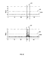
- the computing system 104 is configured for writing a periodic pattern to the test medium 102 to generate a waveform 120, as illustrated in FIG. 1 B .
- the periodic pattern includes, but is not limited to, a 4T pattern.
- the computing system 104 is further configured for comparing the waveform 102 to a defect threshold to determine the presence or absence of media defects.
- the defect threshold is a selected value or a predetermined value.
- the defect threshold is related to the type of test medium 102.
- the computing system 104 detects at least one defect when a magnitude of the waveform 120 is below the defect threshold.
- a defect range 122 includes a portion of the waveform 120 affected by the defect, such as an attenuated portion of the waveform 120 or a portion of the waveform 120 having lower amplitude than the remainder of the waveform 120.
- the computing system 104 is further configured for classifying the detected defect utilizing at least two harmonics of the waveform 120.
- the two harmonics include, but are not limited to, a first harmonic and a third harmonic of the waveform 120.
- a harmonic is a component of the waveform 120 that has a frequency that is an integer multiple of the fundamental frequency. Accordingly, the first harmonic is a component of the waveform 120 at the fundamental frequency and the third harmonic is a component of the waveform 120 at three times the fundamental frequency, and so on.
- the computing system 104 is configured for determining a magnitude of each harmonic over the defect range 122.
- the computing system 104 is further configured for determining a ratio 124 of the magnitudes of the two harmonics.
- the computing system 104 is configured comparing the ratio 124 to a classification threshold 126 to classifying the detected defect.
- the classification threshold is a selected or predetermined value. In some embodiments, the classification threshold is related to the type of test medium 102.
- the computing system is configured to classify the detected defect as a TA defect or a DLM defect based on whether the ratio 124 is less than or not less than the classification threshold 126. Classifying the defect utilizing the ratio 124 of the magnitudes of the two harmonics provides reliability advantages under high density and low SNR conditions.
- the computing system 104 is configured to determine the ratio 124 of the magnitude of the third harmonic of the waveform 120 over the magnitude of the first harmonic of the waveform 120.
- the computing system 104 is configured to classify the defect as a TA defect when the ratio 124A is less than the classification threshold 126.
- the computing system 104 is further configured to classify the defect as a DLM defect when the ratio 124B is not less than the classification threshold 126.
- f n is a magnitude of the n th harmonic and x 4T is the read back 4T waveform at time instant k.
- FIG. 2 illustrates an embodiment of a method 200 of detecting and classifying at least one defect of the test medium 102.
- method 200 is executed by one or more elements of system 100.
- system 100 should not be construed as limitations on method 200. It is contemplated that one or more of the following steps of method 200 can be executed by additional systems or devices known to the art.
- a periodic pattern is written to the test medium 102 to yield at least one waveform 120.
- the periodic pattern includes a 4T pattern.
- a magnitude of the waveform 120 is compared against a defect threshold to determine the presence or absence of a defect.
- a defect is detected when the magnitude of the waveform 120 is less than the defect threshold.
- magnitudes of at least two harmonics of the waveform 120 are determined over the defect range 122.
- the two harmonics include a first harmonic of the waveform and a third harmonic of the wave form.
- the defect is classified utilizing the magnitudes of the two harmonics.
- a ratio 124 of the two harmonics is compared against a classification threshold 126 to determine the defect type.
- the defect is classified as either a TA defect or a DLM defect based on whether the ratio 124 is less than the defect threshold 126 or not less than the defect threshold 126.
- FIG. 3 Another embodiment of a method 300 for detecting and classifying at least one media defect is illustrated in FIG. 3 . Any of the foregoing embodiments of method 200 similarly apply to method 300 unless otherwise noted.
- method 300 is executed by one or more elements of system 100. However, the foregoing embodiments of system 100 or method 200 should not be construed as limitations on method 300. It is contemplated that one or more of the following steps of method 300 can be executed by additional systems or devices known to the art.
- a periodic pattern is written to the test medium 102 to yield at least one waveform 120.
- a magnitude of the waveform 120 is compared against a defect threshold to determine the presence or absence of a defect. At least one defect is detected when the magnitude of the waveform 120 is less than the defect threshold.
- magnitudes of at least two harmonics of the waveform 120 are determined over the defect range 122.
- a ratio 124 of the magnitudes of the two harmonics is determined.
- the defect is classified by comparing the ratio 124 of the magnitudes of the two harmonics and a classification threshold 126 to determine the defect type.
- the defect is classified as either a TA defect when the ratio 124A is less than the classification threshold 126 (i.e. ratio ⁇ ClassT).
- the defect is alternatively classified as a DLM defect when the ratio 124B is not less than the defect threshold 126 (i.e. ratio ⁇ ClassT).
- a computing system may include, but is not limited to, a personal computing system, mainframe computing system, workstation, image computer, parallel processor, or any other device known in the art.
- the term "computing system” is broadly defined to encompass any device having one or more processors, which execute instructions from a memory medium.
- the carrier medium may be a transmission medium, such as, but not limited to, a wire, cable, or wireless transmission link.
- the carrier medium may also include a storage medium such as, but not limited to, a read-only memory, a random access memory, a magnetic or optical disk, or a magnetic tape.
- Embodiments manifesting methods described herein may include storing results in a storage medium. After the results have been stored, the results can be accessed in the storage medium and used by any of the method or system embodiments described herein, formatted for display to a user, used by another software module, method, or system, etc. Furthermore, the results may be stored "permanently,” “semi-permanently,” temporarily, or for some period of time.
- the storage medium may be random access memory (RAM), and the results may not necessarily persist indefinitely in the storage medium.
- any embodiment of the disclosure manifested above as a system or method may include at least a portion of any other embodiment described herein.
- Those having skill in the art will appreciate that there are various embodiments by which systems and methods described herein can be effected, and that the implementation will vary with the context in which an embodiment of the disclosure deployed.
Landscapes
- Engineering & Computer Science (AREA)
- Signal Processing (AREA)
- Physics & Mathematics (AREA)
- General Physics & Mathematics (AREA)
- General Engineering & Computer Science (AREA)
- Optical Recording Or Reproduction (AREA)
- Signal Processing For Digital Recording And Reproducing (AREA)
- Recording Or Reproducing By Magnetic Means (AREA)
- Manufacturing Of Magnetic Record Carriers (AREA)
- Investigating Materials By The Use Of Optical Means Adapted For Particular Applications (AREA)
- Investigating Or Analyzing Materials By The Use Of Ultrasonic Waves (AREA)
Abstract
Description
- Data can be stored on several types of carrier media, such as hard disk drives, optical disks, and other forms of permanent or semi-permanent storage. Defects in carrier media result in unreliable behavior, poor performance, or data corruption. Testing for media defects can improve reliability in data storage systems.
- An embodiment of the disclosure is a method of detecting and classifying at least one media defect. A periodic pattern is written to a medium to yield at least one waveform. The magnitude of the waveform is compared against a defect threshold to detect the presence or absence of media defects in the medium. When at least one defect is detected, a magnitude for each of at least two harmonics of the waveform is determined in the defect range. The magnitudes of the at least two harmonics are utilized to classify the defect.
- It is to be understood that both the foregoing general description and the following detailed description are not necessarily restrictive of the disclosure. The accompanying drawings, which are incorporated in and constitute a part of the specification, illustrate embodiments of the disclosure.
- The embodiments of the disclosure may be better understood by those skilled in the art by reference to the accompanying figures in which:
- FIG. 1A
- is a block diagram illustrating a system for detecting and classifying at least one media defect, in accordance with an embodiment of the disclosure;
- FIG. 1B
- is a graphical illustration of a waveform generated by writing a periodic pattern to a medium, in accordance with an embodiment of the disclosure;
- FIG. 1C
- is a graphical illustration of a ratio of magnitudes of at least two harmonics of the at least one waveform compared to a classification threshold, in accordance with an embodiment of the disclosure;
- FIG. 2
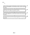
- is a flow diagram illustrating a method of detecting and classifying at least one media defect, in accordance with an embodiment of the disclosure; and
- FIG. 3
- is a flow diagram illustrating a method of detecting and classifying at least one media defect, in accordance with an embodiment of the disclosure.
- Reference will now be made in detail to the embodiments disclosed, which are illustrated in the accompanying drawings.
-
FIGS. 1A through 3 illustrate embodiments of a system and method for detecting and classifying at least one media defect. Defects including, but not limited to, thermal asperity (TA) and delaminated (DLM) defects are known to occur in carrier media such as hard disk drives and other permanent or semi-permanent storage devices. The term "test medium" is used throughout the disclosure to reference any carrier medium being operated upon by a system or method embodied herein. -
FIG. 1A illustrates an embodiment of asystem 100 for detecting and classifying at least one defect of at least onetest medium 102. Thesystem 100 includes acomputing system 104 in communication with thetest medium 102. Thecomputing system 104 includes any combination of hardware, software, or firmware configured for executing one or more steps described herein for detecting and classifying at least one defect of thetest medium 102. In an embodiment, thecomputing system 104 includes at least oneprocessor 106 configured for executingprogram instructions 110 fromcarrier media 108 to complete one or more of the steps described herein. In another embodiment, thecomputing system 104 includes an electronic circuit configured for completing one or more of the steps described herein. - The
computing system 104 is configured for writing a periodic pattern to thetest medium 102 to generate awaveform 120, as illustrated inFIG. 1 B . In some embodiments, the periodic pattern includes, but is not limited to, a 4T pattern. Thecomputing system 104 is further configured for comparing thewaveform 102 to a defect threshold to determine the presence or absence of media defects. The defect threshold is a selected value or a predetermined value. In some embodiments, the defect threshold is related to the type oftest medium 102. In an embodiment, thecomputing system 104 detects at least one defect when a magnitude of thewaveform 120 is below the defect threshold. Adefect range 122 includes a portion of thewaveform 120 affected by the defect, such as an attenuated portion of thewaveform 120 or a portion of thewaveform 120 having lower amplitude than the remainder of thewaveform 120. - The
computing system 104 is further configured for classifying the detected defect utilizing at least two harmonics of thewaveform 120. In some embodiments, the two harmonics include, but are not limited to, a first harmonic and a third harmonic of thewaveform 120. A harmonic is a component of thewaveform 120 that has a frequency that is an integer multiple of the fundamental frequency. Accordingly, the first harmonic is a component of thewaveform 120 at the fundamental frequency and the third harmonic is a component of thewaveform 120 at three times the fundamental frequency, and so on. - The
computing system 104 is configured for determining a magnitude of each harmonic over thedefect range 122. Thecomputing system 104 is further configured for determining a ratio 124 of the magnitudes of the two harmonics. As illustrated inFIG. 1 C , thecomputing system 104 is configured comparing the ratio 124 to aclassification threshold 126 to classifying the detected defect. The classification threshold is a selected or predetermined value. In some embodiments, the classification threshold is related to the type oftest medium 102. In some embodiments, the computing system is configured to classify the detected defect as a TA defect or a DLM defect based on whether the ratio 124 is less than or not less than theclassification threshold 126. Classifying the defect utilizing the ratio 124 of the magnitudes of the two harmonics provides reliability advantages under high density and low SNR conditions. - In an embodiment, the
computing system 104 is configured to determine the ratio 124 of the magnitude of the third harmonic of thewaveform 120 over the magnitude of the first harmonic of thewaveform 120. Thecomputing system 104 is configured to classify the defect as a TA defect when theratio 124A is less than theclassification threshold 126. Thecomputing system 104 is further configured to classify the defect as a DLM defect when theratio 124B is not less than theclassification threshold 126. - In another embodiment, the magnitude of the first harmonic and the third harmonic are determined in accordance with the following equation:

-
FIG. 2 illustrates an embodiment of amethod 200 of detecting and classifying at least one defect of thetest medium 102. In some embodiments,method 200 is executed by one or more elements ofsystem 100. However, the foregoing embodiments ofsystem 100 should not be construed as limitations onmethod 200. It is contemplated that one or more of the following steps ofmethod 200 can be executed by additional systems or devices known to the art. - At
step 202, a periodic pattern is written to thetest medium 102 to yield at least onewaveform 120. In some embodiments, the periodic pattern includes a 4T pattern. Atstep 204, a magnitude of thewaveform 120 is compared against a defect threshold to determine the presence or absence of a defect. In some embodiments, a defect is detected when the magnitude of thewaveform 120 is less than the defect threshold. Atstep 206, magnitudes of at least two harmonics of thewaveform 120 are determined over thedefect range 122. In some embodiments, the two harmonics include a first harmonic of the waveform and a third harmonic of the wave form. Atstep 208, the defect is classified utilizing the magnitudes of the two harmonics. In some embodiments, a ratio 124 of the two harmonics is compared against aclassification threshold 126 to determine the defect type. In some embodiments, the defect is classified as either a TA defect or a DLM defect based on whether the ratio 124 is less than thedefect threshold 126 or not less than thedefect threshold 126. - Another embodiment of a
method 300 for detecting and classifying at least one media defect is illustrated inFIG. 3 . Any of the foregoing embodiments ofmethod 200 similarly apply tomethod 300 unless otherwise noted. In some embodiments,method 300 is executed by one or more elements ofsystem 100. However, the foregoing embodiments ofsystem 100 ormethod 200 should not be construed as limitations onmethod 300. It is contemplated that one or more of the following steps ofmethod 300 can be executed by additional systems or devices known to the art. - At
step 302, a periodic pattern is written to thetest medium 102 to yield at least onewaveform 120. Atstep 304, a magnitude of thewaveform 120 is compared against a defect threshold to determine the presence or absence of a defect. At least one defect is detected when the magnitude of thewaveform 120 is less than the defect threshold. Atstep 306, magnitudes of at least two harmonics of thewaveform 120 are determined over thedefect range 122. Atstep 308, a ratio 124 of the magnitudes of the two harmonics is determined. Atstep 310, the defect is classified by comparing the ratio 124 of the magnitudes of the two harmonics and aclassification threshold 126 to determine the defect type. - In an embodiment, the ratio 124 determined at
step 308 includes a ratio of the magnitude of the third harmonic of the waveform and the magnitude of the first harmonic of the waveform (i.e. ratio = f3/f1). Atstep 310, the defect is classified as either a TA defect when theratio 124A is less than the classification threshold 126 (i.e. ratio < ClassT). The defect is alternatively classified as a DLM defect when theratio 124B is not less than the defect threshold 126 (i.e. ratio ≥ ClassT). - It should be recognized that in some embodiments the various steps described throughout the present disclosure may be carried out by a single computing system or multiple computing systems. A computing system may include, but is not limited to, a personal computing system, mainframe computing system, workstation, image computer, parallel processor, or any other device known in the art. In general, the term "computing system" is broadly defined to encompass any device having one or more processors, which execute instructions from a memory medium.
- Program instructions implementing methods, such as those manifested by embodiments described herein, may be transmitted over or stored on carrier medium. The carrier medium may be a transmission medium, such as, but not limited to, a wire, cable, or wireless transmission link. The carrier medium may also include a storage medium such as, but not limited to, a read-only memory, a random access memory, a magnetic or optical disk, or a magnetic tape.
- Embodiments manifesting methods described herein may include storing results in a storage medium. After the results have been stored, the results can be accessed in the storage medium and used by any of the method or system embodiments described herein, formatted for display to a user, used by another software module, method, or system, etc. Furthermore, the results may be stored "permanently," "semi-permanently," temporarily, or for some period of time. For example, the storage medium may be random access memory (RAM), and the results may not necessarily persist indefinitely in the storage medium.
- It is further contemplated that any embodiment of the disclosure manifested above as a system or method may include at least a portion of any other embodiment described herein. Those having skill in the art will appreciate that there are various embodiments by which systems and methods described herein can be effected, and that the implementation will vary with the context in which an embodiment of the disclosure deployed.
- Furthermore, it is to be understood that the invention is defined by the appended claims. Although embodiments of this invention have been illustrated, it is apparent that various modifications may be made by those skilled in the art without departing from the scope and spirit of the disclosure.
Claims (16)
- A system for detecting and classifying at least one media defect, comprising:a computing system in communication with at least one medium, the computing system configured for:writing a periodic pattern to the at least one medium to yield at least one waveform;detecting at least one defect of the at least one medium based on a comparison of a magnitude of the at least one waveform and a defect threshold;determining magnitudes of at least two harmonics of the at least one waveform; andclassifying the at least one defect utilizing the magnitudes of the at least two harmonics.
- The system of claim 1, wherein the periodic pattern includes a 4T pattern.
- The system of claim 1, wherein the at least two harmonics include a first harmonic of the at least one waveform and a third harmonic of the at least one waveform.
- The system of claim 1, wherein the computing system is further configured for detecting the at least one defect when the magnitude of the at least one waveform is less than the defect threshold.
- The system of claim 1, wherein the computing system is further configured for classifying the at least one defect as at least one of a thermal asperity defect or a delaminated defect.
- The system of claim 1, wherein the computing system is further configured for:determining a ratio of the magnitudes of the at least two harmonics; andclassifying the at least one defect based on a comparison of the ratio of the magnitudes of the at least two harmonics and a classification threshold.
- The system of claim 6, wherein the ratio of the magnitudes of the at least two harmonics includes a ratio of a magnitude of a third harmonic of the at least one waveform to a magnitude of a first harmonic of the at least one waveform.
- The system of claim 7, wherein the computing system is further configured for:classifying the at least one defect as a thermal asperity defect when the ratio of the magnitudes of the at least two harmonics is less than the classification threshold; andclassifying the at least one defect as a delaminated defect when the ratio of the magnitudes of the at least two harmonics is not less than the classification threshold.
- A method of detecting and classifying at least one media defect, comprising:writing a periodic pattern to at least one medium to yield at least one waveform;detecting at least one defect of the at least one medium based on a comparison of a magnitude of the at least one waveform and a defect threshold;determining magnitudes of at least two harmonics of the at least one waveform; andclassifying the at least one defect utilizing the magnitudes of the at least two harmonics.
- The method of claim 9 further comprising
determining a ratio of the magnitudes of the at least two harmonics;
and wherein the classifying comprises classifying the at least one defect based on a comparison of the ratio of the magnitudes of the at least two harmonics and a classification threshold. - The method of claim 9 or claim 10, wherein the periodic pattern includes a 4T pattern.
- The method of claim 9 or claim 10, wherein the method further includes:detecting the at least one defect when the magnitude of the at least one waveform is less than the defect threshold.
- The method of claim 9 or claim 10, wherein the method further includes:classifying the at least one defect as at least one of a thermal asperity defect or a delaminated defect.
- The method of claim 9 or claim 10, wherein the at least two harmonics include a first harmonic of the at least one waveform and
a third harmonic of the at least one waveform. - The method of claim 14, wherein the ratio of the magnitudes of the at least two harmonics includes a ratio of a magnitude of the third harmonic to a magnitude of the first harmonic.
- The method of claim 15, wherein the method further includes:classifying the at least one defect as a thermal asperity defect when the ratio of the magnitudes of the at least two harmonics is less than the classification threshold; andclassifying the at least one defect as a delaminated defect when the ratio of the magnitudes of the at least two harmonics is not less than the classification threshold.
Applications Claiming Priority (1)
| Application Number | Priority Date | Filing Date | Title |
|---|---|---|---|
| US13/680,497 US8811136B2 (en) | 2012-11-19 | 2012-11-19 | Harmonic ratio based defect classifier |
Publications (1)
| Publication Number | Publication Date |
|---|---|
| EP2733702A1 true EP2733702A1 (en) | 2014-05-21 |
Family
ID=49619787
Family Applications (1)
| Application Number | Title | Priority Date | Filing Date |
|---|---|---|---|
| EP13189246.5A Withdrawn EP2733702A1 (en) | 2012-11-19 | 2013-10-18 | System and method for classifying media defects based on a ratio of harmonics |
Country Status (6)
| Country | Link |
|---|---|
| US (1) | US8811136B2 (en) |
| EP (1) | EP2733702A1 (en) |
| JP (1) | JP5701962B2 (en) |
| KR (1) | KR101475162B1 (en) |
| CN (1) | CN103824575B (en) |
| TW (1) | TWI483259B (en) |
Families Citing this family (1)
| Publication number | Priority date | Publication date | Assignee | Title |
|---|---|---|---|---|
| CN121090969B (en) * | 2025-11-11 | 2026-02-17 | 烟台东方威思顿电气有限公司 | Malicious load identification method applicable to electricity meters and data acquisition terminals; electricity meters and data acquisition terminals |
Citations (4)
| Publication number | Priority date | Publication date | Assignee | Title |
|---|---|---|---|---|
| US6384995B1 (en) * | 1992-12-23 | 2002-05-07 | International Business Machines Corporation | Apparatus and method for detecting defects in data storage devices |
| KR20080083523A (en) * | 2007-03-12 | 2008-09-18 | 삼성전자주식회사 | Defect inspection method of recording media and disk drive using same |
| US20090244750A1 (en) * | 2008-03-31 | 2009-10-01 | Fujitsu Limited | Magnetic-recording-medium testing apparatus, magnetic-recording-medium testing method, and magnetic recording apparatus |
| EP2362395A2 (en) * | 2010-02-18 | 2011-08-31 | LSI Corporation | Frequency-based approach for detection and classification of hard-disc defect regions |
Family Cites Families (30)
| Publication number | Priority date | Publication date | Assignee | Title |
|---|---|---|---|---|
| US5537669A (en) * | 1993-09-30 | 1996-07-16 | Kla Instruments Corporation | Inspection method and apparatus for the inspection of either random or repeating patterns |
| JPH09213016A (en) * | 1996-01-31 | 1997-08-15 | Sony Corp | Regenerated clock generation circuit |
| FR2761476B1 (en) * | 1997-03-28 | 1999-06-11 | Lorraine Laminage | METHOD FOR INSPECTING THE SURFACE OF A TRAVELING STRIP BY PRIOR CLASSIFICATION OF DETECTED SURFACE IRREGULARITY |
| JP2000057713A (en) * | 1998-08-05 | 2000-02-25 | Mitsubishi Electric Corp | Optical disk defect management method, optical disk device, and optical disk |
| US6310739B1 (en) * | 1999-03-31 | 2001-10-30 | Maxtor Corporation | Method and system for detection recording media defacts |
| JP3808683B2 (en) * | 2000-03-01 | 2006-08-16 | 三菱電機株式会社 | Optical disk device |
| US6407874B1 (en) * | 2000-03-30 | 2002-06-18 | International Business Machines Corporation | Method and apparatus for detection slider airbearing resonance using SAT P-list data |
| US6482505B1 (en) * | 2000-05-11 | 2002-11-19 | Komag, Inc. | Multi-layer texture layer |
| US6791099B2 (en) * | 2001-02-14 | 2004-09-14 | Applied Materials, Inc. | Laser scanning wafer inspection using nonlinear optical phenomena |
| JP2002260222A (en) * | 2001-03-05 | 2002-09-13 | Sony Corp | Magnetic disk individual identification method |
| US7199956B1 (en) * | 2001-09-21 | 2007-04-03 | Maxtor Corporation | Disk drive self-servo writing using fundamental and higher harmonics of a printed reference pattern |
| US6580266B2 (en) * | 2001-11-02 | 2003-06-17 | Hitachi Global Storage Technologies Netherlands B.V. | Thin film delamination detection for magnetic disks |
| JP4295474B2 (en) * | 2002-05-24 | 2009-07-15 | ソニー株式会社 | Disk recording medium, disk drive device, and disk manufacturing method |
| US7123431B2 (en) * | 2002-07-30 | 2006-10-17 | International Business Machines Corporation | Precise positioning of media |
| JP2004074414A (en) * | 2002-08-09 | 2004-03-11 | Hitachi Printing Solutions Ltd | Method for inspecting inkjet head |
| JP4175175B2 (en) * | 2003-05-16 | 2008-11-05 | Jfeスチール株式会社 | Ultrasonic flaw detection method |
| US7301871B2 (en) * | 2004-03-03 | 2007-11-27 | Via Technologies, Inc | Method and device for detecting the signal on a disc having a defect by utilizing an RF signal and its derivatives |
| US7139145B1 (en) * | 2004-09-23 | 2006-11-21 | Western Digital Technologies, Inc. | Cluster-based defect detection testing for disk drives |
| JP2007149268A (en) * | 2005-11-29 | 2007-06-14 | Fujifilm Corp | Method and apparatus for determining surface state of magnetic recording medium |
| US7369340B1 (en) * | 2005-12-21 | 2008-05-06 | Western Digital Technologies, Inc. | Disk drive detecting disk warping by detecting negative correlation between read signal amplitudes from top and bottom disk surfaces |
| US20080262643A1 (en) * | 2007-04-17 | 2008-10-23 | Broadcom Corporation, A California Corporation | Defect detector for hard disk drive and methods for use therewith |
| US7800992B2 (en) * | 2007-04-23 | 2010-09-21 | Mediatek Inc. | Optical disc drive and method thereof |
| US7855806B2 (en) * | 2007-06-27 | 2010-12-21 | Xerox Corporation | Banding profile estimator using multiple sampling intervals |
| DE602007004123D1 (en) * | 2007-10-24 | 2010-02-11 | Abb Research Ltd | Method for the detection and automatic identification of damage to roller bearings |
| JP5352111B2 (en) * | 2008-04-16 | 2013-11-27 | 株式会社日立ハイテクノロジーズ | Defect inspection method and defect inspection apparatus using the same |
| JP4602457B2 (en) * | 2009-04-24 | 2010-12-22 | 株式会社東芝 | Magnetic recording apparatus, magnetic recording medium, and inspection method for magnetic recording apparatus |
| JP5105384B2 (en) * | 2009-07-31 | 2012-12-26 | 国立大学法人九州大学 | Nondestructive inspection method and apparatus |
| US8045283B2 (en) * | 2010-03-23 | 2011-10-25 | Lsi Corporation | Amplitude-based approach for detection and classification of hard-disc defect regions |
| JP2011018441A (en) * | 2010-09-21 | 2011-01-27 | Toshiba Corp | Magnetic recording device |
| US20130077086A1 (en) * | 2011-09-23 | 2013-03-28 | Kla-Tencor Corporation | Solid-State Laser And Inspection System Using 193nm Laser |
-
2012
- 2012-11-19 US US13/680,497 patent/US8811136B2/en active Active
-
2013
- 2013-10-15 TW TW102137089A patent/TWI483259B/en not_active IP Right Cessation
- 2013-10-18 EP EP13189246.5A patent/EP2733702A1/en not_active Withdrawn
- 2013-11-05 CN CN201310542804.XA patent/CN103824575B/en active Active
- 2013-11-14 JP JP2013235659A patent/JP5701962B2/en not_active Expired - Fee Related
- 2013-11-19 KR KR1020130140550A patent/KR101475162B1/en not_active Expired - Fee Related
Patent Citations (4)
| Publication number | Priority date | Publication date | Assignee | Title |
|---|---|---|---|---|
| US6384995B1 (en) * | 1992-12-23 | 2002-05-07 | International Business Machines Corporation | Apparatus and method for detecting defects in data storage devices |
| KR20080083523A (en) * | 2007-03-12 | 2008-09-18 | 삼성전자주식회사 | Defect inspection method of recording media and disk drive using same |
| US20090244750A1 (en) * | 2008-03-31 | 2009-10-01 | Fujitsu Limited | Magnetic-recording-medium testing apparatus, magnetic-recording-medium testing method, and magnetic recording apparatus |
| EP2362395A2 (en) * | 2010-02-18 | 2011-08-31 | LSI Corporation | Frequency-based approach for detection and classification of hard-disc defect regions |
Non-Patent Citations (1)
| Title |
|---|
| UWE BOETTCHER ET AL: "Servo signal processing for flying height control in hard disk drives", MICROSYSTEM TECHNOLOGIES ; MICRO AND NANOSYSTEMS INFORMATION STORAGE AND PROCESSING SYSTEMS, SPRINGER, BERLIN, DE, vol. 17, no. 5 - 7, 7 January 2011 (2011-01-07), pages 937 - 944, XP019906772, ISSN: 1432-1858, DOI: 10.1007/S00542-010-1193-7 * |
Also Published As
| Publication number | Publication date |
|---|---|
| CN103824575B (en) | 2016-10-05 |
| JP2014102873A (en) | 2014-06-05 |
| TWI483259B (en) | 2015-05-01 |
| TW201421479A (en) | 2014-06-01 |
| KR101475162B1 (en) | 2014-12-19 |
| JP5701962B2 (en) | 2015-04-15 |
| US20140140182A1 (en) | 2014-05-22 |
| US8811136B2 (en) | 2014-08-19 |
| CN103824575A (en) | 2014-05-28 |
| KR20140064668A (en) | 2014-05-28 |
Similar Documents
| Publication | Publication Date | Title |
|---|---|---|
| US11144632B2 (en) | Methods and apparatuses for validating supply chain for electronic devices using side-channel information in a signature analysis | |
| US10872140B2 (en) | Methods and apparatuses for validating supply chain for electronic devices using side-channel information in a signature analysis | |
| US20190163666A1 (en) | Assessment of machine learning performance with limited test data | |
| US20140015539A1 (en) | System and method for detecting a location of fault in a cable | |
| CN102956238B (en) | For detecting the method and apparatus of repeat pattern in audio frame sequence | |
| US20170364403A1 (en) | Enabling Symptom Verification | |
| US11308404B2 (en) | Synthesizing high-fidelity signals with spikes for prognostic-surveillance applications | |
| US20180323959A1 (en) | Systems and methods for measuring side-channel signals for instruction-level events | |
| CN105654967A (en) | Implementing noise based detection of spin torque oscillator power-on in microwave-assisted magnetic recording (MAMR) hard disk drive | |
| US20110199699A1 (en) | Frequency-based approach for detection and classification of hard-disc defect regions | |
| CN109542701A (en) | Disk performance testing method and device | |
| Wang et al. | Identification protocols for horizontal‐to‐vertical spectral ratio peaks | |
| US8811136B2 (en) | Harmonic ratio based defect classifier | |
| US8885275B1 (en) | System and method for ATI/FTI detection in magnetic media | |
| CN112380127A (en) | Test case regression method, device, equipment and storage medium | |
| CN114726581B (en) | Anomaly detection method, device, electronic equipment and storage medium | |
| JP7590482B2 (en) | Information processing device, information processing program, and information processing method | |
| CN109062793A (en) | A kind of test method, device and the electronic equipment of idler wheel control | |
| US20130107666A1 (en) | Method And System For Identifying Events Of Digital Signal | |
| US20180219748A1 (en) | Monitoring a resource consumption of an application | |
| CN115037392B (en) | A random forest-based signal detection method, terminal, medium and aircraft | |
| WO2010047134A1 (en) | Definite component model determining apparatus, definite component model determining method, program, storage medium, test system, and electronic device | |
| CN109991661B (en) | Oil gas detection method and device | |
| CN114114402A (en) | Reservoir fluid detection method and device and electronic equipment | |
| CN114328189A (en) | Fault recurrence method, device, terminal and computer readable storage medium |
Legal Events
| Date | Code | Title | Description |
|---|---|---|---|
| PUAI | Public reference made under article 153(3) epc to a published international application that has entered the european phase |
Free format text: ORIGINAL CODE: 0009012 |
|
| 17P | Request for examination filed |
Effective date: 20131018 |
|
| AK | Designated contracting states |
Kind code of ref document: A1 Designated state(s): AL AT BE BG CH CY CZ DE DK EE ES FI FR GB GR HR HU IE IS IT LI LT LU LV MC MK MT NL NO PL PT RO RS SE SI SK SM TR |
|
| AX | Request for extension of the european patent |
Extension state: BA ME |
|
| R17P | Request for examination filed (corrected) |
Effective date: 20141121 |
|
| RBV | Designated contracting states (corrected) |
Designated state(s): AL AT BE BG CH CY CZ DE DK EE ES FI FR GB GR HR HU IE IS IT LI LT LU LV MC MK MT NL NO PL PT RO RS SE SI SK SM TR |
|
| 17Q | First examination report despatched |
Effective date: 20160107 |
|
| STAA | Information on the status of an ep patent application or granted ep patent |
Free format text: STATUS: THE APPLICATION IS DEEMED TO BE WITHDRAWN |
|
| 18D | Application deemed to be withdrawn |
Effective date: 20170503 |