EP2733678B1 - Methods for prolonging battery life in toll transponders - Google Patents
Methods for prolonging battery life in toll transponders Download PDFInfo
- Publication number
- EP2733678B1 EP2733678B1 EP13187247.5A EP13187247A EP2733678B1 EP 2733678 B1 EP2733678 B1 EP 2733678B1 EP 13187247 A EP13187247 A EP 13187247A EP 2733678 B1 EP2733678 B1 EP 2733678B1
- Authority
- EP
- European Patent Office
- Prior art keywords
- trigger signals
- trigger
- transponder
- detecting
- timer
- Prior art date
- Legal status (The legal status is an assumption and is not a legal conclusion. Google has not performed a legal analysis and makes no representation as to the accuracy of the status listed.)
- Active
Links
Images

Classifications
-
- G—PHYSICS
- G06—COMPUTING OR CALCULATING; COUNTING
- G06K—GRAPHICAL DATA READING; PRESENTATION OF DATA; RECORD CARRIERS; HANDLING RECORD CARRIERS
- G06K7/00—Methods or arrangements for sensing record carriers, e.g. for reading patterns
- G06K7/10—Methods or arrangements for sensing record carriers, e.g. for reading patterns by electromagnetic radiation, e.g. optical sensing; by corpuscular radiation
- G06K7/10009—Methods or arrangements for sensing record carriers, e.g. for reading patterns by electromagnetic radiation, e.g. optical sensing; by corpuscular radiation sensing by radiation using wavelengths larger than 0.1 mm, e.g. radio-waves or microwaves
- G06K7/10198—Methods or arrangements for sensing record carriers, e.g. for reading patterns by electromagnetic radiation, e.g. optical sensing; by corpuscular radiation sensing by radiation using wavelengths larger than 0.1 mm, e.g. radio-waves or microwaves setting parameters for the interrogator, e.g. programming parameters and operating modes
- G06K7/10207—Methods or arrangements for sensing record carriers, e.g. for reading patterns by electromagnetic radiation, e.g. optical sensing; by corpuscular radiation sensing by radiation using wavelengths larger than 0.1 mm, e.g. radio-waves or microwaves setting parameters for the interrogator, e.g. programming parameters and operating modes parameter settings related to power consumption of the interrogator
-
- G—PHYSICS
- G07—CHECKING-DEVICES
- G07B—TICKET-ISSUING APPARATUS; FARE-REGISTERING APPARATUS; FRANKING APPARATUS
- G07B15/00—Arrangements or apparatus for collecting fares, tolls or entrance fees at one or more control points
- G07B15/06—Arrangements for road pricing or congestion charging of vehicles or vehicle users, e.g. automatic toll systems
- G07B15/063—Arrangements for road pricing or congestion charging of vehicles or vehicle users, e.g. automatic toll systems using wireless information transmission between the vehicle and a fixed station
Definitions
- the present application relates to electronic toll collection (ETC) systems and, in particular, to methods for prolonging battery life in toll transponders and to transponders implementing such methods.
- ETC electronic toll collection
- AVI Automatic Vehicle Identification
- RF Radio Frequency
- Active transponders contain a battery that powers the transponder.
- Transponders of this type are, e.g., known from US 2009/0184847 A1 , teaching vehicle lane discrimination by a transponder which counts signals received from respective reader antennas directed at different lanes of the road, from US 2008/0068131 A1 , teaching a transponder which switches between different activity levels based on monitoring the received reader signal's periodicity, or from US 6340934 B1 , teaching a communication protocol ending in a specific 'end of communication' signal sent by the reader to be obeyed by the transponder.
- the manufacturers of transponders generally equip the transponder with a battery sized to provide the transponder with sufficient power to last for a number of years. In some cases, the manufacturers may guarantee that the transponder will last for a minimum number of years. The guarantee may be based on a calculated average number of trigger-read cycles for normal use of the transponder in ETC systems.
- ETC transponders are now being leveraged for additional applications. For example, in some cases additional roadside readers may be used to count vehicles for traffic monitoring and management purposes. In some cases, toll transponders may be used for parking or other electronic payment transactions. In some situations, these additional uses are being implemented by third parties and not the original ETC infrastructure provider. Accordingly, toll transponders may end up being polled more often that might be anticipated by the ETC infrastructure provider, particularly when a transponder-equipped vehicle is parked or idling near a reader (whether an ETC reader or another type of reader). This can result in far more trigger-read cycles than was originally anticipated by the ETC infrastructure provider, and will negatively impact the lifespan of the toll transponder battery.
- the present application discloses a method of managing battery life of a toll transponder according to claim 1.
- the present application describes a transponder according to claim 5, configured to implement one or more of the methods described herein.
- a method of managing battery life of a toll transponder which method is implemented by the toll transponder, includes repeatedly detecting trigger signals and sending a response signal in reply to each trigger signal, and determining that a threshold parameter has been reached during the repeatedly detecting and, based on that determination, entering a reduced-responsiveness state during which some detected trigger signals are ignored.
- FIG 1 shows, in block diagram form, an example electronic toll collection (ETC) system 10.
- ETC electronic toll collection
- the ETC system 10 is employed in connection with a roadway 12 having one or more lanes for vehicular traffic.
- the arrow indicates the direction of travel in the roadway 12.
- a vehicle 22 is illustrated in the roadway 12.
- the roadway 12 may be an access roadway leading towards or away from a toll highway.
- the roadway 12 may be the toll highway.
- Vehicle 22 is shown in Figure 1 with a transponder 20 mounted to the windshield.
- the transponder 20 may be mounted in other locations.
- the ETC system includes antennas 18 connected to an automatic vehicle identification (AVI) reader 17.
- the reader 17 generates signals for transmission by the antennas 18 and processes signals that are received by the antennas 18.
- the reader 17 includes a processor 35 and one or more radio frequency (RF) modules 24 (one is shown for clarity).
- RF radio frequency
- each antenna 18 may have a dedicated RF module 24; although in some embodiments an RF module 24 may be shared by more than one antenna 18 through time multiplexing.
- the RF modules 24 may be separate from the reader 17.
- the RF modules 24 may be integrated into their respective antennas 18.
- the antennas 18 are directional transmit and receive antennas which, in the illustrated embodiment, are oriented to define a series of capture zones 26 extending across the roadway 12 in an orthogonal direction.
- the arrangement of capture zones 26 define the communication zone within which toll transactions are conducted using an ETC communications protocol.
- the arrangement shown is only one example embodiment; it will be understood that other configurations and arrangements of capture zones are possible.
- the transmit and receive functions may be implemented using separate antennas.
- the ETC system 10 may operate, for example, within the industrial, scientific and medical (ISM) radio bands at 902-928 MHz.
- the ETC system 10 may conduct communications at 915 MHz.
- other bands/frequencies may be used, including 2.4 GHz, 5.9 GHz, etc.
- the ETC system 10 operates using an active transponder.
- an active transponder is battery powered and generates and transmits a response signal when it detects a trigger signal broadcast from one of the antennas 18.
- the ETC system 10 may alternatively, or also, use frequency-division multiplexing.
- the polling may take the form of sending a trigger or polling signal and awaiting a response signal from any transponder that happens to be within the capture zone 26.
- the term "trigger signal” is used to refer to a signal intended to cause any transponder in the capture zone to send a response signal if it detects the trigger signal.
- the vehicle-mounted transponder 20 responds to a trigger signal broadcast by one of the antennas 18.
- the frequency of the polling is such that as the vehicle 22 traverses the capture zones 26, the transponder 20 receives and responds to trigger signals from the reader 17 a number of times.
- Each of these trigger-responses may be referred to as a "handshake” or "reader-transponder handshake” herein.
- the reader 17 identifies the transponder 20 as a newly-arrived transponder 20 it will initiate conduct of an ETC toll transaction. This may include programming the transponder 20 through sending a programming signal that the transponder 20 uses to update the transponder information stored in memory on the transponder 20.
- ETC transponders are now being leveraged for additional applications. For example, in some situations roadside readers may be used to count vehicles for traffic monitoring and management purposes. In some cases, toll transponders may be used for parking or other electronic payment transactions, meaning that readers are installed at parking lot entrances, fast-food drive-through lanes, gas stations, or other locations. In some situations, these additional uses are being implemented by third parties and not the original ETC infrastructure provider. Accordingly, toll transponders may end up being polled more often that might be anticipated by the ETC infrastructure provider. This extra polling impacts the battery-life of the transponder, which is often guaranteed by the ETC infrastructure operator based upon projected use in the ETC system.
- transponder-equipped vehicle is parked or idling in close proximity to a reader (whether an ETC reader or another type of reader), in which case the transponder may be continuously and repeated bombarded with trigger signals to which it generates and transmits a response signal.
- This can result in far more trigger-read cycles than was originally anticipated by the ETC infrastructure provider, and will negatively impact the lifespan of the toll transponder battery.
- a transponder is configured to recognize when it is being subjected to trigger signals over an extended period of time and, in response, reduce its responsiveness.
- the transponder may be configured to recognize when the repeated trigger signal situation has been resolved and then return to normal responsiveness.
- the transponder is configured, under normal operating conditions, to respond to a detected trigger signal by sending a response signal.
- the transponder may be configured to wait a short period of time after detecting the trigger signal before transmitting the response signal in order to avoid interference; however, in general it is configured to respond to every trigger signal detected by sending a response signal.
- the response signal contains transponder identification data, including the transponder serial number and other such data.
- the transponder determines in operation 202 if it detects a trigger signal. In other words, the transponder listens for trigger signals. Once a trigger signal is detected the transponder sends a response signal, as indicated by operation 204. In operation 206, the transponder evaluates whether a first timer is on. If not, then it turns on the first timer in operation 208 and returns to operation 202 to await a further trigger signal. If the first timer has already been turned on, then the transponder evaluates whether it has been running for more than a maximum threshold length of time in operation 210. In essence, the first timer is used to determine for how long the transponder has been subjected to repeated trigger pulses.
- the transponder monitors the time since the last trigger signal was detected and if a second timer which is restarted on receipt of each trigger signal and measures the time since receipt of a most recent trigger signal exceeds a threshold value when compared thereto, as indicated by operation 205, then in operation 207 the first timer is zeroed and turned off. It will then only be restarted in operation 208 when the next trigger signal is detected.
- operations 205-210 use the first timer to track whether the transponder has been consistently receiving repeated trigger signals for more than a threshold length of time. If the regular trigger signals cease for a certain period, then the first timer is reset and is restarted when the transponder next starts to receive trigger signals.
- the transponder deems itself to be in a static situation in which trigger signals will continue to be received that arc unconnected with processing of a toll transaction. Accordingly, the transponder is configured to enter a state of reduced responsiveness in this situation.
- the transponder After the first timer is found to exceed the maximum threshold length of time, then in operation 212, the transponder starts a silence period.
- the first timer may be zeroed and turned off at this point.
- the silence period is a period during which the transponder ignores trigger signals. It may be configured to last for a predetermined length of time, or a predetermined number of trigger signals. This may be implemented using a silence timer in some embodiments. In other embodiments, the silence period is configured to last indefinitely, as long as the transponder is still receiving regular successive trigger signals.
- a third timer may also be used to determine whether the situation of repeated triggers signals has changed and that the transponder should transition from the reduced-responsiveness state back to the normal state. Accordingly, operation 212 may further include starting the third timer for measuring the time since the last trigger pulse was detected.
- the transponder then listens for a trigger signal in operation 214. If no trigger pulse is detected, then the transponder determines whether the third timer has expired as indicated in operation 218. This operation 218 corresponds to monitoring whether the time since the last trigger pulse was detected has exceeded some preset threshold duration that indicates that the transponder is no longer static in a capture zone of a reader and being subjected to repeated trigger pulses. If this threshold duration has elapsed, then the transponder leaves the reduced-responsiveness state and returns to operation 202 to operate in the normal responsiveness state.
- the transponder determines whether the silence period has elapsed. That is, it determines whether the transponder should continue ignoring trigger signals or whether it should send a response. As noted above, this may be based upon a count of trigger signals detected or may be based on an elapsed period of time, in some embodiments. If the silence period has not elapsed, then the process 200 returns to operation 214 to listen for further trigger signals. However, if the silence period has elapsed, then in operation 222 the transponder sends a response signal in reply to the detected trigger signal. It then returns to operation 212 to restart the silence period.
- the silence period may be set such that the transponder responds to every N th trigger signal in the reduced-responsiveness state.
- the transponder may be configured to respond to every 10 th trigger signal.
- the level of responsiveness e.g. the value of N
- the silence period may be set such that other levels of responsiveness are implemented in that state.
- the transponder may be configured to respond to multiple trigger signals (i.e. a burst of trigger signals) before re-entering the non-responsive portion of the reduced-responsiveness state.
- the transponder is configured to enter a morereduced-responsiveness state if the transponder is deemed to have been in the reduced-responsiveness state for a certain period of time. For example, if the transponder is responding to every tenth trigger signal and remains in the reduced-responsiveness state for a certain period of time (e.g. 5, 10 or 20 minutes), then the transponder may reconfigure the silence period such that it responds to every hundredth trigger signal. Further states of reduced responsiveness may also be defined in some embodiments.
- Timing diagram 300 shows (from left to right) a train of regular trigger signals 302 detected by a transponder within the coverage area or capture zone of a reader.
- the transponder begins by sending a response signal 304 to each trigger signal 302 detected. This occurs until the first time elapses 306, indicating that the transponder has consistently detected trigger signals for more than the threshold length of time. At this point in time, the transponder enters its reduced-responsiveness state and implements a silence period 308.
- the silence period 308 is a preset duration during which the transponder ignores detected trigger signals and sends no response signal in reply.
- the transponder After the silence period 308 elapses, the transponder sends a response signal 310, following which it implements another silence period 308. This continues until the transponder determines that it should return to the normal responsiveness state.
- Figure 4 shows a timing diagram 400 that illustrates an example of the return to a normal responsiveness state.
- the transponder is in a reduced-responsiveness state in which it ignores detected trigger signals during a silence period 408, then sends a response signal 410 in reply to a detected trigger signal 402 after each silence period 408, before implementing the next silence period 408.
- the transponder if the transponder fails to detect a trigger signal for a predetermined length of time, then it returns to normal responsiveness. This corresponds to expiry of the third timer discussed in connection with Figure 2 . It will be noted that after expiry of the third timer 412, when the transponder next detects trigger signals 402 it sends a response signal 404 to each trigger signal without interspersing responses with silence periods.
- the maximum threshold length of time that marks expiry of the first timer may be set having regard to the maximum length of time normally used to determine lane assignment and process a toll transaction in an ETC system.
- the maximum may take into account various scenarios that may be encountered, including slow moving traffic.
- the transponder may be permitted to enter the reduced-responsiveness state when positioned in an ETC toll plaza for an extended period of time, such as when caught in a traffic stoppage, provided the reduced responsiveness does not impact lane determination/assignment and/or toll transaction processing.
- the transponder may be configured to temporarily or permanently disable the reduced-responsiveness state (i.e. remain in a normal responsiveness state) in response to a command from the reader.
- the transponder may be configured to alter aspects of the foregoing processes on command from the reader. For example, the reader may instruct the transponder to delay onset of the reduced-responsiveness state by causing the transponder to increase the maximum threshold length of time against which the first timer is measured for determining whether to enter the reduced-responsiveness state.
- Other aspects of the processes described herein may be adjustable by way of reader command.
- the transponder 500 includes a processor 502, memory 508, an RF transceiver 504, an antenna 506, and a battery 510. It will be appreciated that this is a subset of the components that may be found in many implementations of the transponder 500.
- the RF transceiver 504 and the antenna 506 are configured to detect and demodulate RF signals, particularly those in the range used by an associated ETC system.
- the RF transceiver 504 is also configured to generate RF signals modulated with information from the processor 502 and/or memory 508 for transmission using the antenna 506.
- the processor 502 in this example operates under stored program control. Software for configuring the processor 502 may be stored in memory within the processor 502 or in the memory 508.
- the processor 502 is thus configured to implement one or more of the example processes discussed herein for determining when to enter a reduced-responsiveness state and determining when to return to a normal-responsiveness state. It will be appreciated that the diagram of Figure 5 is illustrative of one embodiment only. In one other example, the processor 502 may be implemented as a hardware state machine, requiring no software, and configured to implement one or more of the example processes described herein.
- the processor 502 or the RF transceiver 504, or both, may be implemented by way of programmable integrated circuit components, application-specific integrated circuits, analog devices, or combinations of those components.
Landscapes
- Engineering & Computer Science (AREA)
- Physics & Mathematics (AREA)
- General Physics & Mathematics (AREA)
- Toxicology (AREA)
- Health & Medical Sciences (AREA)
- Finance (AREA)
- Business, Economics & Management (AREA)
- Computer Networks & Wireless Communication (AREA)
- Electromagnetism (AREA)
- General Health & Medical Sciences (AREA)
- Artificial Intelligence (AREA)
- Computer Vision & Pattern Recognition (AREA)
- Theoretical Computer Science (AREA)
- Devices For Checking Fares Or Tickets At Control Points (AREA)
- Radar Systems Or Details Thereof (AREA)
Description
- The present application relates to electronic toll collection (ETC) systems and, in particular, to methods for prolonging battery life in toll transponders and to transponders implementing such methods.
- In Electronic Toll Collection (ETC) systems, Automatic Vehicle Identification (AVI) is achieved by the use of Radio Frequency ("RF") communications between roadside readers and transponders within vehicles. Each reader emits a coded identification signal, and when a transponder enters into communication range and detects the reader, the transponder sends a response signal. The response signal contains transponder identification information, including a unique transponder ID.
- Active transponders contain a battery that powers the transponder. Transponders of this type are, e.g., known from
US 2009/0184847 A1 , teaching vehicle lane discrimination by a transponder which counts signals received from respective reader antennas directed at different lanes of the road, fromUS 2008/0068131 A1 , teaching a transponder which switches between different activity levels based on monitoring the received reader signal's periodicity, or fromUS 6340934 B1 , teaching a communication protocol ending in a specific 'end of communication' signal sent by the reader to be obeyed by the transponder. The manufacturers of transponders generally equip the transponder with a battery sized to provide the transponder with sufficient power to last for a number of years. In some cases, the manufacturers may guarantee that the transponder will last for a minimum number of years. The guarantee may be based on a calculated average number of trigger-read cycles for normal use of the transponder in ETC systems. - ETC transponders are now being leveraged for additional applications. For example, in some cases additional roadside readers may be used to count vehicles for traffic monitoring and management purposes. In some cases, toll transponders may be used for parking or other electronic payment transactions. In some situations, these additional uses are being implemented by third parties and not the original ETC infrastructure provider. Accordingly, toll transponders may end up being polled more often that might be anticipated by the ETC infrastructure provider, particularly when a transponder-equipped vehicle is parked or idling near a reader (whether an ETC reader or another type of reader). This can result in far more trigger-read cycles than was originally anticipated by the ETC infrastructure provider, and will negatively impact the lifespan of the toll transponder battery.
- It would be advantageous to improve the battery life a toll transponder.
- In one aspect, the present application discloses a method of managing battery life of a toll transponder according to claim 1. In another aspect, the present application describes a transponder according to claim 5, configured to implement one or more of the methods described herein. Other aspects and features of the present invention will be apparent to those of ordinary skill in the art from a review of the following detailed description when considered in conjunction with the drawings.
- Reference will now be made, by way of example, to the accompanying drawings which show embodiments of the present invention, and in which:
-
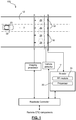
Figure 1 shows, in block diagram form, an example electronic toll collection (ETC) system; -
Figure 2 shows, in flowchart form, an example method for managing transponder battery life using a reduced-responsiveness state; -
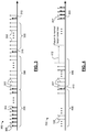
Figure 3 shows an example timing diagram illustrating the onset of a reduced-responsiveness state; -
Figure 4 shows an example timing diagram illustrating return to a normal-responsiveness state; and -
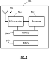
Figure 5 shows, in block diagram form, an example transponder. - Similar reference numerals are used in different figures to denote similar components.
- A method of managing battery life of a toll transponder, which method is implemented by the toll transponder, includes repeatedly detecting trigger signals and sending a response signal in reply to each trigger signal, and determining that a threshold parameter has been reached during the repeatedly detecting and, based on that determination, entering a reduced-responsiveness state during which some detected trigger signals are ignored.
- Reference is first made to
Figure 1 , which shows, in block diagram form, an example electronic toll collection (ETC) system 10. The ETC system 10 is employed in connection with aroadway 12 having one or more lanes for vehicular traffic. The arrow indicates the direction of travel in theroadway 12. For diagrammatic purposes, avehicle 22 is illustrated in theroadway 12. In some instances, theroadway 12 may be an access roadway leading towards or away from a toll highway. In other instances, theroadway 12 may be the toll highway. -
Vehicle 22 is shown inFigure 1 with atransponder 20 mounted to the windshield. In other embodiments, thetransponder 20 may be mounted in other locations. - The ETC system includes
antennas 18 connected to an automatic vehicle identification (AVI)reader 17. Thereader 17 generates signals for transmission by theantennas 18 and processes signals that are received by theantennas 18. Thereader 17 includes aprocessor 35 and one or more radio frequency (RF) modules 24 (one is shown for clarity). In many implementations, eachantenna 18 may have adedicated RF module 24; although in some embodiments anRF module 24 may be shared by more than oneantenna 18 through time multiplexing. In some implementations, theRF modules 24 may be separate from thereader 17. In some example implementations, theRF modules 24 may be integrated into theirrespective antennas 18. - The
antennas 18 are directional transmit and receive antennas which, in the illustrated embodiment, are oriented to define a series ofcapture zones 26 extending across theroadway 12 in an orthogonal direction. The arrangement ofcapture zones 26 define the communication zone within which toll transactions are conducted using an ETC communications protocol. The arrangement shown is only one example embodiment; it will be understood that other configurations and arrangements of capture zones are possible. In some embodiments, the transmit and receive functions may be implemented using separate antennas. - The ETC system 10 may operate, for example, within the industrial, scientific and medical (ISM) radio bands at 902-928 MHz. For example, the ETC system 10 may conduct communications at 915 MHz. In other embodiments, other bands/frequencies may be used, including 2.4 GHz, 5.9 GHz, etc.
- In this embodiment, the ETC system 10 operates using an active transponder. In general, an active transponder is battery powered and generates and transmits a response signal when it detects a trigger signal broadcast from one of the
antennas 18. The ETC system 10, and in particular thereader 17 andantennas 18, continuously poll thecapture zones 26 using time-division multiplexing to avoid interference in overlappingcapture zones 26. In another example, the ETC system 10 may alternatively, or also, use frequency-division multiplexing. The polling may take the form of sending a trigger or polling signal and awaiting a response signal from any transponder that happens to be within thecapture zone 26. In the application herein the term "trigger signal" is used to refer to a signal intended to cause any transponder in the capture zone to send a response signal if it detects the trigger signal. - In the ETC system 10, vehicles are first detected when they enter the
capture zones 26 and the vehicle-mountedtransponder 20 responds to a trigger signal broadcast by one of theantennas 18. The frequency of the polling is such that as thevehicle 22 traverses thecapture zones 26, thetransponder 20 receives and responds to trigger signals from the reader 17 a number of times. Each of these trigger-responses may be referred to as a "handshake" or "reader-transponder handshake" herein. - Once the
reader 17 identifies thetransponder 20 as a newly-arrivedtransponder 20 it will initiate conduct of an ETC toll transaction. This may include programming thetransponder 20 through sending a programming signal that thetransponder 20 uses to update the transponder information stored in memory on thetransponder 20. - ETC transponders are now being leveraged for additional applications. For example, in some situations roadside readers may be used to count vehicles for traffic monitoring and management purposes. In some cases, toll transponders may be used for parking or other electronic payment transactions, meaning that readers are installed at parking lot entrances, fast-food drive-through lanes, gas stations, or other locations. In some situations, these additional uses are being implemented by third parties and not the original ETC infrastructure provider. Accordingly, toll transponders may end up being polled more often that might be anticipated by the ETC infrastructure provider. This extra polling impacts the battery-life of the transponder, which is often guaranteed by the ETC infrastructure operator based upon projected use in the ETC system.
- This may be particularly troublesome if a transponder-equipped vehicle is parked or idling in close proximity to a reader (whether an ETC reader or another type of reader), in which case the transponder may be continuously and repeated bombarded with trigger signals to which it generates and transmits a response signal. This can result in far more trigger-read cycles than was originally anticipated by the ETC infrastructure provider, and will negatively impact the lifespan of the toll transponder battery.
- In accordance with one aspect of the present application, a transponder is configured to recognize when it is being subjected to trigger signals over an extended period of time and, in response, reduce its responsiveness. In a further aspect, the transponder may be configured to recognize when the repeated trigger signal situation has been resolved and then return to normal responsiveness.
- Reference is now made to
Figure 2 , which shows, in flowchart form, anexample process 200 for managing battery life in a transponder. In this example, the transponder is configured, under normal operating conditions, to respond to a detected trigger signal by sending a response signal. The transponder may be configured to wait a short period of time after detecting the trigger signal before transmitting the response signal in order to avoid interference; however, in general it is configured to respond to every trigger signal detected by sending a response signal. In some embodiments, the response signal contains transponder identification data, including the transponder serial number and other such data. - In the
example process 200, the transponder determines inoperation 202 if it detects a trigger signal. In other words, the transponder listens for trigger signals. Once a trigger signal is detected the transponder sends a response signal, as indicated byoperation 204. Inoperation 206, the transponder evaluates whether a first timer is on. If not, then it turns on the first timer inoperation 208 and returns tooperation 202 to await a further trigger signal. If the first timer has already been turned on, then the transponder evaluates whether it has been running for more than a maximum threshold length of time inoperation 210. In essence, the first timer is used to determine for how long the transponder has been subjected to repeated trigger pulses. - Note that if a trigger signal is not detected in
operation 202, the transponder monitors the time since the last trigger signal was detected and if a second timer which is restarted on receipt of each trigger signal and measures the time since receipt of a most recent trigger signal exceeds a threshold value when compared thereto, as indicated byoperation 205, then inoperation 207 the first timer is zeroed and turned off. It will then only be restarted inoperation 208 when the next trigger signal is detected. In this manner, operations 205-210 use the first timer to track whether the transponder has been consistently receiving repeated trigger signals for more than a threshold length of time. If the regular trigger signals cease for a certain period, then the first timer is reset and is restarted when the transponder next starts to receive trigger signals. - If the first timer exceeds the maximum threshold length of time, then the transponder deems itself to be in a static situation in which trigger signals will continue to be received that arc unconnected with processing of a toll transaction. Accordingly, the transponder is configured to enter a state of reduced responsiveness in this situation.
- After the first timer is found to exceed the maximum threshold length of time, then in
operation 212, the transponder starts a silence period. The first timer may be zeroed and turned off at this point. The silence period is a period during which the transponder ignores trigger signals. It may be configured to last for a predetermined length of time, or a predetermined number of trigger signals. This may be implemented using a silence timer in some embodiments. In other embodiments, the silence period is configured to last indefinitely, as long as the transponder is still receiving regular successive trigger signals. A third timer may also be used to determine whether the situation of repeated triggers signals has changed and that the transponder should transition from the reduced-responsiveness state back to the normal state. Accordingly,operation 212 may further include starting the third timer for measuring the time since the last trigger pulse was detected. - The transponder then listens for a trigger signal in
operation 214. If no trigger pulse is detected, then the transponder determines whether the third timer has expired as indicated inoperation 218. Thisoperation 218 corresponds to monitoring whether the time since the last trigger pulse was detected has exceeded some preset threshold duration that indicates that the transponder is no longer static in a capture zone of a reader and being subjected to repeated trigger pulses. If this threshold duration has elapsed, then the transponder leaves the reduced-responsiveness state and returns tooperation 202 to operate in the normal responsiveness state. - If a trigger signal is detected, then in
operation 216, the transponder resets or zeros the third timer, i.e. it restarts the timer measuring the time since the last trigger signal was detected. Inoperation 220 the transponder determines whether the silence period has elapsed. That is, it determines whether the transponder should continue ignoring trigger signals or whether it should send a response. As noted above, this may be based upon a count of trigger signals detected or may be based on an elapsed period of time, in some embodiments. If the silence period has not elapsed, then theprocess 200 returns tooperation 214 to listen for further trigger signals. However, if the silence period has elapsed, then inoperation 222 the transponder sends a response signal in reply to the detected trigger signal. It then returns tooperation 212 to restart the silence period. - It will be understood that in some examples the silence period may be set such that the transponder responds to every Nth trigger signal in the reduced-responsiveness state. In one example, the transponder may be configured to respond to every 10th trigger signal. In some cases, the level of responsiveness (e.g. the value of N) may be set by a reader or by a user. In some other examples, the silence period may be set such that other levels of responsiveness are implemented in that state. As one example, the transponder may be configured to respond to multiple trigger signals (i.e. a burst of trigger signals) before re-entering the non-responsive portion of the reduced-responsiveness state.
- In one embodiment according to the invention, the transponder is configured to enter a morereduced-responsiveness state if the transponder is deemed to have been in the reduced-responsiveness state for a certain period of time. For example, if the transponder is responding to every tenth trigger signal and remains in the reduced-responsiveness state for a certain period of time (e.g. 5, 10 or 20 minutes), then the transponder may reconfigure the silence period such that it responds to every hundredth trigger signal. Further states of reduced responsiveness may also be defined in some embodiments.
- An example is illustrated by a timing diagram 300 shown in
Figure 3 . The timing diagram 300 shows (from left to right) a train of regular trigger signals 302 detected by a transponder within the coverage area or capture zone of a reader. - In this example, the transponder begins by sending a
response signal 304 to each trigger signal 302 detected. This occurs until the first time elapses 306, indicating that the transponder has consistently detected trigger signals for more than the threshold length of time. At this point in time, the transponder enters its reduced-responsiveness state and implements asilence period 308. In this example, thesilence period 308 is a preset duration during which the transponder ignores detected trigger signals and sends no response signal in reply. - After the
silence period 308 elapses, the transponder sends aresponse signal 310, following which it implements anothersilence period 308. This continues until the transponder determines that it should return to the normal responsiveness state. -
Figure 4 shows a timing diagram 400 that illustrates an example of the return to a normal responsiveness state. In this example, the transponder is in a reduced-responsiveness state in which it ignores detected trigger signals during asilence period 408, then sends aresponse signal 410 in reply to a detectedtrigger signal 402 after eachsilence period 408, before implementing thenext silence period 408. - As indicated by
reference numeral 412, if the transponder fails to detect a trigger signal for a predetermined length of time, then it returns to normal responsiveness. This corresponds to expiry of the third timer discussed in connection withFigure 2 . It will be noted that after expiry of thethird timer 412, when the transponder next detects trigger signals 402 it sends aresponse signal 404 to each trigger signal without interspersing responses with silence periods. - The maximum threshold length of time that marks expiry of the first timer (i.e. the transition to the reduced-responsiveness state) may be set having regard to the maximum length of time normally used to determine lane assignment and process a toll transaction in an ETC system. The maximum may take into account various scenarios that may be encountered, including slow moving traffic. In some cases, the transponder may be permitted to enter the reduced-responsiveness state when positioned in an ETC toll plaza for an extended period of time, such as when caught in a traffic stoppage, provided the reduced responsiveness does not impact lane determination/assignment and/or toll transaction processing.
- In some embodiments, the transponder may be configured to temporarily or permanently disable the reduced-responsiveness state (i.e. remain in a normal responsiveness state) in response to a command from the reader. In some embodiments, the transponder may be configured to alter aspects of the foregoing processes on command from the reader. For example, the reader may instruct the transponder to delay onset of the reduced-responsiveness state by causing the transponder to increase the maximum threshold length of time against which the first timer is measured for determining whether to enter the reduced-responsiveness state. Other aspects of the processes described herein may be adjustable by way of reader command.
- Reference is now made to
Figure 5 , which shows, in block diagram form, an example embodiment of atransponder 500. Thetransponder 500 includes aprocessor 502,memory 508, anRF transceiver 504, anantenna 506, and abattery 510. It will be appreciated that this is a subset of the components that may be found in many implementations of thetransponder 500. - The
RF transceiver 504 and theantenna 506 are configured to detect and demodulate RF signals, particularly those in the range used by an associated ETC system. TheRF transceiver 504 is also configured to generate RF signals modulated with information from theprocessor 502 and/ormemory 508 for transmission using theantenna 506. Theprocessor 502 in this example operates under stored program control. Software for configuring theprocessor 502 may be stored in memory within theprocessor 502 or in thememory 508. Theprocessor 502 is thus configured to implement one or more of the example processes discussed herein for determining when to enter a reduced-responsiveness state and determining when to return to a normal-responsiveness state. It will be appreciated that the diagram ofFigure 5 is illustrative of one embodiment only. In one other example, theprocessor 502 may be implemented as a hardware state machine, requiring no software, and configured to implement one or more of the example processes described herein. - The
processor 502 or theRF transceiver 504, or both, may be implemented by way of programmable integrated circuit components, application-specific integrated circuits, analog devices, or combinations of those components. - Certain adaptations and modifications of the invention will be obvious to those skilled in the art. Therefore, the above discussed embodiments are considered to be illustrative and not restrictive, the scope of the invention being indicated by the appended claims rather than the foregoing description.
Claims (10)
- A method of managing battery life of a toll transponder, the method implemented by the toll transponder (500) comprising:repeatedly detecting (202) trigger signals (302, 402) and sending a response signal (304, 404) in reply to each trigger signal (302, 402); anddetermining (210) that a threshold parameter has been reached during the repeatedly detecting and, based on that determination, entering (212) a reduced-responsiveness state during which some detected trigger signals (302, 402) are ignored,wherein the threshold parameter comprises a maximum time since receipt of a first trigger signal (302, 304) and during which subsequent trigger signals (302, 304) are consistently received within a threshold time value of each other,
wherein entering the reduced-responsiveness state comprises:
cyclically,ignoring detected trigger signals (302, 402) and sending no response signal during a silence period (308, 408), anddetecting (214) one or more trigger signals (302, 402) after the silence period (308, 408) and sending (222) a response signal (310, 410) to each of the one or more trigger signals (302, 402), andwherein said silence period (308, 408) is reconfigured to be longer when the transponder (500) has been in the reduced-responsiveness state for a pre-defined period of time. - The method of claim 1, wherein repeatedly detecting comprises:starting (208) a first timer on detection (202) of the first trigger signal (302, 402);restarting a second timer on receipt of each trigger signal (302, 402), wherein the second timer measures the time since receipt of a most recent trigger signal (302, 402);detecting (202) and responding (204) to the subsequent trigger signals (302, 402); andwhile detecting (202) and responding (204) to subsequent trigger signals (302, 402), determining (210) that the time elapsed between successive trigger signals (302, 402) does not exceed the threshold time value by comparing the second timer to the threshold time value;further comprising zeroing (207) the first timer if the time elapsed between successive trigger signals (302, 402) exceeds the threshold time value, and restarting (208) the first timer when a next trigger signal (302, 402) is received;
wherein determining (210) that a threshold parameter has been reached comprises determining that the first timer has exceeded said maximum time. - The method of claim 1 or 2, wherein cyclically ignoring and detecting (214) comprises:starting (212) the silence period (308, 408);detecting (214) trigger signals (302, 402) during the silence period (308, 408) and sending no response signal;determining (220) that the silence period (308, 408) has expired;sending (222) the response signal (310, 410) in response to one or more subsequently detected trigger signals (302, 402); andrepeating the starting (212), detecting (214), determining (220), and sending (222) provided trigger signals (302, 402) continue to be detected within a threshold time value of each other.
- The method of claim 3, wherein determining (220) that the silence period (308, 408) has expired comprises one of:determining that a maximum number of trigger signals (302, 402) have been ignored during the silence period (308, 408); anddetermining that a silence period duration has elapsed.
- A toll transponder, comprising an antenna, an RF transceiver (504), a power source (510), a processor (502), and memory (508), and wherein the processor (502) is configured to:repeatedly detect (202) trigger signals (302, 402) and to send (204) a response signal (304, 404) in reply to each trigger signal (302, 402); anddetermine (210) that a threshold parameter has been reached during the repeatedly detecting (202) and, based on that determination, enter (212) a reduced-responsiveness state during which some detected trigger signals (302, 402) are ignored,wherein the threshold parameter comprises a maximum time since receipt of a first trigger signal (302, 402) and during which subsequent trigger signals (302, 304) are consistently received within a threshold time value of each other;wherein the processor (502) is further configured to enter the reduced-responsiveness state by:
cyclically,ignoring detected trigger signals (302, 402) and sending no response signal during a silence period (308, 408), anddetecting (214) one or more trigger signals (302, 402) after the silence period (308, 408) and sending (222) a response signal (310, 410) to each of the one or more trigger signals (302, 402), andwherein the transponder (500) is further configured to reconfigure said silence period (308, 408) to be longer when the transponder (550) has been in the reduced-responsiveness state for a pre-defined period of time. - The toll transponder of claim 5, wherein the processor (502) is configured to repeatedly detect by:starting (208) a first timer on detection of the first trigger signal (302, 402);restarting a second timer on receipt of each trigger signal (302, 402), wherein the second timer measures the time since receipt of a most recent trigger signal (302, 402);detecting (202) and responding (204) to the subsequent trigger signals (302, 402); andwhile detecting (202) and responding (204) to subsequent trigger signals (302, 402), determining (210) that the time elapsed between successive trigger signals (302, 402) does not exceed the threshold time value by comparing the second timer to the threshold time value;wherein the processor (502) is configured to determine (210) that a threshold parameter has been reached by determining that the first timer has exceeded said maximum time.
- The toll transponder of claim 6, wherein the processor (502) is further configured to zero (207) the first timer if the time elapsed between successive trigger signals (302, 402) exceeds the threshold time value, and restart (208) the first timer when a next trigger signal (302, 402) is received.
- The toll transponder of any one of claims 5 to 7, wherein cyclically ignoring and detecting comprises:starting (212) the silence period (308, 408);detecting (214) trigger signals (304, 402) during the silence period (308, 408) and sending no response signal;determining (220) that the silence period (308, 408) has expired;sending (222) the response signal (310, 410) in response to one or more subsequently detected trigger signals (302, 402); andrepeating the starting (212), detecting (214), determining (220), and sending (222) provided trigger signals (302, 402) continue to be detected within a threshold time value of each other.
- The toll transponder of claim 8, wherein determining (220) that the silence period (308, 408) has expired comprises one of:determining that a maximum number of trigger signals (302, 402) have been ignored during the silence period (308, 408); anddetermining that a silence period duration has elapsed.
- The toll transponder of claim 8, wherein the processor is further configured to, if a trigger signal (302, 402) is not detected within a threshold time value of a previous trigger signal (302, 402), cancel the cycle of ignoring and detecting (214) and return to the operation of repeatedly detecting (202) a trigger signal (302, 402) and sending a response signal (304, 404) in reply to each trigger signal (302, 402).
Applications Claiming Priority (1)
| Application Number | Priority Date | Filing Date | Title |
|---|---|---|---|
| CA2796278A CA2796278C (en) | 2012-11-15 | 2012-11-15 | Methods for prolonging battery life in toll transponders |
Publications (3)
| Publication Number | Publication Date |
|---|---|
| EP2733678A2 EP2733678A2 (en) | 2014-05-21 |
| EP2733678A3 EP2733678A3 (en) | 2016-12-07 |
| EP2733678B1 true EP2733678B1 (en) | 2021-12-01 |
Family
ID=49356190
Family Applications (1)
| Application Number | Title | Priority Date | Filing Date |
|---|---|---|---|
| EP13187247.5A Active EP2733678B1 (en) | 2012-11-15 | 2013-10-03 | Methods for prolonging battery life in toll transponders |
Country Status (6)
| Country | Link |
|---|---|
| US (1) | US9911015B2 (en) |
| EP (1) | EP2733678B1 (en) |
| BR (1) | BR102013034011B1 (en) |
| CA (1) | CA2796278C (en) |
| ES (1) | ES2902250T3 (en) |
| MX (1) | MX341607B (en) |
Families Citing this family (2)
| Publication number | Priority date | Publication date | Assignee | Title |
|---|---|---|---|---|
| ITMI20121548A1 (en) | 2012-09-18 | 2014-03-19 | Medacta Int Sa | APPARATUS FOR POSITIONING THE LOWER ARTH OF A PATIENT IN OPERATIVE OFFICE, IN PARTICULAR FOR REPLACEMENT OPERATIONS OF THE ANCHOR WITH A FRONT APPROACH, AND A SURGICAL POSITIONING SYSTEM INCLUDING THE APPLIANCE |
| CN111681427B (en) * | 2020-06-16 | 2022-04-08 | 青岛理工大学 | An accurate identification method of ETC of expressway entrance and exit based on artificial intelligence |
Family Cites Families (17)
| Publication number | Priority date | Publication date | Assignee | Title |
|---|---|---|---|---|
| US5157375A (en) * | 1987-12-28 | 1992-10-20 | Clifford Electronics, Inc. | Electronic vehicle security system |
| US5471212A (en) | 1994-04-26 | 1995-11-28 | Texas Instruments Incorporated | Multi-stage transponder wake-up, method and structure |
| US5525992A (en) * | 1994-11-14 | 1996-06-11 | Texas Instruments Deutschland Gmbh | Method and system for conserving power in a recognition system |
| JP2885112B2 (en) * | 1995-01-27 | 1999-04-19 | 株式会社デンソー | Semiconductor integrated circuit |
| JP3211674B2 (en) * | 1996-08-22 | 2001-09-25 | 株式会社デンソー | Vehicle communication device |
| JP3641572B2 (en) * | 2000-03-31 | 2005-04-20 | 三菱電機株式会社 | Onboard equipment for ETC information communication control |
| US7565307B1 (en) * | 2000-12-21 | 2009-07-21 | Tc License Ltd. | Automatic payment method using RF ID tags |
| AU2003253585A1 (en) * | 2002-03-14 | 2003-11-11 | Eices Research, Inc. | A cooperative vehicular identification system |
| US7262711B2 (en) * | 2004-10-20 | 2007-08-28 | Mark Iv Industries Corp. | External indicator for electronic toll communications |
| US7688181B2 (en) * | 2006-09-06 | 2010-03-30 | Savi Technology, Inc. | Method and apparatus for avoiding overpolling |
| JP4450246B2 (en) * | 2007-07-11 | 2010-04-14 | 株式会社デンソー | DSRC OBE, DSRC OBE, program for the same, and communication system |
| US20090115578A1 (en) * | 2007-11-06 | 2009-05-07 | Geissler Randolph K | Radio frequency animal tracking system |
| US8228205B2 (en) * | 2008-01-23 | 2012-07-24 | Mark Iv Ivhs, Inc. | Vehicle lane discrimination in an electronic toll collection system |
| CA2652731A1 (en) * | 2008-02-07 | 2009-08-07 | Mark Iv Industries Corp. | Real-time location systems and methods |
| ES2341698B1 (en) * | 2008-12-23 | 2011-05-31 | Vodafone España, S.A.U. | SYSTEM AND METHOD OF COLLECTION OR OBSERVANCE OF ROAD USE, BASED ON STANDARD CELL NETWORK MECHANISMS. |
| US8532955B2 (en) * | 2009-02-26 | 2013-09-10 | Apple Inc. | Minimization of false trigger in a mobile electronic system |
| SI2660793T1 (en) * | 2012-05-03 | 2015-01-30 | Kapsch Trafficcom Ag | Method and device for identifying a vehicle using a space |
-
2012
- 2012-11-15 CA CA2796278A patent/CA2796278C/en active Active
-
2013
- 2013-10-03 ES ES13187247T patent/ES2902250T3/en active Active
- 2013-10-03 EP EP13187247.5A patent/EP2733678B1/en active Active
- 2013-10-14 US US14/052,950 patent/US9911015B2/en active Active
- 2013-11-15 MX MX2013013364A patent/MX341607B/en active IP Right Grant
- 2013-11-18 BR BR102013034011-1A patent/BR102013034011B1/en active IP Right Grant
Also Published As
| Publication number | Publication date |
|---|---|
| CA2796278A1 (en) | 2014-05-15 |
| CA2796278C (en) | 2019-04-30 |
| MX2013013364A (en) | 2014-05-22 |
| US9911015B2 (en) | 2018-03-06 |
| ES2902250T3 (en) | 2022-03-25 |
| BR102013034011A2 (en) | 2016-03-15 |
| MX341607B (en) | 2016-08-23 |
| EP2733678A2 (en) | 2014-05-21 |
| US20140132398A1 (en) | 2014-05-15 |
| BR102013034011B1 (en) | 2021-12-28 |
| EP2733678A3 (en) | 2016-12-07 |
Similar Documents
| Publication | Publication Date | Title |
|---|---|---|
| US7015802B2 (en) | Vehicle tag reader | |
| US7417548B2 (en) | Adjusting RFID waveform shape in view of signal from an RFID tag | |
| US7262711B2 (en) | External indicator for electronic toll communications | |
| US7408466B2 (en) | Adjusting RFID waveform shape in view of detected RF energy | |
| US7522092B2 (en) | Radar apparatus and radar system for a vehicle | |
| US7436308B2 (en) | Adjusting RFID waveform shape in view of signal from another reader | |
| US7391329B2 (en) | Performance driven adjustment of RFID waveform shape | |
| US20080018489A1 (en) | Systems and methods for synchronizing a plurality of rfid interrogators in a theatre of operation | |
| EP2599068B1 (en) | An intelligent transportation systems device | |
| US20080291889A1 (en) | Wireless communication method and apparatus | |
| US20160379026A1 (en) | System for the dynamic reading of data from transponders | |
| CA2344013A1 (en) | Vehicle position determination system & method | |
| US20070075838A1 (en) | Method and apparatus for avoiding radio frequency identification (RFID) tag response collisions | |
| JP3641572B2 (en) | Onboard equipment for ETC information communication control | |
| CN112911553B (en) | Sensitivity monitoring and early warning method and device | |
| CN103587496A (en) | Wireless data communication apparatus, system and method | |
| CN112203255A (en) | Control method and system for on-board unit, storage medium, and electronic apparatus | |
| CN112203256B (en) | Control method and device of vehicle-mounted unit, storage medium and electronic device | |
| US9911015B2 (en) | Methods for prolonging battery life in toll transponders | |
| CN118433690B (en) | Data transmission method and device for ETC transaction and electronic equipment | |
| JPH08223080A (en) | Communication equipment for vehicle | |
| WO2008017889A1 (en) | Improvements relating to rfid readers | |
| CN113487751B (en) | Information interaction method and device and electronic license plate | |
| WO2001065481A1 (en) | Radio tag system and method with tag interference avoidance | |
| JP2002042191A (en) | Narrow area radiocommunication system |
Legal Events
| Date | Code | Title | Description |
|---|---|---|---|
| PUAI | Public reference made under article 153(3) epc to a published international application that has entered the european phase |
Free format text: ORIGINAL CODE: 0009012 |
|
| 17P | Request for examination filed |
Effective date: 20131003 |
|
| AK | Designated contracting states |
Kind code of ref document: A2 Designated state(s): AL AT BE BG CH CY CZ DE DK EE ES FI FR GB GR HR HU IE IS IT LI LT LU LV MC MK MT NL NO PL PT RO RS SE SI SK SM TR |
|
| AX | Request for extension of the european patent |
Extension state: BA ME |
|
| PUAL | Search report despatched |
Free format text: ORIGINAL CODE: 0009013 |
|
| AK | Designated contracting states |
Kind code of ref document: A3 Designated state(s): AL AT BE BG CH CY CZ DE DK EE ES FI FR GB GR HR HU IE IS IT LI LT LU LV MC MK MT NL NO PL PT RO RS SE SI SK SM TR |
|
| AX | Request for extension of the european patent |
Extension state: BA ME |
|
| RIC1 | Information provided on ipc code assigned before grant |
Ipc: G07B 15/06 20110101AFI20161101BHEP |
|
| STAA | Information on the status of an ep patent application or granted ep patent |
Free format text: STATUS: REQUEST FOR EXAMINATION WAS MADE |
|
| R17P | Request for examination filed (corrected) |
Effective date: 20170116 |
|
| RBV | Designated contracting states (corrected) |
Designated state(s): AL AT BE BG CH CY CZ DE DK EE ES FI FR GB GR HR HU IE IS IT LI LT LU LV MC MK MT NL NO PL PT RO RS SE SI SK SM TR |
|
| STAA | Information on the status of an ep patent application or granted ep patent |
Free format text: STATUS: EXAMINATION IS IN PROGRESS |
|
| 17Q | First examination report despatched |
Effective date: 20170411 |
|
| GRAP | Despatch of communication of intention to grant a patent |
Free format text: ORIGINAL CODE: EPIDOSNIGR1 |
|
| STAA | Information on the status of an ep patent application or granted ep patent |
Free format text: STATUS: GRANT OF PATENT IS INTENDED |
|
| GRAJ | Information related to disapproval of communication of intention to grant by the applicant or resumption of examination proceedings by the epo deleted |
Free format text: ORIGINAL CODE: EPIDOSDIGR1 |
|
| STAA | Information on the status of an ep patent application or granted ep patent |
Free format text: STATUS: EXAMINATION IS IN PROGRESS |
|
| INTG | Intention to grant announced |
Effective date: 20210324 |
|
| INTC | Intention to grant announced (deleted) | ||
| GRAP | Despatch of communication of intention to grant a patent |
Free format text: ORIGINAL CODE: EPIDOSNIGR1 |
|
| STAA | Information on the status of an ep patent application or granted ep patent |
Free format text: STATUS: GRANT OF PATENT IS INTENDED |
|
| INTG | Intention to grant announced |
Effective date: 20210614 |
|
| GRAS | Grant fee paid |
Free format text: ORIGINAL CODE: EPIDOSNIGR3 |
|
| GRAA | (expected) grant |
Free format text: ORIGINAL CODE: 0009210 |
|
| STAA | Information on the status of an ep patent application or granted ep patent |
Free format text: STATUS: THE PATENT HAS BEEN GRANTED |
|
| AK | Designated contracting states |
Kind code of ref document: B1 Designated state(s): AL AT BE BG CH CY CZ DE DK EE ES FI FR GB GR HR HU IE IS IT LI LT LU LV MC MK MT NL NO PL PT RO RS SE SI SK SM TR |
|
| REG | Reference to a national code |
Ref country code: GB Ref legal event code: FG4D |
|
| REG | Reference to a national code |
Ref country code: AT Ref legal event code: REF Ref document number: 1452524 Country of ref document: AT Kind code of ref document: T Effective date: 20211215 Ref country code: CH Ref legal event code: EP |
|
| REG | Reference to a national code |
Ref country code: IE Ref legal event code: FG4D |
|
| REG | Reference to a national code |
Ref country code: DE Ref legal event code: R096 Ref document number: 602013080245 Country of ref document: DE |
|
| REG | Reference to a national code |
Ref country code: SE Ref legal event code: TRGR |
|
| REG | Reference to a national code |
Ref country code: LT Ref legal event code: MG9D Ref country code: ES Ref legal event code: FG2A Ref document number: 2902250 Country of ref document: ES Kind code of ref document: T3 Effective date: 20220325 |
|
| REG | Reference to a national code |
Ref country code: NL Ref legal event code: MP Effective date: 20211201 |
|
| PG25 | Lapsed in a contracting state [announced via postgrant information from national office to epo] |
Ref country code: RS Free format text: LAPSE BECAUSE OF FAILURE TO SUBMIT A TRANSLATION OF THE DESCRIPTION OR TO PAY THE FEE WITHIN THE PRESCRIBED TIME-LIMIT Effective date: 20211201 Ref country code: LT Free format text: LAPSE BECAUSE OF FAILURE TO SUBMIT A TRANSLATION OF THE DESCRIPTION OR TO PAY THE FEE WITHIN THE PRESCRIBED TIME-LIMIT Effective date: 20211201 Ref country code: FI Free format text: LAPSE BECAUSE OF FAILURE TO SUBMIT A TRANSLATION OF THE DESCRIPTION OR TO PAY THE FEE WITHIN THE PRESCRIBED TIME-LIMIT Effective date: 20211201 Ref country code: BG Free format text: LAPSE BECAUSE OF FAILURE TO SUBMIT A TRANSLATION OF THE DESCRIPTION OR TO PAY THE FEE WITHIN THE PRESCRIBED TIME-LIMIT Effective date: 20220301 |
|
| PG25 | Lapsed in a contracting state [announced via postgrant information from national office to epo] |
Ref country code: PL Free format text: LAPSE BECAUSE OF FAILURE TO SUBMIT A TRANSLATION OF THE DESCRIPTION OR TO PAY THE FEE WITHIN THE PRESCRIBED TIME-LIMIT Effective date: 20211201 Ref country code: NO Free format text: LAPSE BECAUSE OF FAILURE TO SUBMIT A TRANSLATION OF THE DESCRIPTION OR TO PAY THE FEE WITHIN THE PRESCRIBED TIME-LIMIT Effective date: 20220301 Ref country code: LV Free format text: LAPSE BECAUSE OF FAILURE TO SUBMIT A TRANSLATION OF THE DESCRIPTION OR TO PAY THE FEE WITHIN THE PRESCRIBED TIME-LIMIT Effective date: 20211201 Ref country code: HR Free format text: LAPSE BECAUSE OF FAILURE TO SUBMIT A TRANSLATION OF THE DESCRIPTION OR TO PAY THE FEE WITHIN THE PRESCRIBED TIME-LIMIT Effective date: 20211201 Ref country code: GR Free format text: LAPSE BECAUSE OF FAILURE TO SUBMIT A TRANSLATION OF THE DESCRIPTION OR TO PAY THE FEE WITHIN THE PRESCRIBED TIME-LIMIT Effective date: 20220302 |
|
| PG25 | Lapsed in a contracting state [announced via postgrant information from national office to epo] |
Ref country code: NL Free format text: LAPSE BECAUSE OF FAILURE TO SUBMIT A TRANSLATION OF THE DESCRIPTION OR TO PAY THE FEE WITHIN THE PRESCRIBED TIME-LIMIT Effective date: 20211201 |
|
| PG25 | Lapsed in a contracting state [announced via postgrant information from national office to epo] |
Ref country code: SM Free format text: LAPSE BECAUSE OF FAILURE TO SUBMIT A TRANSLATION OF THE DESCRIPTION OR TO PAY THE FEE WITHIN THE PRESCRIBED TIME-LIMIT Effective date: 20211201 Ref country code: SK Free format text: LAPSE BECAUSE OF FAILURE TO SUBMIT A TRANSLATION OF THE DESCRIPTION OR TO PAY THE FEE WITHIN THE PRESCRIBED TIME-LIMIT Effective date: 20211201 Ref country code: RO Free format text: LAPSE BECAUSE OF FAILURE TO SUBMIT A TRANSLATION OF THE DESCRIPTION OR TO PAY THE FEE WITHIN THE PRESCRIBED TIME-LIMIT Effective date: 20211201 Ref country code: PT Free format text: LAPSE BECAUSE OF FAILURE TO SUBMIT A TRANSLATION OF THE DESCRIPTION OR TO PAY THE FEE WITHIN THE PRESCRIBED TIME-LIMIT Effective date: 20220401 Ref country code: EE Free format text: LAPSE BECAUSE OF FAILURE TO SUBMIT A TRANSLATION OF THE DESCRIPTION OR TO PAY THE FEE WITHIN THE PRESCRIBED TIME-LIMIT Effective date: 20211201 Ref country code: CZ Free format text: LAPSE BECAUSE OF FAILURE TO SUBMIT A TRANSLATION OF THE DESCRIPTION OR TO PAY THE FEE WITHIN THE PRESCRIBED TIME-LIMIT Effective date: 20211201 |
|
| REG | Reference to a national code |
Ref country code: DE Ref legal event code: R097 Ref document number: 602013080245 Country of ref document: DE |
|
| PG25 | Lapsed in a contracting state [announced via postgrant information from national office to epo] |
Ref country code: IS Free format text: LAPSE BECAUSE OF FAILURE TO SUBMIT A TRANSLATION OF THE DESCRIPTION OR TO PAY THE FEE WITHIN THE PRESCRIBED TIME-LIMIT Effective date: 20220401 |
|
| PLBE | No opposition filed within time limit |
Free format text: ORIGINAL CODE: 0009261 |
|
| STAA | Information on the status of an ep patent application or granted ep patent |
Free format text: STATUS: NO OPPOSITION FILED WITHIN TIME LIMIT |
|
| PG25 | Lapsed in a contracting state [announced via postgrant information from national office to epo] |
Ref country code: DK Free format text: LAPSE BECAUSE OF FAILURE TO SUBMIT A TRANSLATION OF THE DESCRIPTION OR TO PAY THE FEE WITHIN THE PRESCRIBED TIME-LIMIT Effective date: 20211201 Ref country code: AL Free format text: LAPSE BECAUSE OF FAILURE TO SUBMIT A TRANSLATION OF THE DESCRIPTION OR TO PAY THE FEE WITHIN THE PRESCRIBED TIME-LIMIT Effective date: 20211201 |
|
| 26N | No opposition filed |
Effective date: 20220902 |
|
| PG25 | Lapsed in a contracting state [announced via postgrant information from national office to epo] |
Ref country code: SI Free format text: LAPSE BECAUSE OF FAILURE TO SUBMIT A TRANSLATION OF THE DESCRIPTION OR TO PAY THE FEE WITHIN THE PRESCRIBED TIME-LIMIT Effective date: 20211201 |
|
| REG | Reference to a national code |
Ref country code: AT Ref legal event code: UEP Ref document number: 1452524 Country of ref document: AT Kind code of ref document: T Effective date: 20211201 |
|
| PG25 | Lapsed in a contracting state [announced via postgrant information from national office to epo] |
Ref country code: MC Free format text: LAPSE BECAUSE OF FAILURE TO SUBMIT A TRANSLATION OF THE DESCRIPTION OR TO PAY THE FEE WITHIN THE PRESCRIBED TIME-LIMIT Effective date: 20211201 Ref country code: IT Free format text: LAPSE BECAUSE OF FAILURE TO SUBMIT A TRANSLATION OF THE DESCRIPTION OR TO PAY THE FEE WITHIN THE PRESCRIBED TIME-LIMIT Effective date: 20211201 |
|
| REG | Reference to a national code |
Ref country code: CH Ref legal event code: PL |
|
| P01 | Opt-out of the competence of the unified patent court (upc) registered |
Effective date: 20230513 |
|
| REG | Reference to a national code |
Ref country code: BE Ref legal event code: MM Effective date: 20221031 |
|
| GBPC | Gb: european patent ceased through non-payment of renewal fee |
Effective date: 20221003 |
|
| PG25 | Lapsed in a contracting state [announced via postgrant information from national office to epo] |
Ref country code: LU Free format text: LAPSE BECAUSE OF NON-PAYMENT OF DUE FEES Effective date: 20221003 |
|
| PG25 | Lapsed in a contracting state [announced via postgrant information from national office to epo] |
Ref country code: LI Free format text: LAPSE BECAUSE OF NON-PAYMENT OF DUE FEES Effective date: 20221031 Ref country code: CH Free format text: LAPSE BECAUSE OF NON-PAYMENT OF DUE FEES Effective date: 20221031 |
|
| PG25 | Lapsed in a contracting state [announced via postgrant information from national office to epo] |
Ref country code: BE Free format text: LAPSE BECAUSE OF NON-PAYMENT OF DUE FEES Effective date: 20221031 |
|
| PG25 | Lapsed in a contracting state [announced via postgrant information from national office to epo] |
Ref country code: IE Free format text: LAPSE BECAUSE OF NON-PAYMENT OF DUE FEES Effective date: 20221003 Ref country code: GB Free format text: LAPSE BECAUSE OF NON-PAYMENT OF DUE FEES Effective date: 20221003 |
|
| PG25 | Lapsed in a contracting state [announced via postgrant information from national office to epo] |
Ref country code: HU Free format text: LAPSE BECAUSE OF FAILURE TO SUBMIT A TRANSLATION OF THE DESCRIPTION OR TO PAY THE FEE WITHIN THE PRESCRIBED TIME-LIMIT; INVALID AB INITIO Effective date: 20131003 |
|
| PG25 | Lapsed in a contracting state [announced via postgrant information from national office to epo] |
Ref country code: CY Free format text: LAPSE BECAUSE OF FAILURE TO SUBMIT A TRANSLATION OF THE DESCRIPTION OR TO PAY THE FEE WITHIN THE PRESCRIBED TIME-LIMIT Effective date: 20211201 |
|
| PG25 | Lapsed in a contracting state [announced via postgrant information from national office to epo] |
Ref country code: MK Free format text: LAPSE BECAUSE OF FAILURE TO SUBMIT A TRANSLATION OF THE DESCRIPTION OR TO PAY THE FEE WITHIN THE PRESCRIBED TIME-LIMIT Effective date: 20211201 |
|
| PG25 | Lapsed in a contracting state [announced via postgrant information from national office to epo] |
Ref country code: MT Free format text: LAPSE BECAUSE OF FAILURE TO SUBMIT A TRANSLATION OF THE DESCRIPTION OR TO PAY THE FEE WITHIN THE PRESCRIBED TIME-LIMIT Effective date: 20211201 |
|
| PG25 | Lapsed in a contracting state [announced via postgrant information from national office to epo] |
Ref country code: TR Free format text: LAPSE BECAUSE OF FAILURE TO SUBMIT A TRANSLATION OF THE DESCRIPTION OR TO PAY THE FEE WITHIN THE PRESCRIBED TIME-LIMIT Effective date: 20211201 |
|
| PGFP | Annual fee paid to national office [announced via postgrant information from national office to epo] |
Ref country code: DE Payment date: 20251021 Year of fee payment: 13 |
|
| PGFP | Annual fee paid to national office [announced via postgrant information from national office to epo] |
Ref country code: AT Payment date: 20251022 Year of fee payment: 13 |
|
| PGFP | Annual fee paid to national office [announced via postgrant information from national office to epo] |
Ref country code: FR Payment date: 20251030 Year of fee payment: 13 |
|
| PGFP | Annual fee paid to national office [announced via postgrant information from national office to epo] |
Ref country code: SE Payment date: 20251021 Year of fee payment: 13 |
|
| PGFP | Annual fee paid to national office [announced via postgrant information from national office to epo] |
Ref country code: ES Payment date: 20251210 Year of fee payment: 13 |