EP2733397A1 - Seal structure using metal gasket - Google Patents
Seal structure using metal gasket Download PDFInfo
- Publication number
- EP2733397A1 EP2733397A1 EP12811926.0A EP12811926A EP2733397A1 EP 2733397 A1 EP2733397 A1 EP 2733397A1 EP 12811926 A EP12811926 A EP 12811926A EP 2733397 A1 EP2733397 A1 EP 2733397A1
- Authority
- EP
- European Patent Office
- Prior art keywords
- casing
- outer peripheral
- contact
- metal gasket
- metal
- Prior art date
- Legal status (The legal status is an assumption and is not a legal conclusion. Google has not performed a legal analysis and makes no representation as to the accuracy of the status listed.)
- Granted
Links
Images


Classifications
-
- F—MECHANICAL ENGINEERING; LIGHTING; HEATING; WEAPONS; BLASTING
- F16—ENGINEERING ELEMENTS AND UNITS; GENERAL MEASURES FOR PRODUCING AND MAINTAINING EFFECTIVE FUNCTIONING OF MACHINES OR INSTALLATIONS; THERMAL INSULATION IN GENERAL
- F16J—PISTONS; CYLINDERS; SEALINGS
- F16J15/00—Sealings
- F16J15/02—Sealings between relatively-stationary surfaces
- F16J15/06—Sealings between relatively-stationary surfaces with solid packing compressed between sealing surfaces
- F16J15/08—Sealings between relatively-stationary surfaces with solid packing compressed between sealing surfaces with exclusively metal packing
- F16J15/0887—Sealings between relatively-stationary surfaces with solid packing compressed between sealing surfaces with exclusively metal packing the sealing effect being obtained by elastic deformation of the packing
-
- F—MECHANICAL ENGINEERING; LIGHTING; HEATING; WEAPONS; BLASTING
- F16—ENGINEERING ELEMENTS AND UNITS; GENERAL MEASURES FOR PRODUCING AND MAINTAINING EFFECTIVE FUNCTIONING OF MACHINES OR INSTALLATIONS; THERMAL INSULATION IN GENERAL
- F16J—PISTONS; CYLINDERS; SEALINGS
- F16J15/00—Sealings
- F16J15/02—Sealings between relatively-stationary surfaces
- F16J15/06—Sealings between relatively-stationary surfaces with solid packing compressed between sealing surfaces
- F16J15/08—Sealings between relatively-stationary surfaces with solid packing compressed between sealing surfaces with exclusively metal packing
- F16J15/0806—Sealings between relatively-stationary surfaces with solid packing compressed between sealing surfaces with exclusively metal packing characterised by material or surface treatment
-
- F—MECHANICAL ENGINEERING; LIGHTING; HEATING; WEAPONS; BLASTING
- F16—ENGINEERING ELEMENTS AND UNITS; GENERAL MEASURES FOR PRODUCING AND MAINTAINING EFFECTIVE FUNCTIONING OF MACHINES OR INSTALLATIONS; THERMAL INSULATION IN GENERAL
- F16J—PISTONS; CYLINDERS; SEALINGS
- F16J15/00—Sealings
- F16J15/02—Sealings between relatively-stationary surfaces
- F16J15/06—Sealings between relatively-stationary surfaces with solid packing compressed between sealing surfaces
- F16J15/08—Sealings between relatively-stationary surfaces with solid packing compressed between sealing surfaces with exclusively metal packing
- F16J15/0818—Flat gaskets
-
- F—MECHANICAL ENGINEERING; LIGHTING; HEATING; WEAPONS; BLASTING
- F16—ENGINEERING ELEMENTS AND UNITS; GENERAL MEASURES FOR PRODUCING AND MAINTAINING EFFECTIVE FUNCTIONING OF MACHINES OR INSTALLATIONS; THERMAL INSULATION IN GENERAL
- F16J—PISTONS; CYLINDERS; SEALINGS
- F16J15/00—Sealings
- F16J15/02—Sealings between relatively-stationary surfaces
- F16J15/06—Sealings between relatively-stationary surfaces with solid packing compressed between sealing surfaces
- F16J15/08—Sealings between relatively-stationary surfaces with solid packing compressed between sealing surfaces with exclusively metal packing
- F16J15/0818—Flat gaskets
- F16J15/0825—Flat gaskets laminated
-
- F—MECHANICAL ENGINEERING; LIGHTING; HEATING; WEAPONS; BLASTING
- F16—ENGINEERING ELEMENTS AND UNITS; GENERAL MEASURES FOR PRODUCING AND MAINTAINING EFFECTIVE FUNCTIONING OF MACHINES OR INSTALLATIONS; THERMAL INSULATION IN GENERAL
- F16J—PISTONS; CYLINDERS; SEALINGS
- F16J15/00—Sealings
- F16J15/02—Sealings between relatively-stationary surfaces
- F16J15/06—Sealings between relatively-stationary surfaces with solid packing compressed between sealing surfaces
- F16J15/10—Sealings between relatively-stationary surfaces with solid packing compressed between sealing surfaces with non-metallic packing
- F16J15/12—Sealings between relatively-stationary surfaces with solid packing compressed between sealing surfaces with non-metallic packing with metal reinforcement or covering
- F16J15/121—Sealings between relatively-stationary surfaces with solid packing compressed between sealing surfaces with non-metallic packing with metal reinforcement or covering with metal reinforcement
- F16J15/122—Sealings between relatively-stationary surfaces with solid packing compressed between sealing surfaces with non-metallic packing with metal reinforcement or covering with metal reinforcement generally parallel to the surfaces
-
- F—MECHANICAL ENGINEERING; LIGHTING; HEATING; WEAPONS; BLASTING
- F16—ENGINEERING ELEMENTS AND UNITS; GENERAL MEASURES FOR PRODUCING AND MAINTAINING EFFECTIVE FUNCTIONING OF MACHINES OR INSTALLATIONS; THERMAL INSULATION IN GENERAL
- F16J—PISTONS; CYLINDERS; SEALINGS
- F16J15/00—Sealings
- F16J15/02—Sealings between relatively-stationary surfaces
- F16J15/06—Sealings between relatively-stationary surfaces with solid packing compressed between sealing surfaces
- F16J15/08—Sealings between relatively-stationary surfaces with solid packing compressed between sealing surfaces with exclusively metal packing
- F16J15/0818—Flat gaskets
- F16J2015/085—Flat gaskets without fold over
-
- F—MECHANICAL ENGINEERING; LIGHTING; HEATING; WEAPONS; BLASTING
- F16—ENGINEERING ELEMENTS AND UNITS; GENERAL MEASURES FOR PRODUCING AND MAINTAINING EFFECTIVE FUNCTIONING OF MACHINES OR INSTALLATIONS; THERMAL INSULATION IN GENERAL
- F16J—PISTONS; CYLINDERS; SEALINGS
- F16J15/00—Sealings
- F16J15/02—Sealings between relatively-stationary surfaces
- F16J15/06—Sealings between relatively-stationary surfaces with solid packing compressed between sealing surfaces
- F16J15/08—Sealings between relatively-stationary surfaces with solid packing compressed between sealing surfaces with exclusively metal packing
- F16J15/0818—Flat gaskets
- F16J2015/0856—Flat gaskets with a non-metallic coating or strip
Definitions
- the present invention relates to a seal structure using a metal gasket.
- the seal structure according to the present invention is used, for example, an automobile-related field, or is used in the other fields.
- a neutral salt spray test is executed as a spec evaluation item.
- a casing in the other end to which the metal gasket is installed is made of an aluminum material (including an aluminum alloy, same as above)
- salt water is piled up in (attached to) a gap between the metal gasket and the casing, and corrosion (gap corrosion) of the aluminum material due to the salt water (difference in an ion concentration) is generated by repeating a dry condition and a wet condition.
- the metal gasket achieves a seal function on the basis of a reaction of a portion coming into contact with the casing, however, the seal function is deteriorated in the case that the corrosion portion of the casing passes through a seal line.
- the present invention is made by taking the above points into consideration, and an object of the present invention is to provide a seal structure using a metal gasket, which is structured such that a gap in which the salt water stays is not formed between the metal gasket and a casing, whereby the corrosion of the casing is hard to be generated by the staying of the salt water and the seal function is maintained over a long term.
- a seal structure including one metal gasket which is arranged between a pair of casings, wherein the metal gasket is provided with a planate outer peripheral portion and a bead portion which is formed by rising up from an inner peripheral end portion of the outer peripheral portion, and is arranged so that the bead portion comes into contact with the one casing, and the outer peripheral portion comes into contact with the other casing, the bead portion elastically deforms so as to reduce its height and the outer peripheral portion elastically deforms on the basis of the elastic deformation of the bead portion, when the metal gasket is pinched by the pair of casings, and a leading end of the outer peripheral portion comes into contact with the one casing at this time, whereby any gap in which salt water stays is not formed between the one casing and the metal gasket.
- a seal structure including two metal gaskets which are arranged in a state in which the metal gaskets are overlapped between a pair of casings, wherein the metal gaskets are provided with planate outer peripheral portions and bead portions which are formed by rising up from inner peripheral end portions of the outer peripheral portions, and are arranged so that the outer peripheral portions come into contact with each other, the bead portion of the one metal gasket comes into contact with the one casing, and the bead portion of the other metal gasket comes into contact with the other casing, each of the bead portions elastically deforms so as to reduce its height and each of the outer peripheral portions elastically deforms on the basis of the elastic deformation of the bead portion, when these two metal gaskets are pinched by the pair of casings, and a leading end of the outer peripheral portion of the one metal gasket comes into contact with the one casing and the leading end of the outer peripheral portion of the other metal gasket comes into contact with the
- the seal structure described in the claim 1 or the claim 2 mentioned above wherein the metal gasket is structured such that in the case that a rubber layer is attached to a surface of a metal base plate, whereby a leading end of the outer peripheral portion comes into contact with the casing, the metal base plate does not come into contact with the casing, but the rubber layer comes into contact with the casing.
- the seal structure described in the claim 3 mentioned above wherein the rubber layer is structured such that in the case a leading end of the rubber layer protrudes out of the leading end of the metal base plate so as to protrude like an eaves shape, whereby the leading end of the outer peripheral portion comes into contact with the casing, the metal base plate is hard to come into contact with the casing.
- the seal structure according to the claim 1 of the present invention having the structure mentioned above is the structure in which one metal gasket is installed between a pair of casings, and the metal gasket is provided with the planate outer peripheral portion and the bead portion which is formed by rising up from the inner peripheral end portion of the outer peripheral portion, and is arranged so that the bead portion comes into contact with the one casing, and the outer peripheral portion comes into contact with the other casing, in the initial arrangement before being pinched.
- the bead portion elastically deforms so as to reduce its height and the outer peripheral portion elastically deforms on the basis of the elastic deformation of the bead portion, whereby the leading end of the outer peripheral portion comes into contact with the one casing at this time. Therefore, the one casing and the metal gasket are occluded therebetween by the contact, so that since the gap in which the salt water stays is not formed, it is possible to inhibit the corrosion of the casing from being generated by the staying of the salt water even in the case that the one casing is made of the aluminum material.
- the seal structure according to the claim 2 of the present invention having the structure mentioned above is the structure in which two metal gaskets are installed in a state in which the metal gaskets are overlapped between a pair of casings, the metal gaskets are respectively provided with the planate outer peripheral portions and the bead portions which are formed by rising up from the inner peripheral end portions of the outer peripheral portions, and are arranged so that the outer peripheral portions come into contact with each other, the bead portion of the one metal gasket comes into contact with the one casing at the initial state before being pinched, and the bead portion of the other metal gasket comes into contact with the other casing.
- each of the bead portions elastically deforms so as to reduce its height and each of the outer peripheral portions elastically deforms on the basis of the elastic deformation of the bead portion, when two metal gaskets are pinched by the pair of casings, and the leading end of the outer peripheral portion of the one metal gasket comes into contact with the one casing and the leading end of the outer peripheral portion of the other metal gasket comes into contact with the other casing at this time.
- the one casing and the one metal gasket are occluded therebetween, and the other casing and the other metal gasket are occluded respectively by the contact, so that since the gap in which the salt water stays is not formed, it is possible to inhibit the corrosion of the casing from being generated by the staying of the salt water even in the case that the one casing and the other casing are made of the aluminum material, respectively.
- the metal gasket is structured such that the rubber layer is attached to the surface of the metal base plate
- an electric corrosion of the casing which may be generated in the case that the casing is made of the aluminum material.
- a circuit (a battery) is formed between the casing and a bolt, and the gasket by the attachment of the salt water to the casing and a potential difference is generated, whereby the casing runs into the corrosion. Accordingly, if the metal base plate does not come into contact with the casing, the circuit is not formed.
- the leading end of the outer peripheral portion of the gasket comes into contact with the casing diagonally with any angle, and the rubber layer tends to collapse due to the reaction force, there is a risk that the metal base plate comes into contact with the casing even in the case that the rubber layer is attached to the surface of the metal base plate.
- the leading end of the rubber layer is protruded out of the leading end of the metal base plate so as to be protruded like the eaves shape.
- the rubber eaves portion is always interposed between the metal base plate and the casing, it is possible to effectively inhibit the metal base plate from coming into contact with the casing.
- the present invention achieves the following effects.
- the present invention provided with the structure mentioned above, since the gap in which the salt water stays is not formed between the one casing and the metal gasket, or between the one casing and the one metal gasket and between the other casing and the other metal gasket, respectively, it is possible to inhibit the corrosion of the casing from being generated due to the staying of the salt water. Therefore, it is possible to maintain the seal function by the metal gasket over a long term.
- the casing is made of the aluminum material, by structuring such that the metal base plate does not come into contact with the casing but the rubber layer comes into contact with the casing, and it is possible to inhibit the metal base plate from coming into contact with the casing, by setting the leading end of the rubber layer as the eaves shape.
- Fig. 1 shows a cross section of a substantial part of a metal gasket 11 which is used in a seal structure according to a first embodiment of the present invention.
- the metal gasket 11 is arranged between a pair of casings (housings or flanges) 31 and 41 and is pinched (fastened by bolts) in a gasket thickness direction (a vertical direction in the drawing), the metal gasket 11 comes to a fastened state shown in Fig. 2 .
- a left side of each of the drawings is an outer side (an outer peripheral side) of the gasket 11, that is, a sealed fluid side such as salt water, and a right side is an inner side (an inner peripheral side) of the gasket 11. Further, as shown in Fig.
- a pair of casings 31 and 41 are constructed by a combination of one casing 31 in an upper side of the drawing and the other casing 41 in a lower side of the drawing.
- one casing 31 in the upper side of the drawing is made of an aluminum material, and is a subject to be suppressed corrosion according to the present embodiment.
- the other casing 41 in the lower side of the drawing is made of an iron-based material, and is not a subject to be suppressed corrosion according to the present embodiment.
- one metal gasket 11 is installed between a pair of casings 31 and 41.
- the metal gasket 11 is integrally provided with a planate outer peripheral portion 11a, and a bead portion 11 d which is formed so as to rise up from an inner peripheral end portion of the outer peripheral portion 11a toward one side (an upward direction in the drawing) in a gasket thickness direction.
- the metal gasket 11 is provided with the planate outer peripheral portion 11 a, an inclined surface portion 11 b is integrally formed from the inner peripheral end portion of the outer peripheral portion 11a toward a diagonally upper side, and a planate inner peripheral portion 11c is integrally formed in an inner peripheral end portion of the inclined surface portion 11 b.
- the bead portion 11 d having a half bead shape and constructed by the inclined surface portion 11 b and the inner peripheral portion 11 c is set while having the planate outer peripheral portion 11a as a gasket base plate portion.
- the metal gasket 11 is provided with a metal base plate (a steel sheet layer) 12, and rubber layers (surface rubber layers) 13 and 14 are attached over a whole surface to both surfaces in a thickness direction of the metal base plate 12. Therefore, the metal gasket 11 is formed as a laminated type metal gasket (a rubber coating metal gasket) which is constructed by a combination of the metal base plate 12 and the rubber layers 13 and 14.
- an upper surface of the planate inner peripheral portion 11c constructing a part of the bead portion 11 d comes into contact (surface contact) with a lower surface of the one casing 31 in the upper side and a lower surface of the planate outer peripheral portion 11a comes into contact (surface contact) with an upper surface of the other casing 41 in the lower side.
- an initial gap is formed between the upper surfaces of the outer peripheral portion 11a and the inclined surface portion 11 b and the lower surface of the one casing 31 in the upper side.
- the gasket comes to a fastened state shown in Fig. 2 .
- the bead portion 11 d formed as the half bead shape is elastically deformed so as to reduce its height
- the planate outer peripheral portion 11a is elastically deformed diagonally on the basis of the elastic deformation of the bead portion.
- the outer peripheral portion 11a jumps up its leading end 11f upward while using a lower surface of a corner portion 11e between the outer peripheral portion 11a and the bead portion 11 d as a supporting point of a lever action, and the leading end 11f comes into contact with the lower surface of the one casing 31 in the upper side in its upper end (the upper face rubber layer 13).
- the initial gap is occluded by the contact of the leading end 11f of the outer peripheral portion 11a with the lower surface of the one casing 31 in the upper side.
- the gap in which the sealed fluid such as the salt water stays is not formed between the one casing 31 and the metal gasket 11, it is possible to inhibit the corrosion from being generated in the one casing 31 made of the aluminum material due to the staying of the salt water.
- a wedge-like gap 25 which is open like a V-shaped form in a cross section is formed between the other casing 41 in the lower side and the outer peripheral portion 11a of the metal gasket 11, however, even if the salt water stays here, the other casing 41 is made of the iron-based material and is hard to be corroded.
- the metal base plate 12 does not come into contact with the casing 31, but only the upper surface rubber layer 13 comes into contact with the casing 31. Accordingly, in this regard, it is possible to inhibit the electric corrosion from being generated even in the case that the one casing 31 is made of the aluminum material.
- the metal gasket 11 is structured by integrally forming the bead portion 11 d which is constructed by the inclined surface portion 11 b and the inner peripheral portion 11c and is formed as the half bead shape, in the inner side of the planate outer peripheral portion 11a as mentioned above, the upper surface of the corner portion 11 g of the bead portion 11 d and the leading end 11f of the outer peripheral portion 11a respectively come into close contact with the lower surface of the one casing 31 in the upper side by the rubber layer 13, and the lower surface of the corner portion 11e between the outer peripheral portion 11a and the bead portion 11 d and the leading end 11h of the inner peripheral portion 11c respectively come into contact with the upper surface of the other casing 41 in the lower side by the rubber layer 14, as shown in Fig. 2 by fastening. Therefore, two seal lines are set respectively in the upper and lower surfaces of the metal gasket 11.
- the bead portion 11 d provided in the metal gasket 11 is formed as the half bead shape which is constructed by the inclined surface portion 11 b and the inner peripheral portion 11c, however, the shape of the bead portion 11 d is not particularly limited as long as the contact of the leading end 11f of the outer peripheral portion 11a with the one casing 31 is secured by the deformation at the fastening time, and the shape may be, for example, a circular arc shape in a cross section or a trapezoidal full bead shape in a cross section.
- the gasket raw material 1 is punched so that the metal gasket 11 has a predetermined plane shape, however, in the case that a length L2 of the rubber layer 13 in one side coming into contact with the casing 31 is set to be longer than a length L1 of the metal base plate 12 (the plane shape of the rubber layer 13 in the one side coming into contact with the casing 31 is set to be size larger than the plane shape of the metal base plate 12) as shown from Fig. 3A to Fig. 3B at the punching time, the leading end of the rubber layer 13 protrudes more than the leading end of the metal base plate 12, and the leading end of the rubber layer 13 covers like the eaves the leading end of the metal base plate 12, as show in Fig.
- a direction for punching the raw material 1 is shown by an arrow P.
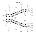
- Fig. 4 shows a cross section of a substantial part of metal gaskets 11 and 21 which are used in a seal structure according to a second embodiment of the present invention.
- the metal gaskets 11 and 21 are arranged between a pair of casings (housings or flanges) 31 and 41 in an overlapping state and are pinched (fastened by bolts) in a gasket thickness direction (a vertical direction in the drawing), the metal gaskets 11 and 21 come to a fastened state shown in Fig. 5 .
- a left side of each of the drawings is an outer side (an outer peripheral side) of the gaskets 11 and 21, that is, a sealed fluid side such as salt water, and a right side is an inner side (an inner peripheral side) of the gaskets 11 and 21.
- a pair of casings 31 and 41 are constructed by a combination of one casing 31 in an upper side of the drawing and the other casing 41 in a lower side of the drawing, and both the casings 31 and 41 are made of an aluminum material. Therefore, in the present embodiment, both the casings 31 and 41 are targeted at the suppression of corrosion.
- two metal gaskets 11 and 21 are installed between a pair of casings 31 and 41.
- the metal gaskets 11 and 21 are constructed by a combination of the one metal gasket 11 in the upper side of the drawing, and the other metal gasket 21 in the lower side of the drawing, and the respective metal gaskets 11 and 21 are integrally provided with planate outer peripheral portions 11a and 21 a which are lapped over each other at the installing time, and bead portions 11 d and 21 d which are formed so as to rise up from inner peripheral end portions of the outer peripheral portions 11 a and 21 a in a direction of being away from each other.
- the one metal gasket 11 in the upper side of the drawing is provided with the planate outer peripheral portion 11 a, an inclined surface portion 11 b is integrally formed from the inner peripheral end portion of the outer peripheral portion 11a toward a diagonally upper side, and a planate inner peripheral portion 11c is integrally formed in an inner peripheral end portion of the inclined surface portion 11 b. Therefore, the bead portion 11d having a half bead shape and constructed by the inclined surface portion 11 b and the inner peripheral portion 11c is set while having the planate outer peripheral portion 11a as a gasket base plate portion.
- the other metal gasket 21 in the lower side of the drawing is provided with the planate outer peripheral portion 21 a in the same manner, an inclined surface portion 21 b is integrally formed from the inner peripheral end portion of the outer peripheral portion 21 toward a diagonally lower side, and a planate inner peripheral portion 21 c is integrally formed in an inner peripheral end portion of the inclined surface portion 21 b. Therefore, the bead portion 21 d having a half bead shape and constructed by the inclined surface portion 21 b and the inner peripheral portion 21 c is set while having the planate outer peripheral portion 21 a as a gasket base plate portion.
- Both the metal gaskets 11 and 21 are formed as vertically symmetrical shapes with each other, formed as vertically symmetrical shapes in at least an illustrated portion, or are arranged in a vertically symmetrical manner.
- both the metal gaskets 11 and 21 are provided with metal base plates (steel sheet layers) 12 and 22, and are structured such that rubber layers (surface rubber layers) 13, 14 23 and 24 are attached over a whole surface to both surfaces in a thickness direction of the metal base plates 12 and 22. Therefore, both the metal gaskets 11and 21 are formed as laminated type metal gaskets (rubber coating metal gaskets) which are constructed by the metal base plates 12 and 22 and the rubber layers 13, 14, 23 and 24.
- an initial gap is formed between the upper surfaces of the outer peripheral portion 11a and the inclined surface portion 11b in the one metal gasket 11 in the upper side, and the lower surface of the one casing 31 in the upper side, and between the lower surfaces of the outer peripheral portion 21 a and the inclined surface portion 21 b in the other metal gasket 21 in the lower side and the upper surface of the other casing 41 in the lower side, respectively.
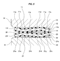
- the gaskets are thereafter pinched in the gasket thickness direction by a pair of casings 31 and 41, the gaskets comes to their fastened states shown in Fig. 5 .
- the bead portions 11 d, 21 d formed as the half bead shape are elastically deformed so as to reduce their heights, and the planate outer peripheral portions 11 a and 21 a are elastically deformed diagonally on the basis of the elastic deformation of the bead portions.
- the outer peripheral portion 11 a in the one metal gasket 11 in the upper side jumps up its leading end 11f upward while using a lower surface of a corner portion 11e between the outer peripheral portion 11a and the bead portion 11 d as a supporting point of a lever action, and the leading end 11f comes into contact with the lower surface of the one casing 31 in the upper side in its upper end (the upper face rubber layer 13).
- the initial gap is occluded by the contact of the leading end 11f of the outer peripheral portion 11a with the lower surface of the one casing 31 in the upper side.
- the gap in which the sealed fluid such as the salt water stays is not formed between the one casing 31 and the one metal gasket 11, it is possible to inhibit the corrosion from being generated in the one casing 31 made of the aluminum material due to the staying of the salt water.
- the outer peripheral portion 21 a in the other metal gasket 21 in the lower side jumps up its leading end 21f downward while using an upper surface of a corner portion 21e between the outer peripheral portion 21 a and the bead portion 21 d as a supporting point of a lever action, and the leading end 21 f comes into contact with the upper surface of the other casing 41 in the lower side in its lower end (the lower face rubber layer 24).
- the initial gap is occluded by the contact of the leading end 21 f of the outer peripheral portion 21 a with the upper surface of the other casing 41 in the lower side.
- the gap in which the sealed fluid such as the salt water stays is not formed between the other casing 41 and the other metal gasket 21, it is possible to inhibit the corrosion from being generated in the other casing 41 made of the aluminum material due to the staying of the salt water.
- a wedge-like gap 26 which is open like a V-shaped form in a cross section is formed between the outer peripheral portions 11 a and 21 a of both the metal gaskets 11 and 21, however, since the salt water does not come into contact with the casings 31 and 41 even if the salt water stays here, any corrosion is not generated in the casings 31 and 41.
- the metal base plate 12 does not come into contact with the casing 31, but only the upper surface rubber layer 13 comes into contact with the casing 31, and even in the case that the leading end 21 f of the outer peripheral portion 21 a in the other metal gasket 21 in the lower side comes into contact with the upper surface of the other casing 41 in the lower side, the metal base plate 22 does not come into contact with the casing 41, but only the lower surface rubber layer 24 comes into contact with the casing 41. Accordingly, in this regard, it is possible to inhibit the electric corrosion from being generated even in the case that each of the casings 31 and 41 is made of the aluminum material.
- the one metal gasket 11 in the upper side is structured by integrally forming the bead portion 11 d which is constructed by the inclined surface portion 11 b and the inner peripheral portion 11c and is formed as the half bead shape, in the inner side of the planate outer peripheral portion 11a as mentioned above, the upper surface of the corner portion 11 g of the bead portion 11 d and the leading end 11f of the outer peripheral portion 11a respectively come into close contact with the lower surface of the one casing 31 in the upper side, by the rubber layer 13, as shown in Fig. 5 by fastening. Therefore, two seal lines are set here.
- the other metal gasket 21 in the lower side is structured by integrally forming the bead portion 21 d which is constructed by the inclined surface portion 21 b and the inner peripheral portion 21 c and is formed as the half bead shape
- the lower surface of the corner portion 21 g of the bead portion 21 d and the leading end 21f of the outer peripheral portion 21 a respectively come into close contact with the upper surface of the other casing 41 in the lower side, by the rubber layer 24, as shown in Fig. 5 by fastening. Therefore, two seal lines are set here.
- the bead portions 11 d and 21 d provided in both the metal gaskets 11 and 21 are respectively formed as the half bead shapes which are constructed by the inclined surface portions 11 b and 21 b and the inner peripheral portions 11c and 21 c, however, the shape of the bead portions 11 d and 21 d are not particularly limited as long as the contact of the leading ends 11f and 21 f of the outer peripheral portions 11a and 21 a with the one casing 31 or the other casing 41 is secured by the deformation at the fastening time, and the shape may be, for example, a circular arc shape in a cross section or a trapezoidal full bead shape in a cross section.
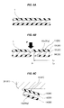
- the gasket raw material 1 is punched so that the metal gaskets 11 and 21 have a predetermined plane shape, however, in the case that a length L2 of the rubber layers 13 and 24 in one side coming into contact with the casings 31 and 41 is set to be longer than a length L1 of the metal base plates 12 and 22 (the plane shape of the rubber layers 13 and 24 in the one side coming into contact with the casings 31 and 41 is set to be size larger than the plane shape of the metal base plates 12 and 22) as shown from Fig. 6A to Fig.
- the leading ends of the rubber layers 13 and 24 protrude more than the leading ends of the metal base plates 12 and 22, and the leading ends of the rubber layers 13 and 24 cover like the eaves the leading ends of the metal base plates 12 and 22, as shown in Fig. 6C . Therefore, the metal base plates 12 and 22 are hard to come into contact with the casings 31 and 41. Accordingly, it is possible to further effectively inhibit the electric corrosion from being generated.
- a direction for punching the raw material 1 is shown by an arrow P.
Landscapes
- Engineering & Computer Science (AREA)
- General Engineering & Computer Science (AREA)
- Mechanical Engineering (AREA)
- Gasket Seals (AREA)
Abstract
Description
- The present invention relates to a seal structure using a metal gasket. The seal structure according to the present invention is used, for example, an automobile-related field, or is used in the other fields.
- For example, in the metal gasket for the automobile, in preparation for such a condition that the automobile travels in a seaside area, there is a case that a neutral salt spray test is executed as a spec evaluation item. In this case, in the case that a casing in the other end to which the metal gasket is installed is made of an aluminum material (including an aluminum alloy, same as above), salt water is piled up in (attached to) a gap between the metal gasket and the casing, and corrosion (gap corrosion) of the aluminum material due to the salt water (difference in an ion concentration) is generated by repeating a dry condition and a wet condition. The metal gasket achieves a seal function on the basis of a reaction of a portion coming into contact with the casing, however, the seal function is deteriorated in the case that the corrosion portion of the casing passes through a seal line.
- The corrosion is generated even in the case that the casing is made of an iron-based material, however, since the aluminum (Al) has a greater ionization tendency than the iron-based material (Fe), the aluminum tends to be corroded.
Al3+ + 3H2O → Al(OH)3 + 3H+
-
- Patent Document 1: Japanese Unexamined Patent Publication No.
7-224938 - Patent Document 2: Japanese Unexamined Patent Publication No.
11-241769 - Patent Document 3: Japanese Unexamined Patent Publication No.
2008-164156 - Patent Document 4: Japanese Unexamined Patent Publication No.
2009-156382 - The present invention is made by taking the above points into consideration, and an object of the present invention is to provide a seal structure using a metal gasket, which is structured such that a gap in which the salt water stays is not formed between the metal gasket and a casing, whereby the corrosion of the casing is hard to be generated by the staying of the salt water and the seal function is maintained over a long term.
- In order to achieve the object mentioned above, according to a
claim 1 of the present invention, there is provided a seal structure including one metal gasket which is arranged between a pair of casings, wherein the metal gasket is provided with a planate outer peripheral portion and a bead portion which is formed by rising up from an inner peripheral end portion of the outer peripheral portion, and is arranged so that the bead portion comes into contact with the one casing, and the outer peripheral portion comes into contact with the other casing, the bead portion elastically deforms so as to reduce its height and the outer peripheral portion elastically deforms on the basis of the elastic deformation of the bead portion, when the metal gasket is pinched by the pair of casings, and a leading end of the outer peripheral portion comes into contact with the one casing at this time, whereby any gap in which salt water stays is not formed between the one casing and the metal gasket. - Further, according to a claim 2 of the present invention, there is provided a seal structure including two metal gaskets which are arranged in a state in which the metal gaskets are overlapped between a pair of casings, wherein the metal gaskets are provided with planate outer peripheral portions and bead portions which are formed by rising up from inner peripheral end portions of the outer peripheral portions, and are arranged so that the outer peripheral portions come into contact with each other, the bead portion of the one metal gasket comes into contact with the one casing, and the bead portion of the other metal gasket comes into contact with the other casing, each of the bead portions elastically deforms so as to reduce its height and each of the outer peripheral portions elastically deforms on the basis of the elastic deformation of the bead portion, when these two metal gaskets are pinched by the pair of casings, and a leading end of the outer peripheral portion of the one metal gasket comes into contact with the one casing and the leading end of the outer peripheral portion of the other metal gasket comes into contact with the other casing at this time, whereby any gap in which salt water stays is not formed between the one casing and the one metal gasket, and between the other casing and the other metal gasket.
- Further, according to a claim 3 of the present invention, there is provided the seal structure described in the
claim 1 or the claim 2 mentioned above, wherein the metal gasket is structured such that in the case that a rubber layer is attached to a surface of a metal base plate, whereby a leading end of the outer peripheral portion comes into contact with the casing, the metal base plate does not come into contact with the casing, but the rubber layer comes into contact with the casing. - Further, according to a claim 4 of the present invention, there is provided the seal structure described in the claim 3 mentioned above, wherein the rubber layer is structured such that in the case a leading end of the rubber layer protrudes out of the leading end of the metal base plate so as to protrude like an eaves shape, whereby the leading end of the outer peripheral portion comes into contact with the casing, the metal base plate is hard to come into contact with the casing.
- The seal structure according to the
claim 1 of the present invention having the structure mentioned above is the structure in which one metal gasket is installed between a pair of casings, and the metal gasket is provided with the planate outer peripheral portion and the bead portion which is formed by rising up from the inner peripheral end portion of the outer peripheral portion, and is arranged so that the bead portion comes into contact with the one casing, and the outer peripheral portion comes into contact with the other casing, in the initial arrangement before being pinched. Further, in the case that the metal gasket is pinched in its thickness direction by a pair of casings, the bead portion elastically deforms so as to reduce its height and the outer peripheral portion elastically deforms on the basis of the elastic deformation of the bead portion, whereby the leading end of the outer peripheral portion comes into contact with the one casing at this time. Therefore, the one casing and the metal gasket are occluded therebetween by the contact, so that since the gap in which the salt water stays is not formed, it is possible to inhibit the corrosion of the casing from being generated by the staying of the salt water even in the case that the one casing is made of the aluminum material. - Further, the seal structure according to the claim 2 of the present invention having the structure mentioned above is the structure in which two metal gaskets are installed in a state in which the metal gaskets are overlapped between a pair of casings, the metal gaskets are respectively provided with the planate outer peripheral portions and the bead portions which are formed by rising up from the inner peripheral end portions of the outer peripheral portions, and are arranged so that the outer peripheral portions come into contact with each other, the bead portion of the one metal gasket comes into contact with the one casing at the initial state before being pinched, and the bead portion of the other metal gasket comes into contact with the other casing. Further, each of the bead portions elastically deforms so as to reduce its height and each of the outer peripheral portions elastically deforms on the basis of the elastic deformation of the bead portion, when two metal gaskets are pinched by the pair of casings, and the leading end of the outer peripheral portion of the one metal gasket comes into contact with the one casing and the leading end of the outer peripheral portion of the other metal gasket comes into contact with the other casing at this time. Therefore, the one casing and the one metal gasket are occluded therebetween, and the other casing and the other metal gasket are occluded respectively by the contact, so that since the gap in which the salt water stays is not formed, it is possible to inhibit the corrosion of the casing from being generated by the staying of the salt water even in the case that the one casing and the other casing are made of the aluminum material, respectively.
- In the case that the metal gasket is structured such that the rubber layer is attached to the surface of the metal base plate, it is desirable to structure such that in the case that the leading end of the outer peripheral portion of the gasket comes into contact with the casing, the metal base plate does not come into contact with the casing, but the rubber layer comes into contact with the casing. As a result, it is possible to further effectively suppress an electric corrosion of the casing which may be generated in the case that the casing is made of the aluminum material. In the electric corrosion, a circuit (a battery) is formed between the casing and a bolt, and the gasket by the attachment of the salt water to the casing and a potential difference is generated, whereby the casing runs into the corrosion. Accordingly, if the metal base plate does not come into contact with the casing, the circuit is not formed.
- Here, since the leading end of the outer peripheral portion of the gasket comes into contact with the casing diagonally with any angle, and the rubber layer tends to collapse due to the reaction force, there is a risk that the metal base plate comes into contact with the casing even in the case that the rubber layer is attached to the surface of the metal base plate. In order to devise a countermeasure, it is preferable that the leading end of the rubber layer is protruded out of the leading end of the metal base plate so as to be protruded like the eaves shape. As a result, since the rubber eaves portion is always interposed between the metal base plate and the casing, it is possible to effectively inhibit the metal base plate from coming into contact with the casing.
- The present invention achieves the following effects.
- In other words, according to the present invention provided with the structure mentioned above, since the gap in which the salt water stays is not formed between the one casing and the metal gasket, or between the one casing and the one metal gasket and between the other casing and the other metal gasket, respectively, it is possible to inhibit the corrosion of the casing from being generated due to the staying of the salt water. Therefore, it is possible to maintain the seal function by the metal gasket over a long term. Further, it is possible to inhibit the electric corrosion from being generated in the case that the casing is made of the aluminum material, by structuring such that the metal base plate does not come into contact with the casing but the rubber layer comes into contact with the casing, and it is possible to inhibit the metal base plate from coming into contact with the casing, by setting the leading end of the rubber layer as the eaves shape.
-
-
Fig. 1 is a cross sectional view of a substantial part of a metal gasket which is used in a seal structure according to a first embodiment of the present invention; -
Fig. 2 is a cross sectional view of a substantial part and shows a fastened state of the seal structure; -
Fig. 3 is an explanatory view showing a manufacturing step of the metal gasket and a contact state with a casing; -
Fig. 4 is a cross sectional view of a substantial part of a metal gasket which is used in a seal structure according to a second embodiment of the present invention; -
Fig. 5 is a cross sectional view of a substantial part and shows a fastened state of the seal structure; and -
Fig. 6 is an explanatory view showing a manufacturing step of the metal gasket and a contact state with a casing. -
- 1
- gasket raw material
- 11, 21
- metal gasket
- 11a, 21a
- outer peripheral portion
- 11b, 21b
- inclined surface portion
- 11c, 21c
- inner peripheral portion
- 11d, 21d
- bead portion
- 11e, 21e
- corner portion between outer peripheral portion and bead portion
- 11f, 21f
- leading end of outer peripheral portion
- 11g, 21g
- corner portion of bead portion
- 12, 22
- metal base plate
- 13, 14, 23, 24
- rubber layer
- 25, 26
- gap
- 31, 41
- casing
- The following embodiments are included in the present invention.
- Relevant to fist, third and fourth aspects
- (1) The seal function is prolonged in the case of the aluminum and the iron-based mating face.
- (2) The stainless steel, the cold rolled steel sheets, the galvanized steel sheet and the aluminum laminated sheet are used as the gasket base material.
- (3) The rubber compound forming the gasket rubber is a synthetic rubber sheet which includes at least one of the nitrile rubber, the styrene butadiene rubber, the fluorine-contained rubber, the acrylic rubber and the silicone rubber.
- (4) In the case of the aluminum casing and the iron-based flange, for the purpose of reducing the corrosion of the aluminum casing by the salt water, further delaying the loss of the gasket seal function due to the progress of the corrosion, the bead (direction) is set so that the end portion of the gasket is pressed to the aluminum casing side.
- (5) The material which is mainly used as the casing or the flange is the aluminum or the iron-based material, and Al has the ionizing tendency which is greater than Fe, and tends to be corroded under the salt water spray environment. In the case of the mating face of the aluminum and the iron-based material, it is possible to reduce the aluminum side corrosion and it is possible to delay the gasket seal function loss, by setting the direction of the bead as shown in
Figs. 1 and 2 so as to prevent the salt water from being piled in the aluminum side which tends to be corroded, and setting the punching burr as shown inFig. 3 . Further, it is possible to devise a countermeasure at a lower cost than the case that two gaskets are laminated.
Relevant to claims 2, 3 and 4. - (6) In the laminated metal gasket raw material in which the rubber layer is provided in both surfaces of the base material metal via the adhesive agent layer, the seal function is prolonged by laminating two gaskets, reducing the gap between the gasket and the outer peripheral portion of the casing by utilizing the flip-up of the end portion, and reducing the attaching and piling amount of the salt water to the gap.
- (7) The stainless steel, the cold rolled steel sheets, the galvanized steel sheet and the aluminum laminated sheet are used as the gasket base material.
- (8) The rubber compound forming the gasket rubber is a synthetic rubber sheet which includes at least one of the nitrile rubber, the styrene butadiene rubber, the fluorine-contained rubber, the acrylic rubber and the silicone rubber.
- (9) The gap between the gasket and the outer peripheral portion of the casing is reduced by laminating two gaskets and utilizing the flip-up of the gasket end portion at the compressing time. The progress of the gap corrosion is suppressed by generating the surface pressure in the edge portion of the gasket end portion, doing away with the gap and making the salt water hard to be piled up.
- (10) Further, the steel sheet is prevented from being exposed in the end portion of the gasket, by changing the punching direction of the gasket, and the steel sheet is prevented from coming into contact with the housing. The steel sheet is prevented from coming into contact with the casing by setting the punching direction so that the rubber jumps out to the aluminum casing side. The end portion of the gasket is covered with the rubber by changing the punching direction of the gasket, thereby doing away with the edge portion.
- (11) According to the structures (6) to (10) mentioned above, it is possible to reduce the amount of the salt water piling up in the aluminum casing (the gap between the aluminum casing and the outer peripheral portion of the gasket). Since the amount of the piling-up salt water is reduced, it is possible to hold down the speed at which the corrosion of the aluminum casing makes progress by the salt water, thereby causing the prolongation of the seal function. Further, it is possible to do away with the edge portion and prevent the corrosion, by preventing the contact between the steel sheet and the aluminum casing in the end portion of the gasket.
- Next, a description will be given of embodiments according to the present invention with reference to the accompanying drawings.
-
Fig. 1 shows a cross section of a substantial part of ametal gasket 11 which is used in a seal structure according to a first embodiment of the present invention. In the case that themetal gasket 11 is arranged between a pair of casings (housings or flanges) 31 and 41 and is pinched (fastened by bolts) in a gasket thickness direction (a vertical direction in the drawing), themetal gasket 11 comes to a fastened state shown inFig. 2 . A left side of each of the drawings is an outer side (an outer peripheral side) of thegasket 11, that is, a sealed fluid side such as salt water, and a right side is an inner side (an inner peripheral side) of thegasket 11. Further, as shown inFig. 2 , a pair ofcasings casing 31 in an upper side of the drawing and theother casing 41 in a lower side of the drawing. Among them, onecasing 31 in the upper side of the drawing is made of an aluminum material, and is a subject to be suppressed corrosion according to the present embodiment. On the other hand, theother casing 41 in the lower side of the drawing is made of an iron-based material, and is not a subject to be suppressed corrosion according to the present embodiment. In the present embodiment, onemetal gasket 11 is installed between a pair ofcasings - As shown in
Fig. 1 , themetal gasket 11 is integrally provided with a planate outerperipheral portion 11a, and abead portion 11 d which is formed so as to rise up from an inner peripheral end portion of the outerperipheral portion 11a toward one side (an upward direction in the drawing) in a gasket thickness direction. - In other words, describing further in detail, the
metal gasket 11 is provided with the planate outerperipheral portion 11 a, aninclined surface portion 11 b is integrally formed from the inner peripheral end portion of the outerperipheral portion 11a toward a diagonally upper side, and a planate innerperipheral portion 11c is integrally formed in an inner peripheral end portion of theinclined surface portion 11 b. Thebead portion 11 d having a half bead shape and constructed by theinclined surface portion 11 b and the innerperipheral portion 11 c is set while having the planate outerperipheral portion 11a as a gasket base plate portion. - Further, the
metal gasket 11 is provided with a metal base plate (a steel sheet layer) 12, and rubber layers (surface rubber layers) 13 and 14 are attached over a whole surface to both surfaces in a thickness direction of themetal base plate 12. Therefore, themetal gasket 11 is formed as a laminated type metal gasket (a rubber coating metal gasket) which is constructed by a combination of themetal base plate 12 and the rubber layers 13 and 14. - In the
metal gasket 11 having the structure mentioned above, in an initial state before the metal gasket is pinched by a pair ofcasings peripheral portion 11c constructing a part of thebead portion 11 d comes into contact (surface contact) with a lower surface of the onecasing 31 in the upper side and a lower surface of the planate outerperipheral portion 11a comes into contact (surface contact) with an upper surface of theother casing 41 in the lower side. In this state, an initial gap is formed between the upper surfaces of the outerperipheral portion 11a and theinclined surface portion 11 b and the lower surface of the onecasing 31 in the upper side. However, in the case that the gasket is thereafter pinched in the gasket thickness direction by a pair ofcasings Fig. 2 . In other words, thebead portion 11 d formed as the half bead shape is elastically deformed so as to reduce its height, and the planate outerperipheral portion 11a is elastically deformed diagonally on the basis of the elastic deformation of the bead portion. At this time, the outerperipheral portion 11a jumps up itsleading end 11f upward while using a lower surface of acorner portion 11e between the outerperipheral portion 11a and thebead portion 11 d as a supporting point of a lever action, and theleading end 11f comes into contact with the lower surface of the onecasing 31 in the upper side in its upper end (the upper face rubber layer 13). - Therefore, the initial gap is occluded by the contact of the
leading end 11f of the outerperipheral portion 11a with the lower surface of the onecasing 31 in the upper side. As a result, since the gap in which the sealed fluid such as the salt water stays is not formed between the onecasing 31 and themetal gasket 11, it is possible to inhibit the corrosion from being generated in the onecasing 31 made of the aluminum material due to the staying of the salt water. - A wedge-
like gap 25 which is open like a V-shaped form in a cross section is formed between theother casing 41 in the lower side and the outerperipheral portion 11a of themetal gasket 11, however, even if the salt water stays here, theother casing 41 is made of the iron-based material and is hard to be corroded. - Further, in the seal structure having the structure mentioned above, in the case that the
leading end 11f of the outerperipheral portion 11 a in themetal gasket 11 comes into contact with the lower surface of the onecasing 31 in the upper side, themetal base plate 12 does not come into contact with thecasing 31, but only the uppersurface rubber layer 13 comes into contact with thecasing 31. Accordingly, in this regard, it is possible to inhibit the electric corrosion from being generated even in the case that the onecasing 31 is made of the aluminum material. - Since the
metal gasket 11 is structured by integrally forming thebead portion 11 d which is constructed by theinclined surface portion 11 b and the innerperipheral portion 11c and is formed as the half bead shape, in the inner side of the planate outerperipheral portion 11a as mentioned above, the upper surface of thecorner portion 11 g of thebead portion 11 d and theleading end 11f of the outerperipheral portion 11a respectively come into close contact with the lower surface of the onecasing 31 in the upper side by therubber layer 13, and the lower surface of thecorner portion 11e between the outerperipheral portion 11a and thebead portion 11 d and theleading end 11h of the innerperipheral portion 11c respectively come into contact with the upper surface of theother casing 41 in the lower side by therubber layer 14, as shown inFig. 2 by fastening. Therefore, two seal lines are set respectively in the upper and lower surfaces of themetal gasket 11. - In the first embodiment, the
bead portion 11 d provided in themetal gasket 11 is formed as the half bead shape which is constructed by theinclined surface portion 11 b and the innerperipheral portion 11c, however, the shape of thebead portion 11 d is not particularly limited as long as the contact of theleading end 11f of the outerperipheral portion 11a with the onecasing 31 is secured by the deformation at the fastening time, and the shape may be, for example, a circular arc shape in a cross section or a trapezoidal full bead shape in a cross section. - Further, in the case of manufacturing the
metal gasket 11, the gasketraw material 1 is punched so that themetal gasket 11 has a predetermined plane shape, however, in the case that a length L2 of therubber layer 13 in one side coming into contact with thecasing 31 is set to be longer than a length L1 of the metal base plate 12 (the plane shape of therubber layer 13 in the one side coming into contact with thecasing 31 is set to be size larger than the plane shape of the metal base plate 12) as shown fromFig. 3A to Fig. 3B at the punching time, the leading end of therubber layer 13 protrudes more than the leading end of themetal base plate 12, and the leading end of therubber layer 13 covers like the eaves the leading end of themetal base plate 12, as show inFig. 3C . Therefore, themetal base plate 12 is hard to come into contact with thecasing 31. Accordingly, it is possible to further effectively inhibit the electric corrosion from being generated. InFig. 3B , a direction for punching theraw material 1 is shown by an arrow P. -
Fig. 4 shows a cross section of a substantial part ofmetal gaskets metal gaskets metal gaskets Fig. 5 . A left side of each of the drawings is an outer side (an outer peripheral side) of thegaskets gaskets Fig. 5 , a pair ofcasings casing 31 in an upper side of the drawing and theother casing 41 in a lower side of the drawing, and both thecasings casings metal gaskets casings - As shown in
Fig. 4 , themetal gaskets metal gasket 11 in the upper side of the drawing, and theother metal gasket 21 in the lower side of the drawing, and therespective metal gaskets peripheral portions bead portions peripheral portions - In other words, describing further in detail, the one
metal gasket 11 in the upper side of the drawing is provided with the planate outerperipheral portion 11 a, aninclined surface portion 11 b is integrally formed from the inner peripheral end portion of the outerperipheral portion 11a toward a diagonally upper side, and a planate innerperipheral portion 11c is integrally formed in an inner peripheral end portion of theinclined surface portion 11 b. Therefore, thebead portion 11d having a half bead shape and constructed by theinclined surface portion 11 b and the innerperipheral portion 11c is set while having the planate outerperipheral portion 11a as a gasket base plate portion. - On the other hand, the
other metal gasket 21 in the lower side of the drawing is provided with the planate outerperipheral portion 21 a in the same manner, aninclined surface portion 21 b is integrally formed from the inner peripheral end portion of the outerperipheral portion 21 toward a diagonally lower side, and a planate innerperipheral portion 21 c is integrally formed in an inner peripheral end portion of theinclined surface portion 21 b. Therefore, thebead portion 21 d having a half bead shape and constructed by theinclined surface portion 21 b and the innerperipheral portion 21 c is set while having the planate outerperipheral portion 21 a as a gasket base plate portion. - Both the
metal gaskets - Further, both the
metal gaskets metal base plates metal gaskets 11and 21 are formed as laminated type metal gaskets (rubber coating metal gaskets) which are constructed by themetal base plates - In both the
metal gaskets casings peripheral portion 11a in the onemetal gasket 11 in the upper side and the upper surface of the outerperipheral portion 21 a in theother metal gasket 21 in the lower side come into contact (surface contact) with each other, an upper surface of the planate innerperipheral portion 11c constructing a part of thebead portion 11 d in the onemetal gasket 11 in the upper side comes into contact (surface contact) with the lower surface of the onecasing 31 in the upper side, and a lower surface of the planate innerperipheral portion 21 c constructing a part of thebead portion 21 d in theother metal gasket 21 in the lower side comes into contact (surface contact) with the upper surface of theother casing 41 in the lower side. In this state, an initial gap is formed between the upper surfaces of the outerperipheral portion 11a and theinclined surface portion 11b in the onemetal gasket 11 in the upper side, and the lower surface of the onecasing 31 in the upper side, and between the lower surfaces of the outerperipheral portion 21 a and theinclined surface portion 21 b in theother metal gasket 21 in the lower side and the upper surface of theother casing 41 in the lower side, respectively. However, in the case that the gaskets are thereafter pinched in the gasket thickness direction by a pair ofcasings Fig. 5 . In other words, thebead portions peripheral portions peripheral portion 11 a in the onemetal gasket 11 in the upper side jumps up itsleading end 11f upward while using a lower surface of acorner portion 11e between the outerperipheral portion 11a and thebead portion 11 d as a supporting point of a lever action, and theleading end 11f comes into contact with the lower surface of the onecasing 31 in the upper side in its upper end (the upper face rubber layer 13). - Therefore, the initial gap is occluded by the contact of the
leading end 11f of the outerperipheral portion 11a with the lower surface of the onecasing 31 in the upper side. As a result, since the gap in which the sealed fluid such as the salt water stays is not formed between the onecasing 31 and the onemetal gasket 11, it is possible to inhibit the corrosion from being generated in the onecasing 31 made of the aluminum material due to the staying of the salt water. - Further, in the same manner, the outer
peripheral portion 21 a in theother metal gasket 21 in the lower side jumps up itsleading end 21f downward while using an upper surface of acorner portion 21e between the outerperipheral portion 21 a and thebead portion 21 d as a supporting point of a lever action, and theleading end 21 f comes into contact with the upper surface of theother casing 41 in the lower side in its lower end (the lower face rubber layer 24). - Therefore, the initial gap is occluded by the contact of the
leading end 21 f of the outerperipheral portion 21 a with the upper surface of theother casing 41 in the lower side. As a result, since the gap in which the sealed fluid such as the salt water stays is not formed between theother casing 41 and theother metal gasket 21, it is possible to inhibit the corrosion from being generated in theother casing 41 made of the aluminum material due to the staying of the salt water. - A wedge-
like gap 26 which is open like a V-shaped form in a cross section is formed between the outerperipheral portions metal gaskets casings casings - Further, in the seal structure having the structure mentioned above, in the case that the
leading end 11f of the outerperipheral portion 11 a in the onemetal gasket 11 in the upper side comes into contact with the lower surface of the onecasing 31 in the upper side, themetal base plate 12 does not come into contact with thecasing 31, but only the uppersurface rubber layer 13 comes into contact with thecasing 31, and even in the case that the leadingend 21 f of the outerperipheral portion 21 a in theother metal gasket 21 in the lower side comes into contact with the upper surface of theother casing 41 in the lower side, themetal base plate 22 does not come into contact with thecasing 41, but only the lowersurface rubber layer 24 comes into contact with thecasing 41. Accordingly, in this regard, it is possible to inhibit the electric corrosion from being generated even in the case that each of thecasings - Since the one
metal gasket 11 in the upper side is structured by integrally forming thebead portion 11 d which is constructed by theinclined surface portion 11 b and the innerperipheral portion 11c and is formed as the half bead shape, in the inner side of the planate outerperipheral portion 11a as mentioned above, the upper surface of thecorner portion 11 g of thebead portion 11 d and theleading end 11f of the outerperipheral portion 11a respectively come into close contact with the lower surface of the onecasing 31 in the upper side, by therubber layer 13, as shown inFig. 5 by fastening. Therefore, two seal lines are set here. - Further, in the same manner, since the
other metal gasket 21 in the lower side is structured by integrally forming thebead portion 21 d which is constructed by theinclined surface portion 21 b and the innerperipheral portion 21 c and is formed as the half bead shape, in the inner side of the planate outerperipheral portion 21 a, the lower surface of thecorner portion 21 g of thebead portion 21 d and theleading end 21f of the outerperipheral portion 21 a respectively come into close contact with the upper surface of theother casing 41 in the lower side, by therubber layer 24, as shown inFig. 5 by fastening. Therefore, two seal lines are set here. - Further, between the
metal gaskets corner portions peripheral portions bead portions peripheral portions - In the second embodiment, the
bead portions metal gaskets inclined surface portions peripheral portions bead portions peripheral portions casing 31 or theother casing 41 is secured by the deformation at the fastening time, and the shape may be, for example, a circular arc shape in a cross section or a trapezoidal full bead shape in a cross section. - Further, in the case of manufacturing both the
metal gaskets raw material 1 is punched so that themetal gaskets casings metal base plates 12 and 22 (the plane shape of the rubber layers 13 and 24 in the one side coming into contact with thecasings metal base plates 12 and 22) as shown fromFig. 6A to Fig. 6B at the punching time, the leading ends of the rubber layers 13 and 24 protrude more than the leading ends of themetal base plates metal base plates Fig. 6C . Therefore, themetal base plates casings Fig. 6B , a direction for punching theraw material 1 is shown by an arrow P.
Claims (4)
- A seal structure using a metal gasket, the seal structure comprising one metal gasket which is arranged between a pair of casings, wherein said metal gasket is provided with a planate outer peripheral portion and a bead portion which is formed by rising up from an inner peripheral end portion of said outer peripheral portion, and is arranged so that said bead portion comes into contact with the one casing, and said outer peripheral portion comes into contact with the other casing, and
wherein said bead portion elastically deforms so as to reduce its height and said outer peripheral portion elastically deforms on the basis of the elastic deformation of the bead portion, when said metal gasket is pinched by said pair of casings, and a leading end of said outer peripheral portion comes into contact with said one casing at this time, whereby any gap in which salt water stays is not formed between said one casing and said metal gasket. - A seal structure using a metal gasket, the seal structure comprising two metal gaskets which are arranged in a state in which the metal gaskets are overlapped between a pair of casings, wherein said metal gaskets are provided with planate outer peripheral portions and bead portions which are formed by rising up from inner peripheral end portions of said outer peripheral portions, and are arranged so that said outer peripheral portions come into contact with each other, the bead portion of the one metal gasket comes into contact with the one casing, and the bead portion of the other metal gasket comes into contact with the other casing, and
wherein each of said bead portions elastically deforms so as to reduce its height and each of said outer peripheral portions elastically deforms on the basis of the elastic deformation of the bead portion, when said two metal gaskets are pinched by said pair of casings, and a leading end of the outer peripheral portion of said one metal gasket comes into contact with said one casing and the leading end of the outer peripheral portion of said other metal gasket comes into contact with said other casing at this time, whereby any gap in which salt water stays is not formed between said one casing and said one metal gasket, and between said other casing and said other metal gasket. - A seal structure using the metal gasket according to claim 1 or 2, wherein said metal gasket is structured such that in the case that a rubber layer is attached to a surface of a metal base plate, whereby a leading end of said outer peripheral portion comes into contact with the casing, said metal base plate does not come into contact with the casing, but said rubber layer comes into contact with the casing.
- A seal structure using the metal gasket according to claim 3, wherein said rubber layer is structured such that in the case that a leading end of said rubber layer protrudes out of the leading end of said metal base plate so as to protrude like an eaves shape, whereby the leading end of said outer peripheral portion comes into contact with the casing, said metal base plate is hard to come into contact with the casing.
Applications Claiming Priority (3)
| Application Number | Priority Date | Filing Date | Title |
|---|---|---|---|
| JP2011152543 | 2011-07-11 | ||
| JP2011285551A JP5880030B2 (en) | 2011-07-11 | 2011-12-27 | Seal structure with metal gasket |
| PCT/JP2012/060921 WO2013008511A1 (en) | 2011-07-11 | 2012-04-24 | Seal structure using metal gasket |
Publications (3)
| Publication Number | Publication Date |
|---|---|
| EP2733397A1 true EP2733397A1 (en) | 2014-05-21 |
| EP2733397A4 EP2733397A4 (en) | 2015-06-03 |
| EP2733397B1 EP2733397B1 (en) | 2018-12-05 |
Family
ID=47505810
Family Applications (1)
| Application Number | Title | Priority Date | Filing Date |
|---|---|---|---|
| EP12811926.0A Active EP2733397B1 (en) | 2011-07-11 | 2012-04-24 | Seal structure using metal gasket |
Country Status (5)
| Country | Link |
|---|---|
| US (1) | US9726290B2 (en) |
| EP (1) | EP2733397B1 (en) |
| JP (1) | JP5880030B2 (en) |
| CN (1) | CN103635724B (en) |
| WO (1) | WO2013008511A1 (en) |
Families Citing this family (11)
| Publication number | Priority date | Publication date | Assignee | Title |
|---|---|---|---|---|
| JP5879845B2 (en) * | 2011-09-13 | 2016-03-08 | Nok株式会社 | Seal structure with metal gasket |
| DE102014109937A1 (en) * | 2014-07-15 | 2016-01-21 | Elringklinger Ag | Intermediate plate and control unit for fluid-powered consumers |
| CN107250629B (en) * | 2014-12-22 | 2020-03-13 | Nok株式会社 | Metal gasket |
| US11248704B2 (en) | 2015-12-11 | 2022-02-15 | Nok Corporation | Metal gasket |
| WO2017187978A1 (en) * | 2016-04-25 | 2017-11-02 | Nok株式会社 | Gasket |
| JP6700597B2 (en) * | 2016-06-22 | 2020-05-27 | トヨタ紡織株式会社 | Fuel cell |
| JP7313336B2 (en) | 2018-11-05 | 2023-07-24 | Nok株式会社 | Gasket and sealing structure |
| WO2020235390A1 (en) | 2019-05-21 | 2020-11-26 | Nok株式会社 | Gasket |
| CN115516232B (en) | 2020-05-28 | 2025-08-05 | Nok株式会社 | sealing gasket |
| CN115681541A (en) * | 2021-07-29 | 2023-02-03 | 浙江三花汽车零部件有限公司 | A seal and an electric valve |
| WO2026042785A1 (en) * | 2024-08-20 | 2026-02-26 | Nok株式会社 | Gasket and sealing structure |
Family Cites Families (30)
| Publication number | Priority date | Publication date | Assignee | Title |
|---|---|---|---|---|
| US3909019A (en) * | 1972-06-14 | 1975-09-30 | Toma D Leko | Gaskets |
| JPS63158360A (en) * | 1986-12-19 | 1988-07-01 | Honda Motor Co Ltd | Metal gasket for internal combustion engine |
| EP0369033B1 (en) * | 1988-05-27 | 1995-11-15 | TERAI, Toshimitsu | Metal gasket |
| JPH0590042U (en) * | 1992-05-08 | 1993-12-07 | 日本リークレス工業株式会社 | Metal gasket |
| JP3142199B2 (en) * | 1994-02-15 | 2001-03-07 | 日本ガスケット株式会社 | Metal gasket |
| US5924700A (en) * | 1996-03-12 | 1999-07-20 | Nok Corporation | Gasket |
| JPH10292865A (en) * | 1997-04-18 | 1998-11-04 | Nippon Gasket Co Ltd | Metal gasket having three-face uniting seal structure |
| JPH10331982A (en) * | 1997-05-28 | 1998-12-15 | Kubota Corp | Skim corrosion prevention structure |
| JP3738121B2 (en) * | 1997-11-07 | 2006-01-25 | 日本ガスケット株式会社 | Metal gasket |
| US6247704B1 (en) * | 1998-07-30 | 2001-06-19 | Dana Corporation | Gasket with dynamic embossment |
| JP2000240797A (en) * | 1999-02-24 | 2000-09-05 | Nichias Corp | Metal gasket |
| JP2001248496A (en) * | 2000-03-03 | 2001-09-14 | Ket & Ket:Kk | Cylinder head gasket for indirect injection diesel engine |
| US7000924B2 (en) * | 2000-06-15 | 2006-02-21 | Dana Corporation | Flat gasket and method for the production thereof |
| JP3875481B2 (en) * | 2000-10-24 | 2007-01-31 | 本田技研工業株式会社 | Composite material for metal gasket |
| JP4245834B2 (en) | 2001-10-16 | 2009-04-02 | Nok株式会社 | gasket |
| JP2004019668A (en) * | 2002-06-12 | 2004-01-22 | Ishino Gasket Kogyo Kk | bead |
| JP4256642B2 (en) * | 2002-07-23 | 2009-04-22 | 日本ガスケット株式会社 | Single layer gasket |
| DE10324667A1 (en) * | 2003-05-30 | 2004-12-16 | STE Gesellschaft für Dichtungstechnik mbH | Cylinder head gasket |
| CA2477342A1 (en) | 2003-08-28 | 2005-02-28 | Freudenberg-Nok General Partnership | Improved sealing gasket with flexible stopper |
| US7234705B2 (en) * | 2003-08-28 | 2007-06-26 | Freudenberg-Nok General Partnership | Sealing gasket with flexible stopper |
| US20050187331A1 (en) * | 2004-02-20 | 2005-08-25 | Yuan Hui L. | Fluoroelastomer gasket compositions |
| US20090033039A1 (en) * | 2005-06-28 | 2009-02-05 | Freudenberg-Nok General Partnership | Gasket with asymmetric bead arrangement |
| JP4324607B2 (en) * | 2006-08-11 | 2009-09-02 | 日本ピラー工業株式会社 | Non-asbestos gasket |
| WO2008038353A1 (en) | 2006-09-27 | 2008-04-03 | Daiki Industries, Co., Ltd. | Gasket |
| JP4361096B2 (en) * | 2007-01-05 | 2009-11-11 | 石川ガスケット株式会社 | Metal gasket |
| US20080237998A1 (en) * | 2007-04-02 | 2008-10-02 | Chingo-Ho Chen | Gasket with high recovery half bead and wave stopper |
| JP4541399B2 (en) * | 2007-12-27 | 2010-09-08 | 石川ガスケット株式会社 | Metal gasket |
| EP2088305B1 (en) * | 2008-02-06 | 2018-09-05 | REINZ-Dichtungs-GmbH | Flat metal gasket |
| JP2011525226A (en) | 2008-06-21 | 2011-09-15 | フェデラル−モーグル シーリング システムズ ゲゼルシャフト ミット ベシュレンクテル ハフツング | Flat gasket |
| JP5344222B2 (en) * | 2008-12-26 | 2013-11-20 | 日本ガスケット株式会社 | Seal structure of oil pit in cylinder head gasket |
-
2011
- 2011-12-27 JP JP2011285551A patent/JP5880030B2/en active Active
-
2012
- 2012-04-24 EP EP12811926.0A patent/EP2733397B1/en active Active
- 2012-04-24 WO PCT/JP2012/060921 patent/WO2013008511A1/en not_active Ceased
- 2012-04-24 US US14/131,281 patent/US9726290B2/en active Active
- 2012-04-24 CN CN201280031122.6A patent/CN103635724B/en active Active
Also Published As
| Publication number | Publication date |
|---|---|
| CN103635724A (en) | 2014-03-12 |
| EP2733397A4 (en) | 2015-06-03 |
| US9726290B2 (en) | 2017-08-08 |
| JP5880030B2 (en) | 2016-03-08 |
| EP2733397B1 (en) | 2018-12-05 |
| US20150211637A1 (en) | 2015-07-30 |
| WO2013008511A1 (en) | 2013-01-17 |
| CN103635724B (en) | 2017-05-24 |
| JP2013036607A (en) | 2013-02-21 |
Similar Documents
| Publication | Publication Date | Title |
|---|---|---|
| EP2733397B1 (en) | Seal structure using metal gasket | |
| US10520088B2 (en) | Metal gasket | |
| KR101599116B1 (en) | Grommet | |
| EP2757290B1 (en) | Seal structure using metal gasket | |
| JP2013119909A (en) | Gasket, waterproof structure, and electronic equipment | |
| WO2017090702A1 (en) | Metal gasket | |
| JP6555901B2 (en) | Metal gasket | |
| EP3246602A1 (en) | Gasket | |
| JP6748111B2 (en) | Metal gasket | |
| JP6462695B2 (en) | Metal gasket | |
| JP5450575B2 (en) | Gasket with beads | |
| US11248703B2 (en) | Metal gasket | |
| JP6243647B2 (en) | Metal substrate gasket | |
| US20170314564A1 (en) | Sealing structure for casing | |
| JP5744324B2 (en) | Plate gasket and seal structure | |
| US12326192B2 (en) | Gasket | |
| JPWO2017187978A1 (en) | gasket |
Legal Events
| Date | Code | Title | Description |
|---|---|---|---|
| PUAI | Public reference made under article 153(3) epc to a published international application that has entered the european phase |
Free format text: ORIGINAL CODE: 0009012 |
|
| 17P | Request for examination filed |
Effective date: 20140113 |
|
| AK | Designated contracting states |
Kind code of ref document: A1 Designated state(s): AL AT BE BG CH CY CZ DE DK EE ES FI FR GB GR HR HU IE IS IT LI LT LU LV MC MK MT NL NO PL PT RO RS SE SI SK SM TR |
|
| DAX | Request for extension of the european patent (deleted) | ||
| RA4 | Supplementary search report drawn up and despatched (corrected) |
Effective date: 20150504 |
|
| RIC1 | Information provided on ipc code assigned before grant |
Ipc: F16J 15/08 20060101AFI20150424BHEP Ipc: F16J 15/12 20060101ALI20150424BHEP |
|
| 17Q | First examination report despatched |
Effective date: 20151103 |
|
| GRAP | Despatch of communication of intention to grant a patent |
Free format text: ORIGINAL CODE: EPIDOSNIGR1 |
|
| STAA | Information on the status of an ep patent application or granted ep patent |
Free format text: STATUS: GRANT OF PATENT IS INTENDED |
|
| INTG | Intention to grant announced |
Effective date: 20180720 |
|
| GRAS | Grant fee paid |
Free format text: ORIGINAL CODE: EPIDOSNIGR3 |
|
| GRAA | (expected) grant |
Free format text: ORIGINAL CODE: 0009210 |
|
| GRAA | (expected) grant |
Free format text: ORIGINAL CODE: 0009210 |
|
| STAA | Information on the status of an ep patent application or granted ep patent |
Free format text: STATUS: THE PATENT HAS BEEN GRANTED |
|
| AK | Designated contracting states |
Kind code of ref document: B1 Designated state(s): AL AT BE BG CH CY CZ DE DK EE ES FI FR GB GR HR HU IE IS IT LI LT LU LV MC MK MT NL NO PL PT RO RS SE SI SK SM TR |
|
| REG | Reference to a national code |
Ref country code: GB Ref legal event code: FG4D |
|
| REG | Reference to a national code |
Ref country code: CH Ref legal event code: EP |
|
| REG | Reference to a national code |
Ref country code: AT Ref legal event code: REF Ref document number: 1073483 Country of ref document: AT Kind code of ref document: T Effective date: 20181215 |
|
| REG | Reference to a national code |
Ref country code: DE Ref legal event code: R096 Ref document number: 602012054427 Country of ref document: DE |
|
| REG | Reference to a national code |
Ref country code: IE Ref legal event code: FG4D |
|
| REG | Reference to a national code |
Ref country code: NL Ref legal event code: MP Effective date: 20181205 |
|
| REG | Reference to a national code |
Ref country code: AT Ref legal event code: MK05 Ref document number: 1073483 Country of ref document: AT Kind code of ref document: T Effective date: 20181205 |
|
| REG | Reference to a national code |
Ref country code: LT Ref legal event code: MG4D |
|
| PG25 | Lapsed in a contracting state [announced via postgrant information from national office to epo] |
Ref country code: BG Free format text: LAPSE BECAUSE OF FAILURE TO SUBMIT A TRANSLATION OF THE DESCRIPTION OR TO PAY THE FEE WITHIN THE PRESCRIBED TIME-LIMIT Effective date: 20190305 Ref country code: NO Free format text: LAPSE BECAUSE OF FAILURE TO SUBMIT A TRANSLATION OF THE DESCRIPTION OR TO PAY THE FEE WITHIN THE PRESCRIBED TIME-LIMIT Effective date: 20190305 Ref country code: FI Free format text: LAPSE BECAUSE OF FAILURE TO SUBMIT A TRANSLATION OF THE DESCRIPTION OR TO PAY THE FEE WITHIN THE PRESCRIBED TIME-LIMIT Effective date: 20181205 Ref country code: LT Free format text: LAPSE BECAUSE OF FAILURE TO SUBMIT A TRANSLATION OF THE DESCRIPTION OR TO PAY THE FEE WITHIN THE PRESCRIBED TIME-LIMIT Effective date: 20181205 Ref country code: AT Free format text: LAPSE BECAUSE OF FAILURE TO SUBMIT A TRANSLATION OF THE DESCRIPTION OR TO PAY THE FEE WITHIN THE PRESCRIBED TIME-LIMIT Effective date: 20181205 Ref country code: ES Free format text: LAPSE BECAUSE OF FAILURE TO SUBMIT A TRANSLATION OF THE DESCRIPTION OR TO PAY THE FEE WITHIN THE PRESCRIBED TIME-LIMIT Effective date: 20181205 Ref country code: LV Free format text: LAPSE BECAUSE OF FAILURE TO SUBMIT A TRANSLATION OF THE DESCRIPTION OR TO PAY THE FEE WITHIN THE PRESCRIBED TIME-LIMIT Effective date: 20181205 Ref country code: HR Free format text: LAPSE BECAUSE OF FAILURE TO SUBMIT A TRANSLATION OF THE DESCRIPTION OR TO PAY THE FEE WITHIN THE PRESCRIBED TIME-LIMIT Effective date: 20181205 |
|
| PG25 | Lapsed in a contracting state [announced via postgrant information from national office to epo] |
Ref country code: AL Free format text: LAPSE BECAUSE OF FAILURE TO SUBMIT A TRANSLATION OF THE DESCRIPTION OR TO PAY THE FEE WITHIN THE PRESCRIBED TIME-LIMIT Effective date: 20181205 Ref country code: SE Free format text: LAPSE BECAUSE OF FAILURE TO SUBMIT A TRANSLATION OF THE DESCRIPTION OR TO PAY THE FEE WITHIN THE PRESCRIBED TIME-LIMIT Effective date: 20181205 Ref country code: RS Free format text: LAPSE BECAUSE OF FAILURE TO SUBMIT A TRANSLATION OF THE DESCRIPTION OR TO PAY THE FEE WITHIN THE PRESCRIBED TIME-LIMIT Effective date: 20181205 Ref country code: GR Free format text: LAPSE BECAUSE OF FAILURE TO SUBMIT A TRANSLATION OF THE DESCRIPTION OR TO PAY THE FEE WITHIN THE PRESCRIBED TIME-LIMIT Effective date: 20190306 |
|
| PG25 | Lapsed in a contracting state [announced via postgrant information from national office to epo] |
Ref country code: NL Free format text: LAPSE BECAUSE OF FAILURE TO SUBMIT A TRANSLATION OF THE DESCRIPTION OR TO PAY THE FEE WITHIN THE PRESCRIBED TIME-LIMIT Effective date: 20181205 |
|
| PG25 | Lapsed in a contracting state [announced via postgrant information from national office to epo] |
Ref country code: PL Free format text: LAPSE BECAUSE OF FAILURE TO SUBMIT A TRANSLATION OF THE DESCRIPTION OR TO PAY THE FEE WITHIN THE PRESCRIBED TIME-LIMIT Effective date: 20181205 Ref country code: CZ Free format text: LAPSE BECAUSE OF FAILURE TO SUBMIT A TRANSLATION OF THE DESCRIPTION OR TO PAY THE FEE WITHIN THE PRESCRIBED TIME-LIMIT Effective date: 20181205 Ref country code: IT Free format text: LAPSE BECAUSE OF FAILURE TO SUBMIT A TRANSLATION OF THE DESCRIPTION OR TO PAY THE FEE WITHIN THE PRESCRIBED TIME-LIMIT Effective date: 20181205 Ref country code: PT Free format text: LAPSE BECAUSE OF FAILURE TO SUBMIT A TRANSLATION OF THE DESCRIPTION OR TO PAY THE FEE WITHIN THE PRESCRIBED TIME-LIMIT Effective date: 20190405 |
|
| PG25 | Lapsed in a contracting state [announced via postgrant information from national office to epo] |
Ref country code: EE Free format text: LAPSE BECAUSE OF FAILURE TO SUBMIT A TRANSLATION OF THE DESCRIPTION OR TO PAY THE FEE WITHIN THE PRESCRIBED TIME-LIMIT Effective date: 20181205 Ref country code: SM Free format text: LAPSE BECAUSE OF FAILURE TO SUBMIT A TRANSLATION OF THE DESCRIPTION OR TO PAY THE FEE WITHIN THE PRESCRIBED TIME-LIMIT Effective date: 20181205 Ref country code: RO Free format text: LAPSE BECAUSE OF FAILURE TO SUBMIT A TRANSLATION OF THE DESCRIPTION OR TO PAY THE FEE WITHIN THE PRESCRIBED TIME-LIMIT Effective date: 20181205 Ref country code: IS Free format text: LAPSE BECAUSE OF FAILURE TO SUBMIT A TRANSLATION OF THE DESCRIPTION OR TO PAY THE FEE WITHIN THE PRESCRIBED TIME-LIMIT Effective date: 20190405 Ref country code: SK Free format text: LAPSE BECAUSE OF FAILURE TO SUBMIT A TRANSLATION OF THE DESCRIPTION OR TO PAY THE FEE WITHIN THE PRESCRIBED TIME-LIMIT Effective date: 20181205 |
|
| REG | Reference to a national code |
Ref country code: DE Ref legal event code: R097 Ref document number: 602012054427 Country of ref document: DE |
|
| PLBE | No opposition filed within time limit |
Free format text: ORIGINAL CODE: 0009261 |
|
| STAA | Information on the status of an ep patent application or granted ep patent |
Free format text: STATUS: NO OPPOSITION FILED WITHIN TIME LIMIT |
|
| PG25 | Lapsed in a contracting state [announced via postgrant information from national office to epo] |
Ref country code: DK Free format text: LAPSE BECAUSE OF FAILURE TO SUBMIT A TRANSLATION OF THE DESCRIPTION OR TO PAY THE FEE WITHIN THE PRESCRIBED TIME-LIMIT Effective date: 20181205 Ref country code: SI Free format text: LAPSE BECAUSE OF FAILURE TO SUBMIT A TRANSLATION OF THE DESCRIPTION OR TO PAY THE FEE WITHIN THE PRESCRIBED TIME-LIMIT Effective date: 20181205 |
|
| 26N | No opposition filed |
Effective date: 20190906 |
|
| REG | Reference to a national code |
Ref country code: CH Ref legal event code: PL |
|
| REG | Reference to a national code |
Ref country code: BE Ref legal event code: MM Effective date: 20190430 |
|
| PG25 | Lapsed in a contracting state [announced via postgrant information from national office to epo] |
Ref country code: MC Free format text: LAPSE BECAUSE OF FAILURE TO SUBMIT A TRANSLATION OF THE DESCRIPTION OR TO PAY THE FEE WITHIN THE PRESCRIBED TIME-LIMIT Effective date: 20181205 Ref country code: LU Free format text: LAPSE BECAUSE OF NON-PAYMENT OF DUE FEES Effective date: 20190424 |
|
| PG25 | Lapsed in a contracting state [announced via postgrant information from national office to epo] |
Ref country code: LI Free format text: LAPSE BECAUSE OF NON-PAYMENT OF DUE FEES Effective date: 20190430 Ref country code: CH Free format text: LAPSE BECAUSE OF NON-PAYMENT OF DUE FEES Effective date: 20190430 |
|
| PG25 | Lapsed in a contracting state [announced via postgrant information from national office to epo] |
Ref country code: BE Free format text: LAPSE BECAUSE OF NON-PAYMENT OF DUE FEES Effective date: 20190430 |
|
| PG25 | Lapsed in a contracting state [announced via postgrant information from national office to epo] |
Ref country code: TR Free format text: LAPSE BECAUSE OF FAILURE TO SUBMIT A TRANSLATION OF THE DESCRIPTION OR TO PAY THE FEE WITHIN THE PRESCRIBED TIME-LIMIT Effective date: 20181205 |
|
| PG25 | Lapsed in a contracting state [announced via postgrant information from national office to epo] |
Ref country code: IE Free format text: LAPSE BECAUSE OF NON-PAYMENT OF DUE FEES Effective date: 20190424 |
|
| PG25 | Lapsed in a contracting state [announced via postgrant information from national office to epo] |
Ref country code: CY Free format text: LAPSE BECAUSE OF FAILURE TO SUBMIT A TRANSLATION OF THE DESCRIPTION OR TO PAY THE FEE WITHIN THE PRESCRIBED TIME-LIMIT Effective date: 20181205 |
|
| PG25 | Lapsed in a contracting state [announced via postgrant information from national office to epo] |
Ref country code: HU Free format text: LAPSE BECAUSE OF FAILURE TO SUBMIT A TRANSLATION OF THE DESCRIPTION OR TO PAY THE FEE WITHIN THE PRESCRIBED TIME-LIMIT; INVALID AB INITIO Effective date: 20120424 Ref country code: MT Free format text: LAPSE BECAUSE OF FAILURE TO SUBMIT A TRANSLATION OF THE DESCRIPTION OR TO PAY THE FEE WITHIN THE PRESCRIBED TIME-LIMIT Effective date: 20181205 |
|
| PG25 | Lapsed in a contracting state [announced via postgrant information from national office to epo] |
Ref country code: MK Free format text: LAPSE BECAUSE OF FAILURE TO SUBMIT A TRANSLATION OF THE DESCRIPTION OR TO PAY THE FEE WITHIN THE PRESCRIBED TIME-LIMIT Effective date: 20181205 |
|
| PGFP | Annual fee paid to national office [announced via postgrant information from national office to epo] |
Ref country code: FR Payment date: 20250310 Year of fee payment: 14 |
|
| PGFP | Annual fee paid to national office [announced via postgrant information from national office to epo] |
Ref country code: GB Payment date: 20250306 Year of fee payment: 14 |
|
| PGFP | Annual fee paid to national office [announced via postgrant information from national office to epo] |
Ref country code: DE Payment date: 20250305 Year of fee payment: 14 |