EP2733302A2 - Covering for architectural openings with coordinated vane sets - Google Patents
Covering for architectural openings with coordinated vane sets Download PDFInfo
- Publication number
- EP2733302A2 EP2733302A2 EP13193338.4A EP13193338A EP2733302A2 EP 2733302 A2 EP2733302 A2 EP 2733302A2 EP 13193338 A EP13193338 A EP 13193338A EP 2733302 A2 EP2733302 A2 EP 2733302A2
- Authority
- EP
- European Patent Office
- Prior art keywords
- covering
- sheet
- vane
- cell
- vanes
- Prior art date
- Legal status (The legal status is an assumption and is not a legal conclusion. Google has not performed a legal analysis and makes no representation as to the accuracy of the status listed.)
- Granted
Links
Images


Classifications
-
- E—FIXED CONSTRUCTIONS
- E06—DOORS, WINDOWS, SHUTTERS, OR ROLLER BLINDS IN GENERAL; LADDERS
- E06B—FIXED OR MOVABLE CLOSURES FOR OPENINGS IN BUILDINGS, VEHICLES, FENCES OR LIKE ENCLOSURES IN GENERAL, e.g. DOORS, WINDOWS, BLINDS, GATES
- E06B9/00—Screening or protective devices for wall or similar openings, with or without operating or securing mechanisms; Closures of similar construction
- E06B9/24—Screens or other constructions affording protection against light, especially against sunshine; Similar screens for privacy or appearance; Slat blinds
- E06B9/26—Lamellar or like blinds, e.g. venetian blinds
- E06B9/28—Lamellar or like blinds, e.g. venetian blinds with horizontal lamellae, e.g. non-liftable
- E06B9/34—Lamellar or like blinds, e.g. venetian blinds with horizontal lamellae, e.g. non-liftable roller-type; Roller shutters with adjustable lamellae
-
- E—FIXED CONSTRUCTIONS
- E06—DOORS, WINDOWS, SHUTTERS, OR ROLLER BLINDS IN GENERAL; LADDERS
- E06B—FIXED OR MOVABLE CLOSURES FOR OPENINGS IN BUILDINGS, VEHICLES, FENCES OR LIKE ENCLOSURES IN GENERAL, e.g. DOORS, WINDOWS, BLINDS, GATES
- E06B9/00—Screening or protective devices for wall or similar openings, with or without operating or securing mechanisms; Closures of similar construction
- E06B9/24—Screens or other constructions affording protection against light, especially against sunshine; Similar screens for privacy or appearance; Slat blinds
- E06B9/26—Lamellar or like blinds, e.g. venetian blinds
- E06B9/262—Lamellar or like blinds, e.g. venetian blinds with flexibly-interconnected horizontal or vertical strips; Concertina blinds, i.e. upwardly folding flexible screens
-
- E—FIXED CONSTRUCTIONS
- E06—DOORS, WINDOWS, SHUTTERS, OR ROLLER BLINDS IN GENERAL; LADDERS
- E06B—FIXED OR MOVABLE CLOSURES FOR OPENINGS IN BUILDINGS, VEHICLES, FENCES OR LIKE ENCLOSURES IN GENERAL, e.g. DOORS, WINDOWS, BLINDS, GATES
- E06B9/00—Screening or protective devices for wall or similar openings, with or without operating or securing mechanisms; Closures of similar construction
- E06B9/24—Screens or other constructions affording protection against light, especially against sunshine; Similar screens for privacy or appearance; Slat blinds
- E06B9/26—Lamellar or like blinds, e.g. venetian blinds
- E06B9/264—Combinations of lamellar blinds with roller shutters, screen windows, windows, or double panes; Lamellar blinds with special devices
-
- E—FIXED CONSTRUCTIONS
- E06—DOORS, WINDOWS, SHUTTERS, OR ROLLER BLINDS IN GENERAL; LADDERS
- E06B—FIXED OR MOVABLE CLOSURES FOR OPENINGS IN BUILDINGS, VEHICLES, FENCES OR LIKE ENCLOSURES IN GENERAL, e.g. DOORS, WINDOWS, BLINDS, GATES
- E06B9/00—Screening or protective devices for wall or similar openings, with or without operating or securing mechanisms; Closures of similar construction
- E06B9/24—Screens or other constructions affording protection against light, especially against sunshine; Similar screens for privacy or appearance; Slat blinds
- E06B9/26—Lamellar or like blinds, e.g. venetian blinds
- E06B9/38—Other details
- E06B9/386—Details of lamellae
-
- E—FIXED CONSTRUCTIONS
- E06—DOORS, WINDOWS, SHUTTERS, OR ROLLER BLINDS IN GENERAL; LADDERS
- E06B—FIXED OR MOVABLE CLOSURES FOR OPENINGS IN BUILDINGS, VEHICLES, FENCES OR LIKE ENCLOSURES IN GENERAL, e.g. DOORS, WINDOWS, BLINDS, GATES
- E06B9/00—Screening or protective devices for wall or similar openings, with or without operating or securing mechanisms; Closures of similar construction
- E06B9/24—Screens or other constructions affording protection against light, especially against sunshine; Similar screens for privacy or appearance; Slat blinds
- E06B9/40—Roller blinds
- E06B9/42—Parts or details of roller blinds, e.g. suspension devices, blind boxes
-
- E—FIXED CONSTRUCTIONS
- E06—DOORS, WINDOWS, SHUTTERS, OR ROLLER BLINDS IN GENERAL; LADDERS
- E06B—FIXED OR MOVABLE CLOSURES FOR OPENINGS IN BUILDINGS, VEHICLES, FENCES OR LIKE ENCLOSURES IN GENERAL, e.g. DOORS, WINDOWS, BLINDS, GATES
- E06B9/00—Screening or protective devices for wall or similar openings, with or without operating or securing mechanisms; Closures of similar construction
- E06B9/24—Screens or other constructions affording protection against light, especially against sunshine; Similar screens for privacy or appearance; Slat blinds
- E06B2009/2405—Areas of differing opacity for light transmission control
-
- E—FIXED CONSTRUCTIONS
- E06—DOORS, WINDOWS, SHUTTERS, OR ROLLER BLINDS IN GENERAL; LADDERS
- E06B—FIXED OR MOVABLE CLOSURES FOR OPENINGS IN BUILDINGS, VEHICLES, FENCES OR LIKE ENCLOSURES IN GENERAL, e.g. DOORS, WINDOWS, BLINDS, GATES
- E06B9/00—Screening or protective devices for wall or similar openings, with or without operating or securing mechanisms; Closures of similar construction
- E06B9/24—Screens or other constructions affording protection against light, especially against sunshine; Similar screens for privacy or appearance; Slat blinds
- E06B2009/2423—Combinations of at least two screens
- E06B2009/2435—Two vertical sheets and slats in-between
-
- E—FIXED CONSTRUCTIONS
- E06—DOORS, WINDOWS, SHUTTERS, OR ROLLER BLINDS IN GENERAL; LADDERS
- E06B—FIXED OR MOVABLE CLOSURES FOR OPENINGS IN BUILDINGS, VEHICLES, FENCES OR LIKE ENCLOSURES IN GENERAL, e.g. DOORS, WINDOWS, BLINDS, GATES
- E06B9/00—Screening or protective devices for wall or similar openings, with or without operating or securing mechanisms; Closures of similar construction
- E06B9/24—Screens or other constructions affording protection against light, especially against sunshine; Similar screens for privacy or appearance; Slat blinds
- E06B9/26—Lamellar or like blinds, e.g. venetian blinds
- E06B9/262—Lamellar or like blinds, e.g. venetian blinds with flexibly-interconnected horizontal or vertical strips; Concertina blinds, i.e. upwardly folding flexible screens
- E06B2009/2627—Cellular screens, e.g. box or honeycomb-like
Definitions
- the present disclosure relates generally to coverings for architectural openings, and more specifically, to retractable coverings for architectural openings.
- Coverings for architectural openings have assumed numerous forms over the years. Early forms for such coverings consisted primarily of fabric draped across the architectural opening, and in some instances, the fabric was not movable between extended and retracted positions relative to the opening.
- Some newer versions of coverings may include cellular shades. These shades include horizontally disposed collapsible tubes that are vertically stacked and secured on top of one another to form a panel of tubes. The cellular tubes may trap air to help provide insulation. The stacked configuration provides insulation but can be difficult to manufacture, as rows of cells must be created that are aligned with one another.
- Many cellular shades are retracted and extended by lifting or lowering, respectively, the lowermost cell. As the lowermost cell is lifted it compresses against the other cells, collapsing them on top of one another; and, as the lowermost cell is lowered, lowermost cell pulls the cells open.
- typical cellular shades are stored in a stacked configuration, i.e., one cell on top of the other cells in a vertical line. This retracted configuration is required for some cellular shades as wrapping the cells around a head rail may damage the cells and prevent the cells from opening.
- cellular shades do not provide for varying light transmission therethrough. Rather, typically a cellular shade has to be retracted or extended in order to vary the light transmission through the covering. However, in some instances, it may be desirable to vary the light, without retracting the panel, e.g., a covering for a bedroom window.
- Examples of embodiments described herein may take the form of a covering for an architectural opening.
- the covering may include a head rail, an end rail and a panel spanning between the head rail and the end rail.
- the panel may include a front sheet, a rear sheet operably coupled to the front sheet, and a cell spanning between the front sheet and the rear sheet. When the first sheet is at a first position relative to the rear sheet the cell is open and when the first sheet is at a second position relative to the rear sheet the cell is closed.
- Some embodiments described herein may take the form of a covering for an architectural opening including operable vanes that also form insulative cells.
- the covering may include a front sheet and a rear sheet. One or more cells span between the two sheets, connecting the two sheets together.
- the covering may be retracted and extended to cover an architectural opening. This may allow the panel, including the cells, to be wound around a roller, reducing a retracted height of the covering. Further, the cells may be opened and closed, and depending on the material(s) used in the covering, opening and closing of the cells may vary the light transmissivity of the covering.
- each cell When the cells are closed, each cell may be substantially compressed and the material forming each cell may be substantially parallel with each of the sheets. In some embodiments, a length or body of each of the cells may be adjacent to each other or partially overlap so that the cells may form a pseudo middle sheet positioned between the front and rear sheets.
- each cell When the cells are open to at least some extent, each cell may be at least partially perpendicular or angled with respect to at least one of the sheets. In an open configuration, the cells may then provide insulation by trapping air in each cell, as well as between adjacent sets of cells. Further, the cells may reduce or diffuse shadows created by the structure of the covering on one side from being as noticeable on the other side of the covering. In other words, shadow lines due to light encountering the shade on the outer side thereof, whether or not at a particular angle of incidence, may be reduced as viewed from the interior side of the covering.
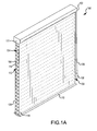
- the covering 100 may include a head rail 102, having a head tube or roller 126 (see Fig. 2A ) supporting a top edge of a panel 104, and an end rail110 supported by a bottom edge of the panel 104.
- the front sheet 118 may be connected at connection point 103 to the roller and at connection point 105 to the end rail and the rear sheet 120 may be connected at connection point 107 to the roller and at connection point 109 to the end rail.
- the head rail 102 may support the panel 104 over an architectural opening and thus may generally correspond to the shape and dimensions of the architectural opening.
- Fig. 1A is a perspective view of the panel 104 of the covering 100 extended with the cells in an open configuration.
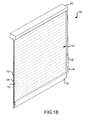
- Fig. 1B is a perspective view of the panel 104 of the covering 100 extended with the cells in a closed configuration.
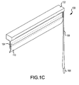
- Fig. 1C is a perspective view of the panel 104 of the covering 100 substantially retracted into the headrail 102.
- the covering 100 may also include a system for controlling the retraction, extension, and vane orientation when extended.
- the system may include in one example a control cord 106 and cord end pendant 108 for opening and closing cells 112 of the panel 104, as well as retracting and extending the panel 104 across the architectural opening.
- the system may also include a pulley about which the cord extends, the rotation of the pulley driving the rotation of the head tube.
- the pulley may be in a direct drive arrangement with the head tube, or may be connected through a gear train and/or clutch mechanism.
- the cord end 108 may provide weight to the control cord 106, in order to maintain the shape of the control cord 106.
- the cord end 108 may also take up additional material of the control cord 106 as the panel 104 is extend or retracted, so that the control cord 106 may remain at substantially the same length when the panel 104 is retracted or extended.
- the system for controlling the rotation of the head tube may include an electric motor which is controlled manually by a user, or through pre-programmed or programmable software control unit.
- control cord 106 and/or cord wand 108 may be operably associated with the panel 104 and may be substantially any type of controlling mechanism, e.g., endless loop cord, single cord, rotating wand, and so on.
- control cord 106 and/or the wand 108 are configured to move the panel 104 so as to open and close the cells 112 and move the end rail 110 upward and downward.
- the panel 104 may include a front sheet 118, a rear sheet 120, and cells 112 that span between the two sheets 118, 120.
- the cells 112 in the panel 104 are at least in part defined by a top vane 114 and a bottom vane 116.
- the top vane 114 and the bottom vane 116 may be interconnected together, and may each be connected to a front sheet 118 and a rear sheet 120.
- the interconnection between vanes 114, 116 and the front and rear sheets 118, 120 is discussed in more detail below with respect to Fig. 3 .
- Each cell then includes at least in part a set of coordinated vanes that move along with movement of either or both the front and rear sheets.
- the front sheet 118, the rear sheet 120, and the vanes 114, 116 may be substantially any type of material, such as but not limited to, knits, wovens, non-wovens, and so on. Additionally, the sheets 118, 120 and the vanes 114, 116 may have varying translucent properties, varying from blackout, opaque, to partially opaque, or clear. In some instances the sheets 118, 120 may have an increased light translucence as compared with the vanes, so that when the vanes 114, 116 are closed the light translucence of the covering may be varied.
- the sheets 118, 120 are displaced relative to one another in a direction orthogonal to the length of the vane (i.e. vertically relative to Fig. 1A ), the interior volume or cavity 122 of the cell changes.
- the sheets may be moved by a force that may be generally parallel to each of the sheets, such as an upward vertical force provided as the roller changes position.
- the interior volume, or cavity, of the cell is represented by the cross-sectional area of the interior of the cell.
- the covering is in the fully extended configuration, such as in Fig. 1A
- the cell defines a larger interior volume.
- Fig. 1A is an elevation view of the covering of Fig. 1A with the end cap removed to illustrate the roller, with the cells 112 in the open position.
- the motion of the sheets may be substantially parallel to one another (due to the force applied upwards by the roller), as the cells 112 collapse, the sheets 118, 120 may be moved horizontally closer together (See Figs. 5A-5C ).
- the vanes 114, 116 may be spaced apart from one another to define a cavity 122 therebetween. In this position, the vanes 114, 116 may extend so that portion of each vane 114, 116 may be at least partially perpendicular or angled to the front sheet 118 and the back sheet 120. In this configuration, the cell volume is relatively large.
- the vanes 114, 116 When the cells 112 are in the open configuration, the vanes 114, 116 may be spaced apart from the other group, or sets, of vanes 114, 116 to define gaps 124 between each cell 112. These gaps 124 may allow light to be transmitted uninterrupted through the gaps from the rear sheet 120 to the front sheet 118, especially in embodiments where the front sheet 118 and rear sheet 120 are both translucent.
- Fig. 2B is a side elevation of the covering of Fig. 1B with the end cap removed to illustrate the roller.
- the cells 112 are in an intermediate configuration between being fully open and fully closed, such as when transitioning from an open position to a closed position.
- the panel 104 may be oriented to extend from a front side of the roller 126 and thus may wind around a front side of the roller.
- the interior volume of the cells 112 decrease in size, as shown in Fig. 2B .
- the height gap 124 is reduced since the bottom edge 115 of an upper cell 117 is brought closer to a top edge of the adjacent lower cell. This is described in more detail below.
- Fig. 2C is a side elevation view of the covering of Fig. 1B with the end cap removed to illustrate the position of the roller.
- the cells 112 will continue to collapse until the interior volume 122 between the vanes 114, 116 in each cell is in its smallest configuration. In this configuration, the vanes 114, 116 of each cell 112 may be substantially parallel to the front sheet 118 and the rear sheet 120.
- the cavity 122 defined by the top vane 114 and the bottom vane 116 may be substantially eliminated.
- the gaps 124 may also be reduced and/or eliminated. This occurs because the open distance, Gopen (defined below with respect to Fig. 3 ) between a lower edge 119 of an adjacent upper cell and the upper edge 121 of a lower cell is eliminated, with the two edges 119, 121 possibly overlapping.
- the cells 112 may form a pseudo multilayer middle sheet positioned between the front and rear sheets 118, 120.
- the vanes 114, 116 may block light at least partially or substantially from being transmitted through the rear sheet 120 to the front sheet 118.
- the panel 104 when the covering 100 is retracted, the panel 104 may be wrapped around a roller 126. As the roller 126 rotates in a particular direction, the panel 104 is wound around the outer surface of the roller 126. To retract the panel 104, the roller 126 may wind in the opposite direction, unwrapping the panel 104.
- the roller 126 may turn a partial rotation, e.g., a quarter turn in order to sufficiently vertically displace the one of the sheets 118, 120 with respect to the other.
- the two sheets 118, 120 may be connected to the roller 126 and be spaced apart from one another, so as the roller 126 rotates, the sheets 118, 120 may be displaced with respect to each other because a height of one sheet 118, 120 may be varied with respect to the other sheet 118, 120 as the roller 126 is rotated.
- the connection points 103, 107 of the front sheet and rear sheet to the roller may change in position relative to one another.
- connection points 103, 107 may both be positioned at a bottom edge of the roller which is exposed through the headrail.
- the connection points 103, 107 may be partially offset from one another, with the front sheet 118 connection point 103 being located on a portion of the roller received within the head rail and the rear sheet 120 connection point 107 being positioned on the portion of the roller exposed in an aperture of the headrail.
- the front sheet connection point 103 may located further within the headrail, and the rear sheet connection point 107 may be closer towards a right side (relative to Fig. 2C ) of the headrail.
- the front sheet 118 and the rear sheet 120 may function as the operating elements to open and close the cells 112.
- the manufacturing process for the covering 100 may be simpler than conventional coverings including operable vanes.
- the vanes 114, 116 may be attached to the sheets 118, 120 without requiring placement of operating elements between the vanes 114, 116 and the sheets 118, 120.
- front sheet 118 and the rear sheet 120 may be displaced relative to each other in many other manners, and the aforementioned embodiments are meant as exemplary only. Similarly, the panel 104 may be retracted and extending in substantially any manner.
- the cells 112 for the covering 100 are formed at least in part by a set of two vanes, such as an upper, or top, vane 114 and a lower, or bottom, vane 116.
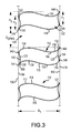
- Fig. 3 is an enlarged side elevation view of the covering 100 of Fig. 1A .
- Each cell 112 is a tube having sidewalls 123, 1255 that define a cavity 122, the cell 112 extending across the width of the covering 100.
- Each cell 112 is generally parallel to the cell adjacent above it and adjacent below it.
- Each cell 112 may be constructed of one piece of material integrally formed to define the sidewalls 123, 125 of a tube, separate strips, such as vanes 114, 116, attached together to define sidewalls 123, 125 of a tube, separate strips or vanes attached to the front and/or back sheets 118, 120 which together define sidewalls 123, 125 of a tube, or one piece of material attached to the front or back sheet which together define sidewalls of a tube.
- Fig. 3 shows an example of a panel construction where the cell 112 is positioned between a front sheet 118 and a rear sheet 120.
- the cell 112 defines an enclosed tube without requiring any portion of the front or rear sheets.
- the cell 112 may be constructed by one integral sheet of material formed into a tube, or two or more separate vanes attached together to form a tube.
- the cell 112 in this example is two vanes 114, 116 attached together, and defines two opposing apexes 132, 136, one adjacent the front sheet 118, and one adjacent the rear sheet 120.
- the top vane 114 spans between the front sheet 118 and the rear sheet 120.
- top vane 114 may extend substantially parallel to a back surface of the front sheet 118.
- the top vane 114 may have a crease 132 beak, apex, or tip at the top of the parallel portion to the front sheet 118.
- the top vane 114 may extend downward from the crease 132 and may be operably connected the front sheet 118 at a first front connection member 146.
- the first connection member 146 may be located either coextensively with the crease 132 or at a position below or above the crease 132.
- the top vane 114 extends downward to form a sidewall 154 that may be partially or substantially parallel to the front sheet 118.
- the sidewall 154 bends outwards towards the rear sheet 120 and is connected via a second front connection member 148 to the rear face 150 of the front sheet 118.
- the second front connection member 148 may be aligned with a bottom curve or bend point of the bottom vane 116.
- the sidewall 154 may have a slight curve such as an "S" shape as it transitions from the location of the first front connection member 146 to the location of the second front connection member 148. Further, as shown in Fig. 3 , the top vane 114 sidewall 154 transitions to form the bottom vane 116 at or after the location of the second front connection member 148.
- the bottom vane 116 may be connected at the location of the second front member 148 and may curve outward and transition away from the front sheet 118 at the bend point 140.
- the bottom vane 116 extends horizontally from the front sheet 118 to connect to the rear sheet 120.
- the bottom vane 116 may have two bends or curves 138, 140 that are curved in opposite directions.
- the first bend point 140 extends the bottom vane 116 downward towards the end rail 110 and the second bend point 138 extends the bottom vane 116 upward towards the head rail 102.
- the bottom vane 116 may be shaped as an "S" or other curved shape.
- the bottom vane 116 transitions into the bottom crease 136, or point.
- the bottom crease 136 may be directed towards the end rail 110, and may be oppositely positioned with respect to the crease 132 of the top vane 114. Similar to the crease 132 of the top vane 114, the bottom vane 116 may be connected to the rear sheet 120 (via a second rear connection member 144) adjacent to or coextensive with the crease 136.
- the bottom vane 116 transitions upwards from the crease 136, forming a rear sidewall 152.
- the rear sidewall 152 may be substantially parallel to the rear sheet 120 and may have a corresponding shape to the front sidewall 154.
- the rear sidewall 152 is operably connected to the inner surface 156 of the rear sheet 120 via a first rear connection member 142.
- the first rear connection member 142 may be located near a transition between the bottom vane 116 and the top vane 114.
- the bottom vane 116 curves at bend point 134, transitioning into the top vane 114.
- the top vane 114 extends between the two sheets 118, 120 and curves at a second bend point 130 to transition to the crease 132.
- top vane 114 and the bottom vane 116 may be complementarily shaped, and the two vanes 114, 116 may generally trace the overall shape of each other. In this manner the bend or inflection points of each vane 114, 116 may be aligned and curved in the same direction.
- This complementary structure may allow the top vane 114 and the bottom vane 116 to be compressed into each other, e.g., when the cells 112 are closed as shown in Fig. 5C .
- the vanes may be 114, 116 heat set and folded, which may determine the open shape of the cell 112.
- the vanes 14, 116 may extend away from the attachment locations to the sheets 118, 120 at large or narrow departure angles, depending on whether the vanes 114, 116 include creases are heat set and folded or just attachment points without a separate heat set or otherwise permanent or semi-permanent crease formed therein.
- the vanes 114, 116 may include fabric stiffeners to provide for a desired cell 112 shape substantially without sag in the open configuration.
- the vanes 114, 116 may include fibers, or may be an at least partially rigid material that may maintain its shape or may be at least partially resilient so that it may return to its original shape after deformation.
- connection members 142, 144, 146, 148 operably couple the vanes 114, 116 to the sheets 118, 120 so that as the sheets 118, 120 move the vanes 114, 116 may move correspondingly.
- the connection members 142, 144, 146, 148 may be substantially any type of connecting component, such as but not limited to, adhesive, fasteners, sewing, hook and loop, and so on.
- the connection members 142, 144, 146, 148 may extend across the entire width of the respective front sheet 118 or rear sheet 120. In this manner, the vanes 114, 116 may be operably connected to the sheets 118, 120 substantially along their entire width.
- connection members 142, 144, 146, 148 may be spaced apart from each other at varying distances.
- the distance each connection member 142, 144, 146, 148 is spaced apart may determine the opening and closing characteristics of the cells 112, as well as the shape of the cells 112. For example, the spacing may determine the size of the cavity of the cells, as well as the size of the gaps defined between each of the cells.
- the first front connection member 146 and the second front connection member 148 may be positioned on the back surface 150 of the front sheet 118 at a height of H1 from each other.
- the first rear connection member 142 and the second rear connection member 144 may be spaced apart from each other on the back sheet 120 by a height of H2 from each other.
- the heights H1 and H2 may be substantially the same so that the vanes 114, 116 in the open position may span substantially horizontally between the two sheets 118, 120 or the heights H1 and H2 may be different and the vanes 114, 116 may be angled in spanning between the front sheet 119 and the rear sheet 120.
- the heights H1 and H2 may be varied depending on the desired volume of the cavity 122 of the cell 112 and/or the height of the cells 112. Further, in some embodiments, the top vane 114 and/or the bottom vane 116 may be interconnected to a respective sheet 118, 120 along the entire heights H1 and H2. In other words the first and second connection members may be combined forming a single connection member. However, in these embodiments, the cell 112 may be more rigid than in embodiments with two separate connection locations.
- the first front connection member 146 may be spaced apart from the second rear connection member 144 by a height of H3.
- the height H3 varies as the cells 112 are opened and closed. This transition and height variation will be discussed in more detail below with respect to Figs. 5A-5C .
- the interconnection of the vanes 114, 116 and the connection of the vanes 114, 116 to the sheets 118, 120 forms the cells 112 for the panel 104.
- the cell 112 structure of the vanes 114, 116 provides insulation from a first side of the covering 100 to a second side of the covering 100.
- the cells 112 trap pockets of air in the cavities 122, which acts as a buffer to provide insulation.
- a temperature of an environment on the rear side of the panel 104 may not affect the temperature of an environment on the front side of the panel 104.
- the cells 122 may trap air preventing cold air from a first side of the window that may be exposed to outside elements from decreasing the temperature of air on the front side of the window.
- the cells 112 may be positioned apart from each other by a gap 124.
- the gaps 124 formed between cells 112 may also act to trap air and provide further insulative properties to the covering 100.
- the gaps 124 may have a height Gopen (e.g., when the panel is in the open configuration shown in Fig. 2A ).
- the height Gopen may be defined as the height between the bottom apex or crease 136 or lowermost point of an upper cell and the upper apex of crease 132 of an adjacent lower cell or the upper most point of the lower cell.
- the height Gopen may define the height of light rays which may be transmitted through the front sheet 118 and rear sheet 120 between the cells 112. Accordingly, as the height Gopen between the cells changes, so amount of does the amount of light rays which can be transmitted through the covering 100 without encountering the material of the cells, i.e., pass only through the front sheet 118 and rear sheet 120.
- the insulative characteristics of the covering 100 provide multiple features from a single covering.
- the vanes 114, 116 are spaced apart from each to define a cavity 122 therebetween, see, e.g., Fig. 3 .
- each cell 112 defined by the vanes 114, 116 is spaced apart from adjacent cells 112, defining gaps 124 between each row of cells 112.
- the vanes 114, 116 may be adjacent one another or may be in contact with at portion of the other vane 114, 116.
- the cavity 122 may be substantially reduced, as well as the gaps 124 between the cells 112, in some instances the height Gopen may be completely reduced so that there may be very little (if any) distance between the bottom apex 136 or lowermost point of an upper cell and the upper apex 132 or uppermost point of an adjacent lower cell, see for example, Fig. 5C .
- the vanes 114, 116 may be strips of an at least partially flexible material interconnected to the sheets 118, 120 horizontally along a width of the panel 104.
- the vanes 114, 116 may be flexible yet rigid.
- the vanes 114, 116 should be flexible enough so that they may be compressed to a substantially flat position without being damaged, e.g., see Fig. 2C ; yet, be rigid enough so that they may maintain their shape when the cells 112 are open, see, e.g., Fig. 2A .
- Fig. 4A is a side elevation view of a covering 200 including only a single vane 210.
- the vane 210 is connected to the front sheet 218 at via a first adhesive 212 and to the rear sheet 120 via a second adhesive 214.
- the adhesive 212, 214 secures the vane 210 to the two sheets 218, 220.
- the light may be transmitted through the rear sheet 120 and the adhesive 214 blocks part of the light; however, other light rays may pass through the rear sheet 220 without be blocked.
- the light blocked by the adhesive 214 may form a shadow 216.
- the shadow 216 may be transmitted to the front sheet 218 and may be visible on the front side of the covering.
- the shadow 216 may appear black or and darkened portions or spots of the front side of the covering 200, which may be aesthetically unpleasing. Additionally, the spots may cause the material of the front sheet 218 to fade unevenly due to light exposure.
- the covering 100 of the present disclosure may eliminate darkened spots due to shadows.
- Fig. 4B is an enlarged side elevation view of the covering 100 being exposed to light.
- a shadow 216 may be created as light is blocked by the first rear connection member 142, which may include adhesive
- the shadow 216 may be diffused by the bottom vane 116.
- the bottom vane 116 may substantially reduce the appearance of the shadow 216 and may therefore create a diffused shadow 230.
- the diffused shadow 230 may not reach the front sheet 118, thus preventing darkened spots or portions to appear on the front sheet 118.
- the shadow may be so attenuated that it may not create a darkened spot on the front side of the covering 100.
- the covering 100 may have substantially even fading, as compared with the covering 200 of Fig. 4A , as well as may be more aesthetically appealing.
- the cells 112 may be opened and closed by varying a spacing distance D1 between the front sheet 118 and the rear sheet 120, as well changing the relative heights or orientation of the sheets 118, 120 with respect to each other. For example, as shown in Fig. 3 , when the cells 112 are completely open the sheets 118, 120 may be spaced apart from each other by a distance D1.
- the distance D1 may correspond to a horizontal width of the vanes 114, 116 that spans between the two sheets 118, 120.
- movement of the sheets 118, 120 relative to each other may be accomplished by the control cord 106 and the head rail 102 and/or end rail 110.
- the sheets 118, 120 may move vertically generally parallel with respect to the second sheet, which may be accomplished in substantially any manner.
- the opening and closing of the cells 112 will be described herein as moving the front sheet 118 with respect to the rear sheet 120.
- the rear sheet may be moved as well or instead of moving the front sheet, see, for example, Figs. 12A-12C . Accordingly, the foregoing discussion is meant as exemplary only.
- Fig. 5A is a side elevation view of the cells 112 in a mostly open configuration as the cells 112 transition from open to closed.
- the front sheet 118 may remain substantially in its original position.
- the vanes 114, 116 are pulled downwards with the rear sheet 120, pulling the sheets 118, 120 closer to each other because the vanes 114, 116 are connected to each sheet 118, 120.
- the distance D2 that separates the sheets 118, 120 when the cells 112 are mostly open is less than the distance D1 separating the sheets 118, 120 when the cells 112 are fully open.
- the force downward may be applied generally parallel to the two sheets, as the sheets shift vertically relative to one another, the vanes provide a horizontal force pulling the sheets closer together. This horizontal force is due to the vertical shifting of the connection points of the vanes, discussed in more detail below.
- the height between the first front connection member 146 and the second rear connection member 144 is extended to a height H4.
- the height H4 may be larger than the height H3, as the vanes 114, 116 transition from a relatively perpendicular orientation with respect to the sheets 118, 120 to an angled orientation.
- Fig. 5B is a side elevation view of the cells 112 in a partially closed configuration as the cells 112 transition from open to closed. If the rear sheet 120 continues to experience a downwards force F, the distance between the sheets 118, 120 reduces to distance D3. Additionally, the height between the first front connection member 146 and the second rear connection member 144 increases to a height of H5. The vanes 114, 116 thus transition so as to be substantially parallel to the sheets 118, 120, and the cavity 122 reduces in volume as the cells 112 collapse.
- Fig. 5C is a side elevation view of the cells 112 in a substantially closed configuration.
- the sheets 118, 120 may then be positioned substantially adjacent each other and separated by a distance D4, which may be significantly less than the open distance D1.
- the distance D4 may be substantially zero, that is the sheets 118, 120 may be substantially in contact with each other.
- the first front connection member 146 may be separated from the second rear connection member 144 by a height H6, which may be larger than the other heights separating the two connection members 144, 146.
- the vanes 114, 116 may be positioned substantially parallel to the sheets 118, 120, as shown in Fig. 5C . Further, as the vanes 114, 116 are substantially parallel with the sheets 118, 120, the cell cavities 122 may be substantially collapsed, collapsing the cells 112. In the configuration shown in Fig. 5C , the height Gopen between the lowermost apex 136 of the upper cell and the uppermost apex 132 of the adjacent lower cell may be substantially, if not completely, reduced, so that little to no light may be transmitted through the panel 104 without being transmitted through the material of the cells 112.
- the panel 104 may be retraced around the roller 126.
- the collapsed or closed configuration of the cells 112 allows the panel 104 to be rolled without damaging the shape of the vanes 114, 116 and thus the cells 112.
- the covering 100 provides insulation, varying light transmission, as well as a rolled storage or retracted configuration.
- the cells 112 of the covering 100 may be formed in different shapes, and the connection members and locations between the vanes 114, 116 and the sheets 118, 120 may be altered. As discussed above, the cells 112 may be formed of two interconnected vanes, a single piece of material folded and interconnected to itself, or multiple sheets of material. In one example, the vanes 114, 116 may be connected to each sheet 118, 120 at a single location.
- Fig. 6 is a side elevation view of an exemplary cell 112 where the vanes 114, 116 are connected to the front sheet 118 and the rear sheet 120, respectively, by a connection member 244, 246.
- the creases 132, 134 forming the upper and bottom tips of the vanes 114, 116, receptively, may be free or unattached from the sheets 118, 120.
- the creases 132, 136 may be set into the material forming the vanes 114, 116 (e.g., heat or chemically folded) so that they may be at least partially rigid to retain the bend point.
- the cells 112 may be substantially more flexible that in other embodiments.
- the shape of the cells 112 may be differently configured.
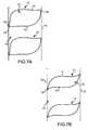
- Figs. 7A and 7B illustrate alternative cell shapes.
- the vanes 114, 116 may be less "S" shaped and have a more "C" shape, in other words, the curves may be less defined than the cell 112 of Fig. 3 .
- the vanes 114, 116 may have an increased departure angle away from the sheets 118, 120.
- the cavity 122 may be larger, trapping more air and providing increased insulation as compared with the cells 112 of Fig. 3 .
- the vanes 114, 116 may block more light that may be transmitted through the gaps 124, as the gaps 124 may be smaller.
- the cell 112 may have a narrower cavity 122 formed from a small departure angle as the vanes 114, 116 transition away from connection points to the sheets 118, 120.
- the vanes 114, 116 may provide less insulation than the cell shape of Fig. 7A .
- more light may be transmitted through the covering 100 (if clear or high transmissive materials are used for the sheets 118, 120) because the cells 112 may have a reduced height compared with the cells of Fig. 7A .
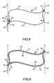
- the cells 112 may be created by a single piece of material or by multiple pieces of material connected together.
- Fig. 8 illustrates an exemplary cell 112 formed by a material overlapped on itself and connected together.
- the bottom vane 116 partially overlaps a terminal edge 256 of the top vane 114. Rather than being connected together, the terminal edge 256 of the top vane 114 is received within a tab 300 of the bottom vane 116.
- the top vane 114 is connected to the bottom vane via a connection member 54.
- the vane connection member 254 may be substantially similar to the connection members 142, 144, 146, 148 and the vane connection member 254 may be adhesive, hook and loop, or other fastener.
- the tab 300 may be operably connected to the inner surface 156 of the rear sheet 120 by the connection member 144.
- a free end 258 of the tab 300 may extend past both the connection member 144 and the vane connection member 254.
- the cells 112 may include multiple layers.
- the insulation properties of the panel 104 may be increased as air may be more securely received within the cavity 122.
- Fig. 9 is an enlarged view of a single cell 112 formed by overlapping material over itself and connected.
- the top vane 114 and the bottom vane 116 may each have a first or outer layer 304 and a second or inner layer 306.
- the two layers combine to form each vane 114, 116.
- the material is connected together by the connection member 302.
- the connection member 302 location is shown as being located at the bottom crease 136; however, it may be positioned at substantially any other location.
- the two layers 304, 306 may be formed by connecting two separate pieces of material to each other.
- Fig. 10 is an enlarged side elevation view of the cell 112 including the two layers 304, 306.
- the two layers are connected by a second connection member 308 in addition to the connection member 302 shown in the cell 112 of Fig. 9 .
- the second connection member 308 is located in the crease 132.
- the cell 112 may be connected together by the first connection member 302 in the crease 136 and by the second member 308 at the crease 136.
- connection locations are possible as well, and the locations illustrated in Figs. 9 and 10 are exemplary only.
- the cells 112 may be formed from two separate pieces of material that are connected to the sheets 118, 120.
- Fig. 11 is an enlarged side elevation view of a cell 112 formed by two disconnected vanes 114, 116.
- the cell 112 may not be fully enclosed, as the vanes 114, 116 may be not directly connected together, and the sheets 118, 120 may form a portion of a front and rear wall of the cells 112.
- the top vane 114 may have a first free end 349 operably connected to the first front connection member 142 and a second free end 351 that extend downwards past the first rear connection member 146 forming a flap 357 or tab.
- the flap 357 may at least partially extend downwards from the first rear connection member 146 towards the second rear connection member 146.
- the flap 357 may be at least partially parallel to a portion of the rear sheet 120 or may be otherwise angled to extend downwards towards the second front connection member 148.
- the bottom vane 116 may be substantially similar to the top vane 114, but may positioned in an opposite manner. That is, the bottom vane 116 may include two free ends 353, 355, with the first free end 353 extending upwards from the second front connection member 144 towards the first front connection member 142. In this manner, the bottom vane 116 may include a flap 352 or tab that may form a portion of a front wall of the cell 112. The second free end 355 may be operably connected to the rear sheet at the second rear connection member148.
- the two flaps 352, 357 of the vanes 114, 116 may substantially form the rear and front walls of the cell 112, as they extend substantially the entire length of the sheets 118, 120 between the first connection members 142, 146 and the second connection members 144, 148. In other words, there may be a minimal distance, if any, between the flap 357 of the top vane 114 and the second rear connection member 148 and the flap 353 of the bottom vane 116 and the first front connection member 142.
- the flaps 352, 357 may be at an at least partially rigid material or may include a component such as fibers or pressure sensitive adhesive that may provide additional rigidity to allow the flaps 352, 357 to support themselves and maintain a desired shape.
- the cell 112 may be substantially enclosed by the vanes 114, 116. However, in other instances, the flaps 352, 357 may define a gap and terminate prior to the first front connection member 142 or the second rear connation member 148, respectively. In these instances, the cell 112 may be at least partially defined by the front and rear sheets 118, 120. That is, the front and rear sheets 118, 120 may form a portion of the front and rear walls of the cells.
- the covering 100 may be oriented to allow light to be admitted through the gaps 124 or spaces between the cells 112.
- Fig. 12A is a side elevation view of another example of the covering of Fig. 1A with an end cap removed from the head rail.
- Fig. 12B is a side elevation view of another example of the covering of Fig. 1A as the cells transition from open to closed.
- Fig. 12C is a side elevation view of another example of the covering of Fig. 1B with the end cap removed.
- the panel 104 may extend off of a rear side of the roller 126.
- the rear sheet 120 may support the top end of the cells 112 whereas the front sheet 118 may support the bottom end of the cells 112.
- the orientation of the panel 104 onto the roller 126 as shown in Figs. 12A-12C allows light (e.g., from the sun) to enter through the front sheet 118 through the gaps 124.
- light entering through the rear sheet 120 may be blocked from exiting through the front sheet 118 by the vanes 114, 116. This is because in the example illustrated in Figs. 2B and 2C , as the cells 112 are closed, the top end of the cells 112 may be operably connected to the front sheet 118, such that the cells 112 extend from the front sheet 118 downward towards the rear sheet 120. Accordingly, light entering the panel 104 through the rear sheet 120 may encounter the cell 112 material for one or more cells 112, which as discussed with respect to Fig. 4B may diffuse light.
- the rear sheet 120 may be vertically displaced with respect to the front sheet 118. As this occurs, the interior volume of the cells 112 decrease in size, as shown in Fig. 12B .
- the ends of each of the vanes 114, 116 connected to the rear sheet are moved upwards relative to the front sheet 118 and the vanes 114, 116 extend downwards from the rear sheet 120 to connect with the front sheet 118 (opposite of the example illustrated in Figs. 2A-2C ).
- This vane orientation allows light from a light source (such as the sun) to be transmitted through the gaps 124 without substantially being blocked.
- the cells 112 may allow light through the panel 104 even as they transition from an open position to a closed position.
- the vane material may provide privacy.
- the front and rear sheets may be translucent or sheet material, whereas the vanes 114, 116 may be a non-translucent or less translucent material.
- the vanes 114, 116 may be oriented vertically to reduce visibility through the panel 104. Due to the orientation of the top ends of the cells 112, the cells 112 may still allow light to be transmitted through the gaps 124.
- privacy may be enhanced as compared to an open position, but the amount of light transmitted through the panel 104 may be substantially the same or only slightly attenuated.
- the panel 104 may be oriented such that the rear sheet 120 may increase vertically relative to the front sheet 118 to close the cells 112. This orientation and cell transition may allow light to be transmitted through gaps 124 defined between the cells 112, but may still provide for privacy as the vanes may block (or obscure) visibility through the panel 104.
Landscapes
- Engineering & Computer Science (AREA)
- Structural Engineering (AREA)
- Architecture (AREA)
- Civil Engineering (AREA)
- Blinds (AREA)
- Finishing Walls (AREA)
- Tents Or Canopies (AREA)
- Operating, Guiding And Securing Of Roll- Type Closing Members (AREA)
- Roof Covering Using Slabs Or Stiff Sheets (AREA)
Abstract


Description
- This application claims the benefit, under 35 U.S.C. § 119(e), of
U.S. provisional application number 61/727,838 - The present disclosure relates generally to coverings for architectural openings, and more specifically, to retractable coverings for architectural openings.
- Coverings for architectural openings, such as windows, doors, archways, and the like have assumed numerous forms over the years. Early forms for such coverings consisted primarily of fabric draped across the architectural opening, and in some instances, the fabric was not movable between extended and retracted positions relative to the opening. Some newer versions of coverings may include cellular shades. These shades include horizontally disposed collapsible tubes that are vertically stacked and secured on top of one another to form a panel of tubes. The cellular tubes may trap air to help provide insulation. The stacked configuration provides insulation but can be difficult to manufacture, as rows of cells must be created that are aligned with one another.
- Many cellular shades are retracted and extended by lifting or lowering, respectively, the lowermost cell. As the lowermost cell is lifted it compresses against the other cells, collapsing them on top of one another; and, as the lowermost cell is lowered, lowermost cell pulls the cells open. When in a retracted position, typical cellular shades are stored in a stacked configuration, i.e., one cell on top of the other cells in a vertical line. This retracted configuration is required for some cellular shades as wrapping the cells around a head rail may damage the cells and prevent the cells from opening.
- Additionally, most cellular shades do not provide for varying light transmission therethrough. Rather, typically a cellular shade has to be retracted or extended in order to vary the light transmission through the covering. However, in some instances, it may be desirable to vary the light, without retracting the panel, e.g., a covering for a bedroom window.
- Examples of embodiments described herein may take the form of a covering for an architectural opening. The covering may include a head rail, an end rail and a panel spanning between the head rail and the end rail. The panel may include a front sheet, a rear sheet operably coupled to the front sheet, and a cell spanning between the front sheet and the rear sheet. When the first sheet is at a first position relative to the rear sheet the cell is open and when the first sheet is at a second position relative to the rear sheet the cell is closed.
-
-
Fig. 1A is a perspective view of a covering for an architectural opening in the extended position with the cells in an open configuration. -
Fig. 1B is a perspective view of the covering in the extended position with the cells in a closed configuration. -
Fig. 1C is a perspective view of the covering in a retracted position. -
Fig. 2A is a side elevation view of the covering ofFig. 1A with an end cap removed from the head rail. -
Fig. 2B is a side elevation view of the covering ofFig. 1A as the cells transition from open to closed. -
Fig. 2C is a side elevation view of the covering ofFig. 1B with the end cap removed. -
Fig. 3 is an enlarged side elevation view of a cellular panel of the covering ofFig. 1A . -
Fig. 4A is a side elevation view of a covering having a single vane with shadows being transmitted therethrough. -
Fig. 4B is a side elevation view of the covering ofFig. 1A illustrating shadows being diffused through the cell structure of one example of the present invention. -
Fig. 5A is an enlarged side-elevation view of the cellular panel inFig. 2A . -
Fig. 5B is an enlarged side elevation view of the cellular panel ofFig. 2B . -
Fig. 5C is an enlarged side elevation view of the cellular panel ofFig. 2C . -
Fig. 6 is an enlarged side elevation view of a second example of a cell for the covering ofFig. 1A . -
Fig. 7A is an enlarged side elevation view of a third example of a cell for the covering ofFig. 1A . -
Fig. 7B is an enlarged side elevation view of a fourth example of a cell for the covering ofFig. 1A . -
Fig. 8 is an enlarged side elevation view of a fifth example of a cell for the covering ofFig. 1A . -
Fig. 9 is an enlarged side elevation view of a sixth example of a cell for the covering ofFig. 1A . -
Fig. 10 is an enlarged side elevation view of a seventh example of a cell for the covering ofFig. 1A . -
Fig. 11 is an enlarged side elevation view of an eighth example of a cell for the covering ofFig. 1A . -
Fig. 12A is a side elevation view of another example of the covering ofFig. 1A with an end cap removed from the head rail. -
Fig. 12B is a side elevation view of another example of the covering ofFig. 1A as the cells transition from open to closed. -
Fig. 12C is a side elevation view of another example of the covering ofFig. 1B with the end cap removed. - Some embodiments described herein may take the form of a covering for an architectural opening including operable vanes that also form insulative cells. The covering may include a front sheet and a rear sheet. One or more cells span between the two sheets, connecting the two sheets together. The covering may be retracted and extended to cover an architectural opening. This may allow the panel, including the cells, to be wound around a roller, reducing a retracted height of the covering. Further, the cells may be opened and closed, and depending on the material(s) used in the covering, opening and closing of the cells may vary the light transmissivity of the covering.
- When the cells are closed, each cell may be substantially compressed and the material forming each cell may be substantially parallel with each of the sheets. In some embodiments, a length or body of each of the cells may be adjacent to each other or partially overlap so that the cells may form a pseudo middle sheet positioned between the front and rear sheets. When the cells are open to at least some extent, each cell may be at least partially perpendicular or angled with respect to at least one of the sheets. In an open configuration, the cells may then provide insulation by trapping air in each cell, as well as between adjacent sets of cells. Further, the cells may reduce or diffuse shadows created by the structure of the covering on one side from being as noticeable on the other side of the covering. In other words, shadow lines due to light encountering the shade on the outer side thereof, whether or not at a particular angle of incidence, may be reduced as viewed from the interior side of the covering.
- The covering as disclosed herein may be used to cover substantially any type of architectural opening, such as but not limited to, windows, door frames, archways, and the like. Referring generally to
Figs. 1A-1C , the covering 100 may include ahead rail 102, having a head tube or roller 126 (seeFig. 2A ) supporting a top edge of apanel 104, and an end rail110 supported by a bottom edge of thepanel 104. For example, thefront sheet 118 may be connected atconnection point 103 to the roller and atconnection point 105 to the end rail and therear sheet 120 may be connected atconnection point 107 to the roller and atconnection point 109 to the end rail. Thehead rail 102 may support thepanel 104 over an architectural opening and thus may generally correspond to the shape and dimensions of the architectural opening.Fig. 1A is a perspective view of thepanel 104 of the covering 100 extended with the cells in an open configuration.Fig. 1B is a perspective view of thepanel 104 of the covering 100 extended with the cells in a closed configuration.Fig. 1C is a perspective view of thepanel 104 of the covering 100 substantially retracted into theheadrail 102. - The covering 100 may also include a system for controlling the retraction, extension, and vane orientation when extended. The system may include in one example a
control cord 106 andcord end pendant 108 for opening and closingcells 112 of thepanel 104, as well as retracting and extending thepanel 104 across the architectural opening. As is known, the system may also include a pulley about which the cord extends, the rotation of the pulley driving the rotation of the head tube. The pulley may be in a direct drive arrangement with the head tube, or may be connected through a gear train and/or clutch mechanism. In one example, thecord end 108 may provide weight to thecontrol cord 106, in order to maintain the shape of thecontrol cord 106. Thecord end 108 may also take up additional material of thecontrol cord 106 as thepanel 104 is extend or retracted, so that thecontrol cord 106 may remain at substantially the same length when thepanel 104 is retracted or extended. Additionally, the system for controlling the rotation of the head tube may include an electric motor which is controlled manually by a user, or through pre-programmed or programmable software control unit. - It should be noted that the
control cord 106 and/orcord wand 108 may be operably associated with thepanel 104 and may be substantially any type of controlling mechanism, e.g., endless loop cord, single cord, rotating wand, and so on. In many embodiments, thecontrol cord 106 and/or thewand 108 are configured to move thepanel 104 so as to open and close thecells 112 and move theend rail 110 upward and downward. - The
panel 104 may include afront sheet 118, arear sheet 120, andcells 112 that span between the twosheets cells 112 in thepanel 104 are at least in part defined by atop vane 114 and abottom vane 116. Thetop vane 114 and thebottom vane 116 may be interconnected together, and may each be connected to afront sheet 118 and arear sheet 120. The interconnection betweenvanes rear sheets Fig. 3 . Each cell then includes at least in part a set of coordinated vanes that move along with movement of either or both the front and rear sheets. - The
front sheet 118, therear sheet 120, and thevanes sheets vanes sheets vanes - To open and close the
cells 112, thesheets Fig. 1A ), the interior volume orcavity 122 of the cell changes. In other words, the sheets may be moved by a force that may be generally parallel to each of the sheets, such as an upward vertical force provided as the roller changes position. For clarity herein, as described, the interior volume, or cavity, of the cell is represented by the cross-sectional area of the interior of the cell. For instance, when the covering is in the fully extended configuration, such as inFig. 1A , the cell defines a larger interior volume. Assheets vane sheets Fig. 1B ), at which point the cell is considered "collapsed" or closed, and the panel is prepared for retraction into the head rail (SeeFig. 1C ).Fig. 2A is an elevation view of the covering ofFig. 1A with the end cap removed to illustrate the roller, with thecells 112 in the open position. In these instances, although the motion of the sheets may be substantially parallel to one another (due to the force applied upwards by the roller), as thecells 112 collapse, thesheets Figs. 5A-5C ). When thecells 112 are in an open configuration, thevanes cavity 122 therebetween. In this position, thevanes vane front sheet 118 and theback sheet 120. In this configuration, the cell volume is relatively large. - When the
cells 112 are in the open configuration, thevanes vanes gaps 124 between eachcell 112. Thesegaps 124 may allow light to be transmitted uninterrupted through the gaps from therear sheet 120 to thefront sheet 118, especially in embodiments where thefront sheet 118 andrear sheet 120 are both translucent. -
Fig. 2B is a side elevation of the covering ofFig. 1B with the end cap removed to illustrate the roller. InFig. 2B thecells 112 are in an intermediate configuration between being fully open and fully closed, such as when transitioning from an open position to a closed position. In the example illustrated inFig. 2B , thepanel 104 may be oriented to extend from a front side of theroller 126 and thus may wind around a front side of the roller. As thefront sheet 118 and/orrear sheet 120 is vertically displaced with respect to the other sheet, the interior volume of thecells 112 decrease in size, as shown inFig. 2B . In this configuration, theheight gap 124 is reduced since thebottom edge 115 of anupper cell 117 is brought closer to a top edge of the adjacent lower cell. This is described in more detail below. -
Fig. 2C is a side elevation view of the covering ofFig. 1B with the end cap removed to illustrate the position of the roller. When therear sheet 120 or thefront sheet 118 continues to be displaced with respect to the other, thecells 112 will continue to collapse until theinterior volume 122 between thevanes vanes cell 112 may be substantially parallel to thefront sheet 118 and therear sheet 120. Whencells 112 are in this closed configuration, thecavity 122 defined by thetop vane 114 and thebottom vane 116 may be substantially eliminated. - When the
cells 112 are closed, thegaps 124 may also be reduced and/or eliminated. This occurs because the open distance, Gopen (defined below with respect toFig. 3 ) between alower edge 119 of an adjacent upper cell and theupper edge 121 of a lower cell is eliminated, with the twoedges cells 112 may form a pseudo multilayer middle sheet positioned between the front andrear sheets vanes rear sheet 120 to thefront sheet 118. A more detailed description of the movement of thevanes cells 112 while thepanel 104 is retracted or extended is discussed below with respect toFigs. 5A-5C . - Referring briefly to
Figs. 1C and2C , when the covering 100 is retracted, thepanel 104 may be wrapped around aroller 126. As theroller 126 rotates in a particular direction, thepanel 104 is wound around the outer surface of theroller 126. To retract thepanel 104, theroller 126 may wind in the opposite direction, unwrapping thepanel 104. - To open or close the
cells 112, theroller 126 may turn a partial rotation, e.g., a quarter turn in order to sufficiently vertically displace the one of thesheets sheets roller 126 and be spaced apart from one another, so as theroller 126 rotates, thesheets sheet other sheet roller 126 is rotated. As can be seen inFigs. 2A-2C , as the roller rotates, the connection points 103, 107 of the front sheet and rear sheet to the roller may change in position relative to one another. InFig. 2A the connection points 103, 107 may both be positioned at a bottom edge of the roller which is exposed through the headrail. InFig. 2B the connection points 103, 107 may be partially offset from one another, with thefront sheet 118connection point 103 being located on a portion of the roller received within the head rail and therear sheet 120connection point 107 being positioned on the portion of the roller exposed in an aperture of the headrail. And, inFig. 2C the frontsheet connection point 103 may located further within the headrail, and the rearsheet connection point 107 may be closer towards a right side (relative toFig. 2C ) of the headrail. - The
front sheet 118 and therear sheet 120 may function as the operating elements to open and close thecells 112. Thus, the manufacturing process for the covering 100 may be simpler than conventional coverings including operable vanes. For example, in creating thepanel 104, thevanes sheets vanes sheets - It should be noted that the
front sheet 118 and therear sheet 120 may be displaced relative to each other in many other manners, and the aforementioned embodiments are meant as exemplary only. Similarly, thepanel 104 may be retracted and extending in substantially any manner. - As briefly described above, the
cells 112 for the covering 100 are formed at least in part by a set of two vanes, such as an upper, or top,vane 114 and a lower, or bottom,vane 116.Fig. 3 is an enlarged side elevation view of the covering 100 ofFig. 1A . Eachcell 112 is atube having sidewalls 123, 1255 that define acavity 122, thecell 112 extending across the width of thecovering 100. Eachcell 112 is generally parallel to the cell adjacent above it and adjacent below it. Eachcell 112 may be constructed of one piece of material integrally formed to define thesidewalls vanes sidewalls sheets sidewalls -
Fig. 3 shows an example of a panel construction where thecell 112 is positioned between afront sheet 118 and arear sheet 120. Thecell 112 defines an enclosed tube without requiring any portion of the front or rear sheets. Thus thecell 112 may be constructed by one integral sheet of material formed into a tube, or two or more separate vanes attached together to form a tube. Thecell 112 in this example is twovanes apexes front sheet 118, and one adjacent therear sheet 120. With continued reference toFig. 3 , thetop vane 114 spans between thefront sheet 118 and therear sheet 120. As thetop vane 114 approaches thefront sheet 118, it may extend substantially parallel to a back surface of thefront sheet 118. Thetop vane 114 may have acrease 132 beak, apex, or tip at the top of the parallel portion to thefront sheet 118. Thetop vane 114 may extend downward from thecrease 132 and may be operably connected thefront sheet 118 at a firstfront connection member 146. Thefirst connection member 146 may be located either coextensively with thecrease 132 or at a position below or above thecrease 132. - After the location of the
first connection member 146, thetop vane 114 extends downward to form asidewall 154 that may be partially or substantially parallel to thefront sheet 118. Thesidewall 154 bends outwards towards therear sheet 120 and is connected via a secondfront connection member 148 to therear face 150 of thefront sheet 118. The secondfront connection member 148 may be aligned with a bottom curve or bend point of thebottom vane 116. In one example, thesidewall 154 may have a slight curve such as an "S" shape as it transitions from the location of the firstfront connection member 146 to the location of the secondfront connection member 148. Further, as shown inFig. 3 , thetop vane 114sidewall 154 transitions to form thebottom vane 116 at or after the location of the secondfront connection member 148. - As the top and
bottom vanes bottom vane 116 may be connected at the location of the secondfront member 148 and may curve outward and transition away from thefront sheet 118 at thebend point 140. Thebottom vane 116 extends horizontally from thefront sheet 118 to connect to therear sheet 120. As thebottom vane 116 approaches therear sheet 120, it curves upward towards thehead rail 102 atbend point 138, in an opposite direction from thebend point 140. In one example, thebottom vane 116 may have two bends or curves 138, 140 that are curved in opposite directions. In other words, thefirst bend point 140 extends thebottom vane 116 downward towards theend rail 110 and thesecond bend point 138 extends thebottom vane 116 upward towards thehead rail 102. In this manner, thebottom vane 116 may be shaped as an "S" or other curved shape. - At the bottom portion of the
second bend point 138, thebottom vane 116 transitions into thebottom crease 136, or point. Thebottom crease 136 may be directed towards theend rail 110, and may be oppositely positioned with respect to thecrease 132 of thetop vane 114. Similar to thecrease 132 of thetop vane 114, thebottom vane 116 may be connected to the rear sheet 120 (via a second rear connection member 144) adjacent to or coextensive with thecrease 136. - With continued reference to
Fig. 3 , thebottom vane 116 transitions upwards from thecrease 136, forming arear sidewall 152. Therear sidewall 152 may be substantially parallel to therear sheet 120 and may have a corresponding shape to thefront sidewall 154. Therear sidewall 152 is operably connected to theinner surface 156 of therear sheet 120 via a firstrear connection member 142. The firstrear connection member 142 may be located near a transition between thebottom vane 116 and thetop vane 114. - After the location of the first
rear connection member 142, thebottom vane 116 curves atbend point 134, transitioning into thetop vane 114. Thetop vane 114 extends between the twosheets second bend point 130 to transition to thecrease 132. - It should be noted that the
top vane 114 and thebottom vane 116 may be complementarily shaped, and the twovanes vane top vane 114 and thebottom vane 116 to be compressed into each other, e.g., when thecells 112 are closed as shown inFig. 5C . In one example the vanes may be 114, 116 heat set and folded, which may determine the open shape of thecell 112. For example, thevanes 14, 116 may extend away from the attachment locations to thesheets vanes vanes cell 112 shape substantially without sag in the open configuration. In other examples, thevanes - The
connection members vanes sheets sheets vanes connection members connection members respective front sheet 118 orrear sheet 120. In this manner, thevanes sheets - The
connection members connection member cells 112, as well as the shape of thecells 112. For example, the spacing may determine the size of the cavity of the cells, as well as the size of the gaps defined between each of the cells. - As shown in
Fig. 3 , in one example, the firstfront connection member 146 and the secondfront connection member 148 may be positioned on theback surface 150 of thefront sheet 118 at a height of H1 from each other. Similarly, the firstrear connection member 142 and the secondrear connection member 144 may be spaced apart from each other on theback sheet 120 by a height of H2 from each other. The heights H1 and H2 may be substantially the same so that thevanes sheets vanes front sheet 119 and therear sheet 120. - The heights H1 and H2 may be varied depending on the desired volume of the
cavity 122 of thecell 112 and/or the height of thecells 112. Further, in some embodiments, thetop vane 114 and/or thebottom vane 116 may be interconnected to arespective sheet cell 112 may be more rigid than in embodiments with two separate connection locations. - Additionally, when the
cells 112 are open, the firstfront connection member 146 may be spaced apart from the secondrear connection member 144 by a height of H3. The height H3 varies as thecells 112 are opened and closed. This transition and height variation will be discussed in more detail below with respect toFigs. 5A-5C . - The interconnection of the
vanes vanes sheets cells 112 for thepanel 104. Thecell 112 structure of thevanes covering 100. Thecells 112 trap pockets of air in thecavities 122, which acts as a buffer to provide insulation. Thus, a temperature of an environment on the rear side of thepanel 104 may not affect the temperature of an environment on the front side of thepanel 104. For example, with a window as the architectural opening, thecells 122 may trap air preventing cold air from a first side of the window that may be exposed to outside elements from decreasing the temperature of air on the front side of the window. - Additionally, the
cells 112 may be positioned apart from each other by agap 124. Thegaps 124 formed betweencells 112 may also act to trap air and provide further insulative properties to thecovering 100. When thecells 112 are fully open, thegaps 124 may have a height Gopen (e.g., when the panel is in the open configuration shown inFig. 2A ). The height Gopen may be defined as the height between the bottom apex orcrease 136 or lowermost point of an upper cell and the upper apex ofcrease 132 of an adjacent lower cell or the upper most point of the lower cell. The height Gopen may define the height of light rays which may be transmitted through thefront sheet 118 andrear sheet 120 between thecells 112. Accordingly, as the height Gopen between the cells changes, so amount of does the amount of light rays which can be transmitted through the covering 100 without encountering the material of the cells, i.e., pass only through thefront sheet 118 andrear sheet 120. - The insulative characteristics of the covering 100, in addition to the operable nature of the
vanes cells 112 are open, thevanes cavity 122 therebetween, see, e.g.,Fig. 3 . Also, eachcell 112 defined by thevanes adjacent cells 112, defininggaps 124 between each row ofcells 112. When thecells 112 are closed, thevanes other vane cavity 122 may be substantially reduced, as well as thegaps 124 between thecells 112, in some instances the height Gopen may be completely reduced so that there may be very little (if any) distance between thebottom apex 136 or lowermost point of an upper cell and theupper apex 132 or uppermost point of an adjacent lower cell, see for example,Fig. 5C . - The
vanes sheets panel 104. Thevanes vanes Fig. 2C ; yet, be rigid enough so that they may maintain their shape when thecells 112 are open, see, e.g.,Fig. 2A . - Furthermore, the
cell 112 structure of thevanes panel 104. This may be especially apparent in examples where thefront sheet 118 and therear sheet 120 are a sheer or otherwise have a high light transmissivity.Fig. 4A is a side elevation view of a covering 200 including only asingle vane 210. Thevane 210 is connected to thefront sheet 218 at via afirst adhesive 212 and to therear sheet 120 via asecond adhesive 214. The adhesive 212, 214 secures thevane 210 to the twosheets - With continued reference to
Fig. 4A , as light encounters the rear sheet 220 (e.g., if the covering is positioned over a window), the light may be transmitted through therear sheet 120 and the adhesive 214 blocks part of the light; however, other light rays may pass through therear sheet 220 without be blocked. Thus, the light blocked by the adhesive 214 may form ashadow 216. As thevane 210 is positioned above theshadow 216, theshadow 216 may be transmitted to thefront sheet 218 and may be visible on the front side of the covering. - The
shadow 216 may appear black or and darkened portions or spots of the front side of the covering 200, which may be aesthetically unpleasing. Additionally, the spots may cause the material of thefront sheet 218 to fade unevenly due to light exposure. - In contrast, the covering 100 of the present disclosure may eliminate darkened spots due to shadows.
Fig. 4B is an enlarged side elevation view of the covering 100 being exposed to light. Although ashadow 216 may be created as light is blocked by the firstrear connection member 142, which may include adhesive, theshadow 216 may be diffused by thebottom vane 116. Thebottom vane 116 may substantially reduce the appearance of theshadow 216 and may therefore create a diffusedshadow 230. The diffusedshadow 230 may not reach thefront sheet 118, thus preventing darkened spots or portions to appear on thefront sheet 118. In instances where the shadow may reach thefront sheet 118, the shadow may be so attenuated that it may not create a darkened spot on the front side of thecovering 100. Hence, the covering 100 may have substantially even fading, as compared with the covering 200 ofFig. 4A , as well as may be more aesthetically appealing. - The operations of opening and closing the
cells 112 will now be discussed. Thecells 112 may be opened and closed by varying a spacing distance D1 between thefront sheet 118 and therear sheet 120, as well changing the relative heights or orientation of thesheets Fig. 3 , when thecells 112 are completely open thesheets vanes sheets - As briefly describe with respect to
Figs. 2A-2C , movement of thesheets control cord 106 and thehead rail 102 and/orend rail 110. Thesheets cells 112 will be described herein as moving thefront sheet 118 with respect to therear sheet 120. However, it should be noted that other embodiments are possible. Specifically, the rear sheet may be moved as well or instead of moving the front sheet, see, for example,Figs. 12A-12C . Accordingly, the foregoing discussion is meant as exemplary only. - As shown in
Fig. 3 , when thecells 112 are in the fully open position, the firstfront connection member 146 and the secondfront connection member 144 may be separated by a vertical height (with respect to the length of the covering 100) of a height H3.Fig. 5A is a side elevation view of thecells 112 in a mostly open configuration as thecells 112 transition from open to closed. As therear sheet 120 experiences a force downward, thefront sheet 118 may remain substantially in its original position. Thus, thevanes rear sheet 120, pulling thesheets vanes sheet sheets cells 112 are mostly open is less than the distance D1 separating thesheets cells 112 are fully open. Although the force downward may be applied generally parallel to the two sheets, as the sheets shift vertically relative to one another, the vanes provide a horizontal force pulling the sheets closer together. This horizontal force is due to the vertical shifting of the connection points of the vanes, discussed in more detail below. - Further, the height between the first
front connection member 146 and the secondrear connection member 144 is extended to a height H4. The height H4 may be larger than the height H3, as thevanes sheets -
Fig. 5B is a side elevation view of thecells 112 in a partially closed configuration as thecells 112 transition from open to closed. If therear sheet 120 continues to experience a downwards force F, the distance between thesheets front connection member 146 and the secondrear connection member 144 increases to a height of H5. Thevanes sheets cavity 122 reduces in volume as thecells 112 collapse. - As the
rear sheet 120 continues to experience a downwards force F and the front sheet experiences an upward force, thecells 112 close.Fig. 5C is a side elevation view of thecells 112 in a substantially closed configuration. Thesheets sheets front connection member 146 may be separated from the secondrear connection member 144 by a height H6, which may be larger than the other heights separating the twoconnection members vanes sheets Fig. 5C . Further, as thevanes sheets cell cavities 122 may be substantially collapsed, collapsing thecells 112. In the configuration shown inFig. 5C , the height Gopen between thelowermost apex 136 of the upper cell and theuppermost apex 132 of the adjacent lower cell may be substantially, if not completely, reduced, so that little to no light may be transmitted through thepanel 104 without being transmitted through the material of thecells 112. - Once the
cells 112 are closed as shown inFig. 5C , thepanel 104 may be retraced around theroller 126. The collapsed or closed configuration of thecells 112 allows thepanel 104 to be rolled without damaging the shape of thevanes cells 112. Thus, unlike conventional cellular shades, the covering 100 provides insulation, varying light transmission, as well as a rolled storage or retracted configuration. - The
cells 112 of the covering 100 may be formed in different shapes, and the connection members and locations between thevanes sheets cells 112 may be formed of two interconnected vanes, a single piece of material folded and interconnected to itself, or multiple sheets of material. In one example, thevanes sheet Fig. 6 is a side elevation view of anexemplary cell 112 where thevanes front sheet 118 and therear sheet 120, respectively, by aconnection member creases vanes sheets creases vanes 114, 116 (e.g., heat or chemically folded) so that they may be at least partially rigid to retain the bend point. In this example, thecells 112 may be substantially more flexible that in other embodiments. - Additionally, the shape of the
cells 112 may be differently configured.Figs. 7A and 7B illustrate alternative cell shapes. In thecell 112 illustrated inFig. 7A , thevanes cell 112 ofFig. 3 . In theFig. 7A example thevanes sheets cavity 122 may be larger, trapping more air and providing increased insulation as compared with thecells 112 ofFig. 3 . However, as thecell 112 has an increasedcavity volume 122, thevanes gaps 124, as thegaps 124 may be smaller. - As shown in
Fig. 7B , thecell 112 may have anarrower cavity 122 formed from a small departure angle as thevanes sheets Fig. 7B examples, thevanes Fig. 7A . However, in theFig. 7B example, more light may be transmitted through the covering 100 (if clear or high transmissive materials are used for thesheets 118, 120) because thecells 112 may have a reduced height compared with the cells ofFig. 7A . - In some examples, the
cells 112 may be created by a single piece of material or by multiple pieces of material connected together.Fig. 8 illustrates anexemplary cell 112 formed by a material overlapped on itself and connected together. Thebottom vane 116 partially overlaps aterminal edge 256 of thetop vane 114. Rather than being connected together, theterminal edge 256 of thetop vane 114 is received within atab 300 of thebottom vane 116. Thetop vane 114 is connected to the bottom vane via a connection member 54. Thevane connection member 254 may be substantially similar to theconnection members vane connection member 254 may be adhesive, hook and loop, or other fastener. - The
tab 300 may be operably connected to theinner surface 156 of therear sheet 120 by theconnection member 144. Afree end 258 of thetab 300 may extend past both theconnection member 144 and thevane connection member 254. - In another example, the
cells 112 may include multiple layers. In these examples, the insulation properties of thepanel 104 may be increased as air may be more securely received within thecavity 122.Fig. 9 is an enlarged view of asingle cell 112 formed by overlapping material over itself and connected. In this manner, thetop vane 114 and thebottom vane 116 may each have a first orouter layer 304 and a second orinner layer 306. The two layers combine to form eachvane connection member 302. Theconnection member 302 location is shown as being located at thebottom crease 136; however, it may be positioned at substantially any other location. - In other examples, the two
layers Fig. 10 is an enlarged side elevation view of thecell 112 including the twolayers second connection member 308 in addition to theconnection member 302 shown in thecell 112 ofFig. 9 . In this example thesecond connection member 308 is located in thecrease 132. Thus, thecell 112 may be connected together by thefirst connection member 302 in thecrease 136 and by thesecond member 308 at thecrease 136. It should be noted that other connection locations are possible as well, and the locations illustrated inFigs. 9 and10 are exemplary only. - In yet other examples, the
cells 112 may be formed from two separate pieces of material that are connected to thesheets Fig. 11 is an enlarged side elevation view of acell 112 formed by twodisconnected vanes cell 112 may not be fully enclosed, as thevanes sheets cells 112. With reference toFig. 11 , thetop vane 114 may have a firstfree end 349 operably connected to the firstfront connection member 142 and a secondfree end 351 that extend downwards past the firstrear connection member 146 forming aflap 357 or tab. Theflap 357 may at least partially extend downwards from the firstrear connection member 146 towards the secondrear connection member 146. Theflap 357 may be at least partially parallel to a portion of therear sheet 120 or may be otherwise angled to extend downwards towards the secondfront connection member 148. - The
bottom vane 116 may be substantially similar to thetop vane 114, but may positioned in an opposite manner. That is, thebottom vane 116 may include twofree ends free end 353 extending upwards from the secondfront connection member 144 towards the firstfront connection member 142. In this manner, thebottom vane 116 may include aflap 352 or tab that may form a portion of a front wall of thecell 112. The secondfree end 355 may be operably connected to the rear sheet at the second rear connection member148. - With reference to
Fig. 11 , the twoflaps vanes cell 112, as they extend substantially the entire length of thesheets first connection members second connection members flap 357 of thetop vane 114 and the secondrear connection member 148 and theflap 353 of thebottom vane 116 and the firstfront connection member 142. Theflaps flaps flaps opposite vane cell 112 may be substantially enclosed by thevanes flaps front connection member 142 or the secondrear connation member 148, respectively. In these instances, thecell 112 may be at least partially defined by the front andrear sheets rear sheets - In some examples, the covering 100 may be oriented to allow light to be admitted through the
gaps 124 or spaces between thecells 112.Fig. 12A is a side elevation view of another example of the covering ofFig. 1A with an end cap removed from the head rail.Fig. 12B is a side elevation view of another example of the covering ofFig. 1A as the cells transition from open to closed.Fig. 12C is a side elevation view of another example of the covering ofFig. 1B with the end cap removed. With reference toFigs. 12A-12C , in these examples, thepanel 104 may extend off of a rear side of theroller 126. In these examples, therear sheet 120 may support the top end of thecells 112 whereas thefront sheet 118 may support the bottom end of thecells 112. - In examples where the architectural opening may be a window, the orientation of the
panel 104 onto theroller 126 as shown inFigs. 12A-12C , allows light (e.g., from the sun) to enter through thefront sheet 118 through thegaps 124. On the contrary, with brief reference toFigs. 2B and 2C , light entering through therear sheet 120 may be blocked from exiting through thefront sheet 118 by thevanes Figs. 2B and 2C , as thecells 112 are closed, the top end of thecells 112 may be operably connected to thefront sheet 118, such that thecells 112 extend from thefront sheet 118 downward towards therear sheet 120. Accordingly, light entering thepanel 104 through therear sheet 120 may encounter thecell 112 material for one ormore cells 112, which as discussed with respect toFig. 4B may diffuse light. - However, with reference to
Figs. 12A-12C , as theroller 126 is actuated to close thecells 112, therear sheet 120 may be vertically displaced with respect to thefront sheet 118. As this occurs, the interior volume of thecells 112 decrease in size, as shown inFig. 12B . The ends of each of thevanes front sheet 118 and thevanes rear sheet 120 to connect with the front sheet 118 (opposite of the example illustrated inFigs. 2A-2C ). This vane orientation allows light from a light source (such as the sun) to be transmitted through thegaps 124 without substantially being blocked. - When the
panel 104 extends from the rear side of the roller, as shown inFigs. 12A-12C , thecells 112 may allow light through thepanel 104 even as they transition from an open position to a closed position. Although light may be admitted through thegaps 124, as thecells 112 transition to the closed position, the vane material may provide privacy. For example, in some implementations the front and rear sheets may be translucent or sheet material, whereas thevanes cells 112 are closed, thevanes panel 104. Due to the orientation of the top ends of thecells 112, thecells 112 may still allow light to be transmitted through thegaps 124. Thus, in a partially closed position, privacy may be enhanced as compared to an open position, but the amount of light transmitted through thepanel 104 may be substantially the same or only slightly attenuated. - In instances where more light may be desired to be admitted through the
panel 104, thepanel 104 may be oriented such that therear sheet 120 may increase vertically relative to thefront sheet 118 to close thecells 112. This orientation and cell transition may allow light to be transmitted throughgaps 124 defined between thecells 112, but may still provide for privacy as the vanes may block (or obscure) visibility through thepanel 104. - The foregoing description has broad application. For example, while examples disclosed herein may focus on the coverings for architectural openings, it should be appreciated that the concepts disclosed herein may equally apply to other apparatuses or devices where varying light transmissvity may be desired. Similarly, although the covering may be discussed with respect a loop control cord, the devices and techniques disclosed herein are equally applicable to other types of control cords or operating elements. Accordingly, the discussion of any embodiment is meant only to be exemplary and is not intended to suggest that the scope of the disclosure, including the claims, is limited to these examples.
- All directional references (e.g., proximal, distal, upper, lower, upward, downward, left, right, lateral, longitudinal, front, back, top, bottom, above, below, vertical, horizontal, radial, axial, clockwise, and counterclockwise) are only used for identification purposes to aid the reader's understanding of the present disclosure, and do not create limitations, particularly as to the position, orientation, or use of this disclosure. Connection references (e.g., attached, coupled, connected, and joined) are to be construed broadly and may include intermediate members between a collection of elements and relative movement between elements unless otherwise indicated. As such, connection references do not necessarily infer that two elements are directly connected and in fixed relation to each other. The exemplary drawings are for purposes of illustration only and the dimensions, positions, order and relative sizes reflected in the drawings attached hereto may vary.
Claims (15)
- A covering for an architectural opening comprising:a roller;an end rail; anda panel rotatable onto the roller and spanning between the roller and the end rail includinga front sheet;a rear sheet operably coupled to the front sheet; anda cell spanning between the front sheet and the rear sheet, wherein when the front sheet is at a first position relative to the rear sheet the cell is open and when the front sheet is at a second position relative to the rear sheet the cell is closed.
- The covering of claim 1, wherein the cell is defined by a top vane and a bottom vane interconnected together.
- The covering of claim 2, wherein when the cell is open the top vane is spaced apart from the bottom vane to define a cavity.
- The covering of claim 2 or 3, wherein when the cell is closed, the top vane is positioned substantially adjacent to the bottom vane.
- The covering of claim 2, 3 or 4, wherein:at least one cell is defined by a top vane and a bottom vane, each of which defining front and rear edges;the front edge of each of the top vane and bottom vane being engaged, the rear edge of each of the top vane and bottom vane being engaged, the top and bottom vanes together forming an enclosed cell.
- The covering of claim 2, 3 or 4, wherein:at least one cell is defined by a top vane and a bottom vane, each of which defining front and rear edges;the front edge of each of the top vane and bottom vane being engaged to the front sheet adjacent to one another, the rear edge of each of the top vane and bottom vane being engaged with the rear sheet adjacent to one another, the top and bottom vanes together with the front and rear sheets, respectively, forming an enclosed cell.
- The covering as defined in claim 5 or 6, wherein:the front edges of the top and bottom vanes are positioned relatively above the rear edges of the top and bottom vanes.
- The covering as defined in claim 5 or 6, wherein:the front edges of the top and bottom vanes are positioned relatively below the rear edges of the top and bottom vanes.
- The covering as defined in claim 5 or 6, wherein:the front edges of the top and bottom vanes are operably attached to the front sheet; andthe rear edges of the top and bottom vanes are operably attached to the rear sheet.
- The covering as defined in claim 7, 8 or 9, wherein:the bottom vane is attached to one of the front sheet and the rear sheet at a second location.
- The covering as defined in any one of claims 5 to 10, wherein:in an open position the top and bottom vanes are spaced apart to form an oblong, generally rectangular internal void.
- The covering as defined in any one of claims 5 to 10, wherein in a closed position the top and bottom vanes are spaced apart to form a long, narrow channel.
- The covering as defined in any one of claims 5 to 10, wherein:a second cell is formed in the at least one cell.
- The covering of any preceding claim, wherein when the end rail is in a first position the front sheet is in the first position and when the end rail is in a second position the front sheet is in the second position.
- The covering of any preceding claim, wherein in the first position a length of the cells is oriented substantially with respect to the front sheet and the second sheet and in the second position the length of the cells is substantially parallel to the front sheet and the rear sheet.
Applications Claiming Priority (2)
| Application Number | Priority Date | Filing Date | Title |
|---|---|---|---|
| US201261727838P | 2012-11-19 | 2012-11-19 | |
| US13/830,241 US9512672B2 (en) | 2012-11-19 | 2013-03-14 | Covering for architectural openings with coordinated vane sets |
Publications (3)
| Publication Number | Publication Date |
|---|---|
| EP2733302A2 true EP2733302A2 (en) | 2014-05-21 |
| EP2733302A3 EP2733302A3 (en) | 2016-04-27 |
| EP2733302B1 EP2733302B1 (en) | 2025-07-30 |
Family
ID=49674150
Family Applications (1)
| Application Number | Title | Priority Date | Filing Date |
|---|---|---|---|
| EP13193338.4A Active EP2733302B1 (en) | 2012-11-19 | 2013-11-18 | Covering for architectural openings |
Country Status (7)
| Country | Link |
|---|---|
| US (4) | US9512672B2 (en) |
| EP (1) | EP2733302B1 (en) |
| KR (2) | KR102123096B1 (en) |
| CN (3) | CN108412404B (en) |
| AU (2) | AU2013257474B2 (en) |
| BR (1) | BR102013029610B8 (en) |
| CA (1) | CA2833418C (en) |
Cited By (12)
| Publication number | Priority date | Publication date | Assignee | Title |
|---|---|---|---|---|
| US20150047792A1 (en) * | 2013-08-19 | 2015-02-19 | Comfortex Window Fashions | Cordless fabric venetian window shade assembly |
| EP2995765A1 (en) * | 2014-09-10 | 2016-03-16 | Hunter Douglas Inc. | Roll-up coverings for architectural openings and related methods, systems and devices |
| US9963935B2 (en) | 2013-03-15 | 2018-05-08 | Hunter Douglas Inc. | Position lock for roller supported architectural coverings |
| EP3369886A1 (en) * | 2016-10-28 | 2018-09-05 | Hunter Douglas Inc. | Covering for architectural features having cellular flexible slats attaced to elongate tapes |
| WO2018229512A1 (en) * | 2017-06-16 | 2018-12-20 | Royal College Of Art | Temporary cover |
| US10208537B2 (en) | 2013-08-27 | 2019-02-19 | Comfortex Window Fashions | Device for adjusting fabric angle of double fabric blinds |
| CN109750405A (en) * | 2017-11-06 | 2019-05-14 | 亨特道格拉斯公司 | Multilayer fabrics and coverings for architectural features and methods of manufacture |
| WO2019199514A1 (en) * | 2018-04-12 | 2019-10-17 | Teh Yor Co., Ltd. | Window shade and panel assembly thereof |
| IT201800009369A1 (en) * | 2018-10-11 | 2020-04-11 | Pellini Spa | Improved double glazing |
| US20220136323A1 (en) * | 2016-10-28 | 2022-05-05 | Hunter Douglas Inc. | Covering for architectural features, related systems, and methods of manufacture |
| AT524768B1 (en) * | 2021-09-15 | 2022-09-15 | Exergy Lynx E U | Drive roller for a roller blind, bearing unit for a roller blind shaft and roller blind |
| US12163375B2 (en) | 2019-03-06 | 2024-12-10 | Comfortex Corporation | Bottom rail for double panel window shading and method to operate same |
Families Citing this family (19)
| Publication number | Priority date | Publication date | Assignee | Title |
|---|---|---|---|---|
| WO2014115684A1 (en) * | 2013-01-23 | 2014-07-31 | セイキ住工株式会社 | Window screen with blind function |
| US9328555B2 (en) * | 2013-03-15 | 2016-05-03 | Hunter Douglas Inc. | Covering for an architectural opening |
| JP6549093B2 (en) | 2013-03-15 | 2019-07-24 | ハンター ダグラス インコーポレイテッド | Roll-up covering of a building opening and related methods, systems and devices |
| CN104481383B (en) * | 2014-12-18 | 2017-04-19 | 朱明� | S-type multifunctional outdoor venetian blinds |
| CN107636247A (en) * | 2015-04-30 | 2018-01-26 | 夏普株式会社 | lighting device, lighting system |
| EP3298226A4 (en) * | 2015-05-20 | 2018-08-01 | COC Design (HK) Limited | Shading assemblies and arrangements |
| US9982481B2 (en) * | 2015-11-25 | 2018-05-29 | Mario M Marocco | Arch window covering with control |
| KR20180046770A (en) * | 2016-10-28 | 2018-05-09 | 주식회사 자이트게버 | bottom weights device for horizontal blinds |
| WO2018186435A1 (en) * | 2017-04-05 | 2018-10-11 | シャープ株式会社 | Daylighting device |
| AU2018203526B2 (en) | 2017-05-23 | 2024-03-21 | Hunter Douglas Inc. | Bottom rail assembly for a covering with adjustable roller position and related methods |
| NL2020994B1 (en) | 2017-06-01 | 2019-04-04 | Hunter Douglas | Covering for an architectural feature having a bottom rail leveling mechanism |
| JP7041954B2 (en) * | 2018-05-11 | 2022-03-25 | 株式会社 Wis | Dimmable roll screen and its manufacturing method |
| CN109488186A (en) * | 2018-08-16 | 2019-03-19 | 朗丝窗饰有限公司 | A kind of Shangri-la curtain and its underbeam |
| CA3053849A1 (en) | 2018-09-07 | 2020-03-07 | Hunter Douglas Inc. | Fabric panels, sheer fabrics, and covering for architectural features, and related systems |
| DE202019105632U1 (en) * | 2019-10-11 | 2021-01-12 | Ludewig Gmbh | Lock arrangement as well as cupboard or box furniture |
| CN114599851B (en) * | 2019-10-18 | 2025-01-10 | 亨特道格拉斯公司 | Luminous building structure covering and method of operating the same |
| EP4143410B1 (en) | 2020-04-29 | 2025-12-31 | Hunter Douglas Inc. | Covers with architectural structure and components thereof |
| US20250067119A1 (en) * | 2021-12-29 | 2025-02-27 | Comfortex Corporation | Apparatus and method to adjust vane angle of double fabric shading by restraint of facing |
| CN120650827A (en) * | 2025-07-04 | 2025-09-16 | 广州市耀华制冷设备有限公司 | Hot air curtain machine |
Family Cites Families (36)
| Publication number | Priority date | Publication date | Assignee | Title |
|---|---|---|---|---|
| US634548A (en) * | 1898-01-15 | 1899-10-10 | Ira A Weaver | Combined lifting-jack and wrench. |
| US4039019A (en) * | 1976-01-26 | 1977-08-02 | Hopper Thomas P | Apparatus for insulating against conductive, convective, and radiant heat transmission |
| US4194550A (en) * | 1976-01-26 | 1980-03-25 | Insulating Shade (Limited Partnership) | Apparatus for insulating against conductive, convective and radiant heat transmission |
| FR2567566B1 (en) * | 1984-07-10 | 1986-12-26 | Delaroche Pierre | DOUBLE-GLAZED CHASSIS WITH IMPROVED INTERIOR TUBULAR BLIND AND METHOD FOR MANUFACTURING THE BLIND |
| DE3525515A1 (en) * | 1985-07-17 | 1987-01-29 | Helmut Moser | Curtain with adjustable visibility protection slats |
| US5313999A (en) | 1990-10-24 | 1994-05-24 | Hunter Douglas Inc. | Fabric light control window covering |
| US5482750A (en) | 1991-01-02 | 1996-01-09 | Hunter Douglas Inc. | Multiple cell honeycomb insulating panel and method of hanging |
| DK0549216T3 (en) | 1991-12-19 | 1997-09-08 | Hunter Douglas International | Protective mounting for building openings. |
| JP2758320B2 (en) * | 1992-08-26 | 1998-05-28 | 積水樹脂株式会社 | blind |
| US6068039A (en) * | 1992-09-28 | 2000-05-30 | Judkins; Ren | Material for venetian type blinds |
| US5547006A (en) * | 1993-05-04 | 1996-08-20 | Hunter Douglas Inc. | Roll-up cellular shades |
| US5419385A (en) * | 1993-07-29 | 1995-05-30 | Hunter Douglas, Inc. | Double sheet light control window covering with unique vanes |
| US5664613A (en) * | 1996-06-03 | 1997-09-09 | Verosol Usa Inc. | Light control window covering |
| US6302982B1 (en) | 1997-10-09 | 2001-10-16 | Comfortex Corporation | Method of fabrication of fabric venetian blind |
| US5974763A (en) * | 1998-01-23 | 1999-11-02 | Hunter Douglas Inc. | Cell-inside-a-cell honeycomb material |
| US6688373B2 (en) * | 2000-04-13 | 2004-02-10 | Comfortex Corporation | Architectural covering for windows |
| US6484786B1 (en) * | 2000-04-14 | 2002-11-26 | Newell Window Furnishings, Inc. | Light control window covering and method and apparatus for its manufacture |
| US6823923B2 (en) * | 2000-04-14 | 2004-11-30 | Hunter Douglas Inc. | Light-control window covering and method and apparatus for its manufacture |
| US7377084B2 (en) * | 2000-04-24 | 2008-05-27 | Hunter Douglas Inc. | Compressible structural panel |
| US6354353B1 (en) * | 2000-06-14 | 2002-03-12 | Newell Window Furnishings, Inc. | Door and window coverings employing longitudinally rigid vanes |
| US6662851B2 (en) | 2000-12-22 | 2003-12-16 | Hunter Douglas Inc. | Ladder operated covering with fixed vanes for architectural openings |
| US7169459B2 (en) * | 2002-05-15 | 2007-01-30 | L'garde, Inc. | Collapsible cellular insulation |
| US6904948B2 (en) * | 2002-05-24 | 2005-06-14 | Hunter Douglas Inc. | Cellular shade material for coverings for architectural openings |
| CN100518592C (en) * | 2003-08-20 | 2009-07-29 | 亨特道格拉斯有限公司 | Retractable shade with collapsible vanes |
| KR101387049B1 (en) * | 2004-08-20 | 2014-04-18 | 헌터더글라스인코포레이티드 | Apparatus and method for making a window covering having operable vanes |
| US20070175596A1 (en) * | 2006-01-30 | 2007-08-02 | Gow-Ten Chien | Structure of a roller blind |
| US7686060B2 (en) * | 2006-09-05 | 2010-03-30 | Hunter Douglas Inc. | Retractable covering for architectural openings having a pair of flexible parallel sheets at least partially integrally connected with vanes |
| KR100815579B1 (en) | 2007-02-08 | 2008-03-20 | 주식회사 새 한 | 3D solid fabric and manufacturing method thereof |
| JP4074884B1 (en) | 2007-04-02 | 2008-04-16 | 株式会社カズマ | Light transmissive sheet material and manufacturing method thereof |
| US8261807B2 (en) * | 2008-04-28 | 2012-09-11 | Hunter Douglas Inc. | Dual fabric covering for architectural openings |
| KR101562043B1 (en) | 2009-02-09 | 2015-11-20 | 주식회사 유일코퍼레이션 | 3 3D Fabric and Preparing thereof |
| US20100212844A1 (en) * | 2009-02-24 | 2010-08-26 | Gow-Ten Chien | Roller shade and manufacturing method thereof |
| KR100943408B1 (en) * | 2009-11-28 | 2010-02-19 | 곽재석 | A double fabric blind |
| CA2789031A1 (en) * | 2009-12-31 | 2011-07-07 | Hunter Douglas Inc. | Insulating shade for covering an architectural opening |
| US20120018108A1 (en) * | 2010-07-20 | 2012-01-26 | Shih-Ming Lin | Safety window blind |
| CN201963135U (en) * | 2011-01-17 | 2011-09-07 | 镇江禾佳新型装饰材料有限公司 | Hollow glass with built-in folded curtain |
-
2013
- 2013-03-14 US US13/830,241 patent/US9512672B2/en active Active
- 2013-11-14 AU AU2013257474A patent/AU2013257474B2/en active Active
- 2013-11-15 CA CA2833418A patent/CA2833418C/en active Active
- 2013-11-18 BR BR102013029610A patent/BR102013029610B8/en active IP Right Grant
- 2013-11-18 EP EP13193338.4A patent/EP2733302B1/en active Active
- 2013-11-19 KR KR1020130140689A patent/KR102123096B1/en active Active
- 2013-11-19 CN CN201810199146.1A patent/CN108412404B/en active Active
- 2013-11-19 CN CN201611024207.8A patent/CN106499323B/en active Active
- 2013-11-19 CN CN201310585634.3A patent/CN103835636B/en active Active
-
2016
- 2016-10-31 US US15/339,445 patent/US10443304B2/en active Active
-
2018
- 2018-10-18 AU AU2018250453A patent/AU2018250453B9/en active Active
-
2019
- 2019-09-30 US US16/588,190 patent/US12098594B2/en active Active
-
2020
- 2020-06-09 KR KR1020200069642A patent/KR102256759B1/en active Active
-
2024
- 2024-09-19 US US18/890,278 patent/US20250012145A1/en active Pending
Non-Patent Citations (1)
| Title |
|---|
| None |
Cited By (27)
| Publication number | Priority date | Publication date | Assignee | Title |
|---|---|---|---|---|
| US9963935B2 (en) | 2013-03-15 | 2018-05-08 | Hunter Douglas Inc. | Position lock for roller supported architectural coverings |
| US10975620B2 (en) | 2013-03-15 | 2021-04-13 | Hunter Douglas, Inc. | Position lock for roller supported architectural coverings |
| US9322210B2 (en) * | 2013-08-19 | 2016-04-26 | Comfortex Window Fashions | Cordless fabric venetian window shade assembly |
| US9840867B2 (en) | 2013-08-19 | 2017-12-12 | Comfortex Window Fashions | Cordless fabric venetian window shade assembly |
| US20150047792A1 (en) * | 2013-08-19 | 2015-02-19 | Comfortex Window Fashions | Cordless fabric venetian window shade assembly |
| US10208537B2 (en) | 2013-08-27 | 2019-02-19 | Comfortex Window Fashions | Device for adjusting fabric angle of double fabric blinds |
| EP3269918A1 (en) * | 2014-09-10 | 2018-01-17 | Hunter Douglas Inc. | Roll-up covering for architectural openings |
| EP2995765A1 (en) * | 2014-09-10 | 2016-03-16 | Hunter Douglas Inc. | Roll-up coverings for architectural openings and related methods, systems and devices |
| EP3369886A1 (en) * | 2016-10-28 | 2018-09-05 | Hunter Douglas Inc. | Covering for architectural features having cellular flexible slats attaced to elongate tapes |
| US12366114B2 (en) | 2016-10-28 | 2025-07-22 | Hunter Douglas Inc. | Covering for architectural features, and related systems, methods of operation, and manufacture |
| TWI753038B (en) * | 2016-10-28 | 2022-01-21 | 美商漢特道格拉斯股份有限公司 | Covering for architectural features, and related systems, methods of operation, and manufacture |
| US12031379B2 (en) * | 2016-10-28 | 2024-07-09 | Hunter Douglas Inc. | Covering for architectural features, related systems, and methods of manufacture |
| US11891854B2 (en) | 2016-10-28 | 2024-02-06 | Hunter Douglas Inc. | Covering for architectural features, related systems, and methods of manufacture |
| AU2017251707B2 (en) * | 2016-10-28 | 2023-07-27 | Hunter Douglas Inc. | Covering for architectural features, and related systems, methods of operation, and manufacture |
| US20220136323A1 (en) * | 2016-10-28 | 2022-05-05 | Hunter Douglas Inc. | Covering for architectural features, related systems, and methods of manufacture |
| US11118396B2 (en) | 2016-10-28 | 2021-09-14 | Hunter Douglas Inc. | Covering for architectural features, and related systems, methods of operation, and manufacture |
| GB2578553A (en) * | 2017-06-16 | 2020-05-13 | Royal College Of Art | Temporary cover |
| WO2018229512A1 (en) * | 2017-06-16 | 2018-12-20 | Royal College Of Art | Temporary cover |
| US11821260B2 (en) | 2017-11-06 | 2023-11-21 | Hunter Douglas Inc. | Multi-layer fabric and coverings for architectural features and methods of manufacture |
| CN109750405A (en) * | 2017-11-06 | 2019-05-14 | 亨特道格拉斯公司 | Multilayer fabrics and coverings for architectural features and methods of manufacture |
| WO2019199514A1 (en) * | 2018-04-12 | 2019-10-17 | Teh Yor Co., Ltd. | Window shade and panel assembly thereof |
| CN112789389A (en) * | 2018-10-11 | 2021-05-11 | 佩利尼股份公司 | Insulating glazing unit |
| IT201800009369A1 (en) * | 2018-10-11 | 2020-04-11 | Pellini Spa | Improved double glazing |
| US11859445B2 (en) | 2018-10-11 | 2024-01-02 | Pellini S.P.A. | Insulated glazing units |
| US12163375B2 (en) | 2019-03-06 | 2024-12-10 | Comfortex Corporation | Bottom rail for double panel window shading and method to operate same |
| AT524768B1 (en) * | 2021-09-15 | 2022-09-15 | Exergy Lynx E U | Drive roller for a roller blind, bearing unit for a roller blind shaft and roller blind |
| AT524768A4 (en) * | 2021-09-15 | 2022-09-15 | Exergy Lynx E U | Drive roller for a roller blind, bearing unit for a roller blind shaft and roller blind |
Also Published As
| Publication number | Publication date |
|---|---|
| US20200024897A1 (en) | 2020-01-23 |
| US20250012145A1 (en) | 2025-01-09 |
| US10443304B2 (en) | 2019-10-15 |
| AU2018250453B2 (en) | 2020-06-25 |
| CN103835636B (en) | 2018-03-30 |
| CA2833418C (en) | 2021-06-22 |
| CN103835636A (en) | 2014-06-04 |
| AU2018250453A1 (en) | 2018-11-15 |
| EP2733302B1 (en) | 2025-07-30 |
| KR102256759B1 (en) | 2021-05-26 |
| KR102123096B1 (en) | 2020-06-15 |
| BR102013029610B8 (en) | 2022-06-07 |
| AU2013257474B2 (en) | 2018-07-19 |
| BR102013029610B1 (en) | 2021-03-09 |
| KR20200070180A (en) | 2020-06-17 |
| CN106499323B (en) | 2019-04-05 |
| KR20140064672A (en) | 2014-05-28 |
| CN108412404B (en) | 2020-07-07 |
| US20170044823A1 (en) | 2017-02-16 |
| AU2013257474A1 (en) | 2014-06-05 |
| CA2833418A1 (en) | 2014-05-19 |
| US12098594B2 (en) | 2024-09-24 |
| CN106499323A (en) | 2017-03-15 |
| EP2733302A3 (en) | 2016-04-27 |
| US20140138037A1 (en) | 2014-05-22 |
| US9512672B2 (en) | 2016-12-06 |
| CN108412404A (en) | 2018-08-17 |
| BR102013029610A2 (en) | 2016-03-01 |
| AU2018250453B9 (en) | 2020-07-30 |
Similar Documents
| Publication | Publication Date | Title |
|---|---|---|
| US20250012145A1 (en) | Covering for architectural openings with coordinated vane sets | |
| KR100623938B1 (en) | Cell window shade with clock | |
| KR102002652B1 (en) | Covering for architectural opening including cell structures biased to open and manufacturing method thereof | |
| KR102697437B1 (en) | Covering for an architectural opening having nested tubes | |
| KR102666049B1 (en) | Covering for architectural features, and related systems, methods of operation, and manufacture | |
| CA2844513C (en) | Double pleat cellular shade with vanes | |
| JP2007509254A (en) | Retractable shade with vanes that deform like it collapses | |
| JP7114339B2 (en) | Covers for architectural features with bottom rail leveling | |
| US20240117673A1 (en) | Kickback Device, Mechanism, and Associated Method for Altering the Release Point of a Covering from a Rotatable Member in an Architectural-Structure Covering | |
| TWM469213U (en) | Lifting and descending type power sunshade curtain of side window |
Legal Events
| Date | Code | Title | Description |
|---|---|---|---|
| PUAI | Public reference made under article 153(3) epc to a published international application that has entered the european phase |
Free format text: ORIGINAL CODE: 0009012 |
|
| 17P | Request for examination filed |
Effective date: 20131118 |
|
| AK | Designated contracting states |
Kind code of ref document: A2 Designated state(s): AL AT BE BG CH CY CZ DE DK EE ES FI FR GB GR HR HU IE IS IT LI LT LU LV MC MK MT NL NO PL PT RO RS SE SI SK SM TR |
|
| AX | Request for extension of the european patent |
Extension state: BA ME |
|
| PUAL | Search report despatched |
Free format text: ORIGINAL CODE: 0009013 |
|
| AK | Designated contracting states |
Kind code of ref document: A3 Designated state(s): AL AT BE BG CH CY CZ DE DK EE ES FI FR GB GR HR HU IE IS IT LI LT LU LV MC MK MT NL NO PL PT RO RS SE SI SK SM TR |
|
| AX | Request for extension of the european patent |
Extension state: BA ME |
|
| RIC1 | Information provided on ipc code assigned before grant |
Ipc: E06B 9/24 20060101ALN20160322BHEP Ipc: E06B 9/262 20060101ALN20160322BHEP Ipc: E06B 9/34 20060101AFI20160322BHEP |
|
| STAA | Information on the status of an ep patent application or granted ep patent |
Free format text: STATUS: REQUEST FOR EXAMINATION WAS MADE |
|
| R17P | Request for examination filed (corrected) |
Effective date: 20161026 |
|
| RBV | Designated contracting states (corrected) |
Designated state(s): AL AT BE BG CH CY CZ DE DK EE ES FI FR GB GR HR HU IE IS IT LI LT LU LV MC MK MT NL NO PL PT RO RS SE SI SK SM TR |
|
| STAA | Information on the status of an ep patent application or granted ep patent |
Free format text: STATUS: EXAMINATION IS IN PROGRESS |
|
| 17Q | First examination report despatched |
Effective date: 20170418 |
|
| REG | Reference to a national code |
Ref country code: DE Ref legal event code: R079 Free format text: PREVIOUS MAIN CLASS: E06B0009400000 Ipc: E06B0009340000 Ref country code: DE Ref legal event code: R079 Ref document number: 602013086919 Country of ref document: DE Free format text: PREVIOUS MAIN CLASS: E06B0009400000 Ipc: E06B0009340000 |
|
| GRAP | Despatch of communication of intention to grant a patent |
Free format text: ORIGINAL CODE: EPIDOSNIGR1 |
|
| STAA | Information on the status of an ep patent application or granted ep patent |
Free format text: STATUS: GRANT OF PATENT IS INTENDED |
|
| RIC1 | Information provided on ipc code assigned before grant |
Ipc: E06B 9/262 20060101ALN20240627BHEP Ipc: E06B 9/24 20060101ALN20240627BHEP Ipc: E06B 9/34 20060101AFI20240627BHEP |
|
| INTG | Intention to grant announced |
Effective date: 20240712 |
|
| RIN1 | Information on inventor provided before grant (corrected) |
Inventor name: SWISZCZ, PAUL G. Inventor name: COLSON, WENDELL B. |
|
| GRAJ | Information related to disapproval of communication of intention to grant by the applicant or resumption of examination proceedings by the epo deleted |
Free format text: ORIGINAL CODE: EPIDOSDIGR1 |
|
| STAA | Information on the status of an ep patent application or granted ep patent |
Free format text: STATUS: EXAMINATION IS IN PROGRESS |
|
| GRAP | Despatch of communication of intention to grant a patent |
Free format text: ORIGINAL CODE: EPIDOSNIGR1 |
|
| STAA | Information on the status of an ep patent application or granted ep patent |
Free format text: STATUS: GRANT OF PATENT IS INTENDED |
|
| INTC | Intention to grant announced (deleted) | ||
| RIC1 | Information provided on ipc code assigned before grant |
Ipc: E06B 9/262 20060101ALN20250129BHEP Ipc: E06B 9/24 20060101ALN20250129BHEP Ipc: E06B 9/34 20060101AFI20250129BHEP |
|
| INTG | Intention to grant announced |
Effective date: 20250221 |
|
| GRAS | Grant fee paid |
Free format text: ORIGINAL CODE: EPIDOSNIGR3 |
|
| GRAA | (expected) grant |
Free format text: ORIGINAL CODE: 0009210 |
|
| STAA | Information on the status of an ep patent application or granted ep patent |
Free format text: STATUS: THE PATENT HAS BEEN GRANTED |
|
| RAP3 | Party data changed (applicant data changed or rights of an application transferred) |
Owner name: HUNTER DOUGLAS INC. |
|
| AK | Designated contracting states |
Kind code of ref document: B1 Designated state(s): AL AT BE BG CH CY CZ DE DK EE ES FI FR GB GR HR HU IE IS IT LI LT LU LV MC MK MT NL NO PL PT RO RS SE SI SK SM TR |
|
| P01 | Opt-out of the competence of the unified patent court (upc) registered |
Free format text: CASE NUMBER: APP_29474/2025 Effective date: 20250620 |
|
| REG | Reference to a national code |
Ref country code: GB Ref legal event code: FG4D |
|
| REG | Reference to a national code |
Ref country code: CH Ref legal event code: EP |
|
| REG | Reference to a national code |
Ref country code: DE Ref legal event code: R096 Ref document number: 602013086919 Country of ref document: DE |
|
| REG | Reference to a national code |
Ref country code: IE Ref legal event code: FG4D |
|
| REG | Reference to a national code |
Ref country code: NL Ref legal event code: FP |
|
| PGFP | Annual fee paid to national office [announced via postgrant information from national office to epo] |
Ref country code: NL Payment date: 20251124 Year of fee payment: 13 |
|
| REG | Reference to a national code |
Ref country code: AT Ref legal event code: MK05 Ref document number: 1819106 Country of ref document: AT Kind code of ref document: T Effective date: 20250730 |
|
| PG25 | Lapsed in a contracting state [announced via postgrant information from national office to epo] |
Ref country code: PT Free format text: LAPSE BECAUSE OF FAILURE TO SUBMIT A TRANSLATION OF THE DESCRIPTION OR TO PAY THE FEE WITHIN THE PRESCRIBED TIME-LIMIT Effective date: 20251202 |
|
| PG25 | Lapsed in a contracting state [announced via postgrant information from national office to epo] |
Ref country code: IS Free format text: LAPSE BECAUSE OF FAILURE TO SUBMIT A TRANSLATION OF THE DESCRIPTION OR TO PAY THE FEE WITHIN THE PRESCRIBED TIME-LIMIT Effective date: 20251130 |
|
| PGFP | Annual fee paid to national office [announced via postgrant information from national office to epo] |
Ref country code: DE Payment date: 20251126 Year of fee payment: 13 |
|
| PGFP | Annual fee paid to national office [announced via postgrant information from national office to epo] |
Ref country code: GB Payment date: 20251125 Year of fee payment: 13 |
|
| PG25 | Lapsed in a contracting state [announced via postgrant information from national office to epo] |
Ref country code: NO Free format text: LAPSE BECAUSE OF FAILURE TO SUBMIT A TRANSLATION OF THE DESCRIPTION OR TO PAY THE FEE WITHIN THE PRESCRIBED TIME-LIMIT Effective date: 20251030 |
|
| REG | Reference to a national code |
Ref country code: LT Ref legal event code: MG9D |
|
| PG25 | Lapsed in a contracting state [announced via postgrant information from national office to epo] |
Ref country code: AT Free format text: LAPSE BECAUSE OF FAILURE TO SUBMIT A TRANSLATION OF THE DESCRIPTION OR TO PAY THE FEE WITHIN THE PRESCRIBED TIME-LIMIT Effective date: 20250730 |
|
| PG25 | Lapsed in a contracting state [announced via postgrant information from national office to epo] |
Ref country code: FI Free format text: LAPSE BECAUSE OF FAILURE TO SUBMIT A TRANSLATION OF THE DESCRIPTION OR TO PAY THE FEE WITHIN THE PRESCRIBED TIME-LIMIT Effective date: 20250730 |
|
| PG25 | Lapsed in a contracting state [announced via postgrant information from national office to epo] |
Ref country code: HR Free format text: LAPSE BECAUSE OF FAILURE TO SUBMIT A TRANSLATION OF THE DESCRIPTION OR TO PAY THE FEE WITHIN THE PRESCRIBED TIME-LIMIT Effective date: 20250730 |
|
| PG25 | Lapsed in a contracting state [announced via postgrant information from national office to epo] |
Ref country code: GR Free format text: LAPSE BECAUSE OF FAILURE TO SUBMIT A TRANSLATION OF THE DESCRIPTION OR TO PAY THE FEE WITHIN THE PRESCRIBED TIME-LIMIT Effective date: 20251031 |
|
| PG25 | Lapsed in a contracting state [announced via postgrant information from national office to epo] |
Ref country code: SE Free format text: LAPSE BECAUSE OF FAILURE TO SUBMIT A TRANSLATION OF THE DESCRIPTION OR TO PAY THE FEE WITHIN THE PRESCRIBED TIME-LIMIT Effective date: 20250730 |
|
| PG25 | Lapsed in a contracting state [announced via postgrant information from national office to epo] |
Ref country code: LV Free format text: LAPSE BECAUSE OF FAILURE TO SUBMIT A TRANSLATION OF THE DESCRIPTION OR TO PAY THE FEE WITHIN THE PRESCRIBED TIME-LIMIT Effective date: 20250730 |
|
| PG25 | Lapsed in a contracting state [announced via postgrant information from national office to epo] |
Ref country code: BG Free format text: LAPSE BECAUSE OF FAILURE TO SUBMIT A TRANSLATION OF THE DESCRIPTION OR TO PAY THE FEE WITHIN THE PRESCRIBED TIME-LIMIT Effective date: 20250730 Ref country code: PL Free format text: LAPSE BECAUSE OF FAILURE TO SUBMIT A TRANSLATION OF THE DESCRIPTION OR TO PAY THE FEE WITHIN THE PRESCRIBED TIME-LIMIT Effective date: 20250730 |
|
| PG25 | Lapsed in a contracting state [announced via postgrant information from national office to epo] |
Ref country code: RS Free format text: LAPSE BECAUSE OF FAILURE TO SUBMIT A TRANSLATION OF THE DESCRIPTION OR TO PAY THE FEE WITHIN THE PRESCRIBED TIME-LIMIT Effective date: 20251030 |
|
| PG25 | Lapsed in a contracting state [announced via postgrant information from national office to epo] |
Ref country code: ES Free format text: LAPSE BECAUSE OF FAILURE TO SUBMIT A TRANSLATION OF THE DESCRIPTION OR TO PAY THE FEE WITHIN THE PRESCRIBED TIME-LIMIT Effective date: 20250730 |
|
| PG25 | Lapsed in a contracting state [announced via postgrant information from national office to epo] |
Ref country code: RO Free format text: LAPSE BECAUSE OF FAILURE TO SUBMIT A TRANSLATION OF THE DESCRIPTION OR TO PAY THE FEE WITHIN THE PRESCRIBED TIME-LIMIT Effective date: 20250730 |
|
| PG25 | Lapsed in a contracting state [announced via postgrant information from national office to epo] |
Ref country code: SM Free format text: LAPSE BECAUSE OF FAILURE TO SUBMIT A TRANSLATION OF THE DESCRIPTION OR TO PAY THE FEE WITHIN THE PRESCRIBED TIME-LIMIT Effective date: 20250730 |
|
| PG25 | Lapsed in a contracting state [announced via postgrant information from national office to epo] |
Ref country code: DK Free format text: LAPSE BECAUSE OF FAILURE TO SUBMIT A TRANSLATION OF THE DESCRIPTION OR TO PAY THE FEE WITHIN THE PRESCRIBED TIME-LIMIT Effective date: 20250730 |
|
| PG25 | Lapsed in a contracting state [announced via postgrant information from national office to epo] |
Ref country code: IT Free format text: LAPSE BECAUSE OF FAILURE TO SUBMIT A TRANSLATION OF THE DESCRIPTION OR TO PAY THE FEE WITHIN THE PRESCRIBED TIME-LIMIT Effective date: 20250730 |
|
| PG25 | Lapsed in a contracting state [announced via postgrant information from national office to epo] |
Ref country code: CZ Free format text: LAPSE BECAUSE OF FAILURE TO SUBMIT A TRANSLATION OF THE DESCRIPTION OR TO PAY THE FEE WITHIN THE PRESCRIBED TIME-LIMIT Effective date: 20250730 |
|
| PG25 | Lapsed in a contracting state [announced via postgrant information from national office to epo] |
Ref country code: SK Free format text: LAPSE BECAUSE OF FAILURE TO SUBMIT A TRANSLATION OF THE DESCRIPTION OR TO PAY THE FEE WITHIN THE PRESCRIBED TIME-LIMIT Effective date: 20250730 Ref country code: EE Free format text: LAPSE BECAUSE OF FAILURE TO SUBMIT A TRANSLATION OF THE DESCRIPTION OR TO PAY THE FEE WITHIN THE PRESCRIBED TIME-LIMIT Effective date: 20250730 |