EP2733135B1 - Method for continuously producing 1,1,1,2,3-pentafluoropropane - Google Patents
Method for continuously producing 1,1,1,2,3-pentafluoropropane Download PDFInfo
- Publication number
- EP2733135B1 EP2733135B1 EP13153507.2A EP13153507A EP2733135B1 EP 2733135 B1 EP2733135 B1 EP 2733135B1 EP 13153507 A EP13153507 A EP 13153507A EP 2733135 B1 EP2733135 B1 EP 2733135B1
- Authority
- EP
- European Patent Office
- Prior art keywords
- cof
- reactor
- cobalt fluoride
- regenerator
- containing cobalt
- Prior art date
- Legal status (The legal status is an assumption and is not a legal conclusion. Google has not performed a legal analysis and makes no representation as to the accuracy of the status listed.)
- Active
Links
Images

Classifications
-
- C—CHEMISTRY; METALLURGY
- C07—ORGANIC CHEMISTRY
- C07C—ACYCLIC OR CARBOCYCLIC COMPOUNDS
- C07C17/00—Preparation of halogenated hydrocarbons
- C07C17/35—Preparation of halogenated hydrocarbons by reactions not affecting the number of carbon or of halogen atoms in the reaction
- C07C17/358—Preparation of halogenated hydrocarbons by reactions not affecting the number of carbon or of halogen atoms in the reaction by isomerisation
-
- B—PERFORMING OPERATIONS; TRANSPORTING
- B01—PHYSICAL OR CHEMICAL PROCESSES OR APPARATUS IN GENERAL
- B01J—CHEMICAL OR PHYSICAL PROCESSES, e.g. CATALYSIS OR COLLOID CHEMISTRY; THEIR RELEVANT APPARATUS
- B01J19/00—Chemical, physical or physico-chemical processes in general; Their relevant apparatus
- B01J19/24—Stationary reactors without moving elements inside
-
- B—PERFORMING OPERATIONS; TRANSPORTING
- B01—PHYSICAL OR CHEMICAL PROCESSES OR APPARATUS IN GENERAL
- B01J—CHEMICAL OR PHYSICAL PROCESSES, e.g. CATALYSIS OR COLLOID CHEMISTRY; THEIR RELEVANT APPARATUS
- B01J19/00—Chemical, physical or physico-chemical processes in general; Their relevant apparatus
- B01J19/18—Stationary reactors having moving elements inside
-
- B—PERFORMING OPERATIONS; TRANSPORTING
- B01—PHYSICAL OR CHEMICAL PROCESSES OR APPARATUS IN GENERAL
- B01J—CHEMICAL OR PHYSICAL PROCESSES, e.g. CATALYSIS OR COLLOID CHEMISTRY; THEIR RELEVANT APPARATUS
- B01J19/00—Chemical, physical or physico-chemical processes in general; Their relevant apparatus
- B01J19/18—Stationary reactors having moving elements inside
- B01J19/20—Stationary reactors having moving elements inside in the form of helices, e.g. screw reactors
-
- B—PERFORMING OPERATIONS; TRANSPORTING
- B01—PHYSICAL OR CHEMICAL PROCESSES OR APPARATUS IN GENERAL
- B01J—CHEMICAL OR PHYSICAL PROCESSES, e.g. CATALYSIS OR COLLOID CHEMISTRY; THEIR RELEVANT APPARATUS
- B01J23/00—Catalysts comprising metals or metal oxides or hydroxides, not provided for in group B01J21/00
- B01J23/70—Catalysts comprising metals or metal oxides or hydroxides, not provided for in group B01J21/00 of the iron group metals or copper
- B01J23/74—Iron group metals
- B01J23/75—Cobalt
-
- B—PERFORMING OPERATIONS; TRANSPORTING
- B01—PHYSICAL OR CHEMICAL PROCESSES OR APPARATUS IN GENERAL
- B01J—CHEMICAL OR PHYSICAL PROCESSES, e.g. CATALYSIS OR COLLOID CHEMISTRY; THEIR RELEVANT APPARATUS
- B01J27/00—Catalysts comprising the elements or compounds of halogens, sulfur, selenium, tellurium, phosphorus or nitrogen; Catalysts comprising carbon compounds
- B01J27/06—Halogens; Compounds thereof
-
- B—PERFORMING OPERATIONS; TRANSPORTING
- B01—PHYSICAL OR CHEMICAL PROCESSES OR APPARATUS IN GENERAL
- B01J—CHEMICAL OR PHYSICAL PROCESSES, e.g. CATALYSIS OR COLLOID CHEMISTRY; THEIR RELEVANT APPARATUS
- B01J27/00—Catalysts comprising the elements or compounds of halogens, sulfur, selenium, tellurium, phosphorus or nitrogen; Catalysts comprising carbon compounds
- B01J27/06—Halogens; Compounds thereof
- B01J27/08—Halides
- B01J27/12—Fluorides
-
- B—PERFORMING OPERATIONS; TRANSPORTING
- B01—PHYSICAL OR CHEMICAL PROCESSES OR APPARATUS IN GENERAL
- B01J—CHEMICAL OR PHYSICAL PROCESSES, e.g. CATALYSIS OR COLLOID CHEMISTRY; THEIR RELEVANT APPARATUS
- B01J27/00—Catalysts comprising the elements or compounds of halogens, sulfur, selenium, tellurium, phosphorus or nitrogen; Catalysts comprising carbon compounds
- B01J27/28—Regeneration or reactivation
-
- B—PERFORMING OPERATIONS; TRANSPORTING
- B01—PHYSICAL OR CHEMICAL PROCESSES OR APPARATUS IN GENERAL
- B01J—CHEMICAL OR PHYSICAL PROCESSES, e.g. CATALYSIS OR COLLOID CHEMISTRY; THEIR RELEVANT APPARATUS
- B01J37/00—Processes, in general, for preparing catalysts; Processes, in general, for activation of catalysts
- B01J37/22—Halogenating
- B01J37/26—Fluorinating
-
- B—PERFORMING OPERATIONS; TRANSPORTING
- B01—PHYSICAL OR CHEMICAL PROCESSES OR APPARATUS IN GENERAL
- B01J—CHEMICAL OR PHYSICAL PROCESSES, e.g. CATALYSIS OR COLLOID CHEMISTRY; THEIR RELEVANT APPARATUS
- B01J38/00—Regeneration or reactivation of catalysts, in general
- B01J38/04—Gas or vapour treating; Treating by using liquids vaporisable upon contacting spent catalyst
- B01J38/42—Gas or vapour treating; Treating by using liquids vaporisable upon contacting spent catalyst using halogen-containing material
- B01J38/46—Gas or vapour treating; Treating by using liquids vaporisable upon contacting spent catalyst using halogen-containing material fluorine-containing
-
- B—PERFORMING OPERATIONS; TRANSPORTING
- B01—PHYSICAL OR CHEMICAL PROCESSES OR APPARATUS IN GENERAL
- B01J—CHEMICAL OR PHYSICAL PROCESSES, e.g. CATALYSIS OR COLLOID CHEMISTRY; THEIR RELEVANT APPARATUS
- B01J8/00—Chemical or physical processes in general, conducted in the presence of fluids and solid particles; Apparatus for such processes
- B01J8/0015—Feeding of the particles in the reactor; Evacuation of the particles out of the reactor
- B01J8/002—Feeding of the particles in the reactor; Evacuation of the particles out of the reactor with a moving instrument
-
- B—PERFORMING OPERATIONS; TRANSPORTING
- B01—PHYSICAL OR CHEMICAL PROCESSES OR APPARATUS IN GENERAL
- B01J—CHEMICAL OR PHYSICAL PROCESSES, e.g. CATALYSIS OR COLLOID CHEMISTRY; THEIR RELEVANT APPARATUS
- B01J8/00—Chemical or physical processes in general, conducted in the presence of fluids and solid particles; Apparatus for such processes
- B01J8/0015—Feeding of the particles in the reactor; Evacuation of the particles out of the reactor
- B01J8/0045—Feeding of the particles in the reactor; Evacuation of the particles out of the reactor by means of a rotary device in the flow channel
-
- B—PERFORMING OPERATIONS; TRANSPORTING
- B01—PHYSICAL OR CHEMICAL PROCESSES OR APPARATUS IN GENERAL
- B01J—CHEMICAL OR PHYSICAL PROCESSES, e.g. CATALYSIS OR COLLOID CHEMISTRY; THEIR RELEVANT APPARATUS
- B01J8/00—Chemical or physical processes in general, conducted in the presence of fluids and solid particles; Apparatus for such processes
- B01J8/08—Chemical or physical processes in general, conducted in the presence of fluids and solid particles; Apparatus for such processes with moving particles
- B01J8/10—Chemical or physical processes in general, conducted in the presence of fluids and solid particles; Apparatus for such processes with moving particles moved by stirrers or by rotary drums or rotary receptacles or endless belts
-
- C—CHEMISTRY; METALLURGY
- C07—ORGANIC CHEMISTRY
- C07C—ACYCLIC OR CARBOCYCLIC COMPOUNDS
- C07C17/00—Preparation of halogenated hydrocarbons
- C07C17/013—Preparation of halogenated hydrocarbons by addition of halogens
- C07C17/04—Preparation of halogenated hydrocarbons by addition of halogens to unsaturated halogenated hydrocarbons
-
- C—CHEMISTRY; METALLURGY
- C07—ORGANIC CHEMISTRY
- C07C—ACYCLIC OR CARBOCYCLIC COMPOUNDS
- C07C17/00—Preparation of halogenated hydrocarbons
- C07C17/38—Separation; Purification; Stabilisation; Use of additives
- C07C17/42—Use of additives, e.g. for stabilisation
-
- C—CHEMISTRY; METALLURGY
- C07—ORGANIC CHEMISTRY
- C07C—ACYCLIC OR CARBOCYCLIC COMPOUNDS
- C07C19/00—Acyclic saturated compounds containing halogen atoms
- C07C19/08—Acyclic saturated compounds containing halogen atoms containing fluorine
-
- B—PERFORMING OPERATIONS; TRANSPORTING
- B01—PHYSICAL OR CHEMICAL PROCESSES OR APPARATUS IN GENERAL
- B01J—CHEMICAL OR PHYSICAL PROCESSES, e.g. CATALYSIS OR COLLOID CHEMISTRY; THEIR RELEVANT APPARATUS
- B01J2208/00—Processes carried out in the presence of solid particles; Reactors therefor
- B01J2208/00008—Controlling the process
- B01J2208/00017—Controlling the temperature
- B01J2208/00106—Controlling the temperature by indirect heat exchange
- B01J2208/00168—Controlling the temperature by indirect heat exchange with heat exchange elements outside the bed of solid particles
- B01J2208/00212—Plates; Jackets; Cylinders
-
- B—PERFORMING OPERATIONS; TRANSPORTING
- B01—PHYSICAL OR CHEMICAL PROCESSES OR APPARATUS IN GENERAL
- B01J—CHEMICAL OR PHYSICAL PROCESSES, e.g. CATALYSIS OR COLLOID CHEMISTRY; THEIR RELEVANT APPARATUS
- B01J2208/00—Processes carried out in the presence of solid particles; Reactors therefor
- B01J2208/00008—Controlling the process
- B01J2208/00017—Controlling the temperature
- B01J2208/00389—Controlling the temperature using electric heating or cooling elements
- B01J2208/00415—Controlling the temperature using electric heating or cooling elements electric resistance heaters
-
- B—PERFORMING OPERATIONS; TRANSPORTING
- B01—PHYSICAL OR CHEMICAL PROCESSES OR APPARATUS IN GENERAL
- B01J—CHEMICAL OR PHYSICAL PROCESSES, e.g. CATALYSIS OR COLLOID CHEMISTRY; THEIR RELEVANT APPARATUS
- B01J2208/00—Processes carried out in the presence of solid particles; Reactors therefor
- B01J2208/00743—Feeding or discharging of solids
- B01J2208/00752—Feeding
-
- B—PERFORMING OPERATIONS; TRANSPORTING
- B01—PHYSICAL OR CHEMICAL PROCESSES OR APPARATUS IN GENERAL
- B01J—CHEMICAL OR PHYSICAL PROCESSES, e.g. CATALYSIS OR COLLOID CHEMISTRY; THEIR RELEVANT APPARATUS
- B01J2208/00—Processes carried out in the presence of solid particles; Reactors therefor
- B01J2208/00743—Feeding or discharging of solids
- B01J2208/00761—Discharging
-
- B—PERFORMING OPERATIONS; TRANSPORTING
- B01—PHYSICAL OR CHEMICAL PROCESSES OR APPARATUS IN GENERAL
- B01J—CHEMICAL OR PHYSICAL PROCESSES, e.g. CATALYSIS OR COLLOID CHEMISTRY; THEIR RELEVANT APPARATUS
- B01J2208/00—Processes carried out in the presence of solid particles; Reactors therefor
- B01J2208/00796—Details of the reactor or of the particulate material
- B01J2208/00823—Mixing elements
- B01J2208/00858—Moving elements
-
- B—PERFORMING OPERATIONS; TRANSPORTING
- B01—PHYSICAL OR CHEMICAL PROCESSES OR APPARATUS IN GENERAL
- B01J—CHEMICAL OR PHYSICAL PROCESSES, e.g. CATALYSIS OR COLLOID CHEMISTRY; THEIR RELEVANT APPARATUS
- B01J2219/00—Chemical, physical or physico-chemical processes in general; Their relevant apparatus
- B01J2219/18—Details relating to the spatial orientation of the reactor
- B01J2219/182—Details relating to the spatial orientation of the reactor horizontal
-
- Y—GENERAL TAGGING OF NEW TECHNOLOGICAL DEVELOPMENTS; GENERAL TAGGING OF CROSS-SECTIONAL TECHNOLOGIES SPANNING OVER SEVERAL SECTIONS OF THE IPC; TECHNICAL SUBJECTS COVERED BY FORMER USPC CROSS-REFERENCE ART COLLECTIONS [XRACs] AND DIGESTS
- Y02—TECHNOLOGIES OR APPLICATIONS FOR MITIGATION OR ADAPTATION AGAINST CLIMATE CHANGE
- Y02P—CLIMATE CHANGE MITIGATION TECHNOLOGIES IN THE PRODUCTION OR PROCESSING OF GOODS
- Y02P20/00—Technologies relating to chemical industry
- Y02P20/50—Improvements relating to the production of bulk chemicals
- Y02P20/584—Recycling of catalysts
Definitions
- Example embodiments of the present invention relate in general to the field of production of 1,1,1,2,3-pentafluoropropane, and, more specifically, to a method and apparatus for continuously producing 1,1,1,2,3-pentafluoropropane with high yield.
- a method of producing HFO-1234yf without producing HFC-245eb as an intermediate is a process using 1,1,1,3-tetrachloropropane (CCl 3 CH 2 CH 2 Cl, HCC-250fb) as a raw material.
- the carbon tetrachloride and the ethylene are relatively inexpensive and can be readily supplied on a commercial scale.
- HFO-1234yf using the HCC-250fb as a starting material, it is necessary to substitute one hydrogen atom bound to a central carbon atom with a halogen atom (F, Cl, Br, or I).
- a halogen atom F, Cl, Br, or I.
- two methods are known in the related art (see e.g. US 6,162,955 ).
- HCO-1230xa is subjected to two operations of hydrofluorination and dehydrochlorination to produce HFO-1234yf.
- HCO-1230xa is relatively expensive and is not readily distributed on a commercial scale since it is produced with complicated operations as described above.
- HFO-1243zf i) is subjected to chlorination, followed by hydrofluorination to produce HFO-1234yf, as represented by the following Scheme 5, or ii) is simultaneously subjected to chlorination/hydrofluorination (chlorofluorination) to produce HFO-1234yf, as represented by the following Scheme 6.
- HFO-1234yf when HFO-1234yf is produced as a next-generation alternative refrigerant, a method of producing 1,1,1,2,3-pentafluoropropane (CF 3 CHFCH 2 F, HFC-245eb) as an intermediate has an advantage in that it can be used to produce HFO-1234yf simply and effectively, compared to the other methods.
- HFP is used as a starting material to produce the HFC-245eb
- this is not commercially viable due to its economic inefficiency.
- a relatively inexpensive raw material, HCC-250fb is used without undergoing a process for producing HFC-245eb, a multi-stage process is required.
- large amounts of by-products are produced by side reactions, a complicated process for handling the by-products is also required.
- HFC-245eb there is a direct fluorination method of directly producing HFC-245eb through a direct reaction of HFO-1243zf with fluorine gas.
- carbon-carbon cleavage may take place due to high reactivity of the fluorine gas, and many by-products such as HFC-236ea (CF 3 CHFCHF 2 ), HFC-236cb (CF 3 CF 2 CH 2 F), HFC-227ea (CF 3 CHFCF 3 ), HFC-227ca (CF 3 CF 2 CHF 2 ) and FC-218 (CF 3 CF 2 CF 3 ) may be produced.
- US 2007/112230 A1 discloses a method for producing fluorinated organic compounds, including hydrofluoropropenes, which preferably comprises converting at least one compound of formula (I): CF 3 CHXCH 2 X to at least one compound of formula (II): CF 3 CZCHZ, where X is independently Cl, Br, I or F, and Z independently is H or F.
- GB 789 441 A describes a process for the fluorination of an aliphatic hydrocarbon or the product of partially fluorinating the aliphatic hydrocarbon.
- the process comprises feeding in the vapor state the compound to be fluorinated to a reaction zone in which finely divided cobalt trifluoride is maintained at fluorinating temperature in a fluidized condition whereby fluorination of the compound and concurrent conversion of the cobalt trifluoride to the difluoride occur, separating the cobalt difluoride from the hydrocarbon fluorination products and any unchanged hydrocarbon, reacting the separated cobalt difluoride in fluidized condition with gaseous free fluorine to regenerate the trifluoride and reacting the regenerated cobalt trifluoride in fluidized condition with further quantities of the aliphatic hydrocarbon or the product of partially fluorinating the aliphatic hydrocarbon, in the vapour state.
- US 2,759,026 A describes a method for carrying out the fluorination of organic compounds, more specifically a method for fluorinating hydrocarbons or hydrocarbon compounds such as halogen substituted hydrocarbons by reactions including addition to fluorine to double or triple bonds, hydrogen substitution and halogen exchange.
- example embodiments of the present invention are provided to substantially obviate one or more problems due to limitations and disadvantages of the
- Example embodiments of the present invention also provide a method of continuously producing HFC-245eb from HFO-1243zf with high yield using an indirect fluorination method (i.e., mild fluorination) in which a cobalt fluoride (CoF 2 /CoF 3 ) is used as a fluid catalyst.
- an indirect fluorination method i.e., mild fluorination
- a cobalt fluoride CoF 2 /CoF 3
- a method of continuously producing 1,1,1,2,3-pentafluoropropane includes (a) bringing a CoF 3 -containing cobalt fluoride into contact with 3,3,3-trifluoropropene in a reactor to produce a CoF 2 -containing cobalt fluoride and 1,1,1,2,3-pentafluoropropane, (b) transferring the CoF 2 -containing cobalt fluoride in the reactor to a regenerator and bringing the transferred CoF 2 -containing cobalt fluoride into contact with fluorine gas to regenerate a CoF 3 -containing cobalt fluoride, and (c) transferring the CoF 3 -containing cobalt fluoride in the regenerator to the reactor and employing the transferred CoF 3 -containing cobalt fluoride in Operation (a).
- the contact of the CoF 3 -containing cobalt fluoride with the 3,3,3-trifluoropropene in Operation (a), and the contact of the CoF 2 -containing cobalt fluoride with the fluorine gas in Operation (b) may be carried out by countercurrent contact.
- the reactor and the regenerator may comprise a rotary shaft having paddle-type blades attached thereto, and the cobalt fluorides in the reactor and the regenerator may be transferred by rotation of the rotary shaft.
- a transfer rate of the cobalt fluorides in the reactor and the regenerator may be adjusted by adjusting an angle of the paddle-type blades attached to the rotary shaft.
- a molar ratio between the CoF 3 in the CoF 3 -containing cobalt fluoride and the 3,3,3-trifluoropropene may be in a range of 2:1 to 20:1.
- the CoF 3 -containing cobalt fluoride may further include CoF 2 so that a molar ratio between CoF 3 and CoF 2 can fall within a range of 9:1 to 2:8.
- the CoF 2 may be included at such an amount that the number of moles of the CoF 2 is greater than the number of moles of the CoF 3 within the molar ratio between the CoF 3 and the CoF 2 .
- a molar ratio between the CoF 2 in the CoF 2 -containing cobalt fluoride and the fluorine gas may be in a range of 2:1 to 20:1.
- the CoF 2 -containing cobalt fluoride may further include CoF 3 so that a molar ratio between CoF 2 and CoF 3 can fall within a range of 9:1 to 2:8.
- the CoF 3 -containing cobalt fluoride may be used in a state of being diluted with a metal fluoride.
- the transfer of the CoF 2 -containing cobalt fluoride from the reactor to the regenerator may be carried out using a first screw conveyor coupled to the reactor and the regenerator so that an upward slope is formed from the reactor toward the regenerator. Also, the transfer of the CoF 3 -containing cobalt fluoride from the regenerator to the reactor may be carried out using a second screw conveyor coupled to the regenerator and the reactor so that an upward slope is formed from the regenerator to the reactor.
- the apparatus for continuously producing 1,1,1,2,3-pentafluoropropane includes a reactor configured to bring a CoF 3 -containing cobalt fluoride into countercurrent contact with 3,3,3-trifluoropropene to produce a CoF 2 -containing cobalt fluoride and 1,1,1,2,3-pentafluoropropane, a first screw conveyor configured to draw the CoF 2 -containing cobalt fluoride from the reactor, a regenerator configured to receive the CoF 2 -containing cobalt fluoride from the first screw conveyor and bring the received CoF 2 -containing cobalt fluoride into countercurrent contact with fluorine gas to regenerate a CoF 3 -containing cobalt fluoride, and a second screw conveyor configured to draw the CoF 3 -containing cobalt fluoride from the regenerator and transfer the CoF 3 -containing cobalt fluoride to the reactor.
- the reactor and the regenerator may comprise a rotary shaft having paddle-type blades attached thereto, and the cobalt fluorides in the reactor and the regenerator may be transferred by rotation of the rotary shaft.
- a transfer rate of the cobalt fluorides in the reactor and the regenerator may be adjusted by adjusting an angle of the paddle-type blades attached to the rotary shaft.
- the first screw conveyor may be coupled to the reactor and the regenerator so that an upward slope is formed from the reactor to the regenerator.
- the second screw conveyor may be coupled to the regenerator and the reactor so that an upward slope is formed from the regenerator to the reactor.
- the apparatus for continuously producing 1,1,1,2,3-pentafluoropropane may further include an electrostatic precipitator configured to receive 1,1,1,2,3-pentafluoropropane produced in the reactor and recover the CoF 3 -containing cobalt fluoride that may be entrained with the received 1,1,1,2,3-pentafluoropropane.
- cobalt fluoride means a substance including at least one of cobalt(II) fluoride (CoF 2 ) and cobalt(III) fluoride (CoF 3 ).
- CoF 2 -containing cobalt fluoride means a cobalt fluoride including at least CoF 2 as an effective component
- CoF 3 -containing cobalt fluoride means a cobalt fluoride including at least CoF 3 as an effective component. Therefore, this is not intended to exclude the CoF 2 -containing cobalt fluoride from further including CoF3, or the CoF 3 -containing cobalt fluoride from further including CoF 2 .
- cobalt fluoride catalyst or "catalyst” is used to have the same meaning as the cobalt fluoride including at least CoF 3 .
- a source gas or reactive gas is used with the same meaning as 3,3,3-trifluoropropene (HFO-1243zf), and a product gas is used with the same meaning as 1,1,1,2,3-pentafluoropropane (HFC-245eb).
- the present invention relates to a method of continuously producing 1,1,1,2,3-pentafluoropropane through fluorination of 3,3,3-trifluoropropene using a cobalt fluoride as a fluid catalyst.
- the method includes (a) bringing a CoF 3 -containing cobalt fluoride into contact with 3,3,3-trifluoropropene in a reactor to produce a CoF 2 -containing cobalt fluoride and 1,1,1,2,3-pentafluoropropane, (b) transferring the CoF 2 -containing cobalt fluoride in the reactor to a regenerator and bringing the transferred CoF 2 -containing cobalt fluoride into contact with fluorine gas to regenerate a CoF 3 -containing cobalt fluoride, and (c) transferring the CoF 3 -containing cobalt fluoride in the regenerator to the reactor and employing the transferred CoF 3 -containing cobalt fluoride in Operation (a).
- Operations (a) to (c) may be referred to as a catalytic reaction process (a), a catalyst regeneration process (b), and a catalyst reuse process (c), respectively.
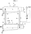
- FIG. 1 is a schematic top view showing a continuous fluorination apparatus used to produce 1,1,1,2,3-pentafluoropropane according to one example embodiment of the present invention.
- the catalytic reaction process is to bring a CoF 3 -containing cobalt fluoride supplied in a solid phase into contact with 3,3,3-trifluoropropene (HFO-1243zf) supplied in a gas phase in a reactor 10 to produce 1,1,1,2,3-pentafluoropropane (HFC-245eb).
- the reactor 10 may be formed in a tubular structure.
- the CoF 3 -containing cobalt fluoride and the 3,3,3-trifluoropropene are supplied through a CoF 3 supply port 12 and a source gas supply port 14, respectively, and may flow in opposite directions in the reactor 10 and be brought into countercurrent contact with each other.
- a rotary shaft having a plurality of paddle-type blades attached thereto is provided in the reactor 10, and the CoF 3 -containing cobalt fluoride may be transferred in a predetermined direction (for example, a direction indicated by arrow a) by rotation of the rotary shaft.
- a transfer rate of the CoF 3 -containing cobalt fluoride may be properly set by adjusting at least one of a rotation speed of the rotary shaft and an angle of the paddle-type blades.
- the paddle-type blades serve to transfer the CoF 3 -containing cobalt fluoride while rotating the CoF 3 -containing cobalt fluoride. Therefore, the paddle-type blades may be effectively used to stir a solid cobalt fluoride so as to facilitate the contact and heat transfer between the source gas and the solid cobalt fluoride.
- the CoF 3 in the CoF 3 -containing cobalt fluoride and the 3,3,3-trifluoropropene are subjected to the catalytic reaction represented by Scheme 7 to produce CoF 2 and 1,1,1,2,3-pentafluoropropane.
- a molar ratio between the CoF 3 and the 3,3,3-trifluoropropene used in the catalytic reaction may be in a range of 2:1 to 20:1.
- the CoF 3 may be presented at an excessive molar amount exceeding a stoichiometric amount required for the catalytic reaction, based on the molar amount of the 3,3,3-trifluoropropene (i.e., the number of moles of the CoF 3 exceeding 2 moles based on 1 mole of the 3,3,3-trifluoropropene).
- the CoF 3 -containing cobalt fluoride used in the catalytic reaction may be composed only of CoF 3 , but preferably may further include CoF 2 so that a molar ratio between the CoF 3 and the CoF 2 can fall within a range of 9:1 to 2:8.
- HFC-236ea (CF 3 CHFCHF 2 ) HFC-236cb (CF 3 CF 2 CH 2 F), HFC-227ea (CF 3 CHFCF 3 ), HFC-227ca (CF 3 CF 2 CHF 2 ) and FC-218 (CF 3 CF 2 CF 3 ) may be produced as the by-products, in addition to the desired product gas, 1,1,1,2,3-pentafluoropropane (HFC-245eb).
- the HFC-245eb is a compound produced by incorporating a fluorine atom into a double bond, and the others are compounds produced by substituting hydrogen with a fluorine atom. Since the conditions used to incorporate a fluorine atom into a double bond is milder than the conditions used to substitute hydrogen with a fluorine atom, a yield of the HFC-245eb may be maximized by properly adjusting a ratio between CoF 3 and CoF 2 in the catalyst.
- the CoF 3 -containing cobalt fluoride used in the catalytic reaction further include CoF 2
- the CoF 2 may serve as a diluent with respect to a CoF 3 catalyst. Therefore, an excessive catalytic reaction of a reactive gas may be suppressed to reduce production of the by-products rather than the HFC-245eb.
- the production of the by-products may be minimized by allowing the CoF 2 to be included at such an amount that the number of moles of the CoF2 is greater than the number of moles of the CoF 3 .
- the CoF 3 -containing cobalt fluoride used for the catalytic reaction may be diluted with a separate diluent.
- Various kinds of metal fluorides may be used as the diluents.
- CaF 2 having similar fluidity to the cobalt fluoride may be used herein.
- a level of dilution may be set to 80% of the entire weight, and may be properly adjusted according to diluents used and reaction conditions.
- an electric heater is attached to an outer wall of the reactor 10 to supply heat required for the catalytic reaction to the reactor 10.
- a proper reaction temperature in the reactor 10 is in a range of 150 to 300 °C, and the reaction temperature may be constantly maintained by providing cold air into a blower through a jacket installed outside the reactor 10.
- the source gas (HFO-1243zf) is supplied to the reactor 10 at a pressure of 0.05 to 0.1 MPa (0.5 to 1 kgcm 2 G), preferably 0.02 to 0.04 MPa (0.2 to 0.4 kgcm 2 G).
- the 1,1,1,2,3-pentafluoropropane produced in the reactor 10 is transferred in a direction opposite to a transfer direction of the CoF 3 -containing cobalt fluoride, and discharged through a product gas discharge port 32 of the reactor 10.
- a cobalt fluoride catalyst having a diameter of 2 mm or less in a fine powdery shape may be entrained with the product gas, and then discharged.
- the discharged cobalt fluoride catalyst may be collected and recovered while passing through an electrostatic precipitator 30 coupled to the product gas discharge port 32 of the reactor 10.
- the CoF 2 -containing cobalt fluoride produced as a result of the catalytic reaction is discharged through a CoF 2 discharge port 16 of the reactor 10, and transferred to the regenerator 20 through the first transfer unit 40.
- the catalyst regeneration process is to bring a CoF 2 -containing cobalt fluoride supplied in a solid phase into contact with a fluorine gas supplied in a gas phase in the regenerator 20 to produce a CoF 3 -containing cobalt fluoride.
- the regenerator 20 may be, for example, formed in a tubular structure.
- the CoF 2 -containing cobalt fluoride and the fluorine gas may be supplied through the CoF 2 supply port 22 and the fluorine gas supply port 24, respectively, and may flow in opposite directions in the regenerator 20 and be brought into countercurrent contact with each other.
- a rotary shaft having a plurality of paddle-type blades attached thereto is provided in the regenerator 20, and the CoF 2 -containing cobalt fluoride may be transferred in a predetermined direction (for example, a direction indicated by arrow b) by rotation of the rotary shaft.
- a transfer rate of the CoF 2 -containing cobalt fluoride may be properly set by adjusting at least one of a rotation speed of the rotary shaft and an angle of the paddle-type blades.
- the paddle-type blades serve to transfer the CoF 2 -containing cobalt fluoride while rotating the CoF 2 -containing cobalt fluoride. Therefore, the paddle-type blades may be effectively used to stir a solid cobalt fluoride so as to facilitate the contact and heat transfer between the fluorine gas and the solid cobalt fluoride.
- the CoF 2 in the CoF 2 -containing cobalt fluoride and the fluorine gas are subjected to the catalyst regeneration reaction represented by Scheme 7 to produce CoF 3 .
- a molar ratio between the CoF 2 and the fluorine gas may be in a range of 2:1 to 20:1.
- the CoF 2 may be present at an excessive molar amount exceeding a stoichiometric amount required for the catalyst regeneration reaction, based on the molar amount of the fluorine gas (i.e., the number of moles of the CoF 2 exceeding 2 moles based on 1 mole of the fluorine gas).
- the fluorine gas is temporally supplied at a more excessive amount than a predetermined amount of the fluorine gas due to abnormal driving of the regenerator 20, an extra CoF 2 may react with the fluorine gas, thereby preventing production of a non-reacted fluorine gas.
- the fluorine gas does not sufficiently react with CoF 2 under normal driving of the regenerator 20
- the non-reacted fluorine gas may be produced.
- the fluorine gas since an extra CoF 2 reacts with the non-reacted fluorine gas, the fluorine gas may be prevented from moving to the reactor 10.
- the CoF 2 -containing cobalt fluoride used for the catalyst regeneration reaction may be composed only of CoF 2 , but preferably may further include CoF 3 so that a molar ratio between the CoF 2 and the CoF 3 can fall within a range of 9:1 to 2:8.
- the fluorine gas is supplied to the regenerator 20 at an insufficient amount compared to the predetermined amount of the fluorine gas, an extra CoF 3 may take part in the catalytic reaction in the reactor 10, thereby stably maintaining a conversion rate of the catalytic reaction (yield of a product gas).
- An electric heater is attached to an outer wall of the regenerator 20 to supply heat required for the catalyst regeneration reaction to the regenerator 20.
- a proper reaction temperature is in a range of 250 to 350 °C, and the reaction temperature may be constantly maintained by providing cold air into a blower through a jacket installed outside the regenerator 20.
- the fluorine gas is supplied to the regenerator 20 at a pressure of 0.05 to 0.1 MPa (0.5 to 1 kgcm 2 G, preferably 0.02 to 0.04 MPa (0.2 to 0.4 kgcm 2 G).
- the CoF 3 -containing cobalt fluoride regenerated in the catalyst regeneration reaction is discharged through the CoF 3 discharge port 26 of the regenerator 20, and then transferred to the reactor 10 through the second transfer unit 50.
- the CoF 2 -containing cobalt fluoride discharged from the reactor 10 after the catalytic reaction process is transferred to the regenerator 20 through the first transfer unit 40, and the transferred CoF 2 -containing cobalt fluoride is regenerated into a CoF 3 -containing cobalt fluoride by a catalyst regeneration process.
- the CoF 3 -containing cobalt fluoride regenerated in the regenerator 20 is transferred to the reactor 10 through the second transfer unit 50, and the transferred CoF 3 -containing cobalt fluoride is subjected to a catalytic reaction process to produce a CoF 2 -containing cobalt fluoride and a product gas (HFC-245eb).
- first and second transfer units 40 and 50 serve to circulate the cobalt fluorides, which are used for the catalytic reaction process and the catalyst regeneration process, between the reactor 10 and the regenerator 20.
- the first and second transfer units 40 and 50 may be screw conveyors, each of which has screws formed therein.
- the transfer of the CoF 2 -containing cobalt fluoride from the reactor 10 to the regenerator 20 may be carried out using the first screw conveyor 40 coupled to the reactor 10 and the regenerator 20 so that an upward slope is formed from the reactor 10 toward the regenerator 20.
- the transfer of the CoF 3 -containing cobalt fluoride from the regenerator 20 to the reactor 10 may be carried out using the second screw conveyor 50 coupled to the regenerator 20 and the reactor 10 so that an upward slope is formed from the regenerator 20 toward the reactor 10.
- FIG. 2 is a schematic side view showing the continuous fluorination apparatus according to one example embodiment of the present invention.
- the first screw conveyor 40 is coupled in an upward slope so that the CoF 2 can be transferred from the CoF 2 discharge port 16 disposed at a lower portion of the reactor 10 to the CoF 2 supply port 22 disposed at an upper portion of the regenerator 20.
- the second screw conveyor 50 is coupled in an upward slope so that the CoF 3 can be transferred from the CoF 3 discharge port 26 disposed at a lower portion of the regenerator 20 to the CoF 3 supply port 12 disposed at an upper portion of the reactor 10.
- Inclination angles of the first and second screw conveyors 40 and 50 may be in a range of 20° to 90°.
- the first and second screw conveyors 40 and 50 may be installed in an upper slope to transfer the cobalt fluoride, and thus the first and second screw conveyors 40 and 50 may transfer the cobalt fluoride while being filled with no empty space therein. Therefore, it is possible to effectively prevent the reactive gas from moving to the regenerator 20 through the first screw conveyor 40, or prevent the fluorine gas from moving to the reactor 10 through the second screw conveyor 50.
- the first screw conveyor 40 may serve to increase a temperature of the CoF 2 -containing cobalt fluoride transferred using an external electric heater
- the second screw conveyor 50 may serve to decrease a temperature of the CoF 3 -containing cobalt fluoride transferred by allowing cooling water to flow in an external jacket.
- compositions of the cobalt fluoride flowing between the reactor 10 and the regenerator 20 may be realized in a state in which CoF 2 and CoF 3 co-exist at a predetermined ratio.
- Table 1 lists one example embodiment of a cobalt fluoride whose compositions are run at a predetermined composition ratio in the reactor 10 and the regenerator 20.
- Table 1 Fluorine gas Source gas Compositions of cobalt fluoride supplied to regenerator (after catalytic reaction and before beginning of catalyst regeneration) Compositions of cobalt fluoride supplied to reactor (after catalyst regeneration and before beginning of catalytic reaction) 10 mole/hr 10 mole/hr CoF 3 10 to 30 mole/hr CoF 3 30 to 50 mole/hr CoF 2 90 to 70 mole/hr CoF 2 70 to 50 mole/hr 10 mole/hr 10 mole/hr CoF 3 10 to 30 mole/hr CoF 3 30 to 50 mole/hr CoF 2 190 to 170 mole/hr CoF 2 170 to 150 mole/hr
- the optimum conversion rate from HFO-1243zf to HFC-245eb and the selectivity may be readily adjusted by adjusting a ratio of the source gas and fluorine gas to the cobalt fluoride or a ratio between CoF 3 and CoF 2 at a constant reaction temperature.
- a reaction system was prepared, as shown in FIG. 1 .
- Each of a reactor and a regenerator was provided with a shaft (with a diameter of 10 cm) rotating at a constant rate in a stainless steel tube (with a diameter of 30 cm and a length of 250 cm), and a cobalt fluoride was moved forward at a constant rate by adjusting an angle of paddle-type blades attached to the shaft.
- the paddle-type blades attached to the shaft were welded in a state in which a tube having a diameter of 3.8 cm was fit through the shaft, and paddles were alternately installed with respect to each other.
- the blades attached to the paddles had a rectangular shape so that a powdery solid cobalt fluoride could be readily spread. Also, the blades might move with being fit into an end of a paddle tube, and be fixed with bolts to adjust a desired angle of the blades.
- the cobalt fluoride was filled respectively in the reactor and the regenerator at a charge amount of 24 to 48 kg so that the a charge amount of the cobalt fluoride reached 20 to 40% (% by bulk volume) of the volume of each of the reactor and the regenerator.
- Rotation speeds of shafts of the reactor and the regenerator were fixed at 9.4 RPM, and the angle of the blades attached to the paddles was adjusted and set so that the flow velocity of the cobalt fluoride reached 48 to 96 kg/hr, depending on an amount of the cobalt fluoride.
- a bow-shaped electric heater was installed outside the reactor and the regenerator to supply heat required for the catalytic reaction and catalyst regeneration reaction, and the heat generated during a catalytic reaction process and a catalyst regeneration process was cooled by supplying cold air from a lower portion to an upper portion through a jacket installed outside the electric heater so as to maintain a constant temperature.
- the first screw conveyor was installed so that a tube having a diameter of 10 cm was formed aslant at an angle of approximately 30° from a lower portion of a rear stage of the reactor (a portion of the rear stage through which the cobalt fluoride undergoing the catalytic reaction is transferred, the same as above) to an upper portion of a front stage of the regenerator (a portion of the front stage through which the cobalt fluoride starts to flow for the catalyst regeneration reaction, the same as above).
- the second screw conveyor was installed so that a tube having a diameter of 10 cm was formed aslant at an angle of approximately 30° from a lower portion of a rear stage of the regenerator (a portion of the rear stage through which the cobalt fluoride undergoing the catalyst regeneration reaction is transferred, the same as above) to an upper portion of a front stage of the reactor (a portion of the front stage through which the cobalt fluoride starts to flow for the catalytic reaction, the same as above).
- the first and second screw conveyors transferred the catalyst in an upward direction due to the presence of internal screws, and a maximum transfer rate was set to 120 kg/hr.
- a rotation speed of the screws was 50 rpm in maximum, and an inverter was used to adjust alternating current frequencies, thereby adjusting a transfer rate.
- the first screw conveyor used an external electric heater to increase a temperature while transferring the cobalt fluoride in the reactor to the regenerator, and the second screw conveyor allowed cooling water to flow through an external jacket to decrease a temperature while transferring the cobalt fluoride in the regenerator to the reactor.
- the product (HFC-245eb) produced in the reactor was discharged through the front-stage discharge port of the reactor, and the entrained cobalt fluoride catalyst was collected using an electrostatic precipitator.
- the cobalt fluoride attached to an electrostatic precipitator was detached by periodically applying vibrations to the electrostatic precipitator, and then transferred to the first screw conveyor.
- the catalyst-free product was compressed and stored to calculate a yield and compositions of the product.
- the CoF 2 was completely discharged. Thereafter, the first screw conveyor was assembled, and a catalyst was added through an inspection hole of the rear stage of the regenerator while rotating the screws of the conveyors and the paddle shafts of the reactor and the regenerator. Then, moisture in the catalyst was completely removed while allowing nitrogen to flow at a flow rate of 2 L/min to 15 L/min through a source gas input of the reactor (a point of approximately 2/3 apart from the front stage of the reactor) as temperatures of heaters of the reactor and the regenerator were gradually increased to 350 °C. In this case, the electrostatic precipitator was run.
- a total of 48 kg of CoF 2 was added into the reactor and the regenerator, the angle of the blades attached to the paddles was adjusted, and the number of rotations of the screws of each conveyor was adjusted so that a transfer rate of CoF 2 reached 48 kg/hr. Thereafter, internal temperatures of the reactor and the regenerator were increased by allowing nitrogen to flow in the reactor and the regenerator (flow rate of 2 L/min to 15 L/min), thereby removing moisture in CoF 2 . When the moisture in CoF 2 was completely removed, the internal temperatures of the reactor and the regenerator were maintained respectively to a temperature of 250 °C while gradually decreasing a flow rate of nitrogen to 2 L/min.
- a fluorine gas was added to the regenerator at a rate of 0.94 kg/hr for 3 hours, and the addition of the fluorine gas was then suspended.
- a fluorination temperature of the regenerator was constantly maintained at 250 °C.
- An initial molar ratio between CoF 3 and CoF 2 was adjusted by changing an addition time (3 hours, 2 hours and 1 hour) of an initial fluorine gas without adding the source gas (1243zf) when CoF 2 was filled to 100%.
- Table 2 lists ratios of products at a cobalt fluoride flow rate of 48 kg/hr according to changes in reaction temperature of the reactor and composition ratio of initial CoF 3 /CoF 2 , as analyzed using GC.
- Table 2 Experimental Example Initial molar ratio CoF 3 /CoF 2 /1243zf molar ratio in reactor before reaction Reactor (°C) 1243 zf 245eb 236ea 236cb 227ea 227ca 218 CF 4 1 3/7 5/5/1 250 0.2 70.5 17.2 5.5 2.1 3.2 0.6 0.2 2 200 12.8 69.7 11.1 1.3 1.1 1.3 1.3 0.3 0.1 3 150 39.5 47.8 6.7 2.2 0.7 1.4 0.2 - 4 2/8 4/6/1 250 2.8 77.2 13.2 3.3 1.4 0.9 0.5 0.1 5 200 18.4 70.0 7.7 1.6 0.7 0.8 0.2 0.1 6 150 40.8 46.7 6.5 2.2 0.7 0.9 0.2 - 7 1/9 3/7/1 250
- HFC-245eb 1,1,1,2,3-pentafluoropropane
- Experimental Examples 10 to 13 were carried out in the same manner as in Experimental Examples 1 to 9, except that a total of 96 kg of CoF 2 was added to each of the reactor and the regenerator.
- Table 3 lists ratios of products at a cobalt fluoride flow rate of 96 kg/hr according to changes in reaction temperature of the reactor and composition ratio of initial CoF 3 /CoF 2 , as analyzed using GC.
- Table 3 Experimental Example Initial CoF 3 /CoF 2 molar ratio CoF 3 /CoF 2 /1243zf molar ratio in reactor before reaction Reactor (°C) 1243 zf 245eb 236ea 236cb 227ea 227ca 218 CF 4 10 3/17 5/15/1 300 - 85.3 6.5 5.5 1.3 1.3 - 0.2 12 250 2.5 91.3 2.4 2.1 - - - - 13 200 15.2 84.2 0.2 0.2 - - - - - - -
- 1,1,1,2,3-pentafluoropropane can be continuously produced with high yield from 3,3,3-trifluoropropene using a cobalt fluoride (CoF 2 /CoF 3 ) as a fluid catalyst.
- a cobalt fluoride CoF 2 /CoF 3
- the reaction stability can be improved and the optimum conversion rate and selectivity can be readily adjusted by adjusting a ratio between 3,3,3-trifluoropropene or fluorine gas and a cobalt fluoride and a ratio between CoF 2 and CoF 3 in the cobalt fluoride.
Landscapes
- Chemical & Material Sciences (AREA)
- Organic Chemistry (AREA)
- Chemical Kinetics & Catalysis (AREA)
- Engineering & Computer Science (AREA)
- Materials Engineering (AREA)
- Organic Low-Molecular-Weight Compounds And Preparation Thereof (AREA)
- Catalysts (AREA)
Description
- Example embodiments of the present invention relate in general to the field of production of 1,1,1,2,3-pentafluoropropane, and, more specifically, to a method and apparatus for continuously producing 1,1,1,2,3-pentafluoropropane with high yield.
- 1,1,1,2,3-pentafluoropropane (CF3CHFCH2F, HFC-245eb) is an intermediate useful in manufacture of 2,3,3,3-tetrafluoropropene (CF3CF=CH2, HFO-1234yf), which is effectively used as an alternative refrigerant of chlorofluorocarbon refrigerants, as represented by the following Scheme 1.

- A method which includes sequentially performing hydrogenation, dehydrofluorination and hydrogenation of hexafluoropropene (HFP, CF3CF=CF2), as represented by the following Scheme 2, is known in the art as the method of producing HFC-245eb.
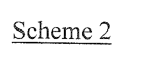

- However, the method of producing HFO-1234yf as represented by Schemes 1 and 2 has problems in that a raw material, HFP, is relatively expensive, and is a complicated process which is composed of four operations including two hydrogenations and two dehydrofluorinations, which leads to relatively low industrial competitiveness.
- A method of producing HFO-1234yf without producing HFC-245eb as an intermediate is a process using 1,1,1,3-tetrachloropropane (CCl3CH2CH2Cl, HCC-250fb) as a raw material. HCC-250fb is produced through a reaction between carbon tetrachloride (CCl4) and ethylene (CH2=CH2) as represented by the following Scheme 3. Here, the carbon tetrachloride and the ethylene are relatively inexpensive and can be readily supplied on a commercial scale.

- To produce HFO-1234yf using the HCC-250fb as a starting material, it is necessary to substitute one hydrogen atom bound to a central carbon atom with a halogen atom (F, Cl, Br, or I). In this regard, two methods are known in the related art (see e.g.
US 6,162,955 ). - In this method, first, dehydrochlorination, chlorination and dehydrochlorination of HCC-250fb are sequentially carried out to produce 1,1,2,3-tetrachloropropene (CCl2=CClCH2Cl, HCO-1230xa) in which a hydrogen atom of the carbon in the center of the molecule is substituted with a chlorine atom.
- Next, the HCO-1230xa is subjected to two operations of hydrofluorination and dehydrochlorination to produce HFO-1234yf.
- However, a photo-reaction is included in chlorination during production of the HCO-1230xa, and two by-products, HCO-1230xf (CCl3CCl=CH2) and HCO-1230zd (CCl3CH=CHCl), are also produced in addition to the HCO-1230xa as products of final dehydrochlorination. Therefore, an additional process for converting the by-products into HCO-1230xa is required (see
US Publication No. 2012/0022303 ). Accordingly, the HCO-1230xa is relatively expensive and is not readily distributed on a commercial scale since it is produced with complicated operations as described above. - In this method, first, fluorination and dehydrochlorination of HCC-250fb are carried out to produce 3,3,3-trifluoropropene (CF3CH=CH2, HFO-1243zf), as represented by the following Scheme 4.

- Next, the produced HFO-1243zf i) is subjected to chlorination, followed by hydrofluorination to produce HFO-1234yf, as represented by the following Scheme 5, or ii) is simultaneously subjected to chlorination/hydrofluorination (chlorofluorination) to produce HFO-1234yf, as represented by the following Scheme 6.


- However, when the reaction is carried out as represented by Scheme 5 or 6, significant amounts of side reaction products such as 1233zd and 1234ze are produced. Therefore, a separate process for handling the 1233zd or 1234ze is required.
- In summary, when HFO-1234yf is produced as a next-generation alternative refrigerant, a method of producing 1,1,1,2,3-pentafluoropropane (CF3CHFCH2F, HFC-245eb) as an intermediate has an advantage in that it can be used to produce HFO-1234yf simply and effectively, compared to the other methods. However, when HFP is used as a starting material to produce the HFC-245eb, this is not commercially viable due to its economic inefficiency. On the other hand, when a relatively inexpensive raw material, HCC-250fb, is used without undergoing a process for producing HFC-245eb, a multi-stage process is required. Also, since large amounts of by-products are produced by side reactions, a complicated process for handling the by-products is also required.
- Meanwhile, there is a direct fluorination method of directly producing HFC-245eb through a direct reaction of HFO-1243zf with fluorine gas. In this case, however, carbon-carbon cleavage may take place due to high reactivity of the fluorine gas, and many by-products such as HFC-236ea (CF3CHFCHF2), HFC-236cb (CF3CF2CH2F), HFC-227ea (CF3CHFCF3), HFC-227ca (CF3CF2CHF2) and FC-218 (CF3CF2CF3) may be produced. To carry out a fluorination reaction under milder conditions, a method of diluting fluorine gas with an excessive amount of nitrogen gas is known in the art. In this case, however, there are problems related to a localized fluorination reaction and a separation of low-boiling-point products and nitrogen. In particular, it is difficult to take a commercial approach to this method due to difficulty in handling non-reacted fluorine gases.
-
US 2007/112230 A1 discloses a method for producing fluorinated organic compounds, including hydrofluoropropenes, which preferably comprises converting at least one compound of formula (I): CF3CHXCH2X to at least one compound of formula (II): CF3CZCHZ, where X is independently Cl, Br, I or F, and Z independently is H or F. - Douglas A Rausch; Davis Ralph A; Osborne D Wendell, "The Addition of Fluorine to Halogenated Olefins by Means of Metal Fluorides", The Journal of Organic Chemistry, (1963), vol:28, no.2, pages 494 - 497 describes the selective addition of fluorine to the double bond of olefins by means of vapor phase reaction with cobalt trifluoride to provide for stable halogenated olefins.
-
GB 789 441 A -
US 2,759,026 A describes a method for carrying out the fluorination of organic compounds, more specifically a method for fluorinating hydrocarbons or hydrocarbon compounds such as halogen substituted hydrocarbons by reactions including addition to fluorine to double or triple bonds, hydrogen substitution and halogen exchange. - Accordingly, example embodiments of the present invention are provided to substantially obviate one or more problems due to limitations and disadvantages of the
- Example embodiments of the present invention provide a method of producing HFC-245eb, which is an intermediate of HFO-1234yf, with high yield using 3,3,3-trifluoropropene (CF3CH=CH2, HFO-1243zf), which is produced from an inexpensive raw material, HCC-250fb, through fluorination and dehydrochlorination, as a starting material.
- Example embodiments of the present invention also provide a method of continuously producing HFC-245eb from HFO-1243zf with high yield using an indirect fluorination method (i.e., mild fluorination) in which a cobalt fluoride (CoF2/CoF3) is used as a fluid catalyst.
- A method of continuously producing 1,1,1,2,3-pentafluoropropane is provided. The method includes (a) bringing a CoF3-containing cobalt fluoride into contact with 3,3,3-trifluoropropene in a reactor to produce a CoF2-containing cobalt fluoride and 1,1,1,2,3-pentafluoropropane, (b) transferring the CoF2-containing cobalt fluoride in the reactor to a regenerator and bringing the transferred CoF2-containing cobalt fluoride into contact with fluorine gas to regenerate a CoF3-containing cobalt fluoride, and (c) transferring the CoF3-containing cobalt fluoride in the regenerator to the reactor and employing the transferred CoF3-containing cobalt fluoride in Operation (a).
- The contact of the CoF3-containing cobalt fluoride with the 3,3,3-trifluoropropene in Operation (a), and the contact of the CoF2-containing cobalt fluoride with the fluorine gas in Operation (b) may be carried out by countercurrent contact.
- The reactor and the regenerator may comprise a rotary shaft having paddle-type blades attached thereto, and the cobalt fluorides in the reactor and the regenerator may be transferred by rotation of the rotary shaft. In addition, a transfer rate of the cobalt fluorides in the reactor and the regenerator may be adjusted by adjusting an angle of the paddle-type blades attached to the rotary shaft.
- In Operation (a), a molar ratio between the CoF3 in the CoF3-containing cobalt fluoride and the 3,3,3-trifluoropropene may be in a range of 2:1 to 20:1.
- Also in Operation (a), the CoF3-containing cobalt fluoride may further include CoF2 so that a molar ratio between CoF3 and CoF2 can fall within a range of 9:1 to 2:8. In this case, the CoF2 may be included at such an amount that the number of moles of the CoF2 is greater than the number of moles of the CoF3 within the molar ratio between the CoF3 and the CoF2.
- In Operation (b), a molar ratio between the CoF2 in the CoF2-containing cobalt fluoride and the fluorine gas may be in a range of 2:1 to 20:1.
- Also in Operation (b), the CoF2-containing cobalt fluoride may further include CoF3 so that a molar ratio between CoF2 and CoF3 can fall within a range of 9:1 to 2:8.
- Meanwhile, in Operation (a), the CoF3-containing cobalt fluoride may be used in a state of being diluted with a metal fluoride.
- The transfer of the CoF2-containing cobalt fluoride from the reactor to the regenerator may be carried out using a first screw conveyor coupled to the reactor and the regenerator so that an upward slope is formed from the reactor toward the regenerator. Also, the transfer of the CoF3-containing cobalt fluoride from the regenerator to the reactor may be carried out using a second screw conveyor coupled to the regenerator and the reactor so that an upward slope is formed from the regenerator to the reactor.
- The apparatus for continuously producing 1,1,1,2,3-pentafluoropropane includes a reactor configured to bring a CoF3-containing cobalt fluoride into countercurrent contact with 3,3,3-trifluoropropene to produce a CoF2-containing cobalt fluoride and 1,1,1,2,3-pentafluoropropane, a first screw conveyor configured to draw the CoF2-containing cobalt fluoride from the reactor, a regenerator configured to receive the CoF2-containing cobalt fluoride from the first screw conveyor and bring the received CoF2-containing cobalt fluoride into countercurrent contact with fluorine gas to regenerate a CoF3-containing cobalt fluoride, and a second screw conveyor configured to draw the CoF3-containing cobalt fluoride from the regenerator and transfer the CoF3-containing cobalt fluoride to the reactor.
- The reactor and the regenerator may comprise a rotary shaft having paddle-type blades attached thereto, and the cobalt fluorides in the reactor and the regenerator may be transferred by rotation of the rotary shaft. In addition, a transfer rate of the cobalt fluorides in the reactor and the regenerator may be adjusted by adjusting an angle of the paddle-type blades attached to the rotary shaft.
- The first screw conveyor may be coupled to the reactor and the regenerator so that an upward slope is formed from the reactor to the regenerator. Also, the second screw conveyor may be coupled to the regenerator and the reactor so that an upward slope is formed from the regenerator to the reactor.
- Also, the apparatus for continuously producing 1,1,1,2,3-pentafluoropropane may further include an electrostatic precipitator configured to receive 1,1,1,2,3-pentafluoropropane produced in the reactor and recover the CoF3-containing cobalt fluoride that may be entrained with the received 1,1,1,2,3-pentafluoropropane.
- Example embodiments of the present invention will become more apparent by describing in detail example embodiments of the present invention with reference to the accompanying drawings, in which:
-
FIG. 1 is a schematic top view showing a continuous fluorination apparatus used to produce 1,1,1,2,3-pentafluoropropane according to one example embodiment of the present invention; and -
FIG. 2 is a schematic side view showing the continuous fluorination apparatus according to one example embodiment of the present invention. - Example embodiments of the present invention are disclosed herein.
- It will be understood that, although the terms first, second, etc. may be used herein to describe various elements, these elements should not be limited by these terms. These terms are only used to distinguish one element from another. For example, a first element could be termed a second element, and, similarly, a second element could be termed a first element, without departing from the scope of the present invention. As used herein, the term "and/or" includes any and all combinations of one or more of the associated listed items.
- It will be understood that when an element is referred to as being "connected" or "coupled" to another element, it can be directly connected or coupled to the other element or intervening elements may be present. In contrast, when an element is referred to as being "directly connected" or "directly coupled" to another element, there are no intervening elements present. Other words used to describe the relationship between elements should be interpreted in a like fashion (i.e., "between" versus "directly between," "adjacent" versus "directly adjacent," etc.).
- In the description of the present invention, the term "cobalt fluoride" means a substance including at least one of cobalt(II) fluoride (CoF2) and cobalt(III) fluoride (CoF3).
- Also, it should be understood that the term "CoF2-containing cobalt fluoride" means a cobalt fluoride including at least CoF2 as an effective component, and the term "CoF3-containing cobalt fluoride" means a cobalt fluoride including at least CoF3 as an effective component. Therefore, this is not intended to exclude the CoF2-containing cobalt fluoride from further including CoF3, or the CoF3-containing cobalt fluoride from further including CoF2.
- Also, the term "cobalt fluoride catalyst" or "catalyst" is used to have the same meaning as the cobalt fluoride including at least CoF3.
- A source gas or reactive gas is used with the same meaning as 3,3,3-trifluoropropene (HFO-1243zf), and a product gas is used with the same meaning as 1,1,1,2,3-pentafluoropropane (HFC-245eb).
- The present invention relates to a method of continuously producing 1,1,1,2,3-pentafluoropropane through fluorination of 3,3,3-trifluoropropene using a cobalt fluoride as a fluid catalyst.
- More particularly, the method includes (a) bringing a CoF3-containing cobalt fluoride into contact with 3,3,3-trifluoropropene in a reactor to produce a CoF2-containing cobalt fluoride and 1,1,1,2,3-pentafluoropropane, (b) transferring the CoF2-containing cobalt fluoride in the reactor to a regenerator and bringing the transferred CoF2-containing cobalt fluoride into contact with fluorine gas to regenerate a CoF3-containing cobalt fluoride, and (c) transferring the CoF3-containing cobalt fluoride in the regenerator to the reactor and employing the transferred CoF3-containing cobalt fluoride in Operation (a).
- Operations (a) to (c) may be referred to as a catalytic reaction process (a), a catalyst regeneration process (b), and a catalyst reuse process (c), respectively.
- The processes is continuously carried out, and the catalytic reaction process (a) and the catalyst regeneration process (b) may be represented by the following Scheme 7.
- Catalytic reaction process : 2CoF3 + CF3CH=CH2 →2CoF2 + CF3CHFCH2F
- Catalyst regeneration process : 2CoF2 + F2 →2CoF3
-
FIG. 1 is a schematic top view showing a continuous fluorination apparatus used to produce 1,1,1,2,3-pentafluoropropane according to one example embodiment of the present invention. - Hereinafter, the processes will be described in detail with reference to
FIG. 1 . - The catalytic reaction process is to bring a CoF3-containing cobalt fluoride supplied in a solid phase into contact with 3,3,3-trifluoropropene (HFO-1243zf) supplied in a gas phase in a
reactor 10 to produce 1,1,1,2,3-pentafluoropropane (HFC-245eb). For example, thereactor 10 may be formed in a tubular structure. - The CoF3-containing cobalt fluoride and the 3,3,3-trifluoropropene are supplied through a CoF3 supply port 12 and a source
gas supply port 14, respectively, and may flow in opposite directions in thereactor 10 and be brought into countercurrent contact with each other. - According to one example embodiment, a rotary shaft having a plurality of paddle-type blades attached thereto is provided in the
reactor 10, and the CoF3-containing cobalt fluoride may be transferred in a predetermined direction (for example, a direction indicated by arrow a) by rotation of the rotary shaft. In this case, a transfer rate of the CoF3-containing cobalt fluoride may be properly set by adjusting at least one of a rotation speed of the rotary shaft and an angle of the paddle-type blades. The paddle-type blades serve to transfer the CoF3-containing cobalt fluoride while rotating the CoF3-containing cobalt fluoride. Therefore, the paddle-type blades may be effectively used to stir a solid cobalt fluoride so as to facilitate the contact and heat transfer between the source gas and the solid cobalt fluoride. - In the
reactor 10, the CoF3 in the CoF3-containing cobalt fluoride and the 3,3,3-trifluoropropene are subjected to the catalytic reaction represented by Scheme 7 to produce CoF2 and 1,1,1,2,3-pentafluoropropane. - In this case, a molar ratio between the CoF3 and the 3,3,3-trifluoropropene used in the catalytic reaction may be in a range of 2:1 to 20:1. In particular, the CoF3 may be presented at an excessive molar amount exceeding a stoichiometric amount required for the catalytic reaction, based on the molar amount of the 3,3,3-trifluoropropene (i.e., the number of moles of the CoF3 exceeding 2 moles based on 1 mole of the 3,3,3-trifluoropropene). In this case, when the CoF3 is not regenerated to a desired extent due to insufficient supply of the fluorine gas in the
regenerator 20 as will be described later, an extra CoF3 may take part in the catalytic reaction in thereactor 10, thereby stably maintaining a conversion rate of the catalytic reaction (yield of a product gas). - Meanwhile, the CoF3-containing cobalt fluoride used in the catalytic reaction may be composed only of CoF3, but preferably may further include CoF2 so that a molar ratio between the CoF3 and the CoF2 can fall within a range of 9:1 to 2:8. When the fluorination of 3,3,3-trifluoropropene (HFO-1243zf) is carried out, many fluorides such as HFC-236ea (CF3CHFCHF2) HFC-236cb (CF3CF2CH2F), HFC-227ea (CF3CHFCF3), HFC-227ca (CF3CF2CHF2) and FC-218 (CF3CF2CF3) may be produced as the by-products, in addition to the desired product gas, 1,1,1,2,3-pentafluoropropane (HFC-245eb). Among these, only the HFC-245eb is a compound produced by incorporating a fluorine atom into a double bond, and the others are compounds produced by substituting hydrogen with a fluorine atom. Since the conditions used to incorporate a fluorine atom into a double bond is milder than the conditions used to substitute hydrogen with a fluorine atom, a yield of the HFC-245eb may be maximized by properly adjusting a ratio between CoF3 and CoF2 in the catalyst.
- That is, when the CoF3-containing cobalt fluoride used in the catalytic reaction further include CoF2, the CoF2 may serve as a diluent with respect to a CoF3 catalyst. Therefore, an excessive catalytic reaction of a reactive gas may be suppressed to reduce production of the by-products rather than the HFC-245eb. In particular, when the CoF3-containing cobalt fluoride further including CoF2 is supplied, the production of the by-products may be minimized by allowing the CoF2 to be included at such an amount that the number of moles of the CoF2 is greater than the number of moles of the CoF3.
- Also, in order to obtain the effect according to dilution of the CoF3 as described above, the CoF3-containing cobalt fluoride used for the catalytic reaction may be diluted with a separate diluent. Various kinds of metal fluorides may be used as the diluents. By way of example, CaF2 having similar fluidity to the cobalt fluoride may be used herein. A level of dilution may be set to 80% of the entire weight, and may be properly adjusted according to diluents used and reaction conditions.
- Meanwhile, an electric heater is attached to an outer wall of the
reactor 10 to supply heat required for the catalytic reaction to thereactor 10. A proper reaction temperature in thereactor 10 is in a range of 150 to 300 °C, and the reaction temperature may be constantly maintained by providing cold air into a blower through a jacket installed outside thereactor 10. - The source gas (HFO-1243zf) is supplied to the
reactor 10 at a pressure of 0.05 to 0.1 MPa (0.5 to 1 kgcm2G), preferably 0.02 to 0.04 MPa (0.2 to 0.4 kgcm2G). - The 1,1,1,2,3-pentafluoropropane produced in the
reactor 10 is transferred in a direction opposite to a transfer direction of the CoF3-containing cobalt fluoride, and discharged through a productgas discharge port 32 of thereactor 10. In this case, a cobalt fluoride catalyst having a diameter of 2 mm or less in a fine powdery shape may be entrained with the product gas, and then discharged. The discharged cobalt fluoride catalyst may be collected and recovered while passing through anelectrostatic precipitator 30 coupled to the productgas discharge port 32 of thereactor 10. - Also, the CoF2-containing cobalt fluoride produced as a result of the catalytic reaction is discharged through a CoF2 discharge port 16 of the
reactor 10, and transferred to theregenerator 20 through thefirst transfer unit 40. - The catalyst regeneration process is to bring a CoF2-containing cobalt fluoride supplied in a solid phase into contact with a fluorine gas supplied in a gas phase in the
regenerator 20 to produce a CoF3-containing cobalt fluoride. Theregenerator 20 may be, for example, formed in a tubular structure. - The CoF2-containing cobalt fluoride and the fluorine gas may be supplied through the CoF2 supply port 22 and the fluorine
gas supply port 24, respectively, and may flow in opposite directions in theregenerator 20 and be brought into countercurrent contact with each other. - According to one example embodiment, a rotary shaft having a plurality of paddle-type blades attached thereto is provided in the
regenerator 20, and the CoF2-containing cobalt fluoride may be transferred in a predetermined direction (for example, a direction indicated by arrow b) by rotation of the rotary shaft. In this case, a transfer rate of the CoF2-containing cobalt fluoride may be properly set by adjusting at least one of a rotation speed of the rotary shaft and an angle of the paddle-type blades. - The paddle-type blades serve to transfer the CoF2-containing cobalt fluoride while rotating the CoF2-containing cobalt fluoride. Therefore, the paddle-type blades may be effectively used to stir a solid cobalt fluoride so as to facilitate the contact and heat transfer between the fluorine gas and the solid cobalt fluoride.
- In the
regenerator 20, the CoF2 in the CoF2-containing cobalt fluoride and the fluorine gas are subjected to the catalyst regeneration reaction represented by Scheme 7 to produce CoF3. - In this case, a molar ratio between the CoF2 and the fluorine gas may be in a range of 2:1 to 20:1. In particular, the CoF2 may be present at an excessive molar amount exceeding a stoichiometric amount required for the catalyst regeneration reaction, based on the molar amount of the fluorine gas (i.e., the number of moles of the CoF2 exceeding 2 moles based on 1 mole of the fluorine gas). In this case, although the fluorine gas is temporally supplied at a more excessive amount than a predetermined amount of the fluorine gas due to abnormal driving of the
regenerator 20, an extra CoF2 may react with the fluorine gas, thereby preventing production of a non-reacted fluorine gas. Also, as the fluorine gas does not sufficiently react with CoF2 under normal driving of theregenerator 20, the non-reacted fluorine gas may be produced. In this case, since an extra CoF2 reacts with the non-reacted fluorine gas, the fluorine gas may be prevented from moving to thereactor 10. - Meanwhile, the CoF2-containing cobalt fluoride used for the catalyst regeneration reaction may be composed only of CoF2, but preferably may further include CoF3 so that a molar ratio between the CoF2 and the CoF3 can fall within a range of 9:1 to 2:8. In this case, although the fluorine gas is supplied to the
regenerator 20 at an insufficient amount compared to the predetermined amount of the fluorine gas, an extra CoF3 may take part in the catalytic reaction in thereactor 10, thereby stably maintaining a conversion rate of the catalytic reaction (yield of a product gas). - An electric heater is attached to an outer wall of the
regenerator 20 to supply heat required for the catalyst regeneration reaction to theregenerator 20. A proper reaction temperature is in a range of 250 to 350 °C, and the reaction temperature may be constantly maintained by providing cold air into a blower through a jacket installed outside theregenerator 20. - The fluorine gas is supplied to the
regenerator 20 at a pressure of 0.05 to 0.1 MPa (0.5 to 1 kgcm2G, preferably 0.02 to 0.04 MPa (0.2 to 0.4 kgcm2G). - Also, the CoF3-containing cobalt fluoride regenerated in the catalyst regeneration reaction is discharged through the CoF3 discharge port 26 of the
regenerator 20, and then transferred to thereactor 10 through thesecond transfer unit 50. - The CoF2-containing cobalt fluoride discharged from the
reactor 10 after the catalytic reaction process is transferred to theregenerator 20 through thefirst transfer unit 40, and the transferred CoF2-containing cobalt fluoride is regenerated into a CoF3-containing cobalt fluoride by a catalyst regeneration process. - Also, the CoF3-containing cobalt fluoride regenerated in the
regenerator 20 is transferred to thereactor 10 through thesecond transfer unit 50, and the transferred CoF3-containing cobalt fluoride is subjected to a catalytic reaction process to produce a CoF2-containing cobalt fluoride and a product gas (HFC-245eb). - That is, the first and
second transfer units reactor 10 and theregenerator 20. - According to one example embodiment, the first and
second transfer units - More particularly, the transfer of the CoF2-containing cobalt fluoride from the
reactor 10 to theregenerator 20 may be carried out using thefirst screw conveyor 40 coupled to thereactor 10 and theregenerator 20 so that an upward slope is formed from thereactor 10 toward theregenerator 20. Also, the transfer of the CoF3-containing cobalt fluoride from theregenerator 20 to thereactor 10 may be carried out using thesecond screw conveyor 50 coupled to theregenerator 20 and thereactor 10 so that an upward slope is formed from theregenerator 20 toward thereactor 10. -
FIG. 2 is a schematic side view showing the continuous fluorination apparatus according to one example embodiment of the present invention. - Referring to
FIG. 2 , thefirst screw conveyor 40 is coupled in an upward slope so that the CoF2 can be transferred from the CoF2 discharge port 16 disposed at a lower portion of thereactor 10 to the CoF2 supply port 22 disposed at an upper portion of theregenerator 20. Also, thesecond screw conveyor 50 is coupled in an upward slope so that the CoF3 can be transferred from the CoF3 discharge port 26 disposed at a lower portion of theregenerator 20 to the CoF3 supply port 12 disposed at an upper portion of thereactor 10. Inclination angles of the first andsecond screw conveyors - The first and
second screw conveyors second screw conveyors regenerator 20 through thefirst screw conveyor 40, or prevent the fluorine gas from moving to thereactor 10 through thesecond screw conveyor 50. - Meanwhile, since a catalyst reaction temperature in the
reactor 10 may be lower than a catalyst regeneration temperature in theregenerator 20, thefirst screw conveyor 40 may serve to increase a temperature of the CoF2-containing cobalt fluoride transferred using an external electric heater, and thesecond screw conveyor 50 may serve to decrease a temperature of the CoF3-containing cobalt fluoride transferred by allowing cooling water to flow in an external jacket. - As described above with reference to the catalytic reaction process and the catalyst regeneration process, according to one example embodiment, the compositions of the cobalt fluoride flowing between the
reactor 10 and theregenerator 20 may be realized in a state in which CoF2 and CoF3 co-exist at a predetermined ratio. - The following Table 1 lists one example embodiment of a cobalt fluoride whose compositions are run at a predetermined composition ratio in the
reactor 10 and theregenerator 20.Table 1 Fluorine gas Source gas Compositions of cobalt fluoride supplied to regenerator (after catalytic reaction and before beginning of catalyst regeneration) Compositions of cobalt fluoride supplied to reactor (after catalyst regeneration and before beginning of catalytic reaction) 10 mole/ hr 10 mole/ hr CoF 3 10 to 30 mole/ hr CoF 3 30 to 50 mole/hr CoF2 90 to 70 mole/hr CoF2 70 to 50 mole/ hr 10 mole/ hr 10 mole/ hr CoF 3 10 to 30 mole/ hr CoF 3 30 to 50 mole/hr CoF2 190 to 170 mole/hr CoF2 170 to 150 mole/hr - As listed in Table 1, when the cobalt fluoride flows under a condition in which CoF2 is present at a more excessive amount than CoF3 while maintaining the entire amount of the cobalt fluoride at a more excessive amount than the fluorine gas and the source gas, the following effects may be obtained.
- (1) A non-reacted fluorine gas which does not sufficiently react in the
regenerator 20 may sufficiently react with an extra CoF2 to prevent the non-reacted fluorine gas from moving to thereactor 10, - (2) A fluorine gas may sufficiently react with an extra CoF2 to prevent production of a non-reacted fluorine gas even when an excessive amount of the fluorine gas is supplied to the
regenerator 20 at once due to abnormal supply of the fluorine gas, - (3) A yield of the product gas may be constantly maintained since an extra CoF3, which has been present at an excessive amount in the reactor compared with that of the source gas, may react with the reactive gas in the reactor even when a small amount of the fluorine gas is supplied to the
regenerator 20 due to abnormal supply of the fluorine gas, and - (4) Particularly, production of perfluorides such as HFC-236ea (CF3CHFCHF2) HFC-236cb (CF3CF2CH2F), HFC-227ea (CF3CHFCF3), HFC-227ca (CF3CF2CHF2) and FC-218 (CF3CF2CF3) may be suppressed when a reaction is carried out while an excessive amount of CoF2 flows compared with that of CoF3.
- Therefore, according to example embodiments of the present invention, the optimum conversion rate from HFO-1243zf to HFC-245eb and the selectivity may be readily adjusted by adjusting a ratio of the source gas and fluorine gas to the cobalt fluoride or a ratio between CoF3 and CoF2 at a constant reaction temperature.
- Hereinafter, preferred Experimental Examples are provided to facilitate better understanding of the present invention.
- A reaction system was prepared, as shown in
FIG. 1 . - Each of a reactor and a regenerator was provided with a shaft (with a diameter of 10 cm) rotating at a constant rate in a stainless steel tube (with a diameter of 30 cm and a length of 250 cm), and a cobalt fluoride was moved forward at a constant rate by adjusting an angle of paddle-type blades attached to the shaft. The paddle-type blades attached to the shaft were welded in a state in which a tube having a diameter of 3.8 cm was fit through the shaft, and paddles were alternately installed with respect to each other. The blades attached to the paddles had a rectangular shape so that a powdery solid cobalt fluoride could be readily spread. Also, the blades might move with being fit into an end of a paddle tube, and be fixed with bolts to adjust a desired angle of the blades.
- Since a retention amount of the cobalt fluoride varied according to the flow velocity, the cobalt fluoride was filled respectively in the reactor and the regenerator at a charge amount of 24 to 48 kg so that the a charge amount of the cobalt fluoride reached 20 to 40% (% by bulk volume) of the volume of each of the reactor and the regenerator. Rotation speeds of shafts of the reactor and the regenerator were fixed at 9.4 RPM, and the angle of the blades attached to the paddles was adjusted and set so that the flow velocity of the cobalt fluoride reached 48 to 96 kg/hr, depending on an amount of the cobalt fluoride.
- A bow-shaped electric heater was installed outside the reactor and the regenerator to supply heat required for the catalytic reaction and catalyst regeneration reaction, and the heat generated during a catalytic reaction process and a catalyst regeneration process was cooled by supplying cold air from a lower portion to an upper portion through a jacket installed outside the electric heater so as to maintain a constant temperature.
- The first screw conveyor was installed so that a tube having a diameter of 10 cm was formed aslant at an angle of approximately 30° from a lower portion of a rear stage of the reactor (a portion of the rear stage through which the cobalt fluoride undergoing the catalytic reaction is transferred, the same as above) to an upper portion of a front stage of the regenerator (a portion of the front stage through which the cobalt fluoride starts to flow for the catalyst regeneration reaction, the same as above). The second screw conveyor was installed so that a tube having a diameter of 10 cm was formed aslant at an angle of approximately 30° from a lower portion of a rear stage of the regenerator (a portion of the rear stage through which the cobalt fluoride undergoing the catalyst regeneration reaction is transferred, the same as above) to an upper portion of a front stage of the reactor (a portion of the front stage through which the cobalt fluoride starts to flow for the catalytic reaction, the same as above). The first and second screw conveyors transferred the catalyst in an upward direction due to the presence of internal screws, and a maximum transfer rate was set to 120 kg/hr.
- A rotation speed of the screws was 50 rpm in maximum, and an inverter was used to adjust alternating current frequencies, thereby adjusting a transfer rate. The first screw conveyor used an external electric heater to increase a temperature while transferring the cobalt fluoride in the reactor to the regenerator, and the second screw conveyor allowed cooling water to flow through an external jacket to decrease a temperature while transferring the cobalt fluoride in the regenerator to the reactor.
- The product (HFC-245eb) produced in the reactor was discharged through the front-stage discharge port of the reactor, and the entrained cobalt fluoride catalyst was collected using an electrostatic precipitator. The cobalt fluoride attached to an electrostatic precipitator was detached by periodically applying vibrations to the electrostatic precipitator, and then transferred to the first screw conveyor. The catalyst-free product was compressed and stored to calculate a yield and compositions of the product.
- Only the first screw conveyor was disassembled, and 96 kg of CoF2 was added through a CoF2 supply port (an output of the first screw conveyor) provided at an upper portion of the front stage of the regenerator while rotating the second screw conveyor and the paddle shafts of the reactor and the regenerator. A flow rate of CoF2 discharged through an input of the first screw conveyor provided at a lower portion of the rear stage of the reactor was measured according to the angle of the blades attached to the paddles. At the same time, the alternating current frequency was adjusted using an inverter according to the transfer rate of CoF2, thereby adjusting the number of rotations of the screws of the second screw conveyor. When the angle of the paddle-type blades and the number of rotations of the screws were determined according to the transfer rate of CoF2, the CoF2 was completely discharged. Thereafter, the first screw conveyor was assembled, and a catalyst was added through an inspection hole of the rear stage of the regenerator while rotating the screws of the conveyors and the paddle shafts of the reactor and the regenerator. Then, moisture in the catalyst was completely removed while allowing nitrogen to flow at a flow rate of 2 L/min to 15 L/min through a source gas input of the reactor (a point of approximately 2/3 apart from the front stage of the reactor) as temperatures of heaters of the reactor and the regenerator were gradually increased to 350 °C. In this case, the electrostatic precipitator was run.
- A total of 48 kg of CoF2 was added into the reactor and the regenerator, the angle of the blades attached to the paddles was adjusted, and the number of rotations of the screws of each conveyor was adjusted so that a transfer rate of CoF2 reached 48 kg/hr. Thereafter, internal temperatures of the reactor and the regenerator were increased by allowing nitrogen to flow in the reactor and the regenerator (flow rate of 2 L/min to 15 L/min), thereby removing moisture in CoF2. When the moisture in CoF2 was completely removed, the internal temperatures of the reactor and the regenerator were maintained respectively to a temperature of 250 °C while gradually decreasing a flow rate of nitrogen to 2 L/min. First, a fluorine gas was added to the regenerator at a rate of 0.94 kg/hr for 3 hours, and the addition of the fluorine gas was then suspended. A catalyst was rotated for 1 hour, the fluorine gas was added again at a rate of 0.94 kg/hr for 30 minutes, and the source gas, HFO-1243zf (CF3CH=CH2), was added to the reactor at a rate of 2.45 kg/hr. A fluorination temperature of the regenerator was constantly maintained at 250 °C. An initial molar ratio between CoF3 and CoF2 was adjusted by changing an addition time (3 hours, 2 hours and 1 hour) of an initial fluorine gas without adding the source gas (1243zf) when CoF2 was filled to 100%. When the change in initial molar ratio between CoF3 and CoF2 (3/7-->2/8-->1/9) and the change in operation conditions were performed, HFP (CF3CF=CF3) was added to completely convert CoF3 into CoF2 and a reaction system was purged with nitrogen, and thus the changes were carried out under a condition in which CoF2 was filled to 100% at the beginning.
- Table 2 lists ratios of products at a cobalt fluoride flow rate of 48 kg/hr according to changes in reaction temperature of the reactor and composition ratio of initial CoF3/CoF2, as analyzed using GC.
Table 2 Experimental Example Initial molar ratio CoF3/CoF2/1243zf molar ratio in reactor before reaction Reactor (°C) 1243 zf 245eb 236ea 236cb 227ea 227ca 218 CF4 1 3/7 5/5/1 250 0.2 70.5 17.2 5.5 2.1 3.2 0.6 0.2 2 200 12.8 69.7 11.1 1.3 1.1 1.3 0.3 0.1 3 150 39.5 47.8 6.7 2.2 0.7 1.4 0.2 - 4 2/8 4/6/1 250 2.8 77.2 13.2 3.3 1.4 0.9 0.5 0.1 5 200 18.4 70.0 7.7 1.6 0.7 0.8 0.2 0.1 6 150 40.8 46.7 6.5 2.2 0.7 0.9 0.2 - 7 1/9 3/7/1 250 4.5 81.2 7.3 1.8 1.2 0.9 0.4 - 8 200 19.3 71.0 6.4 1.4 0.6 0.4 0.2 - 9 150 49.5 44.9 4.1 0.8 0.4 0.1 0.1 - - As listed in Table 2, it could be seen that a ratio of the produced 1,1,1,2,3-pentafluoropropane (HFC-245eb) was increased at the same reaction temperature with a decrease in molar ratio between CoF3 and CoF2. Also, it could be seen that a ratio of the produced HFC-245eb was increased at the same molar ratio between CoF3 and CoF2 with an increase in reaction temperature.
- Experimental Examples 10 to 13 were carried out in the same manner as in Experimental Examples 1 to 9, except that a total of 96 kg of CoF2 was added to each of the reactor and the regenerator.
- The following Table 3 lists ratios of products at a cobalt fluoride flow rate of 96 kg/hr according to changes in reaction temperature of the reactor and composition ratio of initial CoF3/CoF2, as analyzed using GC.
Table 3 Experimental Example Initial CoF3/CoF2 molar ratio CoF3/CoF2/1243zf molar ratio in reactor before reaction Reactor (°C) 1243 zf 245eb 236ea 236cb 227ea 227ca 218 CF 410 3/17 5/15/1 300 - 85.3 6.5 5.5 1.3 1.3 - 0.2 12 250 2.5 91.3 2.4 2.1 - - - - 13 200 15.2 84.2 0.2 0.2 - - - - - As listed in Table 3, it could be seen that the 245eb had a high yield of 80% or more, which exceeded those of Experimental Examples 1 to 9, at all the reaction temperatures compared with those listed in Table 2 (1 mole of a source gas: 10 moles of CoF3/CoF2-containing cobalt fluoride). Also, the entire amount of the catalyst was decreased, based on 1 mole of the source gas (1243zf), but the molar ratio between CoF3 and CoF2 was decreased, compared with those of Experimental Examples 1 to 9. As a result, it could be seen that the selectivity to 245eb was shown to be very excellent.
- According to the present invention, 1,1,1,2,3-pentafluoropropane can be continuously produced with high yield from 3,3,3-trifluoropropene using a cobalt fluoride (CoF2/CoF3) as a fluid catalyst. Also, the reaction stability can be improved and the optimum conversion rate and selectivity can be readily adjusted by adjusting a ratio between 3,3,3-trifluoropropene or fluorine gas and a cobalt fluoride and a ratio between CoF2 and CoF3 in the cobalt fluoride.
Claims (13)
- A method of continuously producing 1,1,1,2,3-pentafluoropropane, comprising:(a) bringing a CoF3-containing cobalt fluoride in a reactor into contact with 3,3,3-trifluoropropene to produce a CoF2-containing cobalt fluoride and 1,1,1,2,3-pentafluoropropane;(b) transferring the CoF2-containing cobalt fluoride in the reactor to a regenerator and bringing the transferred CoF2-containing cobalt fluoride into contact with fluorine gas to regenerate a CoF3-containing cobalt fluoride; and(c) transferring the CoF3-containing cobalt fluoride in the regenerator to the reactor and employing the transferred CoF3-containing cobalt fluoride in Operation (a).
- The method of claim 1, wherein the contact of the CoF3-containing cobalt fluoride with the 3,3,3-trifluoropropene in Operation (a) and the contact of the CoF2-containing cobalt fluoride with the fluorine gas in Operation (b) are carried out by countercurrent contact.
- The method of claim 1, wherein the reactor and the regenerator comprise a rotary shaft having paddle-type blades attached thereto, and the cobalt fluorides in the reactor and the regenerator are transferred by rotation of the rotary shaft.
- The method of claim 3, wherein a transfer rate of the cobalt fluorides in the reactor and the regenerator is adjusted by adjusting an angle of the paddle-type blades attached to the rotary shaft.
- The method of claim 1, wherein, in Operation (a), a molar ratio between the CoF3 in the CoF3-containing cobalt fluoride and the 3,3,3-trifluoropropene is in a range of 2:1 to 20:1.
- The method of claim 1, wherein, in Operation (a), the CoF3-containing cobalt fluoride further includes CoF2 so that a molar ratio between CoF3 and CoF2 falls within a range of 9:1 to 2:8.
- The method of claim 6, wherein the number of moles of the CoF2 is greater than the number of moles of the CoF3.
- The method of claim 1, wherein, in Operation (b), a molar ratio between the CoF2 in the CoF2-containing cobalt fluoride and the fluorine gas is in a range of 2:1 to 20:1.
- The method of claim 1, wherein, in Operation (b), the CoF2-containing cobalt fluoride further includes CoF3 so that a molar ratio between CoF2 and CoF3 falls within a range of 9:1 to 2:8.
- The method of claim 1, wherein, in Operation (a), the CoF3-containing cobalt fluoride is used in a state of being diluted with a metal fluoride.
- The method of claim 1, wherein the transfer of the CoF2-containing cobalt fluoride from the reactor to the regenerator is carried out using a first screw conveyor coupled to the reactor and the regenerator so that an upward slope is formed from the reactor toward the regenerator.
- The method of claim 1, wherein the transfer of the CoF3-containing cobalt fluoride from the regenerator to the reactor is carried out using a second screw conveyor coupled to the regenerator and the reactor so that an upward slope is formed from the regenerator to the reactor.
- The method of claim 1, wherein, in Operation (a), the CoF3-containing cobalt fluoride further includes CoF2, and the number of moles of the CoF2 is greater than the number of moles of the CoF3.
Priority Applications (1)
| Application Number | Priority Date | Filing Date | Title |
|---|---|---|---|
| EP14194386.0A EP2865661B1 (en) | 2012-11-14 | 2013-01-31 | Apparatus for continuously producing 1,1,1,2,3-pentafluoropropane |
Applications Claiming Priority (1)
| Application Number | Priority Date | Filing Date | Title |
|---|---|---|---|
| KR20120128695A KR101265809B1 (en) | 2012-11-14 | 2012-11-14 | Method and apparatus for continuously producing 1,1,1,2,3-pentafluoropropane with high yield |
Related Child Applications (2)
| Application Number | Title | Priority Date | Filing Date |
|---|---|---|---|
| EP14194386.0A Division-Into EP2865661B1 (en) | 2012-11-14 | 2013-01-31 | Apparatus for continuously producing 1,1,1,2,3-pentafluoropropane |
| EP14194386.0A Division EP2865661B1 (en) | 2012-11-14 | 2013-01-31 | Apparatus for continuously producing 1,1,1,2,3-pentafluoropropane |
Publications (2)
| Publication Number | Publication Date |
|---|---|
| EP2733135A1 EP2733135A1 (en) | 2014-05-21 |
| EP2733135B1 true EP2733135B1 (en) | 2016-04-06 |
Family
ID=47665963
Family Applications (2)
| Application Number | Title | Priority Date | Filing Date |
|---|---|---|---|
| EP13153507.2A Active EP2733135B1 (en) | 2012-11-14 | 2013-01-31 | Method for continuously producing 1,1,1,2,3-pentafluoropropane |
| EP14194386.0A Active EP2865661B1 (en) | 2012-11-14 | 2013-01-31 | Apparatus for continuously producing 1,1,1,2,3-pentafluoropropane |
Family Applications After (1)
| Application Number | Title | Priority Date | Filing Date |
|---|---|---|---|
| EP14194386.0A Active EP2865661B1 (en) | 2012-11-14 | 2013-01-31 | Apparatus for continuously producing 1,1,1,2,3-pentafluoropropane |
Country Status (5)
| Country | Link |
|---|---|
| US (2) | US8952209B2 (en) |
| EP (2) | EP2733135B1 (en) |
| JP (1) | JP5749287B2 (en) |
| KR (1) | KR101265809B1 (en) |
| CN (1) | CN103804122B (en) |
Families Citing this family (3)
| Publication number | Priority date | Publication date | Assignee | Title |
|---|---|---|---|---|
| EP2950926B1 (en) * | 2013-01-29 | 2020-02-19 | Arkema, Inc. | Activation and regeneration of fluorination catalysts |
| KR101756532B1 (en) | 2015-08-24 | 2017-07-11 | (주)후성 | Method for fabricating fluorinated organic compound |
| GB2547277A (en) * | 2016-02-15 | 2017-08-16 | Mexichem Fluor Sa De Cv | Process |
Citations (1)
| Publication number | Priority date | Publication date | Assignee | Title |
|---|---|---|---|---|
| US2759026A (en) * | 1950-02-01 | 1956-08-14 | Texas Co | Process for fluorination of hydrocarbons |
Family Cites Families (20)
| Publication number | Priority date | Publication date | Assignee | Title |
|---|---|---|---|---|
| US2568660A (en) * | 1942-07-16 | 1951-09-18 | Rosen Raphael | Fluorination process |
| US2384943A (en) * | 1943-04-22 | 1945-09-18 | Socony Vacuum Oil Co Inc | Conversion of hydrocarbons |
| US2443412A (en) * | 1945-06-23 | 1948-06-15 | Socony Vacuum Oil Co Inc | Method and apparatus for transfer of particle form solids |
| US2589862A (en) * | 1945-12-22 | 1952-03-18 | Stratford Eng Corp | Method and apparatus for contacting gases and pulverized solids |
| US2547900A (en) * | 1948-03-03 | 1951-04-03 | Socony Vacuum Oil Co Inc | Fluidized catalytic cracking system with rotating disk slide valve |
| US2550948A (en) * | 1948-03-24 | 1951-05-01 | Standard Oil Co | Catalytic contacting apparatus |
| US2627668A (en) * | 1949-05-17 | 1953-02-10 | New Jersey Zinc Co | Method of contacting solids and gases |
| US2827502A (en) * | 1954-02-17 | 1958-03-18 | Union Carbide Corp | Manufacture of halogenated aromatic hydrocarbons |
| RU2041194C1 (en) * | 1992-08-07 | 1995-08-09 | Научно-производственное объединение "Государственный институт прикладной химии" | Method of synthesis of octafluoropropane and a reactor for its realization |
| DE4335179A1 (en) * | 1993-10-15 | 1995-04-20 | Solvay Fluor & Derivate | Process for the preparation of pentafluoroethane and the purification of 1,1,1,2-tetrafluoroethane |
| JP3818398B2 (en) | 1995-12-29 | 2006-09-06 | ダイキン工業株式会社 | Process for producing 1,1,1,3,3-pentafluoropropane |
| JP3154702B2 (en) | 1998-02-26 | 2001-04-09 | セントラル硝子株式会社 | Method for producing 1,1,1,3,3-pentafluoropropane |
| US7094934B2 (en) | 2000-02-02 | 2006-08-22 | Daikin Industries, Ltd. | Production process of hydrofluorocarbons |
| US6162955A (en) * | 2000-06-12 | 2000-12-19 | Ulsan Chemical Co., Ltd. | Manufacturing method for perfluoroethane |
| US7799315B2 (en) * | 2003-06-11 | 2010-09-21 | Steven Amendola | Thermochemical hydrogen produced from a vanadium decomposition cycle |
| US7592494B2 (en) | 2003-07-25 | 2009-09-22 | Honeywell International Inc. | Process for the manufacture of 1,3,3,3-tetrafluoropropene |
| US7674939B2 (en) * | 2004-04-29 | 2010-03-09 | Honeywell International Inc. | Method for producing fluorinated organic compounds |
| CN103274895B (en) * | 2005-11-03 | 2016-06-15 | 霍尼韦尔国际公司 | The preparation method of fluorinated organic compounds |
| KR101392589B1 (en) | 2009-04-23 | 2014-05-21 | 다이킨 고교 가부시키가이샤 | Process for preparing 2-chloro-3,3,3-trifluoropropene |
| KR101001012B1 (en) * | 2009-07-30 | 2010-12-15 | 구재삭 | Gasification Method and Apparatus for Decomposing Waste Plastic by High Pressure Contact Catalyst |
-
2012
- 2012-11-14 KR KR20120128695A patent/KR101265809B1/en active Active
-
2013
- 2013-01-31 EP EP13153507.2A patent/EP2733135B1/en active Active
- 2013-01-31 EP EP14194386.0A patent/EP2865661B1/en active Active
- 2013-03-08 JP JP2013046633A patent/JP5749287B2/en active Active
- 2013-03-13 US US13/802,123 patent/US8952209B2/en active Active
- 2013-04-11 CN CN201310124948.3A patent/CN103804122B/en active Active
-
2014
- 2014-12-30 US US14/586,819 patent/US20150110685A1/en not_active Abandoned
Patent Citations (1)
| Publication number | Priority date | Publication date | Assignee | Title |
|---|---|---|---|---|
| US2759026A (en) * | 1950-02-01 | 1956-08-14 | Texas Co | Process for fluorination of hydrocarbons |
Also Published As
| Publication number | Publication date |
|---|---|
| CN103804122B (en) | 2016-05-18 |
| US8952209B2 (en) | 2015-02-10 |
| CN103804122A (en) | 2014-05-21 |
| EP2733135A1 (en) | 2014-05-21 |
| US20150110685A1 (en) | 2015-04-23 |
| EP2865661B1 (en) | 2018-02-28 |
| JP5749287B2 (en) | 2015-07-15 |
| US20140135538A1 (en) | 2014-05-15 |
| JP2014097967A (en) | 2014-05-29 |
| EP2865661A1 (en) | 2015-04-29 |
| KR101265809B1 (en) | 2013-05-20 |
Similar Documents
| Publication | Publication Date | Title |
|---|---|---|
| CN106660909B (en) | Production method of tetrafluoropropylene | |
| JP6860057B2 (en) | Method for producing 1-chloro-2,3,3-trifluoropropene | |
| EP2170786B1 (en) | Improved method for producing 2-chloro-3,3,3,-trifluoropropene (hcfc-1233xf) | |
| US10081749B2 (en) | Composition containing trifluoroethylene | |
| US20110245548A1 (en) | Catalyst life improvement in the vapor phase fluorination of chlorocarbons | |
| JP6463329B2 (en) | Method for producing 2-chloro-1,1,1,2-tetrafluoropropane (HCFC-244bb) | |
| KR20100043084A (en) | Method for producing fluorinated olefins | |
| CN107922296A (en) | The new method of fluoridizing chlorinated alkane | |
| JP7287965B2 (en) | A new synthetic method for 2,3,3,3-tetrafluoropropene (1234yf) and 2,3-dichloro-1,1,1-trifluoropropane (243db) | |
| CN105026350A (en) | Staged fluorination process and reactor system | |
| EP2865661B1 (en) | Apparatus for continuously producing 1,1,1,2,3-pentafluoropropane | |
| KR102847526B1 (en) | HYDROFLUORINATION OF 1233xf TO 244bb BY SbF5 | |
| JP5758893B2 (en) | Method for producing fluoroolefin compound | |
| CN102459137B (en) | Process for preparing fluoroolefin compounds | |
| KR101756532B1 (en) | Method for fabricating fluorinated organic compound | |
| CN115215722B (en) | Preparation method for co-production of 2,3,3,3-tetrafluoropropene and 1-chloro-3,3,3-trifluoropropene | |
| CN107074695A (en) | Process for producing 2,3,3,3-tetrafluoropropene | |
| JP2015010058A (en) | Method for producing trifluoroethylene |
Legal Events
| Date | Code | Title | Description |
|---|---|---|---|
| PUAI | Public reference made under article 153(3) epc to a published international application that has entered the european phase |
Free format text: ORIGINAL CODE: 0009012 |
|
| 17P | Request for examination filed |
Effective date: 20130131 |
|
| AK | Designated contracting states |
Kind code of ref document: A1 Designated state(s): AL AT BE BG CH CY CZ DE DK EE ES FI FR GB GR HR HU IE IS IT LI LT LU LV MC MK MT NL NO PL PT RO RS SE SI SK SM TR |
|
| AX | Request for extension of the european patent |
Extension state: BA ME |
|
| RBV | Designated contracting states (corrected) |
Designated state(s): AL AT BE BG CH CY CZ DE DK EE ES FI FR GB GR HR HU IE IS IT LI LT LU LV MC MK MT NL NO PL PT RO RS SE SI SK SM TR |
|
| 17Q | First examination report despatched |
Effective date: 20150330 |
|
| RIC1 | Information provided on ipc code assigned before grant |
Ipc: B01J 8/10 20060101ALI20150818BHEP Ipc: C07C 19/08 20060101ALI20150818BHEP Ipc: B01J 37/26 20060101ALI20150818BHEP Ipc: B01J 23/75 20060101ALI20150818BHEP Ipc: B01J 27/12 20060101ALI20150818BHEP Ipc: B01J 8/00 20060101ALI20150818BHEP Ipc: C07C 17/04 20060101AFI20150818BHEP Ipc: B01J 38/46 20060101ALI20150818BHEP Ipc: B01J 27/28 20060101ALI20150818BHEP |
|
| GRAP | Despatch of communication of intention to grant a patent |
Free format text: ORIGINAL CODE: EPIDOSNIGR1 |
|
| INTG | Intention to grant announced |
Effective date: 20150930 |
|
| GRAS | Grant fee paid |
Free format text: ORIGINAL CODE: EPIDOSNIGR3 |
|
| GRAA | (expected) grant |
Free format text: ORIGINAL CODE: 0009210 |
|
| AK | Designated contracting states |
Kind code of ref document: B1 Designated state(s): AL AT BE BG CH CY CZ DE DK EE ES FI FR GB GR HR HU IE IS IT LI LT LU LV MC MK MT NL NO PL PT RO RS SE SI SK SM TR |
|
| REG | Reference to a national code |
Ref country code: GB Ref legal event code: FG4D |
|
| REG | Reference to a national code |
Ref country code: AT Ref legal event code: REF Ref document number: 787637 Country of ref document: AT Kind code of ref document: T Effective date: 20160415 Ref country code: CH Ref legal event code: EP |
|
| REG | Reference to a national code |
Ref country code: IE Ref legal event code: FG4D |
|
| REG | Reference to a national code |
Ref country code: DE Ref legal event code: R096 Ref document number: 602013006065 Country of ref document: DE |
|
| REG | Reference to a national code |
Ref country code: LT Ref legal event code: MG4D Ref country code: NL Ref legal event code: MP Effective date: 20160406 |
|
| REG | Reference to a national code |
Ref country code: AT Ref legal event code: MK05 Ref document number: 787637 Country of ref document: AT Kind code of ref document: T Effective date: 20160406 |
|
| PG25 | Lapsed in a contracting state [announced via postgrant information from national office to epo] |
Ref country code: NL Free format text: LAPSE BECAUSE OF FAILURE TO SUBMIT A TRANSLATION OF THE DESCRIPTION OR TO PAY THE FEE WITHIN THE PRESCRIBED TIME-LIMIT Effective date: 20160406 |
|
| PG25 | Lapsed in a contracting state [announced via postgrant information from national office to epo] |
Ref country code: NO Free format text: LAPSE BECAUSE OF FAILURE TO SUBMIT A TRANSLATION OF THE DESCRIPTION OR TO PAY THE FEE WITHIN THE PRESCRIBED TIME-LIMIT Effective date: 20160706 Ref country code: FI Free format text: LAPSE BECAUSE OF FAILURE TO SUBMIT A TRANSLATION OF THE DESCRIPTION OR TO PAY THE FEE WITHIN THE PRESCRIBED TIME-LIMIT Effective date: 20160406 Ref country code: LT Free format text: LAPSE BECAUSE OF FAILURE TO SUBMIT A TRANSLATION OF THE DESCRIPTION OR TO PAY THE FEE WITHIN THE PRESCRIBED TIME-LIMIT Effective date: 20160406 Ref country code: PL Free format text: LAPSE BECAUSE OF FAILURE TO SUBMIT A TRANSLATION OF THE DESCRIPTION OR TO PAY THE FEE WITHIN THE PRESCRIBED TIME-LIMIT Effective date: 20160406 Ref country code: IS Free format text: LAPSE BECAUSE OF FAILURE TO SUBMIT A TRANSLATION OF THE DESCRIPTION OR TO PAY THE FEE WITHIN THE PRESCRIBED TIME-LIMIT Effective date: 20160806 |
|
| PG25 | Lapsed in a contracting state [announced via postgrant information from national office to epo] |
Ref country code: HR Free format text: LAPSE BECAUSE OF FAILURE TO SUBMIT A TRANSLATION OF THE DESCRIPTION OR TO PAY THE FEE WITHIN THE PRESCRIBED TIME-LIMIT Effective date: 20160406 Ref country code: AT Free format text: LAPSE BECAUSE OF FAILURE TO SUBMIT A TRANSLATION OF THE DESCRIPTION OR TO PAY THE FEE WITHIN THE PRESCRIBED TIME-LIMIT Effective date: 20160406 Ref country code: GR Free format text: LAPSE BECAUSE OF FAILURE TO SUBMIT A TRANSLATION OF THE DESCRIPTION OR TO PAY THE FEE WITHIN THE PRESCRIBED TIME-LIMIT Effective date: 20160707 Ref country code: SE Free format text: LAPSE BECAUSE OF FAILURE TO SUBMIT A TRANSLATION OF THE DESCRIPTION OR TO PAY THE FEE WITHIN THE PRESCRIBED TIME-LIMIT Effective date: 20160406 Ref country code: LV Free format text: LAPSE BECAUSE OF FAILURE TO SUBMIT A TRANSLATION OF THE DESCRIPTION OR TO PAY THE FEE WITHIN THE PRESCRIBED TIME-LIMIT Effective date: 20160406 Ref country code: RS Free format text: LAPSE BECAUSE OF FAILURE TO SUBMIT A TRANSLATION OF THE DESCRIPTION OR TO PAY THE FEE WITHIN THE PRESCRIBED TIME-LIMIT Effective date: 20160406 Ref country code: PT Free format text: LAPSE BECAUSE OF FAILURE TO SUBMIT A TRANSLATION OF THE DESCRIPTION OR TO PAY THE FEE WITHIN THE PRESCRIBED TIME-LIMIT Effective date: 20160808 Ref country code: ES Free format text: LAPSE BECAUSE OF FAILURE TO SUBMIT A TRANSLATION OF THE DESCRIPTION OR TO PAY THE FEE WITHIN THE PRESCRIBED TIME-LIMIT Effective date: 20160406 |
|
| PG25 | Lapsed in a contracting state [announced via postgrant information from national office to epo] |
Ref country code: BE Free format text: LAPSE BECAUSE OF FAILURE TO SUBMIT A TRANSLATION OF THE DESCRIPTION OR TO PAY THE FEE WITHIN THE PRESCRIBED TIME-LIMIT Effective date: 20160406 Ref country code: IT Free format text: LAPSE BECAUSE OF FAILURE TO SUBMIT A TRANSLATION OF THE DESCRIPTION OR TO PAY THE FEE WITHIN THE PRESCRIBED TIME-LIMIT Effective date: 20160406 |
|
| REG | Reference to a national code |
Ref country code: DE Ref legal event code: R097 Ref document number: 602013006065 Country of ref document: DE |
|
| REG | Reference to a national code |
Ref country code: FR Ref legal event code: PLFP Year of fee payment: 5 |
|
| PG25 | Lapsed in a contracting state [announced via postgrant information from national office to epo] |
Ref country code: EE Free format text: LAPSE BECAUSE OF FAILURE TO SUBMIT A TRANSLATION OF THE DESCRIPTION OR TO PAY THE FEE WITHIN THE PRESCRIBED TIME-LIMIT Effective date: 20160406 Ref country code: SK Free format text: LAPSE BECAUSE OF FAILURE TO SUBMIT A TRANSLATION OF THE DESCRIPTION OR TO PAY THE FEE WITHIN THE PRESCRIBED TIME-LIMIT Effective date: 20160406 Ref country code: DK Free format text: LAPSE BECAUSE OF FAILURE TO SUBMIT A TRANSLATION OF THE DESCRIPTION OR TO PAY THE FEE WITHIN THE PRESCRIBED TIME-LIMIT Effective date: 20160406 Ref country code: RO Free format text: LAPSE BECAUSE OF FAILURE TO SUBMIT A TRANSLATION OF THE DESCRIPTION OR TO PAY THE FEE WITHIN THE PRESCRIBED TIME-LIMIT Effective date: 20160406 Ref country code: CZ Free format text: LAPSE BECAUSE OF FAILURE TO SUBMIT A TRANSLATION OF THE DESCRIPTION OR TO PAY THE FEE WITHIN THE PRESCRIBED TIME-LIMIT Effective date: 20160406 |
|
| PLBE | No opposition filed within time limit |
Free format text: ORIGINAL CODE: 0009261 |
|
| STAA | Information on the status of an ep patent application or granted ep patent |
Free format text: STATUS: NO OPPOSITION FILED WITHIN TIME LIMIT |
|
| PG25 | Lapsed in a contracting state [announced via postgrant information from national office to epo] |
Ref country code: SM Free format text: LAPSE BECAUSE OF FAILURE TO SUBMIT A TRANSLATION OF THE DESCRIPTION OR TO PAY THE FEE WITHIN THE PRESCRIBED TIME-LIMIT Effective date: 20160406 |
|
| 26N | No opposition filed |
Effective date: 20170110 |
|
| PG25 | Lapsed in a contracting state [announced via postgrant information from national office to epo] |
Ref country code: SI Free format text: LAPSE BECAUSE OF FAILURE TO SUBMIT A TRANSLATION OF THE DESCRIPTION OR TO PAY THE FEE WITHIN THE PRESCRIBED TIME-LIMIT Effective date: 20160406 |
|
| REG | Reference to a national code |
Ref country code: CH Ref legal event code: PL |
|
| PG25 | Lapsed in a contracting state [announced via postgrant information from national office to epo] |
Ref country code: MC Free format text: LAPSE BECAUSE OF FAILURE TO SUBMIT A TRANSLATION OF THE DESCRIPTION OR TO PAY THE FEE WITHIN THE PRESCRIBED TIME-LIMIT Effective date: 20160406 |
|
| PG25 | Lapsed in a contracting state [announced via postgrant information from national office to epo] |
Ref country code: LI Free format text: LAPSE BECAUSE OF NON-PAYMENT OF DUE FEES Effective date: 20170131 Ref country code: CH Free format text: LAPSE BECAUSE OF NON-PAYMENT OF DUE FEES Effective date: 20170131 |
|
| REG | Reference to a national code |
Ref country code: IE Ref legal event code: MM4A |
|
| PG25 | Lapsed in a contracting state [announced via postgrant information from national office to epo] |
Ref country code: LU Free format text: LAPSE BECAUSE OF NON-PAYMENT OF DUE FEES Effective date: 20170131 |
|
| REG | Reference to a national code |
Ref country code: FR Ref legal event code: PLFP Year of fee payment: 6 |
|
| PG25 | Lapsed in a contracting state [announced via postgrant information from national office to epo] |
Ref country code: IE Free format text: LAPSE BECAUSE OF NON-PAYMENT OF DUE FEES Effective date: 20170131 |
|
| PG25 | Lapsed in a contracting state [announced via postgrant information from national office to epo] |
Ref country code: MT Free format text: LAPSE BECAUSE OF NON-PAYMENT OF DUE FEES Effective date: 20170131 |
|
| PG25 | Lapsed in a contracting state [announced via postgrant information from national office to epo] |
Ref country code: AL Free format text: LAPSE BECAUSE OF FAILURE TO SUBMIT A TRANSLATION OF THE DESCRIPTION OR TO PAY THE FEE WITHIN THE PRESCRIBED TIME-LIMIT Effective date: 20160406 |
|
| PG25 | Lapsed in a contracting state [announced via postgrant information from national office to epo] |
Ref country code: HU Free format text: LAPSE BECAUSE OF FAILURE TO SUBMIT A TRANSLATION OF THE DESCRIPTION OR TO PAY THE FEE WITHIN THE PRESCRIBED TIME-LIMIT; INVALID AB INITIO Effective date: 20130131 |
|
| PG25 | Lapsed in a contracting state [announced via postgrant information from national office to epo] |
Ref country code: BG Free format text: LAPSE BECAUSE OF FAILURE TO SUBMIT A TRANSLATION OF THE DESCRIPTION OR TO PAY THE FEE WITHIN THE PRESCRIBED TIME-LIMIT Effective date: 20160406 |
|
| PG25 | Lapsed in a contracting state [announced via postgrant information from national office to epo] |
Ref country code: CY Free format text: LAPSE BECAUSE OF NON-PAYMENT OF DUE FEES Effective date: 20160406 |
|
| PG25 | Lapsed in a contracting state [announced via postgrant information from national office to epo] |
Ref country code: MK Free format text: LAPSE BECAUSE OF FAILURE TO SUBMIT A TRANSLATION OF THE DESCRIPTION OR TO PAY THE FEE WITHIN THE PRESCRIBED TIME-LIMIT Effective date: 20160406 |
|
| PG25 | Lapsed in a contracting state [announced via postgrant information from national office to epo] |
Ref country code: TR Free format text: LAPSE BECAUSE OF FAILURE TO SUBMIT A TRANSLATION OF THE DESCRIPTION OR TO PAY THE FEE WITHIN THE PRESCRIBED TIME-LIMIT Effective date: 20160406 |
|
| P01 | Opt-out of the competence of the unified patent court (upc) registered |
Effective date: 20230518 |
|
| PGFP | Annual fee paid to national office [announced via postgrant information from national office to epo] |
Ref country code: GB Payment date: 20260121 Year of fee payment: 14 |
|
| PGFP | Annual fee paid to national office [announced via postgrant information from national office to epo] |
Ref country code: DE Payment date: 20260119 Year of fee payment: 14 |
|
| PGFP | Annual fee paid to national office [announced via postgrant information from national office to epo] |
Ref country code: FR Payment date: 20260123 Year of fee payment: 14 |