EP2733067A2 - Apparatus and method for tuning a vibratory response of a rotor blade - Google Patents
Apparatus and method for tuning a vibratory response of a rotor blade Download PDFInfo
- Publication number
- EP2733067A2 EP2733067A2 EP13190176.1A EP13190176A EP2733067A2 EP 2733067 A2 EP2733067 A2 EP 2733067A2 EP 13190176 A EP13190176 A EP 13190176A EP 2733067 A2 EP2733067 A2 EP 2733067A2
- Authority
- EP
- European Patent Office
- Prior art keywords
- tuning object
- channels
- workpiece
- tuning
- mass
- Prior art date
- Legal status (The legal status is an assumption and is not a legal conclusion. Google has not performed a legal analysis and makes no representation as to the accuracy of the status listed.)
- Granted
Links
Images






Classifications
-
- F—MECHANICAL ENGINEERING; LIGHTING; HEATING; WEAPONS; BLASTING
- F16—ENGINEERING ELEMENTS AND UNITS; GENERAL MEASURES FOR PRODUCING AND MAINTAINING EFFECTIVE FUNCTIONING OF MACHINES OR INSTALLATIONS; THERMAL INSULATION IN GENERAL
- F16F—SPRINGS; SHOCK-ABSORBERS; MEANS FOR DAMPING VIBRATION
- F16F7/00—Vibration-dampers; Shock-absorbers
- F16F7/10—Vibration-dampers; Shock-absorbers using inertia effect
-
- B—PERFORMING OPERATIONS; TRANSPORTING
- B64—AIRCRAFT; AVIATION; COSMONAUTICS
- B64C—AEROPLANES; HELICOPTERS
- B64C27/00—Rotorcraft; Rotors peculiar thereto
- B64C27/008—Rotors tracking or balancing devices
-
- B—PERFORMING OPERATIONS; TRANSPORTING
- B64—AIRCRAFT; AVIATION; COSMONAUTICS
- B64C—AEROPLANES; HELICOPTERS
- B64C27/00—Rotorcraft; Rotors peculiar thereto
- B64C27/32—Rotors
- B64C27/46—Blades
- B64C27/473—Constructional features
- B64C2027/4733—Rotor blades substantially made from particular materials
- B64C2027/4736—Rotor blades substantially made from particular materials from composite materials
-
- Y—GENERAL TAGGING OF NEW TECHNOLOGICAL DEVELOPMENTS; GENERAL TAGGING OF CROSS-SECTIONAL TECHNOLOGIES SPANNING OVER SEVERAL SECTIONS OF THE IPC; TECHNICAL SUBJECTS COVERED BY FORMER USPC CROSS-REFERENCE ART COLLECTIONS [XRACs] AND DIGESTS
- Y10—TECHNICAL SUBJECTS COVERED BY FORMER USPC
- Y10T—TECHNICAL SUBJECTS COVERED BY FORMER US CLASSIFICATION
- Y10T156/00—Adhesive bonding and miscellaneous chemical manufacture
- Y10T156/10—Methods of surface bonding and/or assembly therefor
- Y10T156/1052—Methods of surface bonding and/or assembly therefor with cutting, punching, tearing or severing
- Y10T156/1062—Prior to assembly
- Y10T156/1064—Partial cutting [e.g., grooving or incising]
Definitions
- the present disclosure relates generally to rotorcraft and, in particular, to the rotor blades of a rotorcraft. Still more particularly, the present disclosure relates to an apparatus and method for tuning the vibratory response of a rotor blade using a tuning object having a plurality of channels.
- Rotorcraft such as, for example, without limitation, helicopters, may use rotor blades to generate lift.
- the lift generated by these rotor blades may be varied by changing the twist of each of the rotor blades.
- increasing the twist of each of these rotor blades may cause an increased vibratory response.
- increasing the twist of the rotor blades may cause the rotor blades and/or other portions of the rotorcraft to vibrate more than desired. These vibrations may have undesirable effects on the rotorcraft and/or its occupants.
- Some currently available solutions for reducing this vibratory response include adhesively bonding one or more objects of known mass to each of the rotor blades at one or more specific locations within the rotor blade. These objects may be referred to as tuning masses or, in some cases, tuning weights. The amount of mass added to a rotor blade and the location at which that mass is added may be selected such that the vibratory response of the rotor blade is "tuned" to within selected tolerances.
- a plurality of cylindrically shaped objects may be bonded to the nose area of a rotor blade.
- the nose area may be near the leading edge of the rotor blade.
- the number of objects needed to achieve the desired reduction in vibratory response may be greater than desired. For example, without limitation, keeping track of these objects during installation of these objects may become more and more difficult as the number of objects used increases. Further, as the number of objects needed increases, the manufacturing of these objects may become more time-consuming and/or require more effort than is desirable.
- a single tuning mass may be adhesively bonded to the rotor blade.
- the shear stresses formed within the adhesive bond between the tuning mass and the rotor blade may be greater than desired when the tuning mass is installed at certain locations within the rotor blade. These shear stresses may cause undesired inconsistencies to occur within the adhesive bond and/or may cause the adhesive bond to separate from the tuning mass and/or the rotor blade. Therefore, it would be desirable to have a method and apparatus that takes into account at least some of the issues discussed above, as well as other possible issues.
- a tuning object may be configured to be bonded to a structure to reduce a vibratory response of the structure.
- the tuning object may have a plurality of channels formed such that the tuning object has a selected mass.
- a rotor blade for a rotorcraft may comprise a composite structure, a tuning object, and an adhesive bond.
- the tuning object may be configured to be attached to the composite structure to reduce a vibratory response of the rotor blade.
- the tuning object may have a plurality of channels formed such that the tuning object has a selected mass.
- the tuning object may comprise a plurality of segments separated by the plurality of channels and a connective segment configured to connect segments in the plurality of segments to each other.
- the plurality of segments may be monolithic with the connective segment.
- the adhesive bond may be configured to bond the tuning object to the composite structure.
- the plurality of channels may be configured to reduce an amount of load transferred to the tuning object from the composite structure through the adhesive bond such that shear stresses in the adhesive bond are reduced to within selected tolerances.
- a method for reducing a vibratory response in a structure using a tuning object may be provided.
- a selected mass may be identified for the tuning object.
- a plurality of channels may be formed in a workpiece having a mass greater than the selected mass to form the tuning object having the selected mass.
- the tuning object may be bonded to the structure using an adhesive bond to reduce the vibratory response of the structure.
- a method for reducing a vibratory response of a rotor blade for a rotorcraft using a tuning object may be provided.
- a selected mass may be identified for the tuning object.
- a plurality of channels may be formed in a workpiece comprised of a material having a density within a selected range by removing portions of material from the workpiece using an electronic discharge machine to form the tuning object having the selected mass.
- the tuning object may be bonded to a composite structure in the rotor blade using an adhesive bond to reduce the vibratory response of the rotor blade.
- An amount of load transferred to the tuning object from the composite structure through the adhesive bond may be reduced by the plurality of channels in the tuning object. Shear stresses within the adhesive bond may be reduced by reducing the amount of load transferred to the tuning object from the composite structure through the adhesive bond.
- the different illustrative embodiments recognize and take into account a number of different considerations. For example, the illustrative embodiments recognize and take into account that it may be desirable to use a single tuning mass at a location in a rotor blade as compared to a plurality of tuning masses. Manufacturing and installing a single tuning mass may be easier and less time-consuming as compared to a plurality of tuning masses.
- the illustrative embodiments recognize that adhesively bonding a single tuning mass to certain locations within a rotor blade, such as within the mid-span portion of the rotor blade, may cause shear stresses within these adhesive bonds that are greater than desired.
- the illustrative embodiments recognize and take into account that reducing the amount of load transferred to the tuning mass through the adhesive bond may reduce shear stresses within the adhesive bond.
- the illustrative embodiments recognize and take into account that reducing the maximum length of continuous contact between the tuning mass and the adhesive bond may reduce the amount of load transferred to the tuning mass.
- the illustrative embodiments may provide a tuning object configured to be bonded to a structure to reduce a vibratory response of the structure in which the tuning object has a plurality of channels formed such that the tuning object has a selected mass.
- the plurality of channels may be configured to reduce an amount of load transferred to the tuning object from the structure through the adhesive bond by reducing a maximum length of continuous contact between the tuning object and the adhesive bond.
- the plurality of channels may break up contact between the tuning object and the adhesive bond to reduce the amount of load transferred to the tuning object through the adhesive bond and thereby, reduce shear stresses in the adhesive bond.
- manufacturing environment 100 may be an example of an environment in which tuning object 102 may be formed.
- tuning object 102 may be configured for use with structure 104.
- Structure 104 may be any object that may have a vibratory response.
- Tuning object 102 may be used to add mass to structure 104 to reduce, or "tune", this vibratory response.
- tuning object 102 may also be referred to as a "tuning mass” or, in some cases, a "tuning weight”.
- structure 104 may take the form of blade 110.
- Blade 110 may be a rotor blade for rotorcraft 112 in this illustrative example.
- the lift generated by rotorcraft 112 may be varied by changing the twist of blade 110.
- increasing the twist of blade 110 may cause increased vibrations to be generated during flight.
- Tuning object 102 may be installed in blade 110 to add mass to blade 110. This additional mass may reduce the vibrations of blade 110. In this manner, tuning object 102 may be used to change the inertial response of blade 110.
- tuning object 102 may have selected mass 114.
- Tuning object 102 may be installed in blade 110 at selected location 115 of blade 110 to add selected mass 114 to selected location 115 of blade 110.
- Selected location 115 may be, for example, without limitation, a location aft of pitch axis 111 through blade 110 or a location forward of pitch axis 111 through blade 110.
- Selected location 115 may be within a nose area of blade 110, within a mid-span portion of blade 110, or in some other portion of blade 110.
- selected location 115 may be a location on composite structure 106 within blade 110.
- composite structure 106 may take the form of spar 107.
- spar 107 may be a D-spar.
- Tuning object 102 may be bonded to composite structure 106 by adhesive bond 108.
- Adhesive bond 108 may be comprised of a layer of adhesive material that has been cured to bond tuning object 102 to composite structure 106.
- tuning object 102 may be formed from workpiece 116.
- workpiece 116 may be comprised of material 120 having density 122 within selected range 123.
- Selected range 123 for density 122 may be a higher range for density 122.
- material 120 may be a high density material.
- a "high-density material” may be a material having a density that is greater than about 2.0 grams per centimeters cubed (g/cm 3 ) when the material is in a solid phase.
- Material 120 may be comprised of one or more materials, depending on the implementation. In these illustrative examples, material 120 may be comprised of tungsten, tantalum, lead, and/or some other type of high-density material. As one illustrative example, material 120 may be sintered tungsten.
- Workpiece 116 may be formed having selected shape 118 within manufacturing environment 100.
- a block of sintered tungsten may be machined to form workpiece 116 having selected shape 118.
- Selected shape 118 may be selected based on selected location 115 of blade 110 at which tuning object 102 is to be installed.
- selected shape 118 may be an elongated prism-type shape with curved edges.
- tool 124 may be used to remove portions of material 120 from workpiece 116 to form tuning object 102. Removing portions of material 120 from workpiece 116 reduces mass 125 of workpiece 116. Mass 125 may be greater than selected mass 114. The portions of material 120 may be removed from workpiece 116 to reduce mass 125 of workpiece 116 to selected mass 114, within selected tolerances.
- portions of material 120 may be removed from workpiece 116 at regular and/or irregular intervals along a particular direction with respect to selected shape 118 of workpiece 116 to form plurality of channels 130 in workpiece 116.
- Plurality of channels 130 may partially segment workpiece 116 into plurality of segments 126 in workpiece 116.
- each channel in plurality of channels 130 may separate two segments in plurality of segments 126.
- plurality of channels 130 may take the form of plurality of slots 131.
- tool 124 may cut through workpiece 116 at substantially regular intervals to form plurality of slots 131, and thereby, plurality of segments 126.
- each cut may separate two segments in plurality of segments 126.
- each cut may lie along a cross-sectional plane through workpiece 116.
- tool 124 may not cut all the way through the entire cross-section through workpiece 116. Consequently, a portion of workpiece 116 may be left unaltered by tool 124 after plurality of segments 126 is formed. In this manner, workpiece 116 may be considered to be partially segmented.
- Connective segment 128 may be the unaltered portion of workpiece 116 that connects segments in plurality of segments 126 to each other.
- plurality of segments 126 may be formed such that each of plurality of segments 126 extends from connective segment 128. In this manner, plurality of segments 126 may be considered monolithic with connective segment 128.
- Connective segment 128 and plurality of segments 126 together form tuning object 102 having selected mass 114.
- tuning object 102 may have first stiffness 132.
- Composite structure 106 may have second stiffness 134.
- First stiffness 132 may be greater than second stiffness 134.
- a difference between first stiffness 132 and second stiffness 134 may be greater than some selected threshold.
- Movement of blade 110 during flight, such as flapping, may cause bending of blade 110. This bending may cause load 135 to be generated.
- Load 135 may include any number of forces and/or moments.
- load 135 may travel through composite structure 106 and be transferred to tuning object 102 through adhesive bond 108.
- the amount of load 135 transferred to tuning object 102 may be determined by the length of continuous contact between tuning object 102 and adhesive bond 108.
- Plurality of channels 130 may break up contact between tuning object 102 and adhesive bond 108 such that the maximum length of continuous contact between tuning object 102 and adhesive bond 108 is reduced to the length of each segment in plurality of segments 126.
- Amount of load 135 transferred to tuning object 102 having plurality of channels 130 may be less than if the entire length of tuning object 102 were in contact with adhesive bond 108.
- the amount of load 135 transferred to tuning object 102 may determine shear stresses 136 within adhesive bond 108.
- Plurality of segments 126 may be configured such that the amount of load 135 transferred to tuning object 102 is reduced, thereby reducing shear stresses 136 within adhesive bond 108.
- segmenting workpiece 116 using tool 124 provides an efficient and quick method for forming tuning object 102.
- Plurality of channels 130 may reduce shear stresses 136 within adhesive bond 108 such that the strength and integrity of adhesive bond 108 may be be maintained. In other words, the possibility of undesired inconsistencies occurring within adhesive bond 108 and/or a portion of adhesive bond 108 separating from tuning object 102 and/or composite structure 106 in response to shear stresses 136 may be reduced to within selected tolerances.
- the length that is needed for each segment in plurality of segments 126 and/or each channel in plurality of channels 130 to reduce shear stresses 136 to within selected tolerances may be selected based on a number of different factors. These factors may include, for example, without limitation, first stiffness 132 of tuning object 102, second stiffness 134, a thickness of adhesive bond 108, properties of the adhesive material that forms adhesive bond 108, and/or other factors.
- the number of segments formed in plurality of segments 126, the size of each of plurality of segments 126, and the size of each of plurality of channels 130 may be selected such that tuning object 102 is formed having selected mass 114. However, once plurality of segments 126 has been formed, the mass of tuning object 102 may need to be confirmed. For example, without limitation, tuning object 102 may be weighed.
- Tool 124 may be used to further process tuning object 102 if the mass of tuning object 102 is not substantially equal to selected mass 114 within selected tolerances. For example, without limitation, tool 124 may be used to increase the length of one or more channels in plurality of channels 130 to reduce the mass of tuning object 102. In another example, tool 124 may be used to remove one or more segments in plurality of segments 126 to reduce the mass of tuning object 102.
- tool 124 may take a number of different forms.
- Tool 124 may take the form of, for example, without limitation, electronic discharge machine (EDM) 138, cutting tool 140, or some other type of tool or machine.
- Cutting tool 140 may be, for example, without limitation, laser cutter 142.
- cutting tool 140 may be some other type of tool.
- installation of tuning object 102 at selected location 115 in blade 110 may include adhesively bonding tuning object 102 to composite structure 106 in blade 110.
- bonding tuning object 102 to composite structure 106 may change center of gravity 140 of blade 110.
- one or more additional tuning objects implemented in a manner similar to tuning object 102 may be attached to blade 110 at selected locations to change center of gravity 140 of blade 110. Any number of tuning objects may be used to adjust the inertial response of blade 110.
- Tuning object 102 may be configured such that once tuning object 102 is installed, plurality of channels 130 may further extend into connective segment 128 without increasing the vibratory response of rotor blades outside of selected tolerances. For example, without limitation, tuning object 102 may become fully segmented such that connective segment 128 is no longer present without causing any undesired effects on the performance of blade 110.
- manufacturing environment 100 and tuning object 102 in Figure 1 is not meant to imply physical or architectural limitations to the manner in which an illustrative embodiment may be implemented.
- Other components in addition to or in place of the ones illustrated may be used. Some components may be optional.
- the blocks are presented to illustrate some functional components. One or more of these blocks may be combined, divided, or combined and divided into different blocks when implemented in an illustrative embodiment.
- rotorcraft 200 may be an example of one implementation for rotorcraft 112 in Figure 1 .
- rotorcraft 200 may include body 202, which may be comprised of main section 204 and tail section 206. Further, rotorcraft 200 may also include rotor system 208 and tail rotor system 210.
- rotorcraft 200 may include plurality of blades 212.
- Plurality of blades 212 may include blades 214, 216, 218, and 220.
- Each of blades 214, 216, 218, and 220 may be an example of one implementation for blade 110 in Figure 1 .
- Section 222 of blade 220 is depicted in greater detail in Figure 3 below.
- blade 220 may have leading edge 302 and trailing edge 304. Further, blade 220 may have first surface 306 and second surface 308. In this illustrative example, a portion of first surface 306 and second surface 308 may be formed by spar 310. Spar 310 may take the form of a D-spar in this example.
- tuning object 312 and tuning object 314 may be associated with blade 220.
- Tuning object 312 and tuning object 314 may be examples of implementations for tuning object 102 in Figure 1 . Both tuning object 312 and tuning object 314 may be used to tune the sectional mass of blade 220 to a desired mass within selected tolerances. Tuning object 312 and tuning object 314 may be adhesively bonded to spar 310 at different locations.
- an adhesive material (not shown in this view) may be used at each of the surfaces of tuning object 312 and tuning object 314 to bond these tuning objects to spar 310 during the formation of blade.
- laminate wrap 316 may be placed over the exposed portion of the adhesive material over tuning object 312.
- Laminate wrap 316 may be a layer of composite material in this illustrative example.
- the adhesive material (not shown in this view) and laminate wrap 316 may be cured to bond tuning object 312 and tuning object 314 to spar 310 during the formation of blade 220 such that both tuning object 312 and tuning object 314 become bonded to spar 310.
- Laminate wrap 316 may be used to hold tuning object 312 in place relative to spar 310.
- pitch axis 400 through blade 220 may be the axis about which blade 220 may be rotated.
- blade 220 may have center of gravity 402 located forward of pitch axis 400.
- Tuning object 312 and tuning object 314 may have been used with blade 220 to ensure that center of gravity 402 of blade 220 does not lie forward of pitch axis 400 by more than a selected threshold.
- An enlarged view of section 404 may be depicted in Figure 5 below.
- tuning object 312 may be positioned on surface 500 of spar 310.
- Laminate wrap 316, adhesive bond 502, and adhesive bond 504 may hold tuning object 312 in place relative to surface 500 of spar 310.
- adhesive bond 502 may bond tuning object 312 to surface 500 of spar 310.
- Adhesive bond 502 may be comprised of a layer of adhesive material that has been cured to bond tuning object 312 to surface 500 of spar 310.
- Adhesive bond 504 may bond laminate wrap 316 to tuning object 312 and spar 310.
- Adhesive bond 504 may be comprised of an additional layer of adhesive material that has been placed over tuning object 312 and a portion of surface 500 and then cured to bond laminate wrap 316 to tuning object 312 and spar 310.
- tuning object 312 may include plurality of segments 600 separated by plurality of slots 602.
- Plurality of segments 600 may be an example of one implementation for plurality of segments 126 in Figure 1 .
- Plurality of slots 602 may be an example of one implementation for plurality of slots 131 in Figure 1 .
- plurality of segments 600 may extend from connective segment 604.
- plurality of segments 600 and connective segment 604 may have been formed from a same workpiece.
- Connective segment 604 may connect all of plurality of segments 600 together.
- Plurality of segments 600 may have been formed such that connective segment 604 and plurality of segments 600 together have a selected mass.
- An enlarged view of portion 606 of tuning object 312 is depicted in Figure 7 below.
- segment 700 and segment 702 may be examples of segments in plurality of segments 600. Segment 700 and segment 702 may be separated by slot 704. Further, slot 704 may be an example of one of plurality of slots 602. As depicted, slot 704 may not extend all the way through tuning object 312. Rather, slot 704 may only extend up to connective segment 604.
- segment 700 may have length 800, while segment 702 may have length 802.
- Length 800 and length 802 may be substantially equal.
- length 800 and length 802 may be about 0.4 inches.
- Each of plurality of segments 600 may have substantially the same length as segment 700 and segment 702.
- slot 704 may have length 804. Length 804 may be about 0.005 inches in this illustrative example.
- Each of plurality of slots 602 may have substantially the same length as slot 704. In other illustrative examples, the lengths of segments and/or slots in tuning object 312 may be described as widths.
- segment 700 may have height 806. Height 806 may be about 1.2 inches. Each of plurality of segments 600 may have substantially the same height as segment 700. Further, connective segment 604 may have height 808. Height 808 may be about 0.2 inches. Height 808 may be substantially constant along the length of connective segment 604 in this illustrative example.
- Tuning object 314 may have a shape that is similar but different from tuning object 312 in Figure 6 .
- tuning object 314 may include plurality of segments 900 separated by plurality of slots 902.
- Plurality of segments 900 may be an example of one implementation for plurality of segments 126 in Figure 1 .
- Plurality of slots 902 may be an example of one implementation for plurality of slots 131 in Figure 1 .
- plurality of segments 900 may extend from connective segment 904.
- plurality of segments 900 and connective segment 904 may have been formed from a same workpiece.
- Connective segment 904 may connect all of plurality of segments 900 together.
- Plurality of segments 900 may have been formed such that connective segment 904 and plurality of segments 900 together have a selected mass.
- An enlarged view of portion 906 of tuning object 314 is depicted in Figure 10 below.
- segment 1000 and segment 1002 may be examples of segments in plurality of segments 900. Segment 1000 and segment 1002 may be separated by slot 1004. Further, slot 1004 may be an example of one of plurality of slots 902. As depicted, slot 1004 may not extend all the way through tuning object 314. Rather, slot 1004 may only extend up to connective segment 904.
- segment 1000 may have length 1100, while segment 1002 may have length 1102.
- Length 1100 and length 1102 may be substantially equal. In one illustrative example, length 1100 and length 1102 may be about 0.4 inches.
- Each of plurality of segments 900 may have substantially the same length as segment 1000 and segment 1002.
- slot 1004 may have length 1104.
- Length 1104 may be about 0.005 inches.
- Each of plurality of slots 902 may have substantially the same length as slot 1004.
- segment 1000 may have height 1106. Height 1106 may be about 1.2 inches. Each of plurality of segments 900 may have substantially the same height as segment 1000. Further, connective segment 904 may have height 1108. Height 1108 may be about 0.2 inches. Height 1108 may be substantially constant along the length of connective segment 904 in this illustrative example.
- FIG. 2-11 may be illustrative examples of how components shown in block form in Figure 1 may be implemented as physical structures.
- the different components shown in Figures 2-11 may be combined with components in Figure 1 , used with components in Figure 1 , or a combination of the two.
- FIG. 12 an illustration of a process for reducing a vibratory response of a structure using a tuning object in the form of a flowchart is depicted in accordance with an illustrative embodiment.
- the process illustrated in Figure 12 may be implemented within manufacturing environment 100 in Figure 1 to reduce a vibratory response of structure 104 using tuning object 102 in Figure 1 .
- the process may begin by identifying selected mass 114 for tuning object 102 (operation 1200). Thereafter, plurality of channels 130 may be formed in workpiece 116 to form tuning object 102 having selected mass 114 (operation 1202). Workpiece 116 may be comprised of material 120 having density 122 within selected range 123. In operation 1202, plurality of channels 130 may be formed by removing portions of material 120 from workpiece 116 using tool 124. Tool 124 may be, for example, electronic discharge machine 138.
- plurality of channels 130 may partially segment workpiece 116 into plurality of segments 126.
- the segments in plurality of segments 126 may be connected to each other by connective segment 128, which may be the portion of workpiece 116 into which plurality of channels 130 do not extend.
- tuning object 102 may be bonded to structure 104 using adhesive bond 108 to reduce the vibratory response of structure 104 (operation 1204).
- structure 104 takes the form of blade 110
- tuning object 102 may be bonded to composite structure 106 in blade 110 using adhesive bond 108.
- the amount of load 135 transferred to tuning object 102 from structure 104 through adhesive bond 108 may be reduced by plurality of channels 130 in tuning object 102 (operation 1206). Further, shear stresses 136 within adhesive bond 108 may be reduced by reducing the amount of load 135 transferred to tuning object 102 from structure 104 through adhesive bond 108 may be reduced by plurality of channels 130 in tuning object 102 (operation 1208), with the process terminating thereafter.
- structure 104 when structure 104 takes the form of blade 110, bending of blade 110 may cause load 135 to be generated, travel through composite structure 106 in blade 110, and be transferred to tuning object 102 through adhesive bond 108.
- the amount of load 135 transferred to tuning object 102 through adhesive bond 108 may be reduced by the reduction in the maximum length of continuous contact between tuning object 102 and adhesive bond 108 caused by the formation of plurality of channels 130.
- each block in the flowcharts or block diagrams may represent a module, a segment, a function, and/or a portion of an operation or step.
- the function or functions noted in the blocks may occur out of the order noted in the figures.
- two blocks shown in succession may be executed substantially concurrently, or the blocks may sometimes be performed in the reverse order, depending upon the functionality involved.
- other blocks may be added in addition to the illustrated blocks in a flowchart or block diagram.
- plurality of segments 126 and/or plurality of channels 130 may be altered after operation 1202 in Figure 12 to change the mass of tuning object 102.
- the length of one or more of plurality of channels 130 may be increased to reduce the mass of tuning object 102.
- one or more of plurality of segments 126 may be removed or cut away to reduce the mass of tuning object 102.
- aircraft manufacturing and service method 1300 may be described in the context of aircraft manufacturing and service method 1300 as shown in Figure 13 and rotorcraft 1400 as shown in Figure 14 .
- Figure 13 an illustration of an aircraft manufacturing and service method in the form of a block diagram is depicted in accordance with an illustrative embodiment.
- aircraft manufacturing and service method 1300 may include specification and design 1302 of rotorcraft 1400 in Figure 14 and material procurement 1304.
- rotorcraft 1400 in Figure 14 may go through certification and delivery 1310 in order to be placed in service 1312. While in service 1312 by a customer, rotorcraft 1400 in Figure 14 is scheduled for routine maintenance and service 1314, which may include modification, reconfiguration, refurbishment, and other maintenance or service.
- Each of the processes of aircraft manufacturing and service method 1300 may be performed or carried out by a system integrator, a third party, and/or an operator.
- the operator may be a customer.
- a system integrator may include, without limitation, any number of aircraft manufacturers and major-system subcontractors
- a third party may include, without limitation, any number of vendors, subcontractors, and suppliers
- an operator may be an airline, a leasing company, a military entity, a service organization, and so on.
- rotorcraft 1400 is produced by aircraft manufacturing and service method 1300 in Figure 13 and may include airframe 1402 with plurality of systems 1404 and interior 1406.
- systems 1404 include one or more of propulsion system 1408, electrical system 1410, hydraulic system 1412, environmental system 1414, and rotor system 1416.
- Rotor system 1416 may comprise plurality of blades 1418. Any number of other systems may be included.
- an aerospace example is shown, different illustrative embodiments may be applied to other industries, such as the automotive industry or the marine industry.
- Apparatuses and methods embodied herein may be employed during at least one of the stages of aircraft manufacturing and service method 1300 in Figure 13 .
- tuning object 102 from Figure 1 may be installed within a blade in plurality of blades 1418.
- Tuning object 102 may be formed and installed in the blade during component and subassembly manufacturing 1306, system integration 1308, and/or routine maintenance and service 1314 in Figure 13 .
- components or subassemblies produced in component and subassembly manufacturing 1306 in Figure 13 may be fabricated or manufactured in a manner similar to components or subassemblies produced while rotorcraft 1400 is in service 1312 in Figure 13 .
- one or more apparatus embodiments, method embodiments, or a combination thereof may be utilized during production stages, such as component and subassembly manufacturing 1306 and system integration 1308 in Figure 13 .
- One or more apparatus embodiments, method embodiments, or a combination thereof may be utilized while rotorcraft 1400 is in service 1312 and/or during maintenance and service 1314 in Figure 13 .
- the use of a number of the different illustrative embodiments may substantially expedite the assembly of and/or reduce the cost of rotorcraft 1400.
- the different illustrative embodiments provide a tuning object, such as tuning object 102 in Figure 1 , which may be used to tune the mass of a foil, such as structure 104 in Figure 1 .
- a tuning object such as tuning object 102 in Figure 1
- Any number of tuning objects implemented in a manner similar to tuning object 102 in Figure 1 may be used to tune the mass of the foil.
- these tuning objects may be installed at various locations along the foil to adjust the position of the center of gravity of the foil relative to a pitch axis or some other axis through the foil.
- the tuning object described by the illustrative embodiments may be easier to install in a blade than a plurality of cylindrical weights.
Landscapes
- Engineering & Computer Science (AREA)
- Mechanical Engineering (AREA)
- General Engineering & Computer Science (AREA)
- Aviation & Aerospace Engineering (AREA)
- Producing Shaped Articles From Materials (AREA)
- Vibration Prevention Devices (AREA)
- Turbine Rotor Nozzle Sealing (AREA)
Abstract
Description
- The present disclosure relates generally to rotorcraft and, in particular, to the rotor blades of a rotorcraft. Still more particularly, the present disclosure relates to an apparatus and method for tuning the vibratory response of a rotor blade using a tuning object having a plurality of channels.
- Rotorcraft, such as, for example, without limitation, helicopters, may use rotor blades to generate lift. In some cases, the lift generated by these rotor blades may be varied by changing the twist of each of the rotor blades. However, increasing the twist of each of these rotor blades may cause an increased vibratory response. In other words, increasing the twist of the rotor blades may cause the rotor blades and/or other portions of the rotorcraft to vibrate more than desired. These vibrations may have undesirable effects on the rotorcraft and/or its occupants.
- Some currently available solutions for reducing this vibratory response include adhesively bonding one or more objects of known mass to each of the rotor blades at one or more specific locations within the rotor blade. These objects may be referred to as tuning masses or, in some cases, tuning weights. The amount of mass added to a rotor blade and the location at which that mass is added may be selected such that the vibratory response of the rotor blade is "tuned" to within selected tolerances.
- As one illustrative example, a plurality of cylindrically shaped objects, each having the same mass, may be bonded to the nose area of a rotor blade. The nose area may be near the leading edge of the rotor blade. However, the number of objects needed to achieve the desired reduction in vibratory response may be greater than desired. For example, without limitation, keeping track of these objects during installation of these objects may become more and more difficult as the number of objects used increases. Further, as the number of objects needed increases, the manufacturing of these objects may become more time-consuming and/or require more effort than is desirable.
- In some cases, a single tuning mass may be adhesively bonded to the rotor blade. However, the shear stresses formed within the adhesive bond between the tuning mass and the rotor blade may be greater than desired when the tuning mass is installed at certain locations within the rotor blade. These shear stresses may cause undesired inconsistencies to occur within the adhesive bond and/or may cause the adhesive bond to separate from the tuning mass and/or the rotor blade. Therefore, it would be desirable to have a method and apparatus that takes into account at least some of the issues discussed above, as well as other possible issues.
- In view of the foregoing, there exists a need in the art for a rotorcraft blade tuning object which does not cause the undesirable effects presented above.
- In one illustrative embodiment, a tuning object may be configured to be bonded to a structure to reduce a vibratory response of the structure. The tuning object may have a plurality of channels formed such that the tuning object has a selected mass.
- In another illustrative embodiment, a rotor blade for a rotorcraft may comprise a composite structure, a tuning object, and an adhesive bond. The tuning object may be configured to be attached to the composite structure to reduce a vibratory response of the rotor blade. The tuning object may have a plurality of channels formed such that the tuning object has a selected mass. The tuning object may comprise a plurality of segments separated by the plurality of channels and a connective segment configured to connect segments in the plurality of segments to each other. The plurality of segments may be monolithic with the connective segment. The adhesive bond may be configured to bond the tuning object to the composite structure. The plurality of channels may be configured to reduce an amount of load transferred to the tuning object from the composite structure through the adhesive bond such that shear stresses in the adhesive bond are reduced to within selected tolerances.
- In yet another illustrative embodiment, a method for reducing a vibratory response in a structure using a tuning object may be provided. A selected mass may be identified for the tuning object. A plurality of channels may be formed in a workpiece having a mass greater than the selected mass to form the tuning object having the selected mass. The tuning object may be bonded to the structure using an adhesive bond to reduce the vibratory response of the structure.
- In still yet another illustrative embodiment, a method for reducing a vibratory response of a rotor blade for a rotorcraft using a tuning object may be provided. A selected mass may be identified for the tuning object. A plurality of channels may be formed in a workpiece comprised of a material having a density within a selected range by removing portions of material from the workpiece using an electronic discharge machine to form the tuning object having the selected mass. The tuning object may be bonded to a composite structure in the rotor blade using an adhesive bond to reduce the vibratory response of the rotor blade. An amount of load transferred to the tuning object from the composite structure through the adhesive bond may be reduced by the plurality of channels in the tuning object. Shear stresses within the adhesive bond may be reduced by reducing the amount of load transferred to the tuning object from the composite structure through the adhesive bond.
- The features and functions can be achieved independently in various embodiments of the present disclosure or may be combined in yet other embodiments in which further details can be seen with reference to the following description and drawings.
- The novel features believed characteristic of the illustrative embodiments are set forth in the appended claims. The illustrative embodiments, however, as well as a preferred mode of use, further objectives and features thereof, will best be understood by reference to the following detailed description of an illustrative embodiment of the present disclosure when read in conjunction with the accompanying drawings, wherein:
-
Figure 1 is an illustration of a manufacturing environment in the form of a block diagram in accordance with an illustrative embodiment; -
Figure 2 is an illustration of a top isometric view of a rotorcraft in accordance with an illustrative embodiment; -
Figure 3 is an illustration of a section of a blade in accordance with an illustrative embodiment; -
Figure 4 is an illustration of a section of a blade in accordance with an illustrative embodiment; -
Figure 5 is an illustration of an enlarged view of a section of a blade with a tuning object in accordance with an illustrative embodiment; -
Figure 6 is an illustration of an isometric view of a tuning object in accordance with an illustrative embodiment; -
Figure 7 is an illustration of an enlarged isometric view of a portion of a tuning object in accordance with an illustrative embodiment; -
Figure 8 is an illustration of a portion of a tuning object in accordance with an illustrative embodiment; -
Figure 9 is an illustration of an isometric view of a tuning object in accordance with an illustrative embodiment; -
Figure 10 is an illustration of an enlarged isometric view of a portion of a tuning object in accordance with an illustrative embodiment; -
Figure 11 is an illustration of a portion of a tuning object in accordance with an illustrative embodiment; -
Figure 12 is an illustration of a process for reducing a vibratory response of a structure using a tuning object in the form of a flowchart in accordance with an illustrative embodiment; -
Figure 13 is an illustration of an aircraft manufacturing and service method in the form of a block diagram in accordance with an illustrative embodiment; and -
Figure 14 is an illustration of a rotorcraft in the form of a block diagram in accordance with an illustrative embodiment. - The different illustrative embodiments recognize and take into account a number of different considerations. For example, the illustrative embodiments recognize and take into account that it may be desirable to use a single tuning mass at a location in a rotor blade as compared to a plurality of tuning masses. Manufacturing and installing a single tuning mass may be easier and less time-consuming as compared to a plurality of tuning masses.
- However, the illustrative embodiments recognize that adhesively bonding a single tuning mass to certain locations within a rotor blade, such as within the mid-span portion of the rotor blade, may cause shear stresses within these adhesive bonds that are greater than desired. The illustrative embodiments recognize and take into account that reducing the amount of load transferred to the tuning mass through the adhesive bond may reduce shear stresses within the adhesive bond.
- In particular, the illustrative embodiments recognize and take into account that reducing the maximum length of continuous contact between the tuning mass and the adhesive bond may reduce the amount of load transferred to the tuning mass. Thus, the illustrative embodiments may provide a tuning object configured to be bonded to a structure to reduce a vibratory response of the structure in which the tuning object has a plurality of channels formed such that the tuning object has a selected mass.
- The plurality of channels may be configured to reduce an amount of load transferred to the tuning object from the structure through the adhesive bond by reducing a maximum length of continuous contact between the tuning object and the adhesive bond. In other words, the plurality of channels may break up contact between the tuning object and the adhesive bond to reduce the amount of load transferred to the tuning object through the adhesive bond and thereby, reduce shear stresses in the adhesive bond.
- Referring now to the figures, and with reference to
Figure 1 , an illustration of a manufacturing environment in the form of a block diagram is depicted in accordance with an illustrative embodiment. InFigure 1 ,manufacturing environment 100 may be an example of an environment in which tuning object 102 may be formed. - In these illustrative examples, tuning
object 102 may be configured for use withstructure 104.Structure 104 may be any object that may have a vibratory response.Tuning object 102 may be used to add mass to structure 104 to reduce, or "tune", this vibratory response. In this manner, tuningobject 102 may also be referred to as a "tuning mass" or, in some cases, a "tuning weight". - As one illustrative example,
structure 104 may take the form ofblade 110.Blade 110 may be a rotor blade forrotorcraft 112 in this illustrative example. When in flight, the lift generated byrotorcraft 112 may be varied by changing the twist ofblade 110. However, increasing the twist ofblade 110 may cause increased vibrations to be generated during flight.Tuning object 102 may be installed inblade 110 to add mass toblade 110. This additional mass may reduce the vibrations ofblade 110. In this manner, tuningobject 102 may be used to change the inertial response ofblade 110. - In particular, tuning
object 102 may have selectedmass 114.Tuning object 102 may be installed inblade 110 at selectedlocation 115 ofblade 110 to add selectedmass 114 to selectedlocation 115 ofblade 110. Selectedlocation 115 may be, for example, without limitation, a location aft ofpitch axis 111 throughblade 110 or a location forward ofpitch axis 111 throughblade 110. Selectedlocation 115 may be within a nose area ofblade 110, within a mid-span portion ofblade 110, or in some other portion ofblade 110. - In these illustrative examples, selected
location 115 may be a location oncomposite structure 106 withinblade 110. As one illustrative example,composite structure 106 may take the form ofspar 107. In particular, spar 107 may be a D-spar.Tuning object 102 may be bonded tocomposite structure 106 byadhesive bond 108.Adhesive bond 108 may be comprised of a layer of adhesive material that has been cured tobond tuning object 102 tocomposite structure 106. - In these illustrative examples, tuning
object 102 may be formed fromworkpiece 116. As depicted,workpiece 116 may be comprised ofmaterial 120 havingdensity 122 within selectedrange 123.Selected range 123 fordensity 122 may be a higher range fordensity 122. In this manner,material 120 may be a high density material. As used herein, a "high-density material" may be a material having a density that is greater than about 2.0 grams per centimeters cubed (g/cm3) when the material is in a solid phase. -
Material 120 may be comprised of one or more materials, depending on the implementation. In these illustrative examples,material 120 may be comprised of tungsten, tantalum, lead, and/or some other type of high-density material. As one illustrative example,material 120 may be sintered tungsten. -
Workpiece 116 may be formed having selectedshape 118 withinmanufacturing environment 100. For example, without limitation, a block of sintered tungsten may be machined to formworkpiece 116 having selectedshape 118. Selectedshape 118 may be selected based on selectedlocation 115 ofblade 110 at which tuning object 102 is to be installed. In one illustrative example, selectedshape 118 may be an elongated prism-type shape with curved edges. - Within
manufacturing environment 100,tool 124 may be used to remove portions ofmaterial 120 fromworkpiece 116 to form tuningobject 102. Removing portions ofmaterial 120 fromworkpiece 116 reducesmass 125 ofworkpiece 116.Mass 125 may be greater than selectedmass 114. The portions ofmaterial 120 may be removed fromworkpiece 116 to reducemass 125 ofworkpiece 116 to selectedmass 114, within selected tolerances. - In particular, portions of
material 120 may be removed fromworkpiece 116 at regular and/or irregular intervals along a particular direction with respect to selectedshape 118 ofworkpiece 116 to form plurality ofchannels 130 inworkpiece 116. Plurality ofchannels 130 may partiallysegment workpiece 116 into plurality ofsegments 126 inworkpiece 116. In these illustrative examples, each channel in plurality ofchannels 130 may separate two segments in plurality ofsegments 126. - In some cases, plurality of
channels 130 may take the form of plurality ofslots 131. As one illustrative example,tool 124 may cut throughworkpiece 116 at substantially regular intervals to form plurality ofslots 131, and thereby, plurality ofsegments 126. In particular, each cut may separate two segments in plurality ofsegments 126. In this example, each cut may lie along a cross-sectional plane throughworkpiece 116. - However,
tool 124 may not cut all the way through the entire cross-section throughworkpiece 116. Consequently, a portion ofworkpiece 116 may be left unaltered bytool 124 after plurality ofsegments 126 is formed. In this manner,workpiece 116 may be considered to be partially segmented. -
Connective segment 128 may be the unaltered portion ofworkpiece 116 that connects segments in plurality ofsegments 126 to each other. In particular, plurality ofsegments 126 may be formed such that each of plurality ofsegments 126 extends fromconnective segment 128. In this manner, plurality ofsegments 126 may be considered monolithic withconnective segment 128.Connective segment 128 and plurality ofsegments 126 together form tuningobject 102 having selectedmass 114. - As depicted, tuning
object 102 may havefirst stiffness 132.Composite structure 106 may havesecond stiffness 134.First stiffness 132 may be greater thansecond stiffness 134. In particular, a difference betweenfirst stiffness 132 andsecond stiffness 134 may be greater than some selected threshold. - Movement of
blade 110 during flight, such as flapping, may cause bending ofblade 110. This bending may causeload 135 to be generated.Load 135 may include any number of forces and/or moments. In particular,load 135 may travel throughcomposite structure 106 and be transferred to tuningobject 102 throughadhesive bond 108. - The amount of
load 135 transferred to tuningobject 102 may be determined by the length of continuous contact betweentuning object 102 andadhesive bond 108. Plurality ofchannels 130 may break up contact betweentuning object 102 andadhesive bond 108 such that the maximum length of continuous contact betweentuning object 102 andadhesive bond 108 is reduced to the length of each segment in plurality ofsegments 126. Amount ofload 135 transferred to tuningobject 102 having plurality ofchannels 130 may be less than if the entire length of tuningobject 102 were in contact withadhesive bond 108. - The amount of
load 135 transferred to tuningobject 102 may determineshear stresses 136 withinadhesive bond 108. Plurality ofsegments 126 may be configured such that the amount ofload 135 transferred to tuningobject 102 is reduced, thereby reducingshear stresses 136 withinadhesive bond 108. - Thus, segmenting
workpiece 116 usingtool 124 provides an efficient and quick method for formingtuning object 102. Plurality ofchannels 130 may reduceshear stresses 136 withinadhesive bond 108 such that the strength and integrity ofadhesive bond 108 may be be maintained. In other words, the possibility of undesired inconsistencies occurring withinadhesive bond 108 and/or a portion ofadhesive bond 108 separating from tuningobject 102 and/orcomposite structure 106 in response to shear stresses 136 may be reduced to within selected tolerances. - The length that is needed for each segment in plurality of
segments 126 and/or each channel in plurality ofchannels 130 to reduceshear stresses 136 to within selected tolerances may be selected based on a number of different factors. These factors may include, for example, without limitation,first stiffness 132 of tuningobject 102,second stiffness 134, a thickness ofadhesive bond 108, properties of the adhesive material that formsadhesive bond 108, and/or other factors. - Additionally, the number of segments formed in plurality of
segments 126, the size of each of plurality ofsegments 126, and the size of each of plurality ofchannels 130 may be selected such thattuning object 102 is formed having selectedmass 114. However, once plurality ofsegments 126 has been formed, the mass of tuningobject 102 may need to be confirmed. For example, without limitation, tuningobject 102 may be weighed. -
Tool 124 may be used to furtherprocess tuning object 102 if the mass of tuningobject 102 is not substantially equal to selectedmass 114 within selected tolerances. For example, without limitation,tool 124 may be used to increase the length of one or more channels in plurality ofchannels 130 to reduce the mass of tuningobject 102. In another example,tool 124 may be used to remove one or more segments in plurality ofsegments 126 to reduce the mass of tuningobject 102. - In these illustrative examples,
tool 124 may take a number of different forms.Tool 124 may take the form of, for example, without limitation, electronic discharge machine (EDM) 138, cuttingtool 140, or some other type of tool or machine. Cuttingtool 140 may be, for example, without limitation,laser cutter 142. Of course, in other illustrative examples, cuttingtool 140 may be some other type of tool. - As described above, installation of
tuning object 102 at selectedlocation 115 inblade 110 may include adhesivelybonding tuning object 102 tocomposite structure 106 inblade 110. In some cases,bonding tuning object 102 tocomposite structure 106 may change center ofgravity 140 ofblade 110. In some illustrative examples, one or more additional tuning objects implemented in a manner similar to tuningobject 102 may be attached toblade 110 at selected locations to change center ofgravity 140 ofblade 110. Any number of tuning objects may be used to adjust the inertial response ofblade 110. -
Tuning object 102 may be configured such that once tuningobject 102 is installed, plurality ofchannels 130 may further extend intoconnective segment 128 without increasing the vibratory response of rotor blades outside of selected tolerances. For example, without limitation, tuningobject 102 may become fully segmented such thatconnective segment 128 is no longer present without causing any undesired effects on the performance ofblade 110. - The illustration of
manufacturing environment 100 andtuning object 102 inFigure 1 is not meant to imply physical or architectural limitations to the manner in which an illustrative embodiment may be implemented. Other components in addition to or in place of the ones illustrated may be used. Some components may be optional. Also, the blocks are presented to illustrate some functional components. One or more of these blocks may be combined, divided, or combined and divided into different blocks when implemented in an illustrative embodiment. - With reference now to
Figure 2 , an illustration of a top isometric view of a rotorcraft is depicted in accordance with an illustrative embodiment. In this illustrative example,rotorcraft 200 may be an example of one implementation forrotorcraft 112 inFigure 1 . As depicted,rotorcraft 200 may includebody 202, which may be comprised ofmain section 204 andtail section 206. Further,rotorcraft 200 may also includerotor system 208 andtail rotor system 210. - In this illustrative example,
rotorcraft 200 may include plurality ofblades 212. Plurality ofblades 212 may includeblades blades blade 110 inFigure 1 .Section 222 ofblade 220 is depicted in greater detail inFigure 3 below. - With reference now to
Figure 3 , an illustration ofsection 222 ofblade 220 fromFigure 2 is depicted in accordance with an illustrative embodiment. As depicted inFigure 3 ,blade 220 may haveleading edge 302 and trailingedge 304. Further,blade 220 may havefirst surface 306 andsecond surface 308. In this illustrative example, a portion offirst surface 306 andsecond surface 308 may be formed byspar 310.Spar 310 may take the form of a D-spar in this example. - As depicted, tuning
object 312 andtuning object 314 may be associated withblade 220.Tuning object 312 andtuning object 314 may be examples of implementations for tuningobject 102 inFigure 1 . Both tuningobject 312 andtuning object 314 may be used to tune the sectional mass ofblade 220 to a desired mass within selected tolerances.Tuning object 312 andtuning object 314 may be adhesively bonded to spar 310 at different locations. - In particular, an adhesive material (not shown in this view) may be used at each of the surfaces of tuning
object 312 and tuning object 314 to bond these tuning objects to spar 310 during the formation of blade. Further,laminate wrap 316 may be placed over the exposed portion of the adhesive material overtuning object 312.Laminate wrap 316 may be a layer of composite material in this illustrative example. - The adhesive material (not shown in this view) and
laminate wrap 316 may be cured tobond tuning object 312 and tuning object 314 to spar 310 during the formation ofblade 220 such that both tuningobject 312 andtuning object 314 become bonded to spar 310.Laminate wrap 316 may be used to holdtuning object 312 in place relative to spar 310. - With reference now to
Figure 4 , an illustration ofsection 222 ofblade 220 fromFigure 3 is depicted in accordance with an illustrative embodiment. In this illustrative example,pitch axis 400 throughblade 220 may be the axis about whichblade 220 may be rotated. As depicted,blade 220 may have center ofgravity 402 located forward ofpitch axis 400. -
Tuning object 312 andtuning object 314 may have been used withblade 220 to ensure that center ofgravity 402 ofblade 220 does not lie forward ofpitch axis 400 by more than a selected threshold. An enlarged view ofsection 404 may be depicted inFigure 5 below. - Turning now to
Figure 5 , an illustration of an enlarged view ofsection 404 ofblade 220 with tuningobject 312 fromFigure 4 is depicted in accordance with an illustrative embodiment. As depicted, tuningobject 312 may be positioned onsurface 500 ofspar 310. -
Laminate wrap 316,adhesive bond 502, andadhesive bond 504 may hold tuningobject 312 in place relative to surface 500 ofspar 310. In particular,adhesive bond 502 may bondtuning object 312 to surface 500 ofspar 310.Adhesive bond 502 may be comprised of a layer of adhesive material that has been cured tobond tuning object 312 to surface 500 ofspar 310.Adhesive bond 504 may bondlaminate wrap 316 to tuningobject 312 andspar 310.Adhesive bond 504 may be comprised of an additional layer of adhesive material that has been placed overtuning object 312 and a portion ofsurface 500 and then cured to bondlaminate wrap 316 to tuningobject 312 andspar 310. - With reference now to
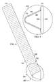
Figure 6 , an illustration of an isometric view oftuning object 312 separate fromblade 220 is depicted in accordance with an illustrative embodiment. As depicted, tuningobject 312 may include plurality ofsegments 600 separated by plurality ofslots 602. Plurality ofsegments 600 may be an example of one implementation for plurality ofsegments 126 inFigure 1 . Plurality ofslots 602 may be an example of one implementation for plurality ofslots 131 inFigure 1 . - In this illustrative example, plurality of
segments 600 may extend fromconnective segment 604. In particular, plurality ofsegments 600 andconnective segment 604 may have been formed from a same workpiece.Connective segment 604 may connect all of plurality ofsegments 600 together. Plurality ofsegments 600 may have been formed such thatconnective segment 604 and plurality ofsegments 600 together have a selected mass. An enlarged view ofportion 606 of tuningobject 312 is depicted inFigure 7 below. - With reference now to
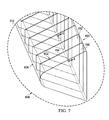
Figure 7 , an illustration of an enlarged isometric view ofportion 606 of tuningobject 312 fromFigure 6 is depicted in accordance with an illustrative embodiment. As depicted,segment 700 andsegment 702 may be examples of segments in plurality ofsegments 600.Segment 700 andsegment 702 may be separated byslot 704. Further,slot 704 may be an example of one of plurality ofslots 602. As depicted,slot 704 may not extend all the way through tuningobject 312. Rather, slot 704 may only extend up toconnective segment 604. - Turning now to
Figure 8 , an illustration ofportion 606 of tuningobject 312 fromFigure 7 taken along lines 8-8 inFigure 7 is depicted in accordance with an illustrative embodiment. In this illustrative example,segment 700 may havelength 800, whilesegment 702 may havelength 802.Length 800 andlength 802 may be substantially equal. In one illustrative example,length 800 andlength 802 may be about 0.4 inches. Each of plurality ofsegments 600 may have substantially the same length assegment 700 andsegment 702. - Further,
slot 704 may havelength 804.Length 804 may be about 0.005 inches in this illustrative example. Each of plurality ofslots 602 may have substantially the same length asslot 704. In other illustrative examples, the lengths of segments and/or slots in tuningobject 312 may be described as widths. - As depicted,
segment 700 may haveheight 806.Height 806 may be about 1.2 inches. Each of plurality ofsegments 600 may have substantially the same height assegment 700. Further,connective segment 604 may haveheight 808.Height 808 may be about 0.2 inches.Height 808 may be substantially constant along the length ofconnective segment 604 in this illustrative example. - With reference now to
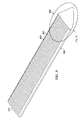
Figure 9 , an illustration of an isometric view oftuning object 314 separate fromblade 220 is depicted in accordance with an illustrative embodiment.Tuning object 314 may have a shape that is similar but different from tuningobject 312 inFigure 6 . - As depicted, tuning
object 314 may include plurality ofsegments 900 separated by plurality ofslots 902. Plurality ofsegments 900 may be an example of one implementation for plurality ofsegments 126 inFigure 1 . Plurality ofslots 902 may be an example of one implementation for plurality ofslots 131 inFigure 1 . - In this illustrative example, plurality of
segments 900 may extend fromconnective segment 904. In particular, plurality ofsegments 900 andconnective segment 904 may have been formed from a same workpiece.Connective segment 904 may connect all of plurality ofsegments 900 together. Plurality ofsegments 900 may have been formed such thatconnective segment 904 and plurality ofsegments 900 together have a selected mass. An enlarged view ofportion 906 of tuningobject 314 is depicted inFigure 10 below. - With reference now to
Figure 10 , an illustration of an enlarged isometric view ofportion 906 of tuningobject 314 fromFigure 9 is depicted in accordance with an illustrative embodiment. As depicted,segment 1000 andsegment 1002 may be examples of segments in plurality ofsegments 900.Segment 1000 andsegment 1002 may be separated byslot 1004. Further,slot 1004 may be an example of one of plurality ofslots 902. As depicted,slot 1004 may not extend all the way through tuningobject 314. Rather,slot 1004 may only extend up toconnective segment 904. - Turning now to
Figure 11 , an illustration ofportion 906 of tuningobject 314 taken along lines 11-11 inFigure 10 is depicted in accordance with an illustrative embodiment. In this illustrative example,segment 1000 may havelength 1100, whilesegment 1002 may havelength 1102.Length 1100 andlength 1102 may be substantially equal. In one illustrative example,length 1100 andlength 1102 may be about 0.4 inches. Each of plurality ofsegments 900 may have substantially the same length assegment 1000 andsegment 1002. - Further,
slot 1004 may havelength 1104.Length 1104 may be about 0.005 inches. Each of plurality ofslots 902 may have substantially the same length asslot 1004. - As depicted,
segment 1000 may haveheight 1106.Height 1106 may be about 1.2 inches. Each of plurality ofsegments 900 may have substantially the same height assegment 1000. Further,connective segment 904 may haveheight 1108.Height 1108 may be about 0.2 inches.Height 1108 may be substantially constant along the length ofconnective segment 904 in this illustrative example. - The illustrations of
rotorcraft 200 inFigure 2 ,section 222 ofblade 220 inFigures 3-4, section 404 ofblade 220 inFigure 5 , tuningobject 312 inFigures 6-8 , and tuningobject 314 inFigures 9-11 are not meant to imply physical or architectural limitations to the manner in which an illustrative embodiment may be implemented. Other components in addition to or in place of the ones illustrated may be used. Some components may be optional. - Additionally, some of the components in
Figures 2-11 may be illustrative examples of how components shown in block form inFigure 1 may be implemented as physical structures. The different components shown inFigures 2-11 may be combined with components inFigure 1 , used with components inFigure 1 , or a combination of the two. - With reference now to
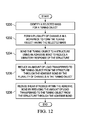
Figure 12 , an illustration of a process for reducing a vibratory response of a structure using a tuning object in the form of a flowchart is depicted in accordance with an illustrative embodiment. The process illustrated inFigure 12 may be implemented withinmanufacturing environment 100 inFigure 1 to reduce a vibratory response ofstructure 104 usingtuning object 102 inFigure 1 . - The process may begin by identifying selected
mass 114 for tuning object 102 (operation 1200). Thereafter, plurality ofchannels 130 may be formed inworkpiece 116 to form tuningobject 102 having selected mass 114 (operation 1202).Workpiece 116 may be comprised ofmaterial 120 havingdensity 122 within selectedrange 123. Inoperation 1202, plurality ofchannels 130 may be formed by removing portions ofmaterial 120 fromworkpiece 116 usingtool 124.Tool 124 may be, for example,electronic discharge machine 138. - The formation of plurality of
channels 130 may partiallysegment workpiece 116 into plurality ofsegments 126. The segments in plurality ofsegments 126 may be connected to each other byconnective segment 128, which may be the portion ofworkpiece 116 into which plurality ofchannels 130 do not extend. - Next, tuning
object 102 may be bonded to structure 104 usingadhesive bond 108 to reduce the vibratory response of structure 104 (operation 1204). Whenstructure 104 takes the form ofblade 110, tuningobject 102 may be bonded tocomposite structure 106 inblade 110 usingadhesive bond 108. - The amount of
load 135 transferred to tuning object 102 fromstructure 104 throughadhesive bond 108 may be reduced by plurality ofchannels 130 in tuning object 102 (operation 1206). Further, shear stresses 136 withinadhesive bond 108 may be reduced by reducing the amount ofload 135 transferred to tuning object 102 fromstructure 104 throughadhesive bond 108 may be reduced by plurality ofchannels 130 in tuning object 102 (operation 1208), with the process terminating thereafter. - For example, without limitation, when
structure 104 takes the form ofblade 110, bending ofblade 110 may causeload 135 to be generated, travel throughcomposite structure 106 inblade 110, and be transferred to tuningobject 102 throughadhesive bond 108. The amount ofload 135 transferred to tuningobject 102 throughadhesive bond 108 may be reduced by the reduction in the maximum length of continuous contact betweentuning object 102 andadhesive bond 108 caused by the formation of plurality ofchannels 130. - In this manner, the possibility of undesired inconsistencies forming within
adhesive bond 108 and/oradhesive bond 108 separating from tuningobject 102 and/orcomposite structure 106 may be reduced. The strength and integrity ofadhesive bond 108 may be maintained. - The flowcharts and block diagrams in the different depicted embodiments illustrate the architecture, functionality, and operation of some possible implementations of apparatus and methods in an illustrative embodiment. In this regard, each block in the flowcharts or block diagrams may represent a module, a segment, a function, and/or a portion of an operation or step.
- In some alternative implementations of an illustrative embodiment, the function or functions noted in the blocks may occur out of the order noted in the figures. For example, in some cases, two blocks shown in succession may be executed substantially concurrently, or the blocks may sometimes be performed in the reverse order, depending upon the functionality involved. Also, other blocks may be added in addition to the illustrated blocks in a flowchart or block diagram.
- In some illustrative embodiments, plurality of
segments 126 and/or plurality ofchannels 130 may be altered afteroperation 1202 inFigure 12 to change the mass of tuningobject 102. For example, without limitation, the length of one or more of plurality ofchannels 130 may be increased to reduce the mass of tuningobject 102. In another example, one or more of plurality ofsegments 126 may be removed or cut away to reduce the mass of tuningobject 102. - Illustrative embodiments of the disclosure may be described in the context of aircraft manufacturing and
service method 1300 as shown inFigure 13 androtorcraft 1400 as shown inFigure 14 . Turning first toFigure 13 , an illustration of an aircraft manufacturing and service method in the form of a block diagram is depicted in accordance with an illustrative embodiment. During pre-production, aircraft manufacturing andservice method 1300 may include specification anddesign 1302 ofrotorcraft 1400 inFigure 14 andmaterial procurement 1304. - During production, component and
subassembly manufacturing 1306 andsystem integration 1308 ofrotorcraft 1400 inFigure 14 takes place. Thereafter,rotorcraft 1400 inFigure 14 may go through certification anddelivery 1310 in order to be placed inservice 1312. While inservice 1312 by a customer,rotorcraft 1400 inFigure 14 is scheduled for routine maintenance andservice 1314, which may include modification, reconfiguration, refurbishment, and other maintenance or service. - Each of the processes of aircraft manufacturing and
service method 1300 may be performed or carried out by a system integrator, a third party, and/or an operator. In these examples, the operator may be a customer. For the purposes of this description, a system integrator may include, without limitation, any number of aircraft manufacturers and major-system subcontractors; a third party may include, without limitation, any number of vendors, subcontractors, and suppliers; and an operator may be an airline, a leasing company, a military entity, a service organization, and so on. - With reference now to
Figure 14 , an illustration of a rotorcraft in the form of a block diagram is depicted in which an illustrative embodiment may be implemented. In this example,rotorcraft 1400 is produced by aircraft manufacturing andservice method 1300 inFigure 13 and may includeairframe 1402 with plurality ofsystems 1404 and interior 1406. Examples ofsystems 1404 include one or more ofpropulsion system 1408,electrical system 1410,hydraulic system 1412,environmental system 1414, androtor system 1416.Rotor system 1416 may comprise plurality ofblades 1418. Any number of other systems may be included. Although an aerospace example is shown, different illustrative embodiments may be applied to other industries, such as the automotive industry or the marine industry. - Apparatuses and methods embodied herein may be employed during at least one of the stages of aircraft manufacturing and
service method 1300 inFigure 13 . For example, without limitation, tuningobject 102 fromFigure 1 may be installed within a blade in plurality ofblades 1418.Tuning object 102 may be formed and installed in the blade during component andsubassembly manufacturing 1306,system integration 1308, and/or routine maintenance andservice 1314 inFigure 13 . - In one illustrative example, components or subassemblies produced in component and
subassembly manufacturing 1306 inFigure 13 may be fabricated or manufactured in a manner similar to components or subassemblies produced whilerotorcraft 1400 is inservice 1312 inFigure 13 . As yet another example, one or more apparatus embodiments, method embodiments, or a combination thereof may be utilized during production stages, such as component andsubassembly manufacturing 1306 andsystem integration 1308 inFigure 13 . One or more apparatus embodiments, method embodiments, or a combination thereof may be utilized whilerotorcraft 1400 is inservice 1312 and/or during maintenance andservice 1314 inFigure 13 . The use of a number of the different illustrative embodiments may substantially expedite the assembly of and/or reduce the cost ofrotorcraft 1400. - Thus, the different illustrative embodiments provide a tuning object, such as
tuning object 102 inFigure 1 , which may be used to tune the mass of a foil, such asstructure 104 inFigure 1 . Any number of tuning objects implemented in a manner similar to tuningobject 102 inFigure 1 may be used to tune the mass of the foil. Further, these tuning objects may be installed at various locations along the foil to adjust the position of the center of gravity of the foil relative to a pitch axis or some other axis through the foil. The tuning object described by the illustrative embodiments may be easier to install in a blade than a plurality of cylindrical weights. - Further, the disclosure comprises embodiments according to the following clauses:
- (1) An apparatus comprising: a tuning object configured to be bonded to a structure to reduce a vibratory response of the structure in which the tuning object has a plurality of channels formed such that the tuning object has a selected mass.
- (2) The apparatus of
clause 1, wherein the tuning object is configured to be bonded to the structure by an adhesive bond and wherein the plurality of channels is configured to reduce an amount of load transferred to the tuning object from the structure through the adhesive bond. - (3) The apparatus of clause 2, wherein the plurality of channels is configured to reduce a maximum length of continuous contact between the tuning object and the adhesive bond such that the amount of load transferred to the tuning object from the structure through the adhesive bond is reduced.
- (4) The apparatus of clause 2, wherein the plurality of channels is configured to reduce the amount of load transferred to the tuning object from the structure through the adhesive bond such that shear stresses within the adhesive bond are reduced to within selected tolerances.
- (5) The apparatus of
clause 1, wherein the tuning object comprises a plurality of segments separated by the plurality of channels; anda connective segment configured to connect segments in the plurality of segments to each other. - (6) The apparatus of clause 5, wherein the plurality of segments is monolithic with the connective segment.
- (7) The apparatus of
clause 1, wherein the plurality of channels is formed in a workpiece using a tool to form the tuning object having the selected mass. - (8) The apparatus of clause 7, wherein the workpiece is comprised of a material having a density within a selected range.
- (9) The apparatus of
clause 8, wherein the material is selected from one of tungsten and tantalum. - (10) The apparatus of clause 7, wherein the tool is an electronic discharge machine.
- (11) The apparatus of
clause 1 further comprising the structure, wherein the structure is a rotor blade for a rotorcraft. - (12) The apparatus of clause 11 further comprising an adhesive bond configured to bond the tuning object to the rotor blade, wherein the adhesive bond comprises a layer of adhesive material.
- (13) The apparatus of clause 12, wherein the adhesive bond is configured to bond the tuning object to a composite structure in the rotor blade.
- (14) A rotor blade for a rotorcraft, the rotor blade comprising a composite structure; a tuning object configured to be attached to the composite structure to reduce a vibratory response of the rotor blade in which the tuning object has a plurality of channels formed such that the tuning object has a selected mass and in which the tuning object comprises a plurality of segments separated by the plurality of channels; and a connective segment configured to connect segments in the plurality of segments to each other in which the plurality of segments is monolithic with the connective segment; andan adhesive bond configured to bond the tuning object to the composite structure in which the plurality of channels is configured to reduce an amount of load transferred to the tuning object from the composite structure through the adhesive bond such that shear stresses in the adhesive bond are reduced to within selected tolerances.
- (15) A method for reducing a vibratory response in a structure using a tuning object, the method comprising identifying a selected mass for the tuning object;forming a plurality of channels in a workpiece having a mass greater than the selected mass to form the tuning object having the selected mass; and bonding the tuning object to the structure using an adhesive bond to reduce the vibratory response of the structure.
- (16) The method of clause 15 further comprising reducing an amount of load transferred to the tuning object from the structure through the adhesive bond by the plurality of channels.
- (17) The method of clause 16 further comprising reducing shear stresses within the adhesive bond by reducing the amount of load transferred to the tuning object from the structure through the adhesive bond.
- (18) The method of clause 15, wherein the step of forming the plurality of channels in the workpiece having the mass greater than the selected mass to form the tuning object having the selected mass comprises: removing portions of material from the workpiece to form the plurality of channels, wherein removing the portions of the material from the workpiece reduces the mass of the workpiece.
- (19) The method of clause 18, wherein the step of forming the plurality of channels in the workpiece having the mass greater than the selected mass to form the tuning object having the selected mass further comprises: determining whether the workpiece having the plurality of channels has the selected mass within selected tolerances; and responsive to a determination that the workpiece having the plurality of channels does not have the selected mass within the selected tolerances, removing additional material from the workpiece around at least one of the plurality of channels to reduce the mass of the workpiece to the selected mass.
- (20) The method of clause 18, wherein the step of removing the portions of material from the workpiece to form the plurality of channels comprises: removing portions of material from the workpiece using an electronic discharge machine to form the plurality of channels.
- (21) The method of clause 15, wherein the step of forming the plurality of channels in the workpiece having the mass greater than the selected mass to form the tuning object having the selected mass comprises: identifying a length for each of the plurality of channels to be formed based on the selected mass; and forming the plurality of channels such that each channel in the plurality of channels has the length identified.
- (22) The method of clause 15, wherein the step of forming the plurality of channels in the workpiece having the mass greater than the selected mass to form the tuning object having the selected mass comprises: forming the plurality of channels in the workpiece such that the workpiece is partially segmented into a plurality of segments in which segments in the plurality of segments are connected to each other by a connective segment.
- (23) The method of clause 22, wherein the step of forming the plurality of channels in the workpiece having the mass greater than the selected mass to form the tuning object having the selected mass further comprises: identifying a length for each of the plurality of segments based on the selected mass identified; and forming the plurality of channels in the workpiece such that the workpiece is partially segmented into the plurality of segments in which each segment in the plurality of segments has the length identified.
- (24) The method of clause 15, wherein the step of bonding the tuning object to the structure using the adhesive bond comprises applying a layer of adhesive material onto a surface of the structure; placing the tuning object over the layer of adhesive material; andcuring the layer of adhesive material to form the adhesive bond between the tuning object and the structure.
- (25) The method of clause 24, wherein the step of bonding the tuning object to the structure using the adhesive bond further comprises: applying an additional layer of adhesive material over the tuning object such that the additional layer of adhesive material covers the tuning object and a portion of the surface of the structure; placing a laminate wrap over the additional layer of adhesive material; and curing the additional layer of adhesive material to bond the laminate wrap to the tuning object and the structure, wherein the laminate wrap holds the tuning object in place relative to the structure.
- (26) A method for reducing a vibratory response of a rotor blade for a rotorcraft using a tuning object, the method comprising: identifying a selected mass for the tuning object; forming a plurality of channels in a workpiece comprised of a material having a density within a selected range by removing portions of material from the workpiece using an electronic discharge machine to form the tuning object having the selected mass; bonding the tuning object to a composite structure in the rotor blade using an adhesive bond to reduce the vibratory response of the rotor blade; reducing an amount of load transferred to the tuning object from the composite structure through the adhesive bond by the plurality of channels in the tuning object; and reducing shear stresses within the adhesive bond by reducing the amount of load transferred to the tuning object from the composite structure through the adhesive bond.
- The description of the different illustrative embodiments has been presented for purposes of illustration and description, and is not intended to be exhaustive or limited to the embodiments in the form disclosed. Many modifications and variations will be apparent to those of ordinary skill in the art. Further, different illustrative embodiments may provide different features as compared to other illustrative embodiments. The embodiment or embodiments selected are chosen and described in order to best explain the principles of the embodiments, the practical application, and to enable others of ordinary skill in the art to understand the disclosure for various embodiments with various modifications as are suited to the particular use contemplated.
Claims (15)
- Apparatus comprising:a tuning object (102) configured to be bonded to a structure (104) to reduce a vibratory response of the structure (104) in which the tuning object (102) has a plurality of channels (130) formed such that the tuning object (102) has a selected mass (114).
- Apparatus of claim 1, wherein the tuning object (102) is configured to be bonded to the structure (104) by an adhesive bond (108) and wherein the plurality of channels (130) is configured to reduce an amount of load (135) transferred to the tuning object (102) from the structure (104) through the adhesive bond (108).
- Apparatus of any preceding claim, wherein the plurality of channels (130) is configured to reduce a maximum length of continuous contact between the tuning object (102) and an adhesive bond (108) such that an amount of load (135) transferred to the tuning object (102) from the structure (104) through the adhesive bond (108) is reduced.
- Apparatus of any preceding claim, wherein the plurality of channels (130) is configured to reduce an amount of load (135) transferred to the tuning object (102) from the structure (104) through an adhesive bond (108) such that shear stresses (136) within the adhesive bond (108) are reduced to within selected tolerances.
- Apparatus of any preceding claim, wherein the tuning object (102) comprises:a plurality of segments (126) separated by the plurality of channels (130); anda connective segment (128) configured to connect segments in the plurality of segments (126) to each other, wherein the plurality of segments (126) is monolithic with the connective segment (128).
- Apparatus of any preceding claim, wherein the plurality of channels (130) is formed in a workpiece (116) using a tool (124) to form the tuning object (102) having the selected mass (114); wherein the workpiece (116) is comprised of a material (120) having a density (122) within a selected range, wherein the material (120) is selected from one of tungsten and tantalum; and wherein the tool (124) is an electronic discharge machine (138).
- Apparatus of any preceding claim further comprising:the structure (104), wherein the structure (104) is a rotor blade for a rotorcraft (112; wherein an adhesive bond (108) is configured to bond the tuning object (102) to:the rotor blade, anda composite structure (106) in the rotor blade; and wherein the adhesive bond (108) comprises a layer of adhesive material.
- Method for reducing a vibratory response in a structure (104) using a tuning object (102), the method comprising:identifying a selected mass (114) for the tuning object (102);forming a plurality of channels (130) in a workpiece (116) having a mass greater than the selected mass (114) to form the tuning object (102) having the selected mass (114); andbonding the tuning object (102) to the structure (104) using an adhesive bond (108) to reduce the vibratory response of the structure (104).
- Method of claim 8 further comprising:reducing an amount of load (135) transferred to the tuning object (102) from the structure (104) through the adhesive bond (108) by the plurality of channels (130); andreducing shear stresses (136) within the adhesive bond (108) by reducing the amount of load (135) transferred to the tuning object (102) from the structure (104) through the adhesive bond (108).
- Method of any of claims 8 to 9, wherein the step of forming the plurality of channels (130) in the workpiece (116) having the mass greater than the selected mass (114) to form the tuning object (102) having the selected mass (114) comprises:removing portions of material (120) from the workpiece (116) to form the plurality of channels (130), wherein removing the portions of the material (120) from the workpiece (116) reduces the mass of the workpiece (116);determining whether the workpiece (116) having the plurality of channels (130) has the selected mass (114) within selected tolerances; andresponsive to a determination that the workpiece (116) having the plurality of channels (130) does not have the selected mass (114) within the selected tolerances, removing additional material from the workpiece (116) around at least one of the plurality of channels (130) to reduce the mass of the workpiece (116) to the selected mass (114).
- Method of claim 10, wherein the step of removing the portions of material (120) from the workpiece (116) to form the plurality of channels (130) comprises:removing portions of material (120) from the workpiece (116) using an electronic discharge machine (138) to form the plurality of channels (130).
- Method of any of claims 8 to 11, wherein the step of forming the plurality of channels (130) in the workpiece (116) having the mass greater than the selected mass (114) to form the tuning object (102) having the selected mass (114) comprises:identifying a length for each of the plurality of channels (130) to be formed based on the selected mass (114); andforming the plurality of channels (130) such that each channel in the plurality of channels (130) has the length identified.
- Method of any of claims 8 to 12, wherein the step of forming the plurality of channels (130) in the workpiece (116) having the mass greater than the selected mass (114) to form the tuning object (102) having the selected mass (114) comprises:forming the plurality of channels (130) in the workpiece (116) such that the workpiece (116) is partially segmented into a plurality of segments (126) in which segments in the plurality of segments (126) are connected to each other by a connective segment (128);identifying a length for each of the plurality of segments (126) based on the selected mass (114) identified; andforming the plurality of channels (130) in the workpiece (116) such that the workpiece (116) is partially segmented into the plurality of segments (126) in which each segment in the plurality of segments (126) has the length identified.
- Method of any of claims 8 to 13, wherein the step of bonding the tuning object (102) to the structure (104) using the adhesive bond (108) comprises:applying a layer of adhesive material onto a surface of the structure (104);placing the tuning object (102) over the layer of adhesive material; andcuring the layer of adhesive material to form the adhesive bond (108) between the tuning object (102) and the structure (104).
- Method of claim 14, wherein the step of bonding the tuning object (102) to the structure (104) using the adhesive bond (108) further comprises:applying an additional layer of adhesive material over the tuning object (102) such that the additional layer of adhesive material covers the tuning object (102) and a portion of the surface of the structure (104);placing a laminate wrap (316) over the additional layer of adhesive material; andcuring the additional layer of adhesive material to bond the laminate wrap (316) to the tuning object (102) and the structure (104), wherein the laminate wrap (316) holds the tuning object (102) in place relative to the structure (104).
Applications Claiming Priority (1)
| Application Number | Priority Date | Filing Date | Title |
|---|---|---|---|
| US13/676,503 US9249851B2 (en) | 2012-11-14 | 2012-11-14 | Apparatus and method for tuning a vibratory response of a rotor blade |
Publications (3)
| Publication Number | Publication Date |
|---|---|
| EP2733067A2 true EP2733067A2 (en) | 2014-05-21 |
| EP2733067A3 EP2733067A3 (en) | 2016-07-13 |
| EP2733067B1 EP2733067B1 (en) | 2019-10-09 |
Family
ID=49518671
Family Applications (1)
| Application Number | Title | Priority Date | Filing Date |
|---|---|---|---|
| EP13190176.1A Active EP2733067B1 (en) | 2012-11-14 | 2013-10-25 | Apparatus and method for tuning a vibratory response of a rotor blade |
Country Status (3)
| Country | Link |
|---|---|
| US (1) | US9249851B2 (en) |
| EP (1) | EP2733067B1 (en) |
| JP (1) | JP5818862B2 (en) |
Families Citing this family (4)
| Publication number | Priority date | Publication date | Assignee | Title |
|---|---|---|---|---|
| US10239604B2 (en) * | 2016-05-21 | 2019-03-26 | Bell Helicopter Textron Inc. | Structurally biased proprotor blade assembly |
| US11891169B2 (en) * | 2019-09-06 | 2024-02-06 | Textron Innovations Inc. | Insert for a blade of a rotary-wing aircraft |
| US20210078699A1 (en) * | 2019-09-18 | 2021-03-18 | Bell Textron Inc. | Insert for a blade of a rotary-wing aircraft and a blade of rotary-wing aircraft |
| US11254424B2 (en) | 2019-09-30 | 2022-02-22 | Textron Innovations Inc. | Balance weight assemblies for rotor blades |
Family Cites Families (19)
| Publication number | Priority date | Publication date | Assignee | Title |
|---|---|---|---|---|
| US3105557A (en) * | 1960-08-04 | 1963-10-01 | Wigal Voorhis Frederick | Rotor blade |
| US3237697A (en) * | 1963-02-11 | 1966-03-01 | Boeing Co | Helicopter rotor blade |
| US3323597A (en) * | 1965-02-01 | 1967-06-06 | United Aircraft Corp | Bonded counterweight for blade of rotary wing aircraft |
| US3508843A (en) * | 1968-08-01 | 1970-04-28 | Lockheed Aircraft Corp | Antinode weight assembly for rotor blades |
| US3574484A (en) | 1969-05-14 | 1971-04-13 | Harold R Lamb Jr | Rotor blade heavy core tuning weight |
| US3812724A (en) * | 1969-09-19 | 1974-05-28 | M Matson | Rotational balancer |
| US4150920A (en) * | 1977-12-02 | 1979-04-24 | The United States Of America As Represented By The Secretary Of The Army | Rotor blade tipweight assembly |
| DE2816561C3 (en) * | 1978-04-17 | 1981-10-15 | Krupp Stahl Ag, 4630 Bochum | System of rail wheel and track for rail vehicles |
| US5346367A (en) * | 1984-12-21 | 1994-09-13 | United Technologies Corporation | Advanced composite rotor blade |
| US5273398A (en) * | 1992-12-01 | 1993-12-28 | United Technologies Corporation | Rotor blade balance weight assembly |
| US5430937A (en) * | 1994-07-15 | 1995-07-11 | United Technologies Corporation | Apparatus and methods for fabricating a helicopter main rotor blade |
| FR2781196B1 (en) * | 1998-07-17 | 2000-09-15 | Eurocopter France | ROTOR BLADE OF A GIRAVION WITH A STATIC AND DYNAMIC BALANCING DEVICE AND A METHOD OF BALANCING A BLADE |
| JP2001116082A (en) * | 1999-10-15 | 2001-04-27 | Tokai Rubber Ind Ltd | Vibration control device for building structures |
| JP2001193788A (en) * | 1999-12-31 | 2001-07-17 | Inter Seiko Co Ltd | Method of manufacturing weight for dynamic damper |
| JP2003004093A (en) * | 2001-06-20 | 2003-01-08 | Hosei Brake Ind Ltd | Manufacturing method of damper weight and damper weight |
| US7097427B2 (en) | 2002-08-02 | 2006-08-29 | Bell Helicopter Textron Inc. | Helicopter main rotor blade balance weight retention assembly |
| EP1477703A3 (en) * | 2003-05-12 | 2004-12-15 | Lucchesi Creations S.A. | Balance weight for vehicle wheel |
| JP4203109B2 (en) * | 2005-12-09 | 2008-12-24 | 株式会社アライドマテリアル | Mass body for vibration control |
| US8029240B2 (en) | 2007-11-08 | 2011-10-04 | The Boeing Company | Rotor blade adjustable weight retention system |
-
2012
- 2012-11-14 US US13/676,503 patent/US9249851B2/en active Active
-
2013
- 2013-10-25 EP EP13190176.1A patent/EP2733067B1/en active Active
- 2013-11-12 JP JP2013233688A patent/JP5818862B2/en active Active
Non-Patent Citations (1)
| Title |
|---|
| None |
Also Published As
| Publication number | Publication date |
|---|---|
| EP2733067B1 (en) | 2019-10-09 |
| US9249851B2 (en) | 2016-02-02 |
| JP2014111986A (en) | 2014-06-19 |
| US20140133993A1 (en) | 2014-05-15 |
| JP5818862B2 (en) | 2015-11-18 |
| EP2733067A3 (en) | 2016-07-13 |
Similar Documents
| Publication | Publication Date | Title |
|---|---|---|
| US9015941B2 (en) | Method of repairing honeycomb core using pourable structural foam | |
| US8114329B2 (en) | Wing and blade structure using pultruded composites | |
| US5542820A (en) | Engineered ceramic components for the leading edge of a helicopter rotor blade | |
| US9149999B2 (en) | Method of repairing, splicing, joining, machining, and stabilizing honeycomb core using pourable structural foam and a structure incorporating the same | |
| US9334039B2 (en) | Composite laminate structure | |
| EP2292709A2 (en) | Bonded assemblies and methods for improving bond strength of a joint | |
| EP2733067B1 (en) | Apparatus and method for tuning a vibratory response of a rotor blade | |
| EP3378766B1 (en) | Adaptable rotor blade design for performance flexibility | |
| EP2727697B1 (en) | Method of stabilizing honeycomb core using pourable structural foam | |
| US20170182738A1 (en) | Composite Filler | |
| US10668705B2 (en) | Joining structural members using foam | |
| EP2597033B1 (en) | Composite propeller spar | |
| EP2727696B1 (en) | Method of splicing together a first core member and a second core member using a pourable structural foam | |
| EP2727698B1 (en) | Method of machining and stabilizing a core member with cells using pourable structural foam | |
| US11891169B2 (en) | Insert for a blade of a rotary-wing aircraft |
Legal Events
| Date | Code | Title | Description |
|---|---|---|---|
| PUAI | Public reference made under article 153(3) epc to a published international application that has entered the european phase |
Free format text: ORIGINAL CODE: 0009012 |
|
| 17P | Request for examination filed |
Effective date: 20131025 |
|
| AK | Designated contracting states |
Kind code of ref document: A2 Designated state(s): AL AT BE BG CH CY CZ DE DK EE ES FI FR GB GR HR HU IE IS IT LI LT LU LV MC MK MT NL NO PL PT RO RS SE SI SK SM TR |
|
| AX | Request for extension of the european patent |
Extension state: BA ME |
|
| PUAL | Search report despatched |
Free format text: ORIGINAL CODE: 0009013 |
|
| AK | Designated contracting states |
Kind code of ref document: A3 Designated state(s): AL AT BE BG CH CY CZ DE DK EE ES FI FR GB GR HR HU IE IS IT LI LT LU LV MC MK MT NL NO PL PT RO RS SE SI SK SM TR |
|
| AX | Request for extension of the european patent |
Extension state: BA ME |
|
| RIC1 | Information provided on ipc code assigned before grant |
Ipc: B64C 27/473 20060101ALN20160603BHEP Ipc: B64C 27/00 20060101AFI20160603BHEP |
|
| STAA | Information on the status of an ep patent application or granted ep patent |
Free format text: STATUS: REQUEST FOR EXAMINATION WAS MADE |
|
| R17P | Request for examination filed (corrected) |
Effective date: 20170111 |
|
| RBV | Designated contracting states (corrected) |
Designated state(s): AL AT BE BG CH CY CZ DE DK EE ES FI FR GB GR HR HU IE IS IT LI LT LU LV MC MK MT NL NO PL PT RO RS SE SI SK SM TR |
|
| GRAP | Despatch of communication of intention to grant a patent |
Free format text: ORIGINAL CODE: EPIDOSNIGR1 |
|
| RIC1 | Information provided on ipc code assigned before grant |
Ipc: B64C 27/00 20060101AFI20190318BHEP Ipc: B64C 27/473 20060101ALN20190318BHEP |
|
| STAA | Information on the status of an ep patent application or granted ep patent |
Free format text: STATUS: GRANT OF PATENT IS INTENDED |
|
| INTG | Intention to grant announced |
Effective date: 20190425 |
|
| GRAS | Grant fee paid |
Free format text: ORIGINAL CODE: EPIDOSNIGR3 |
|
| GRAA | (expected) grant |
Free format text: ORIGINAL CODE: 0009210 |
|
| STAA | Information on the status of an ep patent application or granted ep patent |
Free format text: STATUS: THE PATENT HAS BEEN GRANTED |
|
| AK | Designated contracting states |
Kind code of ref document: B1 Designated state(s): AL AT BE BG CH CY CZ DE DK EE ES FI FR GB GR HR HU IE IS IT LI LT LU LV MC MK MT NL NO PL PT RO RS SE SI SK SM TR |
|
| REG | Reference to a national code |
Ref country code: GB Ref legal event code: FG4D |
|
| REG | Reference to a national code |
Ref country code: CH Ref legal event code: EP |
|
| REG | Reference to a national code |
Ref country code: DE Ref legal event code: R096 Ref document number: 602013061401 Country of ref document: DE |
|
| REG | Reference to a national code |
Ref country code: IE Ref legal event code: FG4D |
|
| REG | Reference to a national code |
Ref country code: AT Ref legal event code: REF Ref document number: 1188499 Country of ref document: AT Kind code of ref document: T Effective date: 20191115 |
|
| REG | Reference to a national code |
Ref country code: NL Ref legal event code: MP Effective date: 20191009 |
|
| REG | Reference to a national code |
Ref country code: LT Ref legal event code: MG4D |
|
| REG | Reference to a national code |
Ref country code: AT Ref legal event code: MK05 Ref document number: 1188499 Country of ref document: AT Kind code of ref document: T Effective date: 20191009 |
|
| PG25 | Lapsed in a contracting state [announced via postgrant information from national office to epo] |
Ref country code: GR Free format text: LAPSE BECAUSE OF FAILURE TO SUBMIT A TRANSLATION OF THE DESCRIPTION OR TO PAY THE FEE WITHIN THE PRESCRIBED TIME-LIMIT Effective date: 20200110 Ref country code: BG Free format text: LAPSE BECAUSE OF FAILURE TO SUBMIT A TRANSLATION OF THE DESCRIPTION OR TO PAY THE FEE WITHIN THE PRESCRIBED TIME-LIMIT Effective date: 20200109 Ref country code: FI Free format text: LAPSE BECAUSE OF FAILURE TO SUBMIT A TRANSLATION OF THE DESCRIPTION OR TO PAY THE FEE WITHIN THE PRESCRIBED TIME-LIMIT Effective date: 20191009 Ref country code: AT Free format text: LAPSE BECAUSE OF FAILURE TO SUBMIT A TRANSLATION OF THE DESCRIPTION OR TO PAY THE FEE WITHIN THE PRESCRIBED TIME-LIMIT Effective date: 20191009 Ref country code: LT Free format text: LAPSE BECAUSE OF FAILURE TO SUBMIT A TRANSLATION OF THE DESCRIPTION OR TO PAY THE FEE WITHIN THE PRESCRIBED TIME-LIMIT Effective date: 20191009 Ref country code: PL Free format text: LAPSE BECAUSE OF FAILURE TO SUBMIT A TRANSLATION OF THE DESCRIPTION OR TO PAY THE FEE WITHIN THE PRESCRIBED TIME-LIMIT Effective date: 20191009 Ref country code: NO Free format text: LAPSE BECAUSE OF FAILURE TO SUBMIT A TRANSLATION OF THE DESCRIPTION OR TO PAY THE FEE WITHIN THE PRESCRIBED TIME-LIMIT Effective date: 20200109 Ref country code: NL Free format text: LAPSE BECAUSE OF FAILURE TO SUBMIT A TRANSLATION OF THE DESCRIPTION OR TO PAY THE FEE WITHIN THE PRESCRIBED TIME-LIMIT Effective date: 20191009 Ref country code: LV Free format text: LAPSE BECAUSE OF FAILURE TO SUBMIT A TRANSLATION OF THE DESCRIPTION OR TO PAY THE FEE WITHIN THE PRESCRIBED TIME-LIMIT Effective date: 20191009 Ref country code: SE Free format text: LAPSE BECAUSE OF FAILURE TO SUBMIT A TRANSLATION OF THE DESCRIPTION OR TO PAY THE FEE WITHIN THE PRESCRIBED TIME-LIMIT Effective date: 20191009 Ref country code: ES Free format text: LAPSE BECAUSE OF FAILURE TO SUBMIT A TRANSLATION OF THE DESCRIPTION OR TO PAY THE FEE WITHIN THE PRESCRIBED TIME-LIMIT Effective date: 20191009 Ref country code: PT Free format text: LAPSE BECAUSE OF FAILURE TO SUBMIT A TRANSLATION OF THE DESCRIPTION OR TO PAY THE FEE WITHIN THE PRESCRIBED TIME-LIMIT Effective date: 20200210 |
|
| PG25 | Lapsed in a contracting state [announced via postgrant information from national office to epo] |
Ref country code: IS Free format text: LAPSE BECAUSE OF FAILURE TO SUBMIT A TRANSLATION OF THE DESCRIPTION OR TO PAY THE FEE WITHIN THE PRESCRIBED TIME-LIMIT Effective date: 20200224 Ref country code: HR Free format text: LAPSE BECAUSE OF FAILURE TO SUBMIT A TRANSLATION OF THE DESCRIPTION OR TO PAY THE FEE WITHIN THE PRESCRIBED TIME-LIMIT Effective date: 20191009 Ref country code: RS Free format text: LAPSE BECAUSE OF FAILURE TO SUBMIT A TRANSLATION OF THE DESCRIPTION OR TO PAY THE FEE WITHIN THE PRESCRIBED TIME-LIMIT Effective date: 20191009 |
|
| REG | Reference to a national code |
Ref country code: CH Ref legal event code: PL |
|
| PG25 | Lapsed in a contracting state [announced via postgrant information from national office to epo] |
Ref country code: AL Free format text: LAPSE BECAUSE OF FAILURE TO SUBMIT A TRANSLATION OF THE DESCRIPTION OR TO PAY THE FEE WITHIN THE PRESCRIBED TIME-LIMIT Effective date: 20191009 |
|
| REG | Reference to a national code |
Ref country code: DE Ref legal event code: R097 Ref document number: 602013061401 Country of ref document: DE |
|
| PG2D | Information on lapse in contracting state deleted |
Ref country code: IS |
|
| PG25 | Lapsed in a contracting state [announced via postgrant information from national office to epo] |
Ref country code: EE Free format text: LAPSE BECAUSE OF FAILURE TO SUBMIT A TRANSLATION OF THE DESCRIPTION OR TO PAY THE FEE WITHIN THE PRESCRIBED TIME-LIMIT Effective date: 20191009 Ref country code: RO Free format text: LAPSE BECAUSE OF FAILURE TO SUBMIT A TRANSLATION OF THE DESCRIPTION OR TO PAY THE FEE WITHIN THE PRESCRIBED TIME-LIMIT Effective date: 20191009 Ref country code: CZ Free format text: LAPSE BECAUSE OF FAILURE TO SUBMIT A TRANSLATION OF THE DESCRIPTION OR TO PAY THE FEE WITHIN THE PRESCRIBED TIME-LIMIT Effective date: 20191009 Ref country code: LU Free format text: LAPSE BECAUSE OF NON-PAYMENT OF DUE FEES Effective date: 20191025 Ref country code: MC Free format text: LAPSE BECAUSE OF FAILURE TO SUBMIT A TRANSLATION OF THE DESCRIPTION OR TO PAY THE FEE WITHIN THE PRESCRIBED TIME-LIMIT Effective date: 20191009 Ref country code: DK Free format text: LAPSE BECAUSE OF FAILURE TO SUBMIT A TRANSLATION OF THE DESCRIPTION OR TO PAY THE FEE WITHIN THE PRESCRIBED TIME-LIMIT Effective date: 20191009 Ref country code: CH Free format text: LAPSE BECAUSE OF NON-PAYMENT OF DUE FEES Effective date: 20191031 Ref country code: LI Free format text: LAPSE BECAUSE OF NON-PAYMENT OF DUE FEES Effective date: 20191031 Ref country code: IS Free format text: LAPSE BECAUSE OF FAILURE TO SUBMIT A TRANSLATION OF THE DESCRIPTION OR TO PAY THE FEE WITHIN THE PRESCRIBED TIME-LIMIT Effective date: 20200209 |
|
| REG | Reference to a national code |
Ref country code: BE Ref legal event code: MM Effective date: 20191031 |
|
| PLBE | No opposition filed within time limit |
Free format text: ORIGINAL CODE: 0009261 |
|
| STAA | Information on the status of an ep patent application or granted ep patent |
Free format text: STATUS: NO OPPOSITION FILED WITHIN TIME LIMIT |
|
| PG25 | Lapsed in a contracting state [announced via postgrant information from national office to epo] |
Ref country code: SM Free format text: LAPSE BECAUSE OF FAILURE TO SUBMIT A TRANSLATION OF THE DESCRIPTION OR TO PAY THE FEE WITHIN THE PRESCRIBED TIME-LIMIT Effective date: 20191009 Ref country code: BE Free format text: LAPSE BECAUSE OF NON-PAYMENT OF DUE FEES Effective date: 20191031 Ref country code: SK Free format text: LAPSE BECAUSE OF FAILURE TO SUBMIT A TRANSLATION OF THE DESCRIPTION OR TO PAY THE FEE WITHIN THE PRESCRIBED TIME-LIMIT Effective date: 20191009 |
|
| 26N | No opposition filed |
Effective date: 20200710 |
|
| PG25 | Lapsed in a contracting state [announced via postgrant information from national office to epo] |
Ref country code: IE Free format text: LAPSE BECAUSE OF NON-PAYMENT OF DUE FEES Effective date: 20191025 |
|
| PG25 | Lapsed in a contracting state [announced via postgrant information from national office to epo] |
Ref country code: SI Free format text: LAPSE BECAUSE OF FAILURE TO SUBMIT A TRANSLATION OF THE DESCRIPTION OR TO PAY THE FEE WITHIN THE PRESCRIBED TIME-LIMIT Effective date: 20191009 |
|
| PG25 | Lapsed in a contracting state [announced via postgrant information from national office to epo] |
Ref country code: CY Free format text: LAPSE BECAUSE OF FAILURE TO SUBMIT A TRANSLATION OF THE DESCRIPTION OR TO PAY THE FEE WITHIN THE PRESCRIBED TIME-LIMIT Effective date: 20191009 |
|
| PG25 | Lapsed in a contracting state [announced via postgrant information from national office to epo] |
Ref country code: HU Free format text: LAPSE BECAUSE OF FAILURE TO SUBMIT A TRANSLATION OF THE DESCRIPTION OR TO PAY THE FEE WITHIN THE PRESCRIBED TIME-LIMIT; INVALID AB INITIO Effective date: 20131025 Ref country code: MT Free format text: LAPSE BECAUSE OF FAILURE TO SUBMIT A TRANSLATION OF THE DESCRIPTION OR TO PAY THE FEE WITHIN THE PRESCRIBED TIME-LIMIT Effective date: 20191009 |
|
| PG25 | Lapsed in a contracting state [announced via postgrant information from national office to epo] |
Ref country code: MK Free format text: LAPSE BECAUSE OF FAILURE TO SUBMIT A TRANSLATION OF THE DESCRIPTION OR TO PAY THE FEE WITHIN THE PRESCRIBED TIME-LIMIT Effective date: 20191009 |
|
| P01 | Opt-out of the competence of the unified patent court (upc) registered |
Effective date: 20230516 |
|
| PGFP | Annual fee paid to national office [announced via postgrant information from national office to epo] |
Ref country code: DE Payment date: 20251029 Year of fee payment: 13 |
|
| PGFP | Annual fee paid to national office [announced via postgrant information from national office to epo] |
Ref country code: GB Payment date: 20251027 Year of fee payment: 13 |
|
| PGFP | Annual fee paid to national office [announced via postgrant information from national office to epo] |
Ref country code: IT Payment date: 20251021 Year of fee payment: 13 |
|
| PGFP | Annual fee paid to national office [announced via postgrant information from national office to epo] |
Ref country code: FR Payment date: 20251027 Year of fee payment: 13 |
|
| PGFP | Annual fee paid to national office [announced via postgrant information from national office to epo] |
Ref country code: TR Payment date: 20251007 Year of fee payment: 13 |