EP2732928B1 - Redundant Delta manipulator - Google Patents
Redundant Delta manipulator Download PDFInfo
- Publication number
- EP2732928B1 EP2732928B1 EP13466027.3A EP13466027A EP2732928B1 EP 2732928 B1 EP2732928 B1 EP 2732928B1 EP 13466027 A EP13466027 A EP 13466027A EP 2732928 B1 EP2732928 B1 EP 2732928B1
- Authority
- EP
- European Patent Office
- Prior art keywords
- parallelograms
- platform
- arms
- joints
- manipulator
- Prior art date
- Legal status (The legal status is an assumption and is not a legal conclusion. Google has not performed a legal analysis and makes no representation as to the accuracy of the status listed.)
- Not-in-force
Links
Images


Classifications
-
- B—PERFORMING OPERATIONS; TRANSPORTING
- B25—HAND TOOLS; PORTABLE POWER-DRIVEN TOOLS; MANIPULATORS
- B25J—MANIPULATORS; CHAMBERS PROVIDED WITH MANIPULATION DEVICES
- B25J9/00—Program-controlled manipulators
- B25J9/003—Program-controlled manipulators having parallel kinematics
- B25J9/0045—Program-controlled manipulators having parallel kinematics with kinematics chains having a rotary joint at the base
- B25J9/0051—Program-controlled manipulators having parallel kinematics with kinematics chains having a rotary joint at the base with kinematics chains of the type rotary-universal-universal or rotary-spherical-spherical, e.g. Delta type manipulators
Definitions
- the invention concerns a redundant Delta manipulator with a platform connected to a frame using parallelograms and arms connected to them, whereas the parallelograms are connected to the platform or to the frame using spherical joints and the arms are rotationally connected to the frame or to the platform using rotational joints.
- the Delta manipulator with a parallel kinematic structure ( US4976582 ) was designed. It has three rotational or linear drives controlling three parallelograms on which the platform is hung and it performs a linear movement with a manipulated object in three Cartesian coordinate axes x, y ,z.
- a fourth drive for the rotation of the platform with a manipulated object around the axis perpendicular to the plane of attachment to the frame has been added, which is realized either by rotation of the whole attachment system of the drives to the frame or by a rope torsion drive from the frame to the platform.
- the Delta manipulator has the same number of drives as degrees of freedom (three or four).
- a Quattro Delta manipulator (EP 1870214 A1 ) has been designed, which has four rotational drives on the frame controlling four parallelograms carrying the platform.
- the platform is not rigid, but movable and its rotation is controlled by the fourth added parallelogram.
- the Quattro Delta manipulator has the same number of drives as degrees of freedom (four).
- a redundantly driven version of the Delta manipulator has been designed ( Corbel, D. et al.: Towards 100G with PKM. Is actuation redundancy a good solution for pick-and-place?, In: Proc. of 2010 IEEE International Conference on Robotics and Automation, Anchorage Convention District, May 3-8, 2010, Anchorage, Alaska, USA, pp. 4675-4682 ).
- This manipulator has four rotational drives on the frame that control four parallelograms carrying the platform that only performs a linear movement with a manipulated object in three Cartesian coordinate axes x ,y, z. Possible rotation is ensured by the rope torsion drive from the frame to the platform.
- the manipulator is redundantly driven and has a larger number of drives (four) than degrees of freedom (three). A problem can be in the size of the working area due to collisions of the four parallelograms contrary to the original Delta manipulator variant with three parallelograms.
- a problem of all Delta type manipulators is the fact that the platform has a low bending rigidity towards the axis of rotation positioned in the plane of the platform and that admeasurement is carried out by the arms that are deformed by the forces that realize the movement of the platform.
- a problem of the mentioned Delta type manipulators with four parallelograms is an increased danger of collisions of the parallelograms.
- the aim of the invention is to improve the mechanical properties of rigidity of the platform of the Delta manipulator, to decrease the danger of collisions of their parallelograms and, moreover, to improve the preciseness of admeasurement of the position of the manipulator platform.
- the present invention provides a redundant Delta manipulator as defined in claim 1.
- Preferred embodiments of the invention are defined in the dependent claims.
- the advantage of the redundant Delta manipulator device is the increased bending rigidity of the manipulator platform. Another advantage is in a lower danger of collisions of the parallelograms. Another advantage is measurement on the unloaded mechanical construction and thus determination of the position of the manipulator platform is more precise.
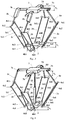
- Fig. 1 there is a basic embodiment of the redundant Delta manipulator depicted, which consists of the platform 2 carried by four parallelograms 3a-3d that are driven using four rotational arms 6a-6d and four rotational drives 7a-7d attached to the frame 1 .
- Each of the parallelograms 3a, 3b, 3c, 3d consists of two parallel arms 5a1 and 5a2 , - 5b1 and 5b2 , - 5c1 and 5c2 , - 5d1 and 5d2 of the same length attached to the rotational arms 6a, 6b, 6c, 6d using the spherical joints 4a1, 4a2, 4a3, 4a4 - 4b1, 4b2, 4b3, 4b4 -4c1, 4c2, 4c3, 4c4 - 4d1, 4d2, 4d3, 4d4 .
- the spherical joints 4 can have two or more degrees of freedom, e.g. if they are created by ball joints, then they have three degrees of freedom, if they are created by Cardan joints, then they have two degrees of freedom, if they are created by pairs of Cardan joints, then they have four degrees of freedom for larger movability, whereas one of the degrees of freedom can be blocked by control.
- the main difference for the embodiment of the Delta manipulator according to the invention when compared to common solutions is the attachment of the spherical joints 4 of the parallelograms 3 to the platform 2 in various planes that are, in Fig. 1 , distant the h 1 non-zero distance.
- the rotational drives 7 are also attached to the frame 1 in various planes that are in Fig. 1 distant the h 2 non-zero distance.
- the same length of the parallelograms 3 and the same length of the rotational arms 6 enable the same power effect of the rotational drives 7 on movement of the platform 2 .
- Determination of a position of the platform in the Cartesian coordinate system of the frame is made by computation from the values of relative movements in the rotational joints 7a-7d with drives, possibly in other joints 4a1-4d4 . Admeasurement of the relative rotational movements in these joints is carried out using sensors installed in the joints.
- Fig. 2 there is another embodiment of the redundant Delta manipulator according to the invention.
- the redundant Delta manipulator consists of the platform 2 carried by four parallelograms 3a-3d , where the parallelograms 3b and 3d are driven using two rotational arms 6b and 6d and two rotational drives 7b and 7d attached to the frame 1 and the parallelograms 3a and 3c using two sliding carts 8a and 8c with two linear actuators 9a and 9c attached to the frame 1 .
- Assembly of the parallelograms 3 and the spherical joints 4 is in conformity with Fig. 1 .
- the rotational drives 7 are also attached to the frame 1 in various planes that are, in Fig. 1 , distant the h 2 non-zero distance.
- Determination of a position of the platform in the Cartesian coordinate system of the frame is made, also for this embodiment, by computation from the values of relative movements in the rotational joints 7b , 7d with drives and in the sliding guides of the carts 8a and 8c with drives, possibly in other joints 4a1 - 4d4 . Admeasurement of the relative rotational and linear movements in these joints is carried out using sensors installed in these joints.
- Fig. 3 there is another variant of the embodiment of the redundant Delta manipulator to the embodiment in Fig. 2 according to the invention.
- the redundant Delta manipulator has the drives created by the rotational arms 6a and 6d positioned side by side, contrary to the embodiment in Fig. 2 , where the drives created by the rotational arms 6b and 6d are positioned against each other.
- the drives created using two sliding carts 8b and 8c and two linear drives 9b and 9c are also positioned side by side, contrary to the embodiment in Fig. 2 , where the drives created with two sliding carts 8a and 8c and two sliding drives 9a and 9c are positioned against each other.
- Fig. 4 there is a schematic depiction of a solution of admeasurement of the movement and the position of the Delta manipulator according to the invention.
- the subject matter is that beside the parallelograms 3 on the rotational arms 6 and/or the sliding carts 8 , which transfer forces from the drives 7 and//or 9 to the platform 2 , a collateral (parallel) structure of the Delta manipulator, which contains only sensors, is positioned. Since the collateral (parallel) structure is only stressed minimally by forces, the admeasurement in the sensors positioned on it is more precise than common admeasurement only in the drives. This leads to a more precise positioning of the Delta manipulator and to the possibility of increasing its rigidity using the feedback control.
- Fig. 4 there is a schematic depiction of a solution of admeasurement of the movement and the position of the Delta manipulator according to the invention.
- the subject matter is that beside the parallelograms 3 on the rotational arms 6 and/or the sliding carts 8 , which transfer forces from
- the Delta manipulator according to the invention in the embodiment in Fig. 1 is depicted.
- arm 10 of the collateral (parallel) construction is attached to the frame 1 using the rotational (spherical with two degrees of freedom - Hook) joint 11 of the collateral construction and attached to the platform 2 using the sliding guide 12 and using the rotational (spherical with three degrees of freedom) joint 11 of the collateral construction.
- the sensors are positioned in the rotational joints 11 and the sliding guides 12 of the collateral construction and their number is six that is more than three degrees of freedom of the platform 2 .
- the procedure of possible control of the Delta manipulator with admeasurement on the collateral construction is as follows:
- the drives 7 and/or 9 of the manipulator are equipped with sensors of relative movement and the sensors are used for stabilization of the drives using a velocity feedback.
- the determination of a position of the platform 2 obtained by the measurement on the collateral construction is used for the position feedback.
- the measurements in the rotational joints 11 and /or in the sliding guides 12 provide more precise data about the position of the platform 2 and its using during control ensures more precise positioning of the platform 2 .
- Fig. 5 there is a schematic depiction of a solution of admeasurement of the movement and the position of the platform of the Delta manipulator according to the invention. It is a schematic plane projection of the Delta manipulator. Beside the parallelograms 3 on the rotational arms 6 and/or the sliding carts 8 , which transfer the forces from the drives 7 and//or 9 to the platform 2, a collateral (parallel) structure of the Delta manipulator, which contains only sensors, is passed from the frame 1 . Since this collateral (parallel) structure is only stressed minimally by forces, the admeasurement in the sensors of the rotation and/or the linear motion positioned on it is more precise than the common admeasurement only in the drives.
- the collateral (parallel) structure of the Delta manipulator is created by two strings of arms consisting of the arms 10a and 10b connected with the rotational (spherical with two degrees of freedom - Hook) joint 11b .
- the rotating arm 10a is attached to the frame 1 using the rotational joint 11a .
- the arm 10b is attached to the platform 2 using the rotational (or spherical) joint 11c .
- the arm 10b can be realized as a parallelogram in a similar way as the parallelogram 3 .
- the sensors of rotation are positioned in the joints 11a, 11b and 11c . Their number can be different.
- the rotational sensors in the joints 11a and 11c are created by 4 sensors for 3 degrees of freedom of the platform 2 .
- the rotational sensors in all the joints 11a, 11b, 11c are created with 8 sensors for 3 degrees of freedom of the platform 2 .
- a redundant number of the sensors is used, so the number of the sensors is higher than the number of degrees of freedom of the manipulator, for improving the accuracy of the measurement, for calibration of the manipulator, for auto-calibration of the collateral construction with the sensors or for on-line measurement and the compensation of temperature deformations.
- the described embodiments of the manipulator are symmetric, but there are more possible variants even with a non-symmetric embodiment.
- the increase of the moment acting from the drives to the platform 2 and of rigidity of the platform 2 of the device according to the invention can be, advantageously, used even for the non-redundant versions of the Delta manipulator with only three parallelograms and three drives.
- the number of the arms with the rotational drive and the number of the arms with the linear drive can be variable and combined.
- all the drives can be rotational or linear or their combination is possible.
- the number of the drives can be larger than four, in the above mentioned embodiments there are always only 4 parallelograms driven by 4 drives.
- the described embodiments of the Delta manipulator use a redundant number of the drives, thus more drives than degrees of freedom of the manipulator. This enables increasing and equalizing the action of forces of the drives on the platform 2 in the entire working area and/or enables the use of other advanced solutions of control with the help of redundant drives, e.g. an antibacklash control.
- the described embodiments of the measurements on the Delta manipulator use a redundant number of sensors, therefore more sensors than degrees of freedom, as well.
- the use of a redundant number of the sensors, so a larger number of the sensors than the number of degrees of freedom of the manipulator, is advantageous for improving measurement accuracy, for the calibration of the manipulator, for auto-calibration of the collateral construction with the sensors or for on-line measurement and compensation of temperature deformations. It is especially advantageous, when the number of the sensors is higher at least by two than the number of degrees of freedom.
- the Delta manipulators can be used, besides for manipulation, also for manufacturing operations and/or for measurements so that a relevant tool (e.g. a spindle with a cutter, a welding head or a measuring probe) is carried by the platform 2.
- a relevant tool e.g. a spindle with a cutter, a welding head or a measuring probe
- Control of the movement of the manipulator is processed by a computer.
Landscapes
- Engineering & Computer Science (AREA)
- Robotics (AREA)
- Mechanical Engineering (AREA)
- Manipulator (AREA)
Description
- The invention concerns a redundant Delta manipulator with a platform connected to a frame using parallelograms and arms connected to them, whereas the parallelograms are connected to the platform or to the frame using spherical joints and the arms are rotationally connected to the frame or to the platform using rotational joints.
- In industrial production, it is still required to speed up the manipulation of objects. Beside common industrial robots and manipulators with a serial kinematic structure, the Delta manipulator with a parallel kinematic structure (
US4976582 ) was designed. It has three rotational or linear drives controlling three parallelograms on which the platform is hung and it performs a linear movement with a manipulated object in three Cartesian coordinate axes x, y ,z. In addition, a fourth drive for the rotation of the platform with a manipulated object around the axis perpendicular to the plane of attachment to the frame has been added, which is realized either by rotation of the whole attachment system of the drives to the frame or by a rope torsion drive from the frame to the platform. The Delta manipulator has the same number of drives as degrees of freedom (three or four). - A Quattro Delta manipulator (
EP 1870214 A1 ) has been designed, which has four rotational drives on the frame controlling four parallelograms carrying the platform. The platform is not rigid, but movable and its rotation is controlled by the fourth added parallelogram. The Quattro Delta manipulator has the same number of drives as degrees of freedom (four). - A redundantly driven version of the Delta manipulator has been designed (Corbel, D. et al.: Towards 100G with PKM. Is actuation redundancy a good solution for pick-and-place?, In: Proc. of 2010 IEEE International Conference on Robotics and Automation, Anchorage Convention District, May 3-8, 2010, Anchorage, Alaska, USA, pp. 4675-4682). This manipulator has four rotational drives on the frame that control four parallelograms carrying the platform that only performs a linear movement with a manipulated object in three Cartesian coordinate axes x ,y, z. Possible rotation is ensured by the rope torsion drive from the frame to the platform. The manipulator is redundantly driven and has a larger number of drives (four) than degrees of freedom (three). A problem can be in the size of the working area due to collisions of the four parallelograms contrary to the original Delta manipulator variant with three parallelograms.
- A problem of all Delta type manipulators is the fact that the platform has a low bending rigidity towards the axis of rotation positioned in the plane of the platform and that admeasurement is carried out by the arms that are deformed by the forces that realize the movement of the platform. A problem of the mentioned Delta type manipulators with four parallelograms is an increased danger of collisions of the parallelograms.
- The aim of the invention is to improve the mechanical properties of rigidity of the platform of the Delta manipulator, to decrease the danger of collisions of their parallelograms and, moreover, to improve the preciseness of admeasurement of the position of the manipulator platform.
- Accordingly, the present invention provides a redundant Delta manipulator as defined in
claim 1.
Preferred embodiments of the invention are defined in the dependent claims. - The advantage of the redundant Delta manipulator device is the increased bending rigidity of the manipulator platform. Another advantage is in a lower danger of collisions of the parallelograms. Another advantage is measurement on the unloaded mechanical construction and thus determination of the position of the manipulator platform is more precise.
- In the enclosed figures there are schematic depictions of the redundant Delta manipulator according to the invention, where
InFigs. 1 to 4 individual alternatives are schematically depicted and
InFig. 5 there is another embodiment of the manipulator supplemented with a measuring parallel structure - In
Fig. 1 there is a basic embodiment of the redundant Delta manipulator depicted, which consists of theplatform 2 carried by fourparallelograms 3a-3d that are driven using fourrotational arms 6a-6d and fourrotational drives 7a-7d attached to theframe 1. Each of theparallelograms rotational arms - The
spherical joints 4 can have two or more degrees of freedom, e.g. if they are created by ball joints, then they have three degrees of freedom, if they are created by Cardan joints, then they have two degrees of freedom, if they are created by pairs of Cardan joints, then they have four degrees of freedom for larger movability, whereas one of the degrees of freedom can be blocked by control. The main difference for the embodiment of the Delta manipulator according to the invention when compared to common solutions is the attachment of thespherical joints 4 of theparallelograms 3 to theplatform 2 in various planes that are, inFig. 1 , distant the h1 non-zero distance. This enables the increase of the moment by which theparallelograms 3 can act on theplatform 2, which results in the increase of rigidity and dynamics of the device. Not to deteriorate manipulability, therotational drives 7 are also attached to theframe 1 in various planes that are inFig. 1 distant the h2 non-zero distance. The optimum choice is when h1=h2 and theparallelograms 3 are of the same length and therotational arms 6 are of the same length, but there can be more variants starting at the h2=0 variant. Attachment of the parallelograms in various planes reduces the danger of their collision during movement, too. The same length of theparallelograms 3 and the same length of therotational arms 6 enable the same power effect of therotational drives 7 on movement of theplatform 2. - Determination of a position of the platform in the Cartesian coordinate system of the frame is made by computation from the values of relative movements in the
rotational joints 7a-7d with drives, possibly in other joints 4a1-4d4. Admeasurement of the relative rotational movements in these joints is carried out using sensors installed in the joints. - In
Fig. 2 there is another embodiment of the redundant Delta manipulator according to the invention. The redundant Delta manipulator consists of theplatform 2 carried by fourparallelograms 3a-3d, where theparallelograms rotational arms rotational drives frame 1 and theparallelograms carts linear actuators frame 1. Assembly of theparallelograms 3 and thespherical joints 4 is in conformity withFig. 1 . The main difference in the embodiment of the Delta manipulator according to the invention, when compared to common solutions, is the attachment of thespherical joints 4 of theparallelograms 3 to theplatform 2 in various planes, which are, inFig. 2 , distant the h1 non-zero distance, as well. This enables the increase of the moment by which theparallelograms 3 can act on theplatform 2, which results in the increase of rigidity and dynamics of the device. - Not to deteriorate manipulability, the
rotational drives 7 are also attached to theframe 1 in various planes that are, inFig. 1 , distant the h2 non-zero distance. The optimum choice for this case is h2=0, since the spherical joints 4b3, 4b4 of theparallelogram 3b and the spherical joints 4d3, 4d4 of theparallelogram 3d are positioned inFig. 2 in the same plane and theparallelograms 3 are of the same length and therotational arms 6 are of the same length, but there can be more variants. - Determination of a position of the platform in the Cartesian coordinate system of the frame is made, also for this embodiment, by computation from the values of relative movements in the
rotational joints carts - In
Fig. 3 there is another variant of the embodiment of the redundant Delta manipulator to the embodiment inFig. 2 according to the invention. In this case, the redundant Delta manipulator has the drives created by therotational arms Fig. 2 , where the drives created by therotational arms carts linear drives Fig. 2 , where the drives created with two slidingcarts drives parallelograms 3 are of the same length and therotational arms 6 are of the same length, but there can be more variants starting at the h2=0 variant. Other parts of the embodiment are the same as inFig. 2 . - In
Fig. 4 there is a schematic depiction of a solution of admeasurement of the movement and the position of the Delta manipulator according to the invention. The subject matter is that beside theparallelograms 3 on therotational arms 6 and/or the sliding carts 8, which transfer forces from thedrives 7 and//or 9 to theplatform 2, a collateral (parallel) structure of the Delta manipulator, which contains only sensors, is positioned. Since the collateral (parallel) structure is only stressed minimally by forces, the admeasurement in the sensors positioned on it is more precise than common admeasurement only in the drives. This leads to a more precise positioning of the Delta manipulator and to the possibility of increasing its rigidity using the feedback control. InFig. 4 the Delta manipulator according to the invention in the embodiment inFig. 1 is depicted. In the embodiment depicted inFig. 4 , between theframe 1 andplatform 2arm 10 of the collateral (parallel) construction is attached to theframe 1 using the rotational (spherical with two degrees of freedom - Hook)joint 11 of the collateral construction and attached to theplatform 2 using thesliding guide 12 and using the rotational (spherical with three degrees of freedom)joint 11 of the collateral construction. The sensors are positioned in therotational joints 11 and thesliding guides 12 of the collateral construction and their number is six that is more than three degrees of freedom of theplatform 2. - The procedure of possible control of the Delta manipulator with admeasurement on the collateral construction is as follows: The
drives 7 and/or 9 of the manipulator are equipped with sensors of relative movement and the sensors are used for stabilization of the drives using a velocity feedback. The determination of a position of theplatform 2 obtained by the measurement on the collateral construction is used for the position feedback. With regard to the fact that thearms 10 of the collateral construction are not stressed by forces of the drives and, therefore, they are not deformed by the forces, the measurements in therotational joints 11 and /or in the slidingguides 12 provide more precise data about the position of theplatform 2 and its using during control ensures more precise positioning of theplatform 2. - In
Fig. 5 there is a schematic depiction of a solution of admeasurement of the movement and the position of the platform of the Delta manipulator according to the invention. It is a schematic plane projection of the Delta manipulator. Beside theparallelograms 3 on therotational arms 6 and/or the sliding carts 8, which transfer the forces from thedrives 7 and//or 9 to theplatform 2, a collateral (parallel) structure of the Delta manipulator, which contains only sensors, is passed from theframe 1. Since this collateral (parallel) structure is only stressed minimally by forces, the admeasurement in the sensors of the rotation and/or the linear motion positioned on it is more precise than the common admeasurement only in the drives. This leads to more precise positioning of theplatform 2 of the Delta manipulator and to the possibility to increase its rigidity using the feedback control. The collateral (parallel) structure of the Delta manipulator is created by two strings of arms consisting of thearms rotating arm 10a is attached to theframe 1 using the rotational joint 11a. Thearm 10b is attached to theplatform 2 using the rotational (or spherical) joint 11c. Thearm 10b can be realized as a parallelogram in a similar way as theparallelogram 3. The sensors of rotation are positioned in thejoints joints platform 2. The rotational sensors in all thejoints platform 2. Advantageously, a redundant number of the sensors is used, so the number of the sensors is higher than the number of degrees of freedom of the manipulator, for improving the accuracy of the measurement, for calibration of the manipulator, for auto-calibration of the collateral construction with the sensors or for on-line measurement and the compensation of temperature deformations. - There are other possible embodiments created by combining the above mentioned variants.. The parallelograms mentioned within the embodiments described above can be replaced with an arm connected to the consequent parts of the manipulator on both ends with the Cardan joint.
- The described embodiments of the manipulator are symmetric, but there are more possible variants even with a non-symmetric embodiment.
- The increase of the moment acting from the drives to the
platform 2 and of rigidity of theplatform 2 of the device according to the invention can be, advantageously, used even for the non-redundant versions of the Delta manipulator with only three parallelograms and three drives.
The number of the arms with the rotational drive and the number of the arms with the linear drive can be variable and combined. For example, all the drives can be rotational or linear or their combination is possible.
The number of the drives can be larger than four, in the above mentioned embodiments there are always only 4 parallelograms driven by 4 drives. - The described embodiments of the Delta manipulator use a redundant number of the drives, thus more drives than degrees of freedom of the manipulator. This enables increasing and equalizing the action of forces of the drives on the
platform 2 in the entire working area and/or enables the use of other advanced solutions of control with the help of redundant drives, e.g. an antibacklash control. - The described embodiments of the measurements on the Delta manipulator use a redundant number of sensors, therefore more sensors than degrees of freedom, as well. The use of a redundant number of the sensors, so a larger number of the sensors than the number of degrees of freedom of the manipulator, is advantageous for improving measurement accuracy, for the calibration of the manipulator, for auto-calibration of the collateral construction with the sensors or for on-line measurement and compensation of temperature deformations. It is especially advantageous, when the number of the sensors is higher at least by two than the number of degrees of freedom.
- The described admeasurement of the movement and the position of the
platform 2 for the Delta manipulators on the collateral (parallel) structure that is not loaded with forces from the drives can be advantageously used for all the variants of Delta manipulators. - The Delta manipulators can be used, besides for manipulation, also for manufacturing operations and/or for measurements so that a relevant tool (e.g. a spindle with a cutter, a welding head or a measuring probe) is carried by the
platform 2. - All the embodiments mentioned above can be further combined arbitrarily. Control of the movement of the manipulator is processed by a computer.
Claims (9)
- Redundant Delta manipulator with a rigid non-configurable platform (2) connected to a frame (1) using parallelograms (3) and arms (6) connected to them, wherein the parallelograms are connected to the platform using spherical joints (4) and the arms are rotationally connected to the frame using rotational joints (7) wherein the spherical joints (4) for connection of adjacent parallelograms (3) to the platform (2) are positioned in different parallel planes, and wherein the axis of the rotational joints (7) for connection of the arms (6) to the frame (1) are positioned in the same plane or in different parallel planes.
- The redundant Delta manipulator, according to Claim 1, comprising two pairs of opposite parallelograms connected to opposite arms, wherein the spherical joints (4) for connecting the opposite parallelograms (3) to the platform (2) are positioned in the same plane parallel to the plane or planes created with other spherical joints (4) for connection of other parallelograms to the platform (2) and wherein the rotational joints (7) for connection the opposite arms (6) to the frame (1) are positioned in the same plane.
- The redundant Delta manipulator, according to claim 1, wherein the parallel planes of the spherical joints (4) are distant from each other in the same value as the parallel planes of the rotational joints (7).
- The redundant Delta manipulator, according to one of the abovementioned Claims, wherein at least one of the arms comprises a sliding cart (8).
- The redundant Delta manipulator, according to one of the abovementioned Claims, comprising two pairs of opposite parallelograms connected to opposite arms, wherein one of the pairs of opposite arms comprises sliding carts (8) and the other pair of opposite arms does not comprise a sliding guide and wherein their rotational joints (7) are positioned in a plane parallel to the plane of the spherical joints (4) for connection of these parallelograms (3b, 3d) to the platform 2.
- The redundant Delta manipulator, according to claims 1 to 4, comprising two pairs of opposite parallelograms connected to opposite arms, wherein one of the pairs of adjacent arms comprises sliding carts (8) and the other pair of adjacent arms does not comprise a sliding guide and wherein their rotational joints (7) are positioned in parallel planes distant from each other in the same value as the parallel planes created by their spherical joints (4) for connection of these parallelograms (3a, 3d) to the platform 2.
- The redundant Delta manipulator, according to one of the abovementioned Claims, featured by the fact that the number of the parallelograms (3) is equal to or larger than four.
- The redundant Delta manipulator, according to one of the abovementioned Claims, featured by the fact that the parallelogram is created by two Cardan joints.
- The redundant Delta manipulator, according to one of the abovementioned Claims, featured by the fact that collateral to the parallelograms (3) there is a collateral measuring, not-loaded construction between the frame (1) and the platform (2).
Applications Claiming Priority (1)
| Application Number | Priority Date | Filing Date | Title |
|---|---|---|---|
| CZ2012-799A CZ2012799A3 (en) | 2012-11-16 | 2012-11-16 | Redundant manipulator |
Publications (2)
| Publication Number | Publication Date |
|---|---|
| EP2732928A1 EP2732928A1 (en) | 2014-05-21 |
| EP2732928B1 true EP2732928B1 (en) | 2018-04-04 |
Family
ID=49585345
Family Applications (1)
| Application Number | Title | Priority Date | Filing Date |
|---|---|---|---|
| EP13466027.3A Not-in-force EP2732928B1 (en) | 2012-11-16 | 2013-11-06 | Redundant Delta manipulator |
Country Status (2)
| Country | Link |
|---|---|
| EP (1) | EP2732928B1 (en) |
| CZ (1) | CZ2012799A3 (en) |
Families Citing this family (5)
| Publication number | Priority date | Publication date | Assignee | Title |
|---|---|---|---|---|
| CN105127998A (en) * | 2015-09-08 | 2015-12-09 | 常州大学 | Three-horizontal movement one-rotation parallel robot platform |
| CN105127983A (en) * | 2015-10-09 | 2015-12-09 | 常州大学 | Three-translation and one-rotation parallel mechanism manipulator |
| CN106429195A (en) * | 2016-12-27 | 2017-02-22 | 南宁学院 | Correcting device for sliding parallel conveyor belt |
| RU179567U1 (en) * | 2017-12-06 | 2018-05-17 | Федеральное государственное бюджетное учреждение науки Институт машиноведения им. А.А. Благонравова Российской академии наук (ИМАШ РАН) | SPATIAL MECHANISM WITH A CIRCULAR GUIDE |
| CN116141293B (en) * | 2023-04-07 | 2025-07-22 | 上海工程技术大学 | Movable parallel mechanism with symmetrical multiple control modes |
Family Cites Families (7)
| Publication number | Priority date | Publication date | Assignee | Title |
|---|---|---|---|---|
| CH672089A5 (en) | 1985-12-16 | 1989-10-31 | Sogeva Sa | |
| CN1326671C (en) * | 2003-07-16 | 2007-07-18 | 刘辛军 | Linkage branch mechanism of parallel robot and six freedom parallel robot mechanism |
| ES2258917B1 (en) * | 2005-02-17 | 2007-12-01 | Fundacion Fatronik | PARALLEL ROBOT WITH FOUR DEGREES OF HIGH SPEED FREEDOM. |
| CN100393484C (en) * | 2006-06-09 | 2008-06-11 | 北京工业大学 | Three-translation-rotation parallel mechanism |
| CN101863024B (en) * | 2010-06-29 | 2011-11-09 | 天津大学 | Three-dimensional translation and one-dimensional rotation parallel mechanism capable of realizing high-speed movement |
| CN102441889A (en) * | 2010-09-30 | 2012-05-09 | 鸿富锦精密工业(深圳)有限公司 | Parallel-connection robot |
| CA2734318C (en) * | 2011-03-17 | 2017-08-08 | Crosswing Inc. | Delta robot with omni treaded wheelbase |
-
2012
- 2012-11-16 CZ CZ2012-799A patent/CZ2012799A3/en not_active IP Right Cessation
-
2013
- 2013-11-06 EP EP13466027.3A patent/EP2732928B1/en not_active Not-in-force
Non-Patent Citations (1)
| Title |
|---|
| None * |
Also Published As
| Publication number | Publication date |
|---|---|
| CZ304674B6 (en) | 2014-08-27 |
| CZ2012799A3 (en) | 2014-08-27 |
| EP2732928A1 (en) | 2014-05-21 |
Similar Documents
| Publication | Publication Date | Title |
|---|---|---|
| CN109196429B (en) | Method, restraint, and system for determining geometric properties of a manipulator | |
| Xiong et al. | Stiffness-based pose optimization of an industrial robot for five-axis milling | |
| US8977392B2 (en) | Robot control device, robot control method, robot control program, and robot system | |
| JP5282874B2 (en) | Manipulator system | |
| CN114829078B (en) | Coordinate positioning arm | |
| JP6151159B2 (en) | Cooperative transfer robot system | |
| US8099188B2 (en) | Parallel kinematic robot and method for controlling this robot | |
| EP2732928A1 (en) | Redundant Delta manipulator | |
| Zhao et al. | Vibration error-based trajectory planning of a 5-dof hybrid machine tool | |
| JP6602620B2 (en) | Combined link actuator | |
| KR20110083341A (en) | Manipulator and its control method | |
| US12103164B2 (en) | Gripper mechanism | |
| KR20130056344A (en) | Control method for seven-shaft multi-joint robot, control program, and robot control device | |
| KR20180099623A (en) | Robot arm and robot wrist | |
| JP2016002627A (en) | Working trajectory generation apparatus and method | |
| JP6390832B2 (en) | Processing trajectory generating apparatus and method | |
| JP4289506B2 (en) | 4-DOF parallel robot | |
| CN102431027A (en) | A three-degree-of-freedom parallel robot mechanism with completely decoupled motion | |
| Yang et al. | CurviPicker: a continuum robot for pick-and-place tasks | |
| KR102814770B1 (en) | Manipulator for finishng operation and operating method of the same | |
| CN115139299B (en) | A method for maintaining the posture of end tool | |
| Ángel et al. | RoboTenis: design, dynamic modeling and preliminary control | |
| KR20230133015A (en) | Apparatus and method for compensating for deflection of a manipulator using an tilt sensor | |
| JP2023095023A (en) | Robots, manufacturing methods and distributed sensors | |
| Li et al. | A dual-robot system design for in-cabin pose adjusting of heavy parts |
Legal Events
| Date | Code | Title | Description |
|---|---|---|---|
| PUAI | Public reference made under article 153(3) epc to a published international application that has entered the european phase |
Free format text: ORIGINAL CODE: 0009012 |
|
| 17P | Request for examination filed |
Effective date: 20131106 |
|
| AK | Designated contracting states |
Kind code of ref document: A1 Designated state(s): AL AT BE BG CH CY CZ DE DK EE ES FI FR GB GR HR HU IE IS IT LI LT LU LV MC MK MT NL NO PL PT RO RS SE SI SK SM TR |
|
| AX | Request for extension of the european patent |
Extension state: BA ME |
|
| RBV | Designated contracting states (corrected) |
Designated state(s): AL AT BE BG CH CY CZ DE DK EE ES FI FR GB GR HR HU IE IS IT LI LT LU LV MC MK MT NL NO PL PT RO RS SE SI SK SM TR |
|
| R17P | Request for examination filed (corrected) |
Effective date: 20150311 |
|
| GRAP | Despatch of communication of intention to grant a patent |
Free format text: ORIGINAL CODE: EPIDOSNIGR1 |
|
| INTG | Intention to grant announced |
Effective date: 20170914 |
|
| GRAS | Grant fee paid |
Free format text: ORIGINAL CODE: EPIDOSNIGR3 |
|
| GRAJ | Information related to disapproval of communication of intention to grant by the applicant or resumption of examination proceedings by the epo deleted |
Free format text: ORIGINAL CODE: EPIDOSDIGR1 |
|
| GRAL | Information related to payment of fee for publishing/printing deleted |
Free format text: ORIGINAL CODE: EPIDOSDIGR3 |
|
| GRAP | Despatch of communication of intention to grant a patent |
Free format text: ORIGINAL CODE: EPIDOSNIGR1 |
|
| INTC | Intention to grant announced (deleted) | ||
| INTG | Intention to grant announced |
Effective date: 20180202 |
|
| GRAA | (expected) grant |
Free format text: ORIGINAL CODE: 0009210 |
|
| AK | Designated contracting states |
Kind code of ref document: B1 Designated state(s): AL AT BE BG CH CY CZ DE DK EE ES FI FR GB GR HR HU IE IS IT LI LT LU LV MC MK MT NL NO PL PT RO RS SE SI SK SM TR |
|
| REG | Reference to a national code |
Ref country code: GB Ref legal event code: FG4D |
|
| REG | Reference to a national code |
Ref country code: CH Ref legal event code: EP |
|
| REG | Reference to a national code |
Ref country code: AT Ref legal event code: REF Ref document number: 985104 Country of ref document: AT Kind code of ref document: T Effective date: 20180415 |
|
| REG | Reference to a national code |
Ref country code: IE Ref legal event code: FG4D |
|
| REG | Reference to a national code |
Ref country code: DE Ref legal event code: R096 Ref document number: 602013035338 Country of ref document: DE |
|
| REG | Reference to a national code |
Ref country code: NL Ref legal event code: MP Effective date: 20180404 |
|
| REG | Reference to a national code |
Ref country code: LT Ref legal event code: MG4D |
|
| PG25 | Lapsed in a contracting state [announced via postgrant information from national office to epo] |
Ref country code: NL Free format text: LAPSE BECAUSE OF FAILURE TO SUBMIT A TRANSLATION OF THE DESCRIPTION OR TO PAY THE FEE WITHIN THE PRESCRIBED TIME-LIMIT Effective date: 20180404 |
|
| PG25 | Lapsed in a contracting state [announced via postgrant information from national office to epo] |
Ref country code: PL Free format text: LAPSE BECAUSE OF FAILURE TO SUBMIT A TRANSLATION OF THE DESCRIPTION OR TO PAY THE FEE WITHIN THE PRESCRIBED TIME-LIMIT Effective date: 20180404 Ref country code: AL Free format text: LAPSE BECAUSE OF FAILURE TO SUBMIT A TRANSLATION OF THE DESCRIPTION OR TO PAY THE FEE WITHIN THE PRESCRIBED TIME-LIMIT Effective date: 20180404 Ref country code: FI Free format text: LAPSE BECAUSE OF FAILURE TO SUBMIT A TRANSLATION OF THE DESCRIPTION OR TO PAY THE FEE WITHIN THE PRESCRIBED TIME-LIMIT Effective date: 20180404 Ref country code: NO Free format text: LAPSE BECAUSE OF FAILURE TO SUBMIT A TRANSLATION OF THE DESCRIPTION OR TO PAY THE FEE WITHIN THE PRESCRIBED TIME-LIMIT Effective date: 20180704 Ref country code: SE Free format text: LAPSE BECAUSE OF FAILURE TO SUBMIT A TRANSLATION OF THE DESCRIPTION OR TO PAY THE FEE WITHIN THE PRESCRIBED TIME-LIMIT Effective date: 20180404 Ref country code: BG Free format text: LAPSE BECAUSE OF FAILURE TO SUBMIT A TRANSLATION OF THE DESCRIPTION OR TO PAY THE FEE WITHIN THE PRESCRIBED TIME-LIMIT Effective date: 20180704 Ref country code: ES Free format text: LAPSE BECAUSE OF FAILURE TO SUBMIT A TRANSLATION OF THE DESCRIPTION OR TO PAY THE FEE WITHIN THE PRESCRIBED TIME-LIMIT Effective date: 20180404 Ref country code: LT Free format text: LAPSE BECAUSE OF FAILURE TO SUBMIT A TRANSLATION OF THE DESCRIPTION OR TO PAY THE FEE WITHIN THE PRESCRIBED TIME-LIMIT Effective date: 20180404 |
|
| PG25 | Lapsed in a contracting state [announced via postgrant information from national office to epo] |
Ref country code: RS Free format text: LAPSE BECAUSE OF FAILURE TO SUBMIT A TRANSLATION OF THE DESCRIPTION OR TO PAY THE FEE WITHIN THE PRESCRIBED TIME-LIMIT Effective date: 20180404 Ref country code: HR Free format text: LAPSE BECAUSE OF FAILURE TO SUBMIT A TRANSLATION OF THE DESCRIPTION OR TO PAY THE FEE WITHIN THE PRESCRIBED TIME-LIMIT Effective date: 20180404 Ref country code: GR Free format text: LAPSE BECAUSE OF FAILURE TO SUBMIT A TRANSLATION OF THE DESCRIPTION OR TO PAY THE FEE WITHIN THE PRESCRIBED TIME-LIMIT Effective date: 20180705 Ref country code: LV Free format text: LAPSE BECAUSE OF FAILURE TO SUBMIT A TRANSLATION OF THE DESCRIPTION OR TO PAY THE FEE WITHIN THE PRESCRIBED TIME-LIMIT Effective date: 20180404 |
|
| REG | Reference to a national code |
Ref country code: AT Ref legal event code: MK05 Ref document number: 985104 Country of ref document: AT Kind code of ref document: T Effective date: 20180404 |
|
| PG25 | Lapsed in a contracting state [announced via postgrant information from national office to epo] |
Ref country code: PT Free format text: LAPSE BECAUSE OF FAILURE TO SUBMIT A TRANSLATION OF THE DESCRIPTION OR TO PAY THE FEE WITHIN THE PRESCRIBED TIME-LIMIT Effective date: 20180806 |
|
| REG | Reference to a national code |
Ref country code: DE Ref legal event code: R097 Ref document number: 602013035338 Country of ref document: DE |
|
| PG25 | Lapsed in a contracting state [announced via postgrant information from national office to epo] |
Ref country code: CZ Free format text: LAPSE BECAUSE OF FAILURE TO SUBMIT A TRANSLATION OF THE DESCRIPTION OR TO PAY THE FEE WITHIN THE PRESCRIBED TIME-LIMIT Effective date: 20180404 Ref country code: DK Free format text: LAPSE BECAUSE OF FAILURE TO SUBMIT A TRANSLATION OF THE DESCRIPTION OR TO PAY THE FEE WITHIN THE PRESCRIBED TIME-LIMIT Effective date: 20180404 Ref country code: EE Free format text: LAPSE BECAUSE OF FAILURE TO SUBMIT A TRANSLATION OF THE DESCRIPTION OR TO PAY THE FEE WITHIN THE PRESCRIBED TIME-LIMIT Effective date: 20180404 Ref country code: AT Free format text: LAPSE BECAUSE OF FAILURE TO SUBMIT A TRANSLATION OF THE DESCRIPTION OR TO PAY THE FEE WITHIN THE PRESCRIBED TIME-LIMIT Effective date: 20180404 Ref country code: SK Free format text: LAPSE BECAUSE OF FAILURE TO SUBMIT A TRANSLATION OF THE DESCRIPTION OR TO PAY THE FEE WITHIN THE PRESCRIBED TIME-LIMIT Effective date: 20180404 Ref country code: RO Free format text: LAPSE BECAUSE OF FAILURE TO SUBMIT A TRANSLATION OF THE DESCRIPTION OR TO PAY THE FEE WITHIN THE PRESCRIBED TIME-LIMIT Effective date: 20180404 |
|
| PLBE | No opposition filed within time limit |
Free format text: ORIGINAL CODE: 0009261 |
|
| STAA | Information on the status of an ep patent application or granted ep patent |
Free format text: STATUS: NO OPPOSITION FILED WITHIN TIME LIMIT |
|
| PG25 | Lapsed in a contracting state [announced via postgrant information from national office to epo] |
Ref country code: IT Free format text: LAPSE BECAUSE OF FAILURE TO SUBMIT A TRANSLATION OF THE DESCRIPTION OR TO PAY THE FEE WITHIN THE PRESCRIBED TIME-LIMIT Effective date: 20180404 Ref country code: SM Free format text: LAPSE BECAUSE OF FAILURE TO SUBMIT A TRANSLATION OF THE DESCRIPTION OR TO PAY THE FEE WITHIN THE PRESCRIBED TIME-LIMIT Effective date: 20180404 |
|
| 26N | No opposition filed |
Effective date: 20190107 |
|
| PG25 | Lapsed in a contracting state [announced via postgrant information from national office to epo] |
Ref country code: SI Free format text: LAPSE BECAUSE OF FAILURE TO SUBMIT A TRANSLATION OF THE DESCRIPTION OR TO PAY THE FEE WITHIN THE PRESCRIBED TIME-LIMIT Effective date: 20180404 |
|
| REG | Reference to a national code |
Ref country code: CH Ref legal event code: PL |
|
| GBPC | Gb: european patent ceased through non-payment of renewal fee |
Effective date: 20181106 |
|
| PG25 | Lapsed in a contracting state [announced via postgrant information from national office to epo] |
Ref country code: LU Free format text: LAPSE BECAUSE OF NON-PAYMENT OF DUE FEES Effective date: 20181106 Ref country code: MC Free format text: LAPSE BECAUSE OF FAILURE TO SUBMIT A TRANSLATION OF THE DESCRIPTION OR TO PAY THE FEE WITHIN THE PRESCRIBED TIME-LIMIT Effective date: 20180404 |
|
| REG | Reference to a national code |
Ref country code: BE Ref legal event code: MM Effective date: 20181130 |
|
| REG | Reference to a national code |
Ref country code: IE Ref legal event code: MM4A |
|
| PG25 | Lapsed in a contracting state [announced via postgrant information from national office to epo] |
Ref country code: CH Free format text: LAPSE BECAUSE OF NON-PAYMENT OF DUE FEES Effective date: 20181130 Ref country code: LI Free format text: LAPSE BECAUSE OF NON-PAYMENT OF DUE FEES Effective date: 20181130 |
|
| PG25 | Lapsed in a contracting state [announced via postgrant information from national office to epo] |
Ref country code: FR Free format text: LAPSE BECAUSE OF NON-PAYMENT OF DUE FEES Effective date: 20181130 Ref country code: IE Free format text: LAPSE BECAUSE OF NON-PAYMENT OF DUE FEES Effective date: 20181106 |
|
| PG25 | Lapsed in a contracting state [announced via postgrant information from national office to epo] |
Ref country code: BE Free format text: LAPSE BECAUSE OF NON-PAYMENT OF DUE FEES Effective date: 20181130 |
|
| PG25 | Lapsed in a contracting state [announced via postgrant information from national office to epo] |
Ref country code: GB Free format text: LAPSE BECAUSE OF NON-PAYMENT OF DUE FEES Effective date: 20181106 |
|
| PG25 | Lapsed in a contracting state [announced via postgrant information from national office to epo] |
Ref country code: MT Free format text: LAPSE BECAUSE OF NON-PAYMENT OF DUE FEES Effective date: 20181106 |
|
| PG25 | Lapsed in a contracting state [announced via postgrant information from national office to epo] |
Ref country code: TR Free format text: LAPSE BECAUSE OF FAILURE TO SUBMIT A TRANSLATION OF THE DESCRIPTION OR TO PAY THE FEE WITHIN THE PRESCRIBED TIME-LIMIT Effective date: 20180404 |
|
| PG25 | Lapsed in a contracting state [announced via postgrant information from national office to epo] |
Ref country code: CY Free format text: LAPSE BECAUSE OF FAILURE TO SUBMIT A TRANSLATION OF THE DESCRIPTION OR TO PAY THE FEE WITHIN THE PRESCRIBED TIME-LIMIT Effective date: 20180404 Ref country code: MK Free format text: LAPSE BECAUSE OF NON-PAYMENT OF DUE FEES Effective date: 20180404 Ref country code: HU Free format text: LAPSE BECAUSE OF FAILURE TO SUBMIT A TRANSLATION OF THE DESCRIPTION OR TO PAY THE FEE WITHIN THE PRESCRIBED TIME-LIMIT; INVALID AB INITIO Effective date: 20131106 |
|
| PG25 | Lapsed in a contracting state [announced via postgrant information from national office to epo] |
Ref country code: IS Free format text: LAPSE BECAUSE OF FAILURE TO SUBMIT A TRANSLATION OF THE DESCRIPTION OR TO PAY THE FEE WITHIN THE PRESCRIBED TIME-LIMIT Effective date: 20180804 |
|
| PGFP | Annual fee paid to national office [announced via postgrant information from national office to epo] |
Ref country code: DE Payment date: 20231010 Year of fee payment: 11 |
|
| REG | Reference to a national code |
Ref country code: DE Ref legal event code: R119 Ref document number: 602013035338 Country of ref document: DE |
|
| PG25 | Lapsed in a contracting state [announced via postgrant information from national office to epo] |
Ref country code: DE Free format text: LAPSE BECAUSE OF NON-PAYMENT OF DUE FEES Effective date: 20250603 |