EP2732847A1 - Catheter and support cannula assembly - Google Patents
Catheter and support cannula assembly Download PDFInfo
- Publication number
- EP2732847A1 EP2732847A1 EP13192921.8A EP13192921A EP2732847A1 EP 2732847 A1 EP2732847 A1 EP 2732847A1 EP 13192921 A EP13192921 A EP 13192921A EP 2732847 A1 EP2732847 A1 EP 2732847A1
- Authority
- EP
- European Patent Office
- Prior art keywords
- catheter
- tip
- support
- segment
- cannula
- Prior art date
- Legal status (The legal status is an assumption and is not a legal conclusion. Google has not performed a legal analysis and makes no representation as to the accuracy of the status listed.)
- Withdrawn
Links
- 239000012530 fluid Substances 0.000 claims description 40
- 238000000034 method Methods 0.000 claims description 23
- 239000000463 material Substances 0.000 claims description 17
- 238000004891 communication Methods 0.000 claims description 10
- 230000002401 inhibitory effect Effects 0.000 claims 1
- 208000031872 Body Remains Diseases 0.000 abstract 1
- 230000007246 mechanism Effects 0.000 description 10
- 239000002783 friction material Substances 0.000 description 6
- 238000001802 infusion Methods 0.000 description 6
- 239000004677 Nylon Substances 0.000 description 4
- 229940079593 drug Drugs 0.000 description 4
- 239000003814 drug Substances 0.000 description 4
- 229910001000 nickel titanium Inorganic materials 0.000 description 4
- 229920001778 nylon Polymers 0.000 description 4
- 229920001296 polysiloxane Polymers 0.000 description 4
- 229920001343 polytetrafluoroethylene Polymers 0.000 description 4
- 239000004810 polytetrafluoroethylene Substances 0.000 description 4
- 229910001220 stainless steel Inorganic materials 0.000 description 4
- 239000010935 stainless steel Substances 0.000 description 4
- 239000004696 Poly ether ether ketone Substances 0.000 description 3
- 239000007769 metal material Substances 0.000 description 3
- 229920002530 polyetherether ketone Polymers 0.000 description 3
- -1 polytetrafluoroethylene Polymers 0.000 description 3
- 229920002635 polyurethane Polymers 0.000 description 3
- 239000004814 polyurethane Substances 0.000 description 3
- 230000007704 transition Effects 0.000 description 3
- 206010000269 abscess Diseases 0.000 description 2
- 210000003484 anatomy Anatomy 0.000 description 2
- 229920000295 expanded polytetrafluoroethylene Polymers 0.000 description 2
- 230000005484 gravity Effects 0.000 description 2
- 238000003780 insertion Methods 0.000 description 2
- 230000037431 insertion Effects 0.000 description 2
- 210000003734 kidney Anatomy 0.000 description 2
- 239000000314 lubricant Substances 0.000 description 2
- HLXZNVUGXRDIFK-UHFFFAOYSA-N nickel titanium Chemical compound [Ti].[Ti].[Ti].[Ti].[Ti].[Ti].[Ti].[Ti].[Ti].[Ti].[Ti].[Ni].[Ni].[Ni].[Ni].[Ni].[Ni].[Ni].[Ni].[Ni].[Ni].[Ni].[Ni].[Ni].[Ni] HLXZNVUGXRDIFK-UHFFFAOYSA-N 0.000 description 2
- 239000004800 polyvinyl chloride Substances 0.000 description 2
- 239000007787 solid Substances 0.000 description 2
- 238000013519 translation Methods 0.000 description 2
- 206010060921 Abdominal abscess Diseases 0.000 description 1
- 239000004952 Polyamide Substances 0.000 description 1
- 239000004698 Polyethylene Substances 0.000 description 1
- UIIMBOGNXHQVGW-DEQYMQKBSA-M Sodium bicarbonate-14C Chemical compound [Na+].O[14C]([O-])=O UIIMBOGNXHQVGW-DEQYMQKBSA-M 0.000 description 1
- 208000033809 Suppuration Diseases 0.000 description 1
- 238000004026 adhesive bonding Methods 0.000 description 1
- 210000000013 bile duct Anatomy 0.000 description 1
- 210000004204 blood vessel Anatomy 0.000 description 1
- 210000001124 body fluid Anatomy 0.000 description 1
- 239000010839 body fluid Substances 0.000 description 1
- 229940039231 contrast media Drugs 0.000 description 1
- 239000002872 contrast media Substances 0.000 description 1
- 230000008878 coupling Effects 0.000 description 1
- 238000010168 coupling process Methods 0.000 description 1
- 238000005859 coupling reaction Methods 0.000 description 1
- 230000000916 dilatatory effect Effects 0.000 description 1
- 238000005553 drilling Methods 0.000 description 1
- 239000013013 elastic material Substances 0.000 description 1
- 238000001125 extrusion Methods 0.000 description 1
- 238000002513 implantation Methods 0.000 description 1
- 208000014674 injury Diseases 0.000 description 1
- 229910052751 metal Inorganic materials 0.000 description 1
- 239000002184 metal Substances 0.000 description 1
- 239000000203 mixture Substances 0.000 description 1
- 238000000465 moulding Methods 0.000 description 1
- 238000012273 nephrostomy Methods 0.000 description 1
- 239000004033 plastic Substances 0.000 description 1
- 229920003023 plastic Polymers 0.000 description 1
- 229920002647 polyamide Polymers 0.000 description 1
- 229920000573 polyethylene Polymers 0.000 description 1
- 229920000915 polyvinyl chloride Polymers 0.000 description 1
- 230000003014 reinforcing effect Effects 0.000 description 1
- 230000004044 response Effects 0.000 description 1
- 239000012781 shape memory material Substances 0.000 description 1
- 239000007779 soft material Substances 0.000 description 1
- 238000005476 soldering Methods 0.000 description 1
- 238000009987 spinning Methods 0.000 description 1
- 238000005728 strengthening Methods 0.000 description 1
- 230000008733 trauma Effects 0.000 description 1
- 210000000626 ureter Anatomy 0.000 description 1
- 210000002700 urine Anatomy 0.000 description 1
- 238000003466 welding Methods 0.000 description 1
Images




Classifications
-
- A—HUMAN NECESSITIES
- A61—MEDICAL OR VETERINARY SCIENCE; HYGIENE
- A61B—DIAGNOSIS; SURGERY; IDENTIFICATION
- A61B17/00—Surgical instruments, devices or methods
- A61B17/34—Trocars; Puncturing needles
- A61B17/3417—Details of tips or shafts, e.g. grooves, expandable, bendable; Multiple coaxial sliding cannulas, e.g. for dilating
- A61B17/3421—Cannulas
-
- A—HUMAN NECESSITIES
- A61—MEDICAL OR VETERINARY SCIENCE; HYGIENE
- A61M—DEVICES FOR INTRODUCING MEDIA INTO, OR ONTO, THE BODY; DEVICES FOR TRANSDUCING BODY MEDIA OR FOR TAKING MEDIA FROM THE BODY; DEVICES FOR PRODUCING OR ENDING SLEEP OR STUPOR
- A61M25/00—Catheters; Hollow probes
- A61M25/01—Introducing, guiding, advancing, emplacing or holding catheters
- A61M25/0102—Insertion or introduction using an inner stiffening member, e.g. stylet or push-rod
-
- A—HUMAN NECESSITIES
- A61—MEDICAL OR VETERINARY SCIENCE; HYGIENE
- A61B—DIAGNOSIS; SURGERY; IDENTIFICATION
- A61B17/00—Surgical instruments, devices or methods
- A61B17/34—Trocars; Puncturing needles
- A61B17/3415—Trocars; Puncturing needles for introducing tubes or catheters, e.g. gastrostomy tubes, drain catheters
-
- A—HUMAN NECESSITIES
- A61—MEDICAL OR VETERINARY SCIENCE; HYGIENE
- A61M—DEVICES FOR INTRODUCING MEDIA INTO, OR ONTO, THE BODY; DEVICES FOR TRANSDUCING BODY MEDIA OR FOR TAKING MEDIA FROM THE BODY; DEVICES FOR PRODUCING OR ENDING SLEEP OR STUPOR
- A61M25/00—Catheters; Hollow probes
- A61M25/01—Introducing, guiding, advancing, emplacing or holding catheters
- A61M25/06—Body-piercing guide needles or the like
- A61M25/065—Guide needles
-
- A—HUMAN NECESSITIES
- A61—MEDICAL OR VETERINARY SCIENCE; HYGIENE
- A61M—DEVICES FOR INTRODUCING MEDIA INTO, OR ONTO, THE BODY; DEVICES FOR TRANSDUCING BODY MEDIA OR FOR TAKING MEDIA FROM THE BODY; DEVICES FOR PRODUCING OR ENDING SLEEP OR STUPOR
- A61M27/00—Drainage appliance for wounds or the like, i.e. wound drains, implanted drains
-
- A—HUMAN NECESSITIES
- A61—MEDICAL OR VETERINARY SCIENCE; HYGIENE
- A61M—DEVICES FOR INTRODUCING MEDIA INTO, OR ONTO, THE BODY; DEVICES FOR TRANSDUCING BODY MEDIA OR FOR TAKING MEDIA FROM THE BODY; DEVICES FOR PRODUCING OR ENDING SLEEP OR STUPOR
- A61M25/00—Catheters; Hollow probes
- A61M25/01—Introducing, guiding, advancing, emplacing or holding catheters
- A61M25/0105—Steering means as part of the catheter or advancing means; Markers for positioning
- A61M25/0133—Tip steering devices
- A61M2025/0163—Looped catheters
-
- A—HUMAN NECESSITIES
- A61—MEDICAL OR VETERINARY SCIENCE; HYGIENE
- A61M—DEVICES FOR INTRODUCING MEDIA INTO, OR ONTO, THE BODY; DEVICES FOR TRANSDUCING BODY MEDIA OR FOR TAKING MEDIA FROM THE BODY; DEVICES FOR PRODUCING OR ENDING SLEEP OR STUPOR
- A61M25/00—Catheters; Hollow probes
- A61M25/01—Introducing, guiding, advancing, emplacing or holding catheters
- A61M25/06—Body-piercing guide needles or the like
- A61M25/0662—Guide tubes
- A61M2025/0681—Systems with catheter and outer tubing, e.g. sheath, sleeve or guide tube
-
- A—HUMAN NECESSITIES
- A61—MEDICAL OR VETERINARY SCIENCE; HYGIENE
- A61M—DEVICES FOR INTRODUCING MEDIA INTO, OR ONTO, THE BODY; DEVICES FOR TRANSDUCING BODY MEDIA OR FOR TAKING MEDIA FROM THE BODY; DEVICES FOR PRODUCING OR ENDING SLEEP OR STUPOR
- A61M25/00—Catheters; Hollow probes
- A61M25/0067—Catheters; Hollow probes characterised by the distal end, e.g. tips
- A61M25/0068—Static characteristics of the catheter tip, e.g. shape, atraumatic tip, curved tip or tip structure
- A61M25/007—Side holes, e.g. their profiles or arrangements; Provisions to keep side holes unblocked
-
- A—HUMAN NECESSITIES
- A61—MEDICAL OR VETERINARY SCIENCE; HYGIENE
- A61M—DEVICES FOR INTRODUCING MEDIA INTO, OR ONTO, THE BODY; DEVICES FOR TRANSDUCING BODY MEDIA OR FOR TAKING MEDIA FROM THE BODY; DEVICES FOR PRODUCING OR ENDING SLEEP OR STUPOR
- A61M25/00—Catheters; Hollow probes
- A61M25/0067—Catheters; Hollow probes characterised by the distal end, e.g. tips
- A61M25/0074—Dynamic characteristics of the catheter tip, e.g. openable, closable, expandable or deformable
-
- A—HUMAN NECESSITIES
- A61—MEDICAL OR VETERINARY SCIENCE; HYGIENE
- A61M—DEVICES FOR INTRODUCING MEDIA INTO, OR ONTO, THE BODY; DEVICES FOR TRANSDUCING BODY MEDIA OR FOR TAKING MEDIA FROM THE BODY; DEVICES FOR PRODUCING OR ENDING SLEEP OR STUPOR
- A61M25/00—Catheters; Hollow probes
- A61M25/01—Introducing, guiding, advancing, emplacing or holding catheters
- A61M25/02—Holding devices, e.g. on the body
- A61M25/04—Holding devices, e.g. on the body in the body, e.g. expansible
-
- A—HUMAN NECESSITIES
- A61—MEDICAL OR VETERINARY SCIENCE; HYGIENE
- A61M—DEVICES FOR INTRODUCING MEDIA INTO, OR ONTO, THE BODY; DEVICES FOR TRANSDUCING BODY MEDIA OR FOR TAKING MEDIA FROM THE BODY; DEVICES FOR PRODUCING OR ENDING SLEEP OR STUPOR
- A61M29/00—Dilators with or without means for introducing media, e.g. remedies
Definitions
- This disclosure relates generally to medical devices. More specifically, this disclosure relates to drainage/infusion catheters for percutaneous placement within a body cavity to drain a fluid from the body cavity and/or to infuse a fluid into the body cavity.
- One use of the catheter may be to drain excess fluid.
- the catheter may be used to drain urine from the kidney when there is an obstruction in the ureter.
- Another use of the catheter may be to drain fluid from an infected collection.
- the catheter may be used to drain pus from an abdominal abscess.
- the flexible distal portion at the end of the catheter may be altered to help to maintain the flexible distal portion within the body cavity.
- one or more loops may be imparted at the distal flexible end of the catheter. These loops may be much larger than the hole through which the catheter is inserted.
- Excess or infected fluid may enter a port or hole in the tubular member of the catheter and be withdrawn from the body cavity by aspiration or by gravity.
- inserting the drainage catheter into the body cavity is done with the aid of an insertion tool, such as a stiffening cannula.
- the stiffening cannula may be inserted into the drainage catheter to support the drainage catheter and/or to at least partially straighten the loops at the distal flexible end of the catheter for placement in the body cavity.
- the stiffening cannula has a cylindrical shape with an outer diameter that is either larger than the inner diameter of the tip of the drainage catheter (which may be tapered) or smaller than the inner diameter of the body of the drainage catheter.
- a large gauge stiffening cannula may be unable to fit within the tip of the drainage catheter, which may result in a failure to straighten and/or support the tip of the drainage catheter.
- a small gauge stiffening cannula may not fully contact the inner surface of the body of the drainage catheter, which may result in a failure to support the body of the catheter. Failure to support and/or straighten the drainage catheter may result in damage to the drainage catheter caused by buckling and/or puncturing of the drainage catheter during insertion of the drainage catheter into the body cavity.
- the present embodiments provide a drainage/infusion catheter for percutaneous placement within a body cavity to drain a fluid from the body cavity and/or to infuse a fluid into the body cavity.
- a system may include a catheter and an elongate tubular support cannula.
- the catheter may include an elongate tubular member including a proximal end, a distal end, a lumen extending longitudinally within the catheter, a tapered tip positioned at the distal end of the catheter, and a body extending proximally from the tip.
- the tip of the catheter may have an inner diameter that is smaller than an inner diameter of the body of the catheter.
- the support cannula may be slidably received within the lumen of the catheter.
- the support cannula may include a proximal end, a distal end, a lumen extending longitudinally within the support cannula, a tip positioned at the distal end of the support cannula and disposed within the tip of the catheter such that the tip of the support cannula does not extend distally beyond the distal end of the catheter, and a support segment extending proximally from the tip of the support cannula and disposed within the body of the catheter such that the body of the catheter remains in a non-stretched configuration.
- the tip of the support cannula may have an outer diameter corresponding to the inner diameter of the tip of the catheter.
- the support segment may have an outer diameter corresponding to the inner diameter of the body of the catheter.
- the body of the catheter may include a perforated segment including an aperture disposed in the catheter and in fluid communication with the lumen of the catheter.
- the support segment of the support cannula may extend from the tip of the support cannula to at least a position longitudinally adjacent to a proximal end of the perforated segment.
- a system may include a catheter, an elongate tubular support cannula, and an elongate needle.
- the catheter may include an elongate tubular member including a proximal end, a distal end, a catheter lumen extending longitudinally within the catheter, a catheter body, and a catheter tip extending distally from the catheter body.
- the catheter tip may include a tapered outer surface and an inner diameter that is smaller than an inner diameter of the catheter body.
- the support cannula may be slidably received within the catheter lumen and include a proximal end, a distal end, a cannula lumen extending longitudinally within the support cannula, a support segment disposed within the catheter body, and a cannula tip extending distally from the support segment and disposed within the catheter tip.
- the support segment may include an outer diameter that is substantially constant along a length of the support segment and corresponds to the inner diameter of the catheter body.
- the cannula tip may include an outer diameter that is smaller than the outer diameter of the support segment and corresponds to the inner diameter of the catheter tip.
- the needle may be slidably received within the cannula lumen and include a proximal end, a distal end, and a sharpened tip positioned at the distal end of the needle and disposed distal of the distal end of the catheter.
- the catheter body may include a perforated segment including a plurality of apertures in fluid communication with the catheter lumen and longitudinally spaced from one another along a length of the perforated segment.
- the support segment may be disposed within the perforated segment of the catheter body and may extend proximally from the cannula tip to at least a position longitudinally aligned with a proximal end of the perforated segment.
- a method for percutaneous placement of a catheter into a body cavity may include providing the catheter and a support cannula.
- the method may be for preparing a catheter for percutaneous placement into a body cavity, or for providing an assembly including a catheter and a support cannula, adapted for percutaneous placement of said catheter into a body cavity.
- the catheter may include a catheter body and a catheter tip extending distally from the catheter body.
- the catheter tip may have an inner diameter that is smaller than an inner diameter of the catheter body.
- the support cannula may include a support segment and a cannula tip extending distally from the support segment.
- the support segment may have an outer diameter corresponding to the inner diameter of the catheter body.
- the cannula tip may have an outer diameter corresponding to the inner diameter of the catheter tip.
- the method may include positioning the support cannula within a lumen of the catheter.
- the support segment may be in contact with an inner surface of a perforated segment of the catheter body along substantially an entire length of the perforated segment.
- the perforated segment may include a plurality of apertures in fluid communication with the lumen of the catheter and longitudinally spaced from one another along the length of the perforated segment.
- the cannula tip may be in contact with an inner surface of the catheter tip.
- a distal end of the support cannula may be disposed within the catheter tip.
- the method may include advancing the catheter and the support cannula distally through a puncture in a body tissue.
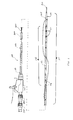
- FIG. 1 illustrates one example of a system for draining a fluid from a body cavity and/or infusing a fluid into the body cavity including a catheter, a support cannula, and a needle.
- FIG. 2 illustrates a distal portion of the catheter of FIG. 1 in a deployed configuration.
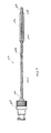
- FIG. 3 illustrates one example of a support cannula.
- FIG. 4 illustrates another example of a support cannula.
- FIG. 5 illustrates one example of a needle.
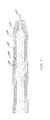
- FIG. 6 is a longitudinal cross sectional view of a distal portion of the system of FIG. 1 .
- FIG. 7 is a longitudinal cross sectional view of a distal portion of another example of a system for draining a fluid from a body cavity and/or infusing a fluid into the body cavity including a catheter, a support cannula, and a needle.
- proximal refers to a direction that is generally toward a physician during a medical procedure
- distal refers to a direction that is generally toward a target site within a patient's anatomy during a medical procedure.
- a drainage/infusion catheter for percutaneous placement within a body cavity to drain a fluid from the body cavity and/or to infuse a fluid into the body cavity.
- Such devices may be used in performing medical procedures such as, for example, cystostomy, nephrostomy, abscess drainage, biliary drainage, endopyelotomy, pericardial drainage, pleural drainage, spinal drainage, tracheotomy, enteral or tube feeding, urethral drainage, sinus drainage, or any other medical procedure involving drainage and/or introduction of a fluid from and/or into a body cavity.
- the body cavity may include any space within a body.
- the body cavity may include a bladder, a kidney, an abscess, a bile duct, a ureteropelvic junction, a body vessel (e.g., a blood vessel), or any other space within a body.
- the medical devices are described with respect to an exemplary loop catheter embodiment for drainage of a fluid from a body cavity. However, this disclosure is not so limited, and may be applicable to other types of drainage and/or infusion devices.
- the medical device may include a Foley catheter, a malecot catheter, a balloon catheter, an angled-tip catheter, or a straight catheter.
- FIG. 1 illustrates one example of a system for draining a fluid (e.g., excess fluid and/or infected fluid) from a body cavity and/or infusing a fluid (e.g., medication) into the body cavity.
- the system may include a catheter 100, a support cannula 200, and/or a needle 300.
- the support cannula 200 may be received within the catheter 100 to support at least a portion of the catheter as further described below.
- the needle 300 may be received within the support cannula 200 to aid in percutaneous placement of the catheter 100 as further described below.
- the catheter 100 may be placed within a body cavity to drain a fluid from the body cavity and/or to infuse a fluid into the body cavity.
- the catheter 100 may be similar to the catheter described in U.S. Patent No. 6,454,740 to Mody , which is incorporated by reference herein in its entirety.
- the catheter 100 may have any other suitable configuration for placement within a body cavity.
- the catheter 100 may include an elongate tubular member 102.
- a hub 104 may be positioned at the proximal end of the catheter 100.
- the tubular member 102 may include a proximal end 106 adjacent to the hub 104 and a distal end 108 positioned opposite the proximal end.
- the catheter 100 may include a tip 110 positioned at the distal end 108.
- the tip 110 may be configured as a pointed or tapered end of the tubular member 102 as shown in FIG. 1 .
- the tip 110 may be configured as a dilator tip to aid in dilating a puncture in a body tissue during percutaneous placement of the catheter 100 as further described below.
- the catheter 100 may include a body 112 extending proximally from the tip 110.
- the tubular member 102 of the catheter 100 may include the body 112 and the tip 110 extending distally from the body 112.
- a lumen may extend longitudinally within the catheter 100.
- the lumen of the catheter 100 may extend from a proximal end opening at the hub 104 to a distal end opening at the tip 110. Fluid may be passed out of and/or into the body cavity via the lumen of the catheter 100. Additionally, or alternatively, the support cannula 200 may be received within the lumen of the catheter 100 to provide support to the catheter during placement of the catheter within the body cavity as further described below.
- the tubular member 102 may include a retaining segment 114 positioned near the distal end 108 of the catheter 100.
- the retaining segment 114 may be configured as a segment of the catheter 100 extending proximally from the tip 110.
- the retaining segment 114 may include a portion of the body 112 of the tubular member 102 positioned near the distal end 108 of the catheter 100.
- the retaining segment 114 may include the distal portion of the body 112 and the tip 110.
- the retaining segment 114 may be configured to retain the catheter 100 in place within the body cavity as further described below. To that end, the retaining segment 114 may be movable between a delivery configuration and a deployed configuration.
- the retaining segment 114 may be substantially linear or rod-like as shown in FIG. 1 .
- the longitudinal axis of the tubular member 102 may be substantially linear along the retaining segment 114.
- the retaining segment 114 may be substantially non-linear as shown in FIG. 2 .
- the retaining segment 114 may include one or more loops formed in the tubular member 102 as shown in FIG. 2 .
- the retaining segment in the delivery configuration, may have a delivery width (e.g., the diameter of the catheter).
- the retaining segment may have a deployed width (e.g., the diameter of the loop, inflated balloon, expanded malecot, or other retaining mechanism) that is larger than the delivery width.
- the larger deployed width may be achieved, for example, by forming one or more loops as shown in FIG. 2 , inflating a balloon, expanding a malecot or barb, or any other suitable method of enlarging the diameter of the retaining segment.
- the retaining segment 114 may be biased toward the deployed configuration.
- the retaining segment 114 of the tubular member 102 may be preformed such that, in a relaxed condition, with the support cannula 200 and the needle 300 removed, the loops (or other retaining mechanism) are naturally formed.
- the support cannula 200 and/or the needle 300 may be received within the retaining segment 114 to retain the retaining segment in the delivery configuration for placement of the catheter 100 as further described below.
- FIG. 2 illustrates the retaining segment 114 as including two loops
- the retaining segment may include any number of loops (e.g., one, three, four, or more).
- the retaining segment, in the deployed configuration may have any other shape (e.g., J-shaped, helical, zig-zag, angled tip, or any other shape) configured to retain the catheter 100 in place within the body cavity.
- the retaining segment may include a barb, a malecot, a balloon, or any other suitable retaining mechanism configured to retain the catheter in place within the body cavity.
- the catheter 100 may include at least one aperture 116 disposed in the tubular member 102.
- the catheter 100 may include a plurality of apertures 116 as shown in FIGS. 1-2 .
- Each aperture 116 may extend through the sidewall of the tubular member 102 such that the lumen of the catheter 100 is in fluid communication with a point external of the catheter through the aperture.
- the plurality of apertures 116 may extend along a perforated segment 118 of the tubular member 102.
- the perforated segment 118 may extend longitudinally from a most proximal aperture 116 to a most distal aperture.
- the perforated segment 118 may be a portion of the body 112 of the tubular member 102 positioned near the distal end 108 of the catheter.
- the perforated segment 118 may be at least partially coextensive with the retaining segment 114.
- the apertures 116 may be longitudinally spaced from one another along the perforated segment 118. In one example, each aperture 116 may be longitudinally spaced from an adjacent aperture by a distance of about 0.5 in.
- Each aperture may be configured as a drainage/infusion port.
- excess fluid may migrate into the apertures 116 and travel proximally within the tubular member 102 and out through the hub 104.
- the excess fluid may flow by the force of gravity or may be extracted using a syringe or other device.
- a fluid may be introduced into the catheter through the hub 104 and flow distally within the tubular member 102 and out through the apertures 116. In this manner, the fluid may be infused into the body cavity.
- the fluid may be a medication which may assist in treating the patient.
- the fluid may be a medication which may assist in breaking up material contained within the body cavity so that the material may be withdrawn from the body cavity using the catheter 100.
- the plurality of apertures 116 may be aligned with one another with respect to a circumference of the tubular member 102. In other words, the plurality of apertures 116 may be radially aligned with one another as shown in FIGS. 1-2 .
- the plurality of apertures may be positioned on one side of the perforated segment 118 such that, in the deployed configuration, the apertures will not be blocked by an adjacent loop formed in the tubular member 102.
- the plurality of apertures 116 may include two or more sets of apertures. In one example, the plurality of apertures 116 may include two sets of apertures positioned opposite one another with respect to the circumference of the tubular member 102.
- the two sets of apertures may be diametrically opposed with respect to the tubular member 102.
- the plurality of apertures 116 may include one set of apertures positioned on each side of the loops formed in the tubular member 102 in the deployed configuration.
- the apertures 116 may be positioned at any other longitudinal and/or circumferential position along the tubular member 102.
- the apertures may be positioned in a linear arrangement, a helical arrangement, a random arrangement, or any other pattern or arrangement.
- the catheter 100 may include an actuating mechanism to aid in moving the retaining segment 114 between the delivery configuration and the deployed configuration.
- the actuating mechanism may include a thread extending from the hub 104 to a point at the distal end 108 of the catheter 100 and back to the hub as shown in FIG. 1 and described in U.S. Patent No. 6,454,740 to Mody , which is incorporated by reference herein in its entirety.
- the thread may extend through a plurality of holes in the tubular member such that pulling an end of the thread proximally relative to the tubular member 102 pulls the retaining segment 114 into the deployed configuration.
- the actuating mechanism may include an actuating member which may be positioned at the retaining segment 114 to bias the retaining segment toward the deployed configuration.
- the actuating member may include, for example, a wire or a tube formed from a superelastic or shape memory material.
- the retaining segment 114 may be preformed so that, in a relaxed condition, the retaining segment tends to move toward the deployed configuration.
- FIG. 3 illustrates one example of the support cannula 200.
- the support cannula may include an elongate tubular member 202.
- a hub 204 may be positioned at the proximal end of the support cannula 200.
- the tubular member 202 may include a proximal end 206 adjacent to the hub 204 and a distal end 208 positioned opposite the proximal end.
- the support cannula 200 may include a tip 210 positioned at the distal end 208.
- the support cannula 200 may include a body 212 extending proximally from the tip 210.
- the tubular member 202 of the support cannula 200 may include the body 212 and the tip 210 extending distally from the body 212.
- a lumen may extend longitudinally within the support cannula 200.
- the lumen of the support cannula 200 may extend from a proximal end opening at the hub 204 to a distal end opening at the
- the tubular member 202 of the support cannula 200 may be received within the lumen of the catheter 100 as shown in FIG. 1 .
- the length of the tubular member 202 may be shorter than or substantially equal to the length of the catheter 100 (e.g., the distance from the proximal end opening of the hub 104 to the distal end opening of the tip 110).
- the tip 210 of the support cannula 200 may be disposed within the catheter 100 as shown in FIG. 1 .
- the distal end of the tip 210 of the support cannula 200 may be longitudinally aligned with the distal end of the tip 110 of the catheter 100 (e.g., the distal end opening of the catheter).
- the hub 204 of the support cannula 200 may be engaged with the hub 104 of the catheter 100.
- the hub 204 of the support cannula 200 may be coupled to the hub 104 of the catheter 100 to couple the support cannula and the catheter to one another for delivery of the catheter to the body cavity.
- the hub 204 of the support cannula 200 may be threadably engaged with the hub 104 of the catheter to couple the support cannula and the catheter to one another.
- the hub 204 of the support cannula 200 and the hub 104 of the catheter 100 may include interlocking features (e.g., a notch and slot mechanism or a snap fit mechanism) which may engage one another to couple the support cannula and the catheter to one another.
- the support cannula and the catheter may be coupled to one another by any other suitable coupling mechanism.
- the tip 210 of the support cannula 200 may have a smaller outside diameter than the body 212 as shown in FIG. 3 .
- the tip 210 may include a tapered portion 210a adjacent to the body 212.
- An end portion 210b may extend distally from the tapered portion 210a.
- the tapered portion 210a may form a smooth transition between the larger diameter of the body 212 and the smaller diameter of the tip 210 (e.g., at the end portion 210b).
- the outer diameter of the end portion 210b may be substantially constant from the tapered portion to the distal end of the tip 210.
- the tapered portion 210a may have a substantially frustoconical shape.
- the end portion 210b may have a substantially cylindrical shape.
- the tapered portion and the end portion may have any suitable size and/or shape.
- the tapered portion 210a or the end portion 210b may be omitted.
- the tapered portion 210a may be omitted such that the end portion 210b extends from the proximal end to the distal end of the tip 210.
- the outer diameter of the tubular member 202 may transition in a stepwise manner from the larger outer diameter of the body 212 to the smaller outer diameter of the tip 210.
- the end portion 210b may be omitted such that the tapered portion 210a extends from the proximal end to the distal end of the tip 210.
- the outer diameter of the tip 210 may taper from the proximal end to the distal end of the tip 210.
- the tip 210 and the body 212 of the support cannula 200 may be formed as a unitary structure or as separate structures joined to one another to form the support cannula.
- the tip 210 may be formed at the distal end of a substantially cylindrical support cannula using any suitable method known in the art such as, for example, swaging, metal spinning, grinding, deep drawing, drilling, or any other method.
- the tip 210 may be attached to the body 212 using any suitable method known in the art such as, for example, soldering, gluing, welding, or any other method.
- the support cannula 200 may be received within the catheter 100 to support the catheter during placement within the body cavity as further described below.
- the body 212 of the support cannula 200 may be sized and shaped to be received within the body 112 of the catheter 100.
- a support segment of the body 112 may be positioned adjacent to the perforated portion 118 of the catheter 100 as further described below.
- the tip 210 of the support cannula 200 may be sized and shaped to be received within the tip 110 of the catheter 100.
- substantially the entire body 212 may be configured as a support segment 212a to support the body 112 of the catheter 100.
- the body 212 of the support cannula 200 may have a substantially constant outside diameter along the length of the body from the proximal end of the tubular member 202 to the tip 210 as shown in FIG. 3 .
- the body 212 of the support cannula 200 may include the support segment 212a and an extension segment 212b as shown in FIG. 4 .
- the support segment 212a may be positioned near the distal end 208 of the support catheter 200.
- the support segment 212a may be positioned adjacent to the tip 210 as shown in FIG. 4 .
- the extension segment 212b may be positioned proximal of the support segment 212a.
- the extension segment 212b may extend between the hub 204 and the support segment 212a.
- the extension segment 212b may be positioned between the hub 204 and the support segment 212a.
- the support segment 212a may be spaced longitudinally from the hub 204 for proper alignment with the catheter 100 (e.g., with the perforated segment 118) as further described below.
- the support segment 212a and the extension segment 212b may have any suitable lengths.
- the support segment 212a may have a length of between about 2 cm and about 7 cm, typically about 5 cm.
- the extension segment 212b may have a length of between about 16 cm and about 47 cm, typically about 31.5 cm.
- the length of the support segment 212a and/or the extension segment 212b may depend on factors including, for example, the length of the catheter, the length of the perforated segment, the length of the retaining segment, or the anatomy that is targeted in a procedure.
- the support segment 212a may have a larger outside diameter than the tip 210 as described above with reference to FIG. 3 .
- the extension segment 212b may have a smaller outside diameter than the support segment 212a as shown in FIG. 4 .
- the outer surface of the extension segment 212b may include a tapered portion that tapers from the smaller outside diameter of the extension segment to the larger outside diameter of the support segment 212a.
- the extension segment 212b may have a diameter that is substantially the same as the tip 210 (e.g., the end portion 210b). To that end, the extension segment 212b and the tip 210 may be formed from a substantially continuous first tubular member.
- the support segment 212a may be formed from a second tubular member having a larger diameter than the first tubular member.
- the second tubular member may be positioned around the first tubular member to form the tubular member 202 as shown in FIG. 4 .
- the first tubular member may be received within a lumen of the second tubular member to form the tubular member 202.
- the second tubular member may be fixedly attached to the first tubular member so that the position of the support segment 212a is fixed with respect to the tip 210.
- the tubular member 202 may be formed as a unitary member or from any number of separate components joined to one another to form the tubular member 202.
- the second tubular member may include a balloon mounted on the first tubular member. The balloon may movable between a deflated configuration and an inflated configuration. In this manner, the outer diameter of the support segment may be adjustable (e.g., by inflating and/or deflating the balloon).
- FIG. 5 illustrates one example of the needle 300.
- the needle 300 may include an elongate shaft member 302.
- a hub 304 may be positioned at the proximal end of the needle 300.
- the shaft member 302 may include a proximal end 306 adjacent to the hub 304 and a distal end 308 positioned opposite the proximal end.
- the needle 300 may include a tip 310 positioned at the distal end 308.
- the needle 300 may include a body 312 extending proximally from the tip 310.
- the shaft member 302 of the needle 300 may include the body 312 and the tip 310 extending distally from the body 312.
- the shaft member 302 of the needle 300 may be substantially solid.
- the shaft member 302 may be configured as a substantially solid rod.
- a lumen may extend longitudinally within the needle 300.
- the lumen of the needle 300 may extend from a proximal end opening at the hub 304 to a distal end opening at the tip 310.
- the shaft member 302 may be configured as a tubular member.
- a fluid e.g., contrast media
- the shaft member 302 of the needle 300 may be received within the lumen of the support cannula 200 as shown in FIG. 1 .
- the length of the shaft member 302 may be longer than the length of the support cannula 200 (e.g., the distance from the proximal end opening of the hub 204 to the distal end opening of the tip 210) and the length of the catheter 100.
- the tip 310 of the needle 300 may be disposed outside of the catheter 100 as shown in FIG. 1 .
- the shaft member 302 of the needle 300 may extend through the distal end opening of the support cannula 200 and the distal end opening of the catheter 100 so that the tip 310 is positioned distal of the tip 110 of the catheter as shown in FIG. 1 .
- the hub 304 of the needle 300 may be engaged with the hub 204 of the support cannula 200.
- the hub 304 of the needle 300 may be coupled to the hub 204 of the support cannula 200 to couple the needle and the support cannula to one another for delivery of the catheter 100 to the body cavity as described above with reference to the hub 204 of the support cannula 200 and the hub 104 of the catheter 100.
- the catheter 100, the support cannula 200, and the needle 300 may be formed from any suitable material known in the art.
- the tubular member 102 of the catheter 100 may be formed from a flexible polymeric material such as, for example polyurethane (e.g., ULTRATHANE® from Cook Medical, Bloomington, Indiana), silicone, nylon, or any combination thereof.
- the tubular member 202 of the support cannula 200 may be formed from a material having a greater stiffness than the tubular member 102 of the catheter 100.
- the tubular member 202 may be formed from stainless steel, nickel titanium alloy (e.g., nitinol), or any other suitable metallic material.
- the support segment 212a and the extension segment 212b may be formed from the same or different materials.
- the support segment 212a may be formed from polyvinyl chloride (PVC), nylon, polyether ether ketone (PEEK), stainless steel, or polytetrafluoroethylene (PTFE).
- the extension segment 212b may be formed from stainless steel.
- the shaft member 302 of the needle 300 may be formed from any suitable polymeric or metallic material as described with respect to the tubular body 102 of the catheter 100 and/or the tubular body 202 of the support cannula 200.
- the tubular member 102, the tubular member 202, and/or the shaft member 302 may be formed from polyurethane, silicone, nylon, polyamide, PVC, PEEK, PTFE, expanded polytetrafluoroethylene (ePTFE), polyethylene, stainless steel, nickel titanium alloy (e.g., nitinol), or any other suitable polymeric or metallic material.
- the hub 104 of the catheter 100, the hub 204 of the support cannula, and/or the hub 304 of the needle 300 may be formed from a semi-rigid material such as a semi-rigid plastic material.
- any portion of the catheter 100, the support cannula 200, and the needle 300 may be formed from any suitable material known in the art.
- FIG. 6 is a longitudinal cross sectional view of the distal portion of the system shown in FIG. 1 including the catheter 100, the support cannula 200 received within the catheter, and the needle 300 received within the support cannula.
- the lumen of the catheter may include a tip portion 122 and a body portion 124.
- the tip portion 122 of the catheter lumen may be positioned within the tip 110 of the tubular member 102 of the catheter 100.
- the body portion 124 of the catheter lumen may be positioned within the body 112 of the tubular member 102 of the catheter 100.
- the tip portion 122 and the body portion 124 may be in fluid communication with one another to collectively define a substantially continuous lumen extending longitudinally within the tubular member 102 of the catheter 100.
- the body 112 may include a distal end 126 as shown in FIG. 6 .
- the tip 110 may include a proximal end 128 and a distal end 130 opposite the proximal end.
- the proximal end 128 of the tip 110 may be positioned adjacent to the distal end 126 of the body 112.
- the proximal end 128 of the tip 110 and the distal end 126 of the body 112 may be contiguous with one another so that the tip extends distally from the body as described above.
- the tip 110 and the body 112 may be formed as a unitary structure (e.g., by molding or extrusion) or as separate structures joined to one another (e.g. by bonding).
- the tip portion 122 of the catheter lumen may include a proximal end longitudinally aligned with the proximal end 128 of the tip 110 and a distal end longitudinally aligned with the distal end 130 of the tip. In other words, the tip portion 122 may extend longitudinally from the proximal end 128 of the tip 110 to the distal end 130 of the tip. Additionally, or alternatively, the body portion 124 of the catheter lumen may include a distal end longitudinally aligned with the distal end 126 of the body 112.
- the catheter 100 with the support cannula 200 received within the catheter as shown in FIGS. 1 and 6 , may be in a non-expanded or non-stretched configuration.
- the support cannula 200 may be positioned within the lumen of the catheter 100 without expanding or stretching the sidewall of the tubular member 102 of the catheter.
- the catheter 100 and the support cannula 200 may be sized such that, upon introduction of the support cannula within the lumen of the catheter, the diameter of the catheter (e.g., the inner diameter of the body 112 and/or the inner diameter of the tip 110 as further described below) remains substantially unchanged.
- a diameter of at least a portion of the tip portion 122 of the lumen of the catheter 100 may be smaller than a diameter of the body portion 124 of the lumen of the catheter.
- the tip 110 of the catheter 100 may have an inner diameter that is smaller than an inner diameter of the body 112 of the catheter.
- the diameter of the body portion 124 of the lumen of the catheter 100 i.e., the inner diameter of the body 112
- the diameter of the tip portion 122 of the catheter lumen i.e., the inner diameter of the tip 110
- the tip portion 122 may have a first diameter at the proximal end 128 of the tip 110 and a second diameter at the distal end 130 of the tip.
- the first diameter may be larger than the second diameter.
- the first diameter may be substantially equal to the diameter of the body portion 124 of the catheter lumen.
- the tip portion 122 may taper from the first diameter to the second diameter as shown in FIG. 6 . In this manner, the lumen of the catheter 100 may taper from a larger diameter at the body portion 124 to a smaller diameter of the tip portion 122.
- the tip 110 may include a tapered segment 132 and an end segment 134 positioned distal of the tapered segment.
- the tapered segment 132 may extend distally from the proximal end 128 of the tip 110 to an intermediate point 136 of the tip.
- the tapered segment 132 may have a tapered inner diameter as shown in FIG. 6 .
- the inner diameter of the tip 110 may become increasingly smaller in a proximal to distal direction along the tapered segment 132.
- the inner diameter of the tip 110 may have a substantially uniform taper from the first diameter of the tip portion 122 at the proximal end 128 of the tip to the second diameter of the tip portion at the intermediate point 136 of the tip.
- the end segment 134 may extend distally from the tapered segment as shown in FIG. 6 . In other words, the end segment 134 may extend distally from the intermediate point 136 of the tip 110.
- the end segment 134 may have a substantially constant inner diameter as shown in FIG. 6 . In other words, the inner diameter of the end segment 134 may be substantially unvarying from the intermediate point 136 to the distal end 130 of the tip 110.
- the tip portion 122 of the catheter lumen may have a substantially cylindrical shape along the end segment 134.
- the tapered segment 132 or the end segment may be omitted.
- the tapered segment 132 may be omitted such that the end segment 134 extends from the proximal end 128 to the distal end 130 of the tip 110.
- the inner diameter of the tubular member 102 may transition in a stepwise manner from the larger inner diameter of the body 112 to the smaller inner diameter of the tip 110.
- the end segment 134 may be omitted such that the tapered segment 132 extends from the proximal end 128 to the distal end 130 of the tip 110.
- the inner diameter of the tip 110 may taper from the proximal end 128 to the distal end 130 of the tip 110.
- the support cannula 200 may be disposed within the lumen of the catheter 100 as shown in FIG. 6 .
- the support cannula 200 may aid in strengthening the catheter 100 (e.g., by supporting or reinforcing the tubular member 102) and/or straightening the catheter to retain the catheter in the delivery configuration for percutaneous placement of the catheter as further described below.
- At least a portion of the support cannula 200 may be sized and shaped to correspond to the inner diameter of the tubular member 102 of the catheter 100.
- at least a portion of the body 212 (e.g., the support segment 212a) of the support cannula 200 may have an outer diameter corresponding to the inner diameter of the body 112 of the catheter 100.
- the outer diameter of at least a portion of the body 212 of the support cannula 200 may be substantially equal to or slightly smaller than the inner diameter of the body 112 of the catheter 100.
- the support segment 212a of the body 212 may have an outer diameter corresponding to the inner diameter of the body 112 of the catheter 100.
- the support segment 212a of the body 212 may extend along substantially the entire length of the body 212 or along a portion of the length of the body 212 as described above with reference to FIGS. 3-4 .
- the outer surface of the support segment 212a may be in abutting contact with the inner surface of the body 112 of the catheter 100 as shown in FIG. 6 .
- the tip 210 of the support cannula 200 may have an outer diameter corresponding to the inner diameter of the tip 110 of the catheter 100.
- the outer diameter of at least a portion of the tip 210 of the support cannula 200 may be substantially equal to or slightly smaller than the inner diameter of the tip 110 of the catheter 100.
- the tapered portion 210a of the tip 210 of the support cannula 200 may be sized and shaped to correspond to the tapered segment 132 of the tip 110 of the catheter 100.
- the end portion 210b of the tip 210 of the support cannula 200 may be sized and shaped to correspond to the end segment 134 of the tip 110 of the catheter 100.
- the outer diameter of the tip 210 of the support cannula 200 may correspond to the inner diameter of the tip 110 of the catheter 100 along substantially the entire length of the tip 210 of the support cannula as shown in FIG. 6 . This may enable the tip 210 of the support cannula 200 to support and/or straighten the tip 110 of the catheter 100 along substantially the entire length of the catheter tip.
- the support segment 212a of the support cannula 200 may be positioned within the perforated segment 118 of the body 112 of the catheter 100.
- the support segment 212a may extend proximally from the tip 210 to at least the proximal end of the perforated segment 118 of the catheter 100.
- the proximal end of the support segment 212a may be longitudinally aligned with or positioned proximal of the proximal end of the perforated segment 118 of the catheter 100. This may enable the support segment 212a of the support cannula 200 to support the body 112 of the catheter 100 along substantially the entire length of the perforated segment 118.
- the support cannula 200 may be received within the catheter 100 to retain the catheter in the delivery configuration.
- the support cannula 200 may have a stiffness that is greater than a stiffness of the catheter 100.
- the support cannula 200 may be substantially linear in a relaxed configuration.
- Introduction of the support cannula 200 into the lumen of the catheter 100 may cause the catheter to straighten into the delivery configuration.
- introduction of the support cannula 200 into the lumen of the catheter 100 may cause the retaining segment 114 of the catheter to unroll from the deployed configuration shown in FIG. 2 to the delivery configuration shown in FIG. 1 .
- the tip 210 of the support cannula 200 may be received within the tip 110 of the catheter 100 as described above. In this manner, introduction of the support cannula 200 into the lumen of the catheter 100 may cause the tip 110 of the catheter to straighten as shown in FIG. 1 .
- the support cannula 200 may be received within the catheter 100 to support at least a portion of the catheter for placement within the body cavity.
- the support cannula 200 may be in contact with the inner surface of the catheter 100 (e.g., along the perforated segment 118 of the body 112 and/or along the tip 110) as described above.
- the catheter 100 with the support segment 200 received therein may be stronger (e.g., may have a greater rigidity and/or column strength) than the unsupported catheter. Such greater strength may reduce the tendency of the catheter 100 to buckle in response to exertion of a longitudinal force on the catheter. Such a longitudinal force may be exerted on the catheter 100 during percutaneous placement of the catheter as described below.
- the perforated segment 118 of the body 112 of the catheter 100 may be weaker (e.g., less rigid) than the remainder of the body 112. This may be caused by the apertures 116 disposed in the perforated segment of the body 112. In other words, the perforated segment 118 of the body 112 may be less rigid than an unperforated segment of the body 112.
- the support segment 212a of the support cannula 200 may extend longitudinally along substantially the entire length of the perforated segment 118 as described above. In this manner, the support segment 212a may provide support to the catheter 100 along substantially the entire length of the perforated segment 118.
- the tip 210 of the support cannula 200 may be received within the tip 110 of the catheter 100 as described above. In this manner, the support cannula 200 may support the catheter 100 along substantially the entire length of the tip 110 of the catheter.
- the support cannula 200 and the needle 300 may be disposed within the lumen of the catheter 100 as shown in FIGS. 1 and 6 to retain the catheter in the delivery configuration for percutaneous placement of the catheter 100.
- the hub 204 of the support cannula 200 may be engaged with the hub 104 of the catheter 100 as described above. In this manner, longitudinal translation of the support cannula 200 relative to the catheter 100 may be inhibited.
- the hub 304 of the needle may be engaged with the hub 204 of the support cannula 200 as described above. In this manner, longitudinal translation of the needle 300 relative to the support cannula 200 may be inhibited.
- the tip 310 of the needle 300 may be passed through a body tissue (e.g., the patient's skin) to form a puncture in the body tissue.
- the needle 300, the support cannula 200, and the catheter 100 may be advanced distally until the tip 110 of the catheter contacts the body tissue.
- the needle 300, the support cannula 200, and the catheter 100 may be advanced further distally so that the tip 110 of the catheter enters the body tissue through the puncture.
- the tapered outer surface of the tip 110 of the catheter 100 may gradually dilate the puncture in the body tissue during introduction of the catheter through the body tissue. In other words, the puncture may be gradually enlarged by passage of the tip 110 of the catheter therethrough.
- the needle 300 may be retracted proximally relative to the support cannula 200 and removed from the lumen of the support cannula.
- the support cannula 200 and the catheter 100 may be advanced further distally until the retaining segment 114 of the catheter is positioned within the body cavity.
- the support cannula 200 may be retracted proximally relative to the catheter 100 and removed from the lumen of the catheter.
- the catheter 100 and/or the support cannula 200 may include a low friction material, which may reduce the friction between the catheter and the support cannula.
- the low friction material may include a non-stick material such as, for example, PTFE, sodium bicarbonate, a silicone lubricant, or any other biocompatible lubricant.
- the catheter 100 and/or the support cannula 200 may be formed from the low friction material.
- the catheter 100 and/or the support cannula 200 may include a layer of low friction material (e.g., along the inner surface of the catheter and/or the outer surface of the support cannula).
- the outer surface of the support segment 212a may include the low friction material. The low friction material may reduce the force that may be required to remove the support cannula from the catheter and/or prevent the support cannula and the catheter from sticking to one another.
- the support segment 212a of the support cannula 200 may include a balloon as described above.
- the balloon may be inflated to support the catheter 100 during percutaneous placement of the catheter as described above.
- the balloon may be deflated for removal of the support cannula 200 from the catheter. Deflating the balloon may reduce the frictional force between the support cannula 200 and the catheter 100 (e.g., by reducing the surface area of the support cannula which may be in contact with the catheter), which may aid in removing the support cannula from the catheter.
- the catheter 100 may move toward the deployed configuration as described above.
- the loops (or other retaining mechanism) may be formed in the retaining segment as described above. This may prevent the catheter 100 from moving proximally out of the body cavity so that the catheter remains in place within the body cavity for drainage and/or infusion of fluid out of and/or into the body cavity.
- a guide wire may be introduced through the body tissue (e.g., using the Seldinger technique) and advanced into the body cavity.
- the support cannula 200 may be disposed within the lumen of the catheter 100, and the needle 300 may be omitted.
- the support cannula 200 and the catheter 100 may be advanced distally over the guide wire to introduce the catheter through the body tissue and into the body cavity.
- the guide wire may be received within the lumen of the support cannula 200, and the support cannula and the catheter 100 may be advanced distally relative to the guide wire to introduce the catheter into the body cavity.
- the guide wire and the support cannula 200 may be retracted proximally and removed from the catheter 100 to enable the catheter to move to the deployed configuration as described above.
- the support cannula 200 may strengthen the catheter 100 as described above to prevent the catheter from buckling or kinking (e.g., folding like an accordion) upon passage through the puncture in the body tissue. This may help to avoid damaging the catheter 100 upon introduction into the body cavity. Additionally, or alternatively, this may reduce the force required to pass the catheter 100 through the body tissue and/or improve the accuracy of the placement of the catheter. In other words, this may improve the ease of percutaneous placement of the catheter 100 (e.g., because the relatively smooth, unbuckled catheter body may be more effectively guided through the body tissue than a buckled or folded catheter body). Additionally, or alternatively, this may reduce the trauma experienced by the patient during placement of the catheter 100.
- buckling or kinking e.g., folding like an accordion
- the support provided by the support cannula 200 may enable the body 112 and/or the tip 110 of the catheter 100 to be formed from a relatively soft material (e.g., a low durometer polyurethane, silicone, nylon, or a blend of a polymeric material and an elastic material).
- a relatively soft material e.g., a low durometer polyurethane, silicone, nylon, or a blend of a polymeric material and an elastic material.
- the body 112 and/or the tip 110 of the catheter 100 may be formed from a material having a durometer of less than about 95A, typically between about 90A and about 95A. In another example, the body 112 and/or the tip 110 of the catheter 100 may be formed from a material having a durometer of less than about 85A, typically between about 80A and about 85A. In another example, the body 112 and/or the tip 110 of the catheter 100 may be formed from a material having a durometer of less than about 80A, typically between about 70A and about 77A.
- the outer diameter of the support segment 212a may correspond to the inner diameter of the perforated segment 118
- the outer diameter of the tapered portion 210a of the tip 210 may correspond to the inner diameter of the tapered segment 132 of the tip 110
- the outer diameter of the end portion 210b of the tip 210 may correspond to the inner diameter of the end segment 134 of the tip 110 as shown in FIG. 6 and described above.
- the outer diameter of the support cannula 200 may correspond to the inner diameter of the catheter 100 along substantially the entire length of the perforated segment 118 of the body 112 and the tip 110.
- This configuration of the support cannula 200 may help to more effectively straighten the catheter 100 as compared to a conventional support cannula having a substantially cylindrical shape along the entire length of the cannula body. In this manner, the support cannula 200 may be configured to more effectively retain the catheter in the delivery configuration shown in FIG. 1 and/or strengthen the catheter.
- a conventional support cannula may have a substantially cylindrical shape with an outer diameter corresponding to the inner diameter of the catheter body, which may be larger than the inner diameter of the catheter tip.
- the conventional support cannula may have a relatively large gauge size.
- the support cannula may be unable to fit within the smaller diameter tip portion of the catheter lumen. Accordingly, the catheter tip may not be straightened or supported by the conventional support cannula. Not fully straightening the tip of the catheter may be problematic in that the physician may attempt to straighten the catheter tip by hand and potentially be punctured.
- the needle may puncture through the sidewall of the catheter tip which may be curved and/or unprotected by the support cannula. Additionally, or alternatively, the curved catheter tip may be difficult to pass through the body tissue during percutaneous placement of the catheter.
- a conventional support cannula may have a substantially cylindrical shape with an outer diameter corresponding to the smaller inner diameter of the catheter tip.
- the conventional support cannula may have a relatively small gauge size.
- the support cannula may not be in contact with the inner surface of the perforated segment of the catheter body.
- the conventional support cannula may not support the perforated segment of the catheter body. This may enable the catheter body to buckle during percutaneous placement of the catheter.
- FIG. 7 is a longitudinal cross sectional view of a distal portion of a system including the catheter 100, the support cannula 200 received within the catheter, and another example of the needle 300 received within the support cannula.
- the outer diameter of the needle 300 may vary longitudinally along the length of the needle as shown in FIG. 7 .
- the needle 300 may include a first longitudinal segment 314 disposed within the body 212 of the support cannula and a second longitudinal segment 316 disposed within the tip 210 of the support cannula.
- the first longitudinal segment 314 of the needle 300 may have an outer diameter corresponding to the inner diameter of the body 212 of the support cannula 200.
- the second longitudinal segment 316 of the needle 300 may have an outer diameter corresponding to the inner diameter of the tip 210 of the support cannula 200. To that end, at least a portion of the second longitudinal segment 316 may be tapered to correspond to the tapered portion 210a of the tip 210. Additionally, or alternatively, at least a portion of the second longitudinal segment 316 may have a substantially cylindrical shape to correspond to the end portion 210b of the tip 210. Additionally, or alternatively, the second longitudinal segment 316 may extend distally beyond the distal end of the support cannula 200 to the sharpened tip 310 of the needle 300.
- the outer diameter of the needle 300 may correspond to the inner diameter of the support cannula 200 along substantially the entire length of the tubular member 202 of the support cannula. In this manner, the needle 300 may contact the inner surface of the support cannula 200 to provide support to the support cannula for percutaneous placement of the catheter 100. Additionally, or alternatively, the larger diameter of the first longitudinal segment 314 of the needle 300 compared to the second longitudinal segment 316 may help to prevent the support cannula 200 from moving proximally relative to the needle 300 during percutaneous placement of the catheter 100.
- a system comprising:
- the plurality of apertures comprises a first set of apertures extending along the length of the perforated segment of the catheter body and a second set of apertures extending along the length of the perforated segment of the catheter body, and the first set of apertures and the second set of apertures are spaced from one another with respect to a circumference of the catheter body.
- the aperture comprises a plurality of apertures spaced from one another along a length of the perforated segment of the catheter body, and the support segment extends proximally from the tip of the support cannula to at least a position longitudinally aligned with a most proximal of the plurality of apertures.
- a distal portion of the catheter comprises a retaining member, and the retaining member is movable between a delivery configuration and a retaining configuration to retain the catheter in place within a body cavity.
- a system comprising:
- the cannula tip comprises a first outer diameter that is substantially equal to the outer diameter of the support segment and a second outer diameter that is smaller than the first outer diameter and corresponds to the inner diameter of the catheter tip, and the cannula tip tapers from the first outer diameter to the second outer diameter.
- the cannula tip comprises a tapered portion and an end portion extending distally from the tapered portion, the tapered portion tapers from the first outer diameter to the second outer diameter, and the end portion comprises a substantially constant outer diameter.
- the catheter tip comprises a tapered segment comprising an inner diameter that tapers from a first inner diameter that is substantially equal to the inner diameter of the catheter body to a second inner diameter that is smaller than the inner diameter of the catheter body.
- the catheter tip comprises an end segment extending distally from the tapered segment and comprising a substantially constant inner diameter that is substantially equal to the second inner diameter of the tapered segment.
Landscapes
- Health & Medical Sciences (AREA)
- Life Sciences & Earth Sciences (AREA)
- Animal Behavior & Ethology (AREA)
- Veterinary Medicine (AREA)
- Public Health (AREA)
- Engineering & Computer Science (AREA)
- Biomedical Technology (AREA)
- Heart & Thoracic Surgery (AREA)
- General Health & Medical Sciences (AREA)
- Anesthesiology (AREA)
- Hematology (AREA)
- Surgery (AREA)
- Pulmonology (AREA)
- Biophysics (AREA)
- Pathology (AREA)
- Nuclear Medicine, Radiotherapy & Molecular Imaging (AREA)
- Medical Informatics (AREA)
- Molecular Biology (AREA)
- Otolaryngology (AREA)
- Gastroenterology & Hepatology (AREA)
- Media Introduction/Drainage Providing Device (AREA)
Abstract
Description
- This application claims priority from
U.S. Provisional Application No. 61/728,099, filed on November 19, 2012 - This disclosure relates generally to medical devices. More specifically, this disclosure relates to drainage/infusion catheters for percutaneous placement within a body cavity to drain a fluid from the body cavity and/or to infuse a fluid into the body cavity.
- The use of catheters for draining excess or infected body fluids from a body cavity or for infusing medication into a body cavity is well known. One use of the catheter may be to drain excess fluid. For example, the catheter may be used to drain urine from the kidney when there is an obstruction in the ureter. Another use of the catheter may be to drain fluid from an infected collection. For example, the catheter may be used to drain pus from an abdominal abscess. Once in position, the flexible distal portion at the end of the catheter may be altered to help to maintain the flexible distal portion within the body cavity. For example, one or more loops may be imparted at the distal flexible end of the catheter. These loops may be much larger than the hole through which the catheter is inserted. This may help to retain the catheter in the body cavity, which may help to prevent inadvertent removal of the catheter from the body cavity. Excess or infected fluid may enter a port or hole in the tubular member of the catheter and be withdrawn from the body cavity by aspiration or by gravity.
- Typically, inserting the drainage catheter into the body cavity is done with the aid of an insertion tool, such as a stiffening cannula. The stiffening cannula may be inserted into the drainage catheter to support the drainage catheter and/or to at least partially straighten the loops at the distal flexible end of the catheter for placement in the body cavity. Typically, the stiffening cannula has a cylindrical shape with an outer diameter that is either larger than the inner diameter of the tip of the drainage catheter (which may be tapered) or smaller than the inner diameter of the body of the drainage catheter. A large gauge stiffening cannula may be unable to fit within the tip of the drainage catheter, which may result in a failure to straighten and/or support the tip of the drainage catheter. A small gauge stiffening cannula may not fully contact the inner surface of the body of the drainage catheter, which may result in a failure to support the body of the catheter. Failure to support and/or straighten the drainage catheter may result in damage to the drainage catheter caused by buckling and/or puncturing of the drainage catheter during insertion of the drainage catheter into the body cavity.
- The present embodiments provide a drainage/infusion catheter for percutaneous placement within a body cavity to drain a fluid from the body cavity and/or to infuse a fluid into the body cavity.
- In one example, a system may include a catheter and an elongate tubular support cannula. The catheter may include an elongate tubular member including a proximal end, a distal end, a lumen extending longitudinally within the catheter, a tapered tip positioned at the distal end of the catheter, and a body extending proximally from the tip. The tip of the catheter may have an inner diameter that is smaller than an inner diameter of the body of the catheter. The support cannula may be slidably received within the lumen of the catheter. The support cannula may include a proximal end, a distal end, a lumen extending longitudinally within the support cannula, a tip positioned at the distal end of the support cannula and disposed within the tip of the catheter such that the tip of the support cannula does not extend distally beyond the distal end of the catheter, and a support segment extending proximally from the tip of the support cannula and disposed within the body of the catheter such that the body of the catheter remains in a non-stretched configuration. The tip of the support cannula may have an outer diameter corresponding to the inner diameter of the tip of the catheter. The support segment may have an outer diameter corresponding to the inner diameter of the body of the catheter. The body of the catheter may include a perforated segment including an aperture disposed in the catheter and in fluid communication with the lumen of the catheter. The support segment of the support cannula may extend from the tip of the support cannula to at least a position longitudinally adjacent to a proximal end of the perforated segment.
- In another example, a system may include a catheter, an elongate tubular support cannula, and an elongate needle. The catheter may include an elongate tubular member including a proximal end, a distal end, a catheter lumen extending longitudinally within the catheter, a catheter body, and a catheter tip extending distally from the catheter body. The catheter tip may include a tapered outer surface and an inner diameter that is smaller than an inner diameter of the catheter body. The support cannula may be slidably received within the catheter lumen and include a proximal end, a distal end, a cannula lumen extending longitudinally within the support cannula, a support segment disposed within the catheter body, and a cannula tip extending distally from the support segment and disposed within the catheter tip. The support segment may include an outer diameter that is substantially constant along a length of the support segment and corresponds to the inner diameter of the catheter body. The cannula tip may include an outer diameter that is smaller than the outer diameter of the support segment and corresponds to the inner diameter of the catheter tip. The needle may be slidably received within the cannula lumen and include a proximal end, a distal end, and a sharpened tip positioned at the distal end of the needle and disposed distal of the distal end of the catheter. The catheter body may include a perforated segment including a plurality of apertures in fluid communication with the catheter lumen and longitudinally spaced from one another along a length of the perforated segment. The support segment may be disposed within the perforated segment of the catheter body and may extend proximally from the cannula tip to at least a position longitudinally aligned with a proximal end of the perforated segment.
- In another example, a method for percutaneous placement of a catheter into a body cavity may include providing the catheter and a support cannula. Alternatively, the method may be for preparing a catheter for percutaneous placement into a body cavity, or for providing an assembly including a catheter and a support cannula, adapted for percutaneous placement of said catheter into a body cavity. The catheter may include a catheter body and a catheter tip extending distally from the catheter body. The catheter tip may have an inner diameter that is smaller than an inner diameter of the catheter body. The support cannula may include a support segment and a cannula tip extending distally from the support segment. The support segment may have an outer diameter corresponding to the inner diameter of the catheter body. The cannula tip may have an outer diameter corresponding to the inner diameter of the catheter tip. The method may include positioning the support cannula within a lumen of the catheter. The support segment may be in contact with an inner surface of a perforated segment of the catheter body along substantially an entire length of the perforated segment. The perforated segment may include a plurality of apertures in fluid communication with the lumen of the catheter and longitudinally spaced from one another along the length of the perforated segment. The cannula tip may be in contact with an inner surface of the catheter tip. A distal end of the support cannula may be disposed within the catheter tip. The method may include advancing the catheter and the support cannula distally through a puncture in a body tissue.
- Other systems, methods, features, and advantages of the invention will be, or will become, apparent to one with skill in the art upon examination of the following figures and detailed description. It is intended that all such additional systems, methods, features, and advantages be within the scope of the invention, and be encompassed by the following claims.
-
FIG. 1 illustrates one example of a system for draining a fluid from a body cavity and/or infusing a fluid into the body cavity including a catheter, a support cannula, and a needle. -
FIG. 2 illustrates a distal portion of the catheter ofFIG. 1 in a deployed configuration. -
FIG. 3 illustrates one example of a support cannula. -
FIG. 4 illustrates another example of a support cannula. -
FIG. 5 illustrates one example of a needle. -
FIG. 6 is a longitudinal cross sectional view of a distal portion of the system ofFIG. 1 . -
FIG. 7 is a longitudinal cross sectional view of a distal portion of another example of a system for draining a fluid from a body cavity and/or infusing a fluid into the body cavity including a catheter, a support cannula, and a needle. - Detailed embodiments of the present invention are disclosed herein. It is understood, however, that the disclosed embodiments are merely exemplary of the invention, which may be embodied in various and alternative forms. The figures are not necessarily to scale, and some figures may be configured to show the details of a particular component. Therefore, specific structural and functional details disclosed herein are not to be interpreted as limiting, but merely as a representative basis for the claims and for teaching one skilled in the art to practice the present invention.
- In the present disclosure, the term "proximal" refers to a direction that is generally toward a physician during a medical procedure, while the term "distal" refers to a direction that is generally toward a target site within a patient's anatomy during a medical procedure.
- Various medical devices for introduction and/or implantation in a body cavity are disclosed herein. Preferred embodiments relate to a drainage/infusion catheter for percutaneous placement within a body cavity to drain a fluid from the body cavity and/or to infuse a fluid into the body cavity. Such devices may be used in performing medical procedures such as, for example, cystostomy, nephrostomy, abscess drainage, biliary drainage, endopyelotomy, pericardial drainage, pleural drainage, spinal drainage, tracheotomy, enteral or tube feeding, urethral drainage, sinus drainage, or any other medical procedure involving drainage and/or introduction of a fluid from and/or into a body cavity. The body cavity may include any space within a body. For example, the body cavity may include a bladder, a kidney, an abscess, a bile duct, a ureteropelvic junction, a body vessel (e.g., a blood vessel), or any other space within a body. The medical devices are described with respect to an exemplary loop catheter embodiment for drainage of a fluid from a body cavity. However, this disclosure is not so limited, and may be applicable to other types of drainage and/or infusion devices. For example, the medical device may include a Foley catheter, a malecot catheter, a balloon catheter, an angled-tip catheter, or a straight catheter.
-
FIG. 1 illustrates one example of a system for draining a fluid (e.g., excess fluid and/or infected fluid) from a body cavity and/or infusing a fluid (e.g., medication) into the body cavity. The system may include acatheter 100, asupport cannula 200, and/or aneedle 300. Thesupport cannula 200 may be received within thecatheter 100 to support at least a portion of the catheter as further described below. Theneedle 300 may be received within thesupport cannula 200 to aid in percutaneous placement of thecatheter 100 as further described below. - At least a portion of the
catheter 100 may be placed within a body cavity to drain a fluid from the body cavity and/or to infuse a fluid into the body cavity. In one example, thecatheter 100 may be similar to the catheter described inU.S. Patent No. 6,454,740 to Mody , which is incorporated by reference herein in its entirety. In other examples, thecatheter 100 may have any other suitable configuration for placement within a body cavity. To that end, thecatheter 100 may include an elongatetubular member 102. Ahub 104 may be positioned at the proximal end of thecatheter 100. Thetubular member 102 may include aproximal end 106 adjacent to thehub 104 and adistal end 108 positioned opposite the proximal end. Thecatheter 100 may include atip 110 positioned at thedistal end 108. Thetip 110 may be configured as a pointed or tapered end of thetubular member 102 as shown inFIG. 1 . In other words, thetip 110 may be configured as a dilator tip to aid in dilating a puncture in a body tissue during percutaneous placement of thecatheter 100 as further described below. Thecatheter 100 may include abody 112 extending proximally from thetip 110. In other words, thetubular member 102 of thecatheter 100 may include thebody 112 and thetip 110 extending distally from thebody 112. A lumen may extend longitudinally within thecatheter 100. For example, the lumen of thecatheter 100 may extend from a proximal end opening at thehub 104 to a distal end opening at thetip 110. Fluid may be passed out of and/or into the body cavity via the lumen of thecatheter 100. Additionally, or alternatively, thesupport cannula 200 may be received within the lumen of thecatheter 100 to provide support to the catheter during placement of the catheter within the body cavity as further described below. - The
tubular member 102 may include a retainingsegment 114 positioned near thedistal end 108 of thecatheter 100. In one example, the retainingsegment 114 may be configured as a segment of thecatheter 100 extending proximally from thetip 110. In other words, the retainingsegment 114 may include a portion of thebody 112 of thetubular member 102 positioned near thedistal end 108 of thecatheter 100. In another example, the retainingsegment 114 may include the distal portion of thebody 112 and thetip 110. The retainingsegment 114 may be configured to retain thecatheter 100 in place within the body cavity as further described below. To that end, the retainingsegment 114 may be movable between a delivery configuration and a deployed configuration. In the delivery configuration, the retainingsegment 114 may be substantially linear or rod-like as shown inFIG. 1 . In other words, the longitudinal axis of thetubular member 102 may be substantially linear along the retainingsegment 114. In the deployed configuration, the retainingsegment 114 may be substantially non-linear as shown inFIG. 2 . For example, the retainingsegment 114 may include one or more loops formed in thetubular member 102 as shown inFIG. 2 . - Additionally, or alternatively, in the delivery configuration, the retaining segment may have a delivery width (e.g., the diameter of the catheter). In the deployed configuration, the retaining segment may have a deployed width (e.g., the diameter of the loop, inflated balloon, expanded malecot, or other retaining mechanism) that is larger than the delivery width. The larger deployed width may be achieved, for example, by forming one or more loops as shown in
FIG. 2 , inflating a balloon, expanding a malecot or barb, or any other suitable method of enlarging the diameter of the retaining segment. - In one example, the retaining
segment 114 may be biased toward the deployed configuration. In other words, the retainingsegment 114 of thetubular member 102 may be preformed such that, in a relaxed condition, with thesupport cannula 200 and theneedle 300 removed, the loops (or other retaining mechanism) are naturally formed. Thesupport cannula 200 and/or theneedle 300 may be received within the retainingsegment 114 to retain the retaining segment in the delivery configuration for placement of thecatheter 100 as further described below. - Although
FIG. 2 illustrates the retainingsegment 114 as including two loops, this disclosure is not so limited. In other examples, the retaining segment may include any number of loops (e.g., one, three, four, or more). Additionally, or alternatively, the retaining segment, in the deployed configuration, may have any other shape (e.g., J-shaped, helical, zig-zag, angled tip, or any other shape) configured to retain thecatheter 100 in place within the body cavity. Additionally, or alternatively, the retaining segment may include a barb, a malecot, a balloon, or any other suitable retaining mechanism configured to retain the catheter in place within the body cavity. - The
catheter 100 may include at least oneaperture 116 disposed in thetubular member 102. In one example, thecatheter 100 may include a plurality ofapertures 116 as shown inFIGS. 1-2 . Eachaperture 116 may extend through the sidewall of thetubular member 102 such that the lumen of thecatheter 100 is in fluid communication with a point external of the catheter through the aperture. The plurality ofapertures 116 may extend along aperforated segment 118 of thetubular member 102. Theperforated segment 118 may extend longitudinally from a mostproximal aperture 116 to a most distal aperture. Theperforated segment 118 may be a portion of thebody 112 of thetubular member 102 positioned near thedistal end 108 of the catheter. Additionally, or alternatively, theperforated segment 118 may be at least partially coextensive with the retainingsegment 114. Theapertures 116 may be longitudinally spaced from one another along theperforated segment 118. In one example, eachaperture 116 may be longitudinally spaced from an adjacent aperture by a distance of about 0.5 in. - Each aperture may be configured as a drainage/infusion port. To that end, when the
catheter 100 is placed within the body cavity, excess fluid may migrate into theapertures 116 and travel proximally within thetubular member 102 and out through thehub 104. The excess fluid may flow by the force of gravity or may be extracted using a syringe or other device. Additionally, or alternatively, a fluid may be introduced into the catheter through thehub 104 and flow distally within thetubular member 102 and out through theapertures 116. In this manner, the fluid may be infused into the body cavity. In one example, the fluid may be a medication which may assist in treating the patient. For example, the fluid may be a medication which may assist in breaking up material contained within the body cavity so that the material may be withdrawn from the body cavity using thecatheter 100. - In one example, the plurality of
apertures 116 may be aligned with one another with respect to a circumference of thetubular member 102. In other words, the plurality ofapertures 116 may be radially aligned with one another as shown inFIGS. 1-2 . The plurality of apertures may be positioned on one side of theperforated segment 118 such that, in the deployed configuration, the apertures will not be blocked by an adjacent loop formed in thetubular member 102. Additionally, or alternatively, the plurality ofapertures 116 may include two or more sets of apertures. In one example, the plurality ofapertures 116 may include two sets of apertures positioned opposite one another with respect to the circumference of thetubular member 102. In other words, the two sets of apertures may be diametrically opposed with respect to thetubular member 102. In this manner, the plurality ofapertures 116 may include one set of apertures positioned on each side of the loops formed in thetubular member 102 in the deployed configuration. In other examples, theapertures 116 may be positioned at any other longitudinal and/or circumferential position along thetubular member 102. For example, the apertures may be positioned in a linear arrangement, a helical arrangement, a random arrangement, or any other pattern or arrangement. - The
catheter 100 may include an actuating mechanism to aid in moving the retainingsegment 114 between the delivery configuration and the deployed configuration. In one example, the actuating mechanism may include a thread extending from thehub 104 to a point at thedistal end 108 of thecatheter 100 and back to the hub as shown inFIG. 1 and described inU.S. Patent No. 6,454,740 to Mody , which is incorporated by reference herein in its entirety. The thread may extend through a plurality of holes in the tubular member such that pulling an end of the thread proximally relative to thetubular member 102 pulls the retainingsegment 114 into the deployed configuration. In other examples, the actuating mechanism may include an actuating member which may be positioned at the retainingsegment 114 to bias the retaining segment toward the deployed configuration. The actuating member may include, for example, a wire or a tube formed from a superelastic or shape memory material. In other examples, the retainingsegment 114 may be preformed so that, in a relaxed condition, the retaining segment tends to move toward the deployed configuration. -
FIG. 3 illustrates one example of thesupport cannula 200. The support cannula may include an elongatetubular member 202. Ahub 204 may be positioned at the proximal end of thesupport cannula 200. Thetubular member 202 may include aproximal end 206 adjacent to thehub 204 and adistal end 208 positioned opposite the proximal end. Thesupport cannula 200 may include atip 210 positioned at thedistal end 208. Thesupport cannula 200 may include abody 212 extending proximally from thetip 210. In other words, thetubular member 202 of thesupport cannula 200 may include thebody 212 and thetip 210 extending distally from thebody 212. A lumen may extend longitudinally within thesupport cannula 200. For example, the lumen of thesupport cannula 200 may extend from a proximal end opening at thehub 204 to a distal end opening at thetip 210. - The
tubular member 202 of thesupport cannula 200 may be received within the lumen of thecatheter 100 as shown inFIG. 1 . In one example, the length of thetubular member 202 may be shorter than or substantially equal to the length of the catheter 100 (e.g., the distance from the proximal end opening of thehub 104 to the distal end opening of the tip 110). In this manner, thetip 210 of thesupport cannula 200 may be disposed within thecatheter 100 as shown inFIG. 1 . In one example, the distal end of thetip 210 of the support cannula 200 (e.g., the distal end opening of the support cannula) may be longitudinally aligned with the distal end of thetip 110 of the catheter 100 (e.g., the distal end opening of the catheter). Additionally, or alternatively, thehub 204 of thesupport cannula 200 may be engaged with thehub 104 of thecatheter 100. In one example, thehub 204 of thesupport cannula 200 may be coupled to thehub 104 of thecatheter 100 to couple the support cannula and the catheter to one another for delivery of the catheter to the body cavity. For example, thehub 204 of thesupport cannula 200 may be threadably engaged with thehub 104 of the catheter to couple the support cannula and the catheter to one another. In another example, thehub 204 of thesupport cannula 200 and thehub 104 of thecatheter 100 may include interlocking features (e.g., a notch and slot mechanism or a snap fit mechanism) which may engage one another to couple the support cannula and the catheter to one another. In other examples, the support cannula and the catheter may be coupled to one another by any other suitable coupling mechanism. - The
tip 210 of thesupport cannula 200 may have a smaller outside diameter than thebody 212 as shown inFIG. 3 . In one example, thetip 210 may include a taperedportion 210a adjacent to thebody 212. An end portion 210b may extend distally from the taperedportion 210a. The taperedportion 210a may form a smooth transition between the larger diameter of thebody 212 and the smaller diameter of the tip 210 (e.g., at the end portion 210b). The outer diameter of the end portion 210b may be substantially constant from the tapered portion to the distal end of thetip 210. In one example, the taperedportion 210a may have a substantially frustoconical shape. Additionally, or alternatively, the end portion 210b may have a substantially cylindrical shape. In other examples, the tapered portion and the end portion may have any suitable size and/or shape. In other examples, the taperedportion 210a or the end portion 210b may be omitted. For example, the taperedportion 210a may be omitted such that the end portion 210b extends from the proximal end to the distal end of thetip 210. The outer diameter of thetubular member 202 may transition in a stepwise manner from the larger outer diameter of thebody 212 to the smaller outer diameter of thetip 210. In another example, the end portion 210b may be omitted such that the taperedportion 210a extends from the proximal end to the distal end of thetip 210. The outer diameter of thetip 210 may taper from the proximal end to the distal end of thetip 210. - In any of the examples described herein, the
tip 210 and thebody 212 of thesupport cannula 200 may be formed as a unitary structure or as separate structures joined to one another to form the support cannula. For example, thetip 210 may be formed at the distal end of a substantially cylindrical support cannula using any suitable method known in the art such as, for example, swaging, metal spinning, grinding, deep drawing, drilling, or any other method. In another example, thetip 210 may be attached to thebody 212 using any suitable method known in the art such as, for example, soldering, gluing, welding, or any other method. - The
support cannula 200 may be received within thecatheter 100 to support the catheter during placement within the body cavity as further described below. To that end, thebody 212 of thesupport cannula 200 may be sized and shaped to be received within thebody 112 of thecatheter 100. A support segment of thebody 112 may be positioned adjacent to theperforated portion 118 of thecatheter 100 as further described below. Additionally, or alternatively, thetip 210 of thesupport cannula 200 may be sized and shaped to be received within thetip 110 of thecatheter 100. - In one example, substantially the
entire body 212 may be configured as asupport segment 212a to support thebody 112 of thecatheter 100. To that end, thebody 212 of thesupport cannula 200 may have a substantially constant outside diameter along the length of the body from the proximal end of thetubular member 202 to thetip 210 as shown inFIG. 3 . In another example, thebody 212 of thesupport cannula 200 may include thesupport segment 212a and an extension segment 212b as shown inFIG. 4 . Thesupport segment 212a may be positioned near thedistal end 208 of thesupport catheter 200. In one example, thesupport segment 212a may be positioned adjacent to thetip 210 as shown inFIG. 4 . The extension segment 212b may be positioned proximal of thesupport segment 212a. In one example, the extension segment 212b may extend between thehub 204 and thesupport segment 212a. In other words, the extension segment 212b may be positioned between thehub 204 and thesupport segment 212a. In this manner, thesupport segment 212a may be spaced longitudinally from thehub 204 for proper alignment with the catheter 100 (e.g., with the perforated segment 118) as further described below. Thesupport segment 212a and the extension segment 212b may have any suitable lengths. In one example, thesupport segment 212a may have a length of between about 2 cm and about 7 cm, typically about 5 cm. Additionally, or alternatively, the extension segment 212b may have a length of between about 16 cm and about 47 cm, typically about 31.5 cm. The length of thesupport segment 212a and/or the extension segment 212b may depend on factors including, for example, the length of the catheter, the length of the perforated segment, the length of the retaining segment, or the anatomy that is targeted in a procedure. - The
support segment 212a may have a larger outside diameter than thetip 210 as described above with reference toFIG. 3 . The extension segment 212b may have a smaller outside diameter than thesupport segment 212a as shown inFIG. 4 . The outer surface of the extension segment 212b may include a tapered portion that tapers from the smaller outside diameter of the extension segment to the larger outside diameter of thesupport segment 212a. In one example, the extension segment 212b may have a diameter that is substantially the same as the tip 210 (e.g., the end portion 210b). To that end, the extension segment 212b and thetip 210 may be formed from a substantially continuous first tubular member. Thesupport segment 212a may be formed from a second tubular member having a larger diameter than the first tubular member. The second tubular member may be positioned around the first tubular member to form thetubular member 202 as shown inFIG. 4 . In other words, the first tubular member may be received within a lumen of the second tubular member to form thetubular member 202. The second tubular member may be fixedly attached to the first tubular member so that the position of thesupport segment 212a is fixed with respect to thetip 210. In other examples, thetubular member 202 may be formed as a unitary member or from any number of separate components joined to one another to form thetubular member 202. In one example, the second tubular member may include a balloon mounted on the first tubular member. The balloon may movable between a deflated configuration and an inflated configuration. In this manner, the outer diameter of the support segment may be adjustable (e.g., by inflating and/or deflating the balloon). -
FIG. 5 illustrates one example of theneedle 300. Theneedle 300 may include anelongate shaft member 302. Ahub 304 may be positioned at the proximal end of theneedle 300. Theshaft member 302 may include aproximal end 306 adjacent to thehub 304 and a distal end 308 positioned opposite the proximal end. Theneedle 300 may include atip 310 positioned at the distal end 308. Theneedle 300 may include abody 312 extending proximally from thetip 310. In other words, theshaft member 302 of theneedle 300 may include thebody 312 and thetip 310 extending distally from thebody 312. In one example, theshaft member 302 of theneedle 300 may be substantially solid. In other words, theshaft member 302 may be configured as a substantially solid rod. In another example, a lumen may extend longitudinally within theneedle 300. For example, the lumen of theneedle 300 may extend from a proximal end opening at thehub 304 to a distal end opening at thetip 310. To that end, theshaft member 302 may be configured as a tubular member. A fluid (e.g., contrast media) may be introduced through the lumen of the needle and out the distal end opening at thetip 310 to track the progress of a medical procedure. - The
shaft member 302 of theneedle 300 may be received within the lumen of thesupport cannula 200 as shown inFIG. 1 . In one example, the length of theshaft member 302 may be longer than the length of the support cannula 200 (e.g., the distance from the proximal end opening of thehub 204 to the distal end opening of the tip 210) and the length of thecatheter 100. In this manner, thetip 310 of theneedle 300 may be disposed outside of thecatheter 100 as shown inFIG. 1 . In other words, theshaft member 302 of theneedle 300 may extend through the distal end opening of thesupport cannula 200 and the distal end opening of thecatheter 100 so that thetip 310 is positioned distal of thetip 110 of the catheter as shown inFIG. 1 . This may aid in advancing thetip 310 of theneedle 300 and thetip 110 of thecatheter 100 through a body tissue for percutaneous placement of the catheter as further described below. Additionally, or alternatively, thehub 304 of theneedle 300 may be engaged with thehub 204 of thesupport cannula 200. In one example, thehub 304 of theneedle 300 may be coupled to thehub 204 of thesupport cannula 200 to couple the needle and the support cannula to one another for delivery of thecatheter 100 to the body cavity as described above with reference to thehub 204 of thesupport cannula 200 and thehub 104 of thecatheter 100. - In any of the examples described herein, the
catheter 100, thesupport cannula 200, and theneedle 300 may be formed from any suitable material known in the art. In one example, thetubular member 102 of thecatheter 100 may be formed from a flexible polymeric material such as, for example polyurethane (e.g., ULTRATHANE® from Cook Medical, Bloomington, Indiana), silicone, nylon, or any combination thereof. Thetubular member 202 of thesupport cannula 200 may be formed from a material having a greater stiffness than thetubular member 102 of thecatheter 100. In one example, thetubular member 202 may be formed from stainless steel, nickel titanium alloy (e.g., nitinol), or any other suitable metallic material. Thesupport segment 212a and the extension segment 212b may be formed from the same or different materials. In one example, thesupport segment 212a may be formed from polyvinyl chloride (PVC), nylon, polyether ether ketone (PEEK), stainless steel, or polytetrafluoroethylene (PTFE). Additionally, or alternatively, the extension segment 212b may be formed from stainless steel. Theshaft member 302 of theneedle 300 may be formed from any suitable polymeric or metallic material as described with respect to thetubular body 102 of thecatheter 100 and/or thetubular body 202 of thesupport cannula 200. In other examples, thetubular member 102, thetubular member 202, and/or theshaft member 302 may be formed from polyurethane, silicone, nylon, polyamide, PVC, PEEK, PTFE, expanded polytetrafluoroethylene (ePTFE), polyethylene, stainless steel, nickel titanium alloy (e.g., nitinol), or any other suitable polymeric or metallic material. Additionally, or alternatively, thehub 104 of thecatheter 100, thehub 204 of the support cannula, and/or thehub 304 of theneedle 300 may be formed from a semi-rigid material such as a semi-rigid plastic material. In other examples, any portion of thecatheter 100, thesupport cannula 200, and theneedle 300 may be formed from any suitable material known in the art. -
FIG. 6 is a longitudinal cross sectional view of the distal portion of the system shown inFIG. 1 including thecatheter 100, thesupport cannula 200 received within the catheter, and theneedle 300 received within the support cannula. The lumen of the catheter may include atip portion 122 and abody portion 124. Thetip portion 122 of the catheter lumen may be positioned within thetip 110 of thetubular member 102 of thecatheter 100. Thebody portion 124 of the catheter lumen may be positioned within thebody 112 of thetubular member 102 of thecatheter 100. Thetip portion 122 and thebody portion 124 may be in fluid communication with one another to collectively define a substantially continuous lumen extending longitudinally within thetubular member 102 of thecatheter 100. - In one example, the
body 112 may include adistal end 126 as shown inFIG. 6 . Thetip 110 may include aproximal end 128 and a distal end 130 opposite the proximal end. Theproximal end 128 of thetip 110 may be positioned adjacent to thedistal end 126 of thebody 112. Theproximal end 128 of thetip 110 and thedistal end 126 of thebody 112 may be contiguous with one another so that the tip extends distally from the body as described above. Thetip 110 and thebody 112 may be formed as a unitary structure (e.g., by molding or extrusion) or as separate structures joined to one another (e.g. by bonding). Thetip portion 122 of the catheter lumen may include a proximal end longitudinally aligned with theproximal end 128 of thetip 110 and a distal end longitudinally aligned with the distal end 130 of the tip. In other words, thetip portion 122 may extend longitudinally from theproximal end 128 of thetip 110 to the distal end 130 of the tip. Additionally, or alternatively, thebody portion 124 of the catheter lumen may include a distal end longitudinally aligned with thedistal end 126 of thebody 112. - The
catheter 100, with thesupport cannula 200 received within the catheter as shown inFIGS. 1 and6 , may be in a non-expanded or non-stretched configuration. In other words, thesupport cannula 200 may be positioned within the lumen of thecatheter 100 without expanding or stretching the sidewall of thetubular member 102 of the catheter. For example, thecatheter 100 and thesupport cannula 200 may be sized such that, upon introduction of the support cannula within the lumen of the catheter, the diameter of the catheter (e.g., the inner diameter of thebody 112 and/or the inner diameter of thetip 110 as further described below) remains substantially unchanged. - In one example, a diameter of at least a portion of the
tip portion 122 of the lumen of thecatheter 100 may be smaller than a diameter of thebody portion 124 of the lumen of the catheter. In other words, thetip 110 of thecatheter 100 may have an inner diameter that is smaller than an inner diameter of thebody 112 of the catheter. Additionally, or alternatively, the diameter of thebody portion 124 of the lumen of the catheter 100 (i.e., the inner diameter of the body 112) may be substantially constant along the length of thebody 112 extending from the proximal end of the body to thedistal end 126 of the body. The diameter of thetip portion 122 of the catheter lumen (i.e., the inner diameter of the tip 110) may vary longitudinally along the length of thetip 110. For example, thetip portion 122 may have a first diameter at theproximal end 128 of thetip 110 and a second diameter at the distal end 130 of the tip. The first diameter may be larger than the second diameter. Additionally, or alternatively, the first diameter may be substantially equal to the diameter of thebody portion 124 of the catheter lumen. Thetip portion 122 may taper from the first diameter to the second diameter as shown inFIG. 6 . In this manner, the lumen of thecatheter 100 may taper from a larger diameter at thebody portion 124 to a smaller diameter of thetip portion 122. - In one example, the
tip 110 may include atapered segment 132 and an end segment 134 positioned distal of the tapered segment. Thetapered segment 132 may extend distally from theproximal end 128 of thetip 110 to an intermediate point 136 of the tip. Thetapered segment 132 may have a tapered inner diameter as shown inFIG. 6 . In other words, the inner diameter of thetip 110 may become increasingly smaller in a proximal to distal direction along thetapered segment 132. In one example, the inner diameter of thetip 110 may have a substantially uniform taper from the first diameter of thetip portion 122 at theproximal end 128 of the tip to the second diameter of the tip portion at the intermediate point 136 of the tip. The end segment 134 may extend distally from the tapered segment as shown inFIG. 6 . In other words, the end segment 134 may extend distally from the intermediate point 136 of thetip 110. The end segment 134 may have a substantially constant inner diameter as shown inFIG. 6 . In other words, the inner diameter of the end segment 134 may be substantially unvarying from the intermediate point 136 to the distal end 130 of thetip 110. In one example, thetip portion 122 of the catheter lumen may have a substantially cylindrical shape along the end segment 134. - In other examples, the
tapered segment 132 or the end segment may be omitted. For example, thetapered segment 132 may be omitted such that the end segment 134 extends from theproximal end 128 to the distal end 130 of thetip 110. The inner diameter of thetubular member 102 may transition in a stepwise manner from the larger inner diameter of thebody 112 to the smaller inner diameter of thetip 110. In another example, the end segment 134 may be omitted such that thetapered segment 132 extends from theproximal end 128 to the distal end 130 of thetip 110. The inner diameter of thetip 110 may taper from theproximal end 128 to the distal end 130 of thetip 110. - The
support cannula 200 may be disposed within the lumen of thecatheter 100 as shown inFIG. 6 . Thesupport cannula 200 may aid in strengthening the catheter 100 (e.g., by supporting or reinforcing the tubular member 102) and/or straightening the catheter to retain the catheter in the delivery configuration for percutaneous placement of the catheter as further described below. At least a portion of thesupport cannula 200 may be sized and shaped to correspond to the inner diameter of thetubular member 102 of thecatheter 100. For example, at least a portion of the body 212 (e.g., thesupport segment 212a) of thesupport cannula 200 may have an outer diameter corresponding to the inner diameter of thebody 112 of thecatheter 100. In other words, the outer diameter of at least a portion of thebody 212 of thesupport cannula 200 may be substantially equal to or slightly smaller than the inner diameter of thebody 112 of thecatheter 100. In one example, thesupport segment 212a of thebody 212 may have an outer diameter corresponding to the inner diameter of thebody 112 of thecatheter 100. Thesupport segment 212a of thebody 212 may extend along substantially the entire length of thebody 212 or along a portion of the length of thebody 212 as described above with reference toFIGS. 3-4 . The outer surface of thesupport segment 212a may be in abutting contact with the inner surface of thebody 112 of thecatheter 100 as shown inFIG. 6 . - Additionally, or alternatively, the
tip 210 of thesupport cannula 200 may have an outer diameter corresponding to the inner diameter of thetip 110 of thecatheter 100. In other words, the outer diameter of at least a portion of thetip 210 of thesupport cannula 200 may be substantially equal to or slightly smaller than the inner diameter of thetip 110 of thecatheter 100. In one example, the taperedportion 210a of thetip 210 of thesupport cannula 200 may be sized and shaped to correspond to thetapered segment 132 of thetip 110 of thecatheter 100. Additionally, or alternatively, the end portion 210b of thetip 210 of thesupport cannula 200 may be sized and shaped to correspond to the end segment 134 of thetip 110 of thecatheter 100. In this manner, the outer diameter of thetip 210 of thesupport cannula 200 may correspond to the inner diameter of thetip 110 of thecatheter 100 along substantially the entire length of thetip 210 of the support cannula as shown inFIG. 6 . This may enable thetip 210 of thesupport cannula 200 to support and/or straighten thetip 110 of thecatheter 100 along substantially the entire length of the catheter tip. - In one example, the
support segment 212a of thesupport cannula 200 may be positioned within theperforated segment 118 of thebody 112 of thecatheter 100. Thesupport segment 212a may extend proximally from thetip 210 to at least the proximal end of theperforated segment 118 of thecatheter 100. In other words, the proximal end of thesupport segment 212a may be longitudinally aligned with or positioned proximal of the proximal end of theperforated segment 118 of thecatheter 100. This may enable thesupport segment 212a of thesupport cannula 200 to support thebody 112 of thecatheter 100 along substantially the entire length of theperforated segment 118. - The
support cannula 200 may be received within thecatheter 100 to retain the catheter in the delivery configuration. For example, thesupport cannula 200 may have a stiffness that is greater than a stiffness of thecatheter 100. Additionally, or alternatively, thesupport cannula 200 may be substantially linear in a relaxed configuration. Introduction of thesupport cannula 200 into the lumen of thecatheter 100 may cause the catheter to straighten into the delivery configuration. For example, introduction of thesupport cannula 200 into the lumen of thecatheter 100 may cause the retainingsegment 114 of the catheter to unroll from the deployed configuration shown inFIG. 2 to the delivery configuration shown inFIG. 1 . Thetip 210 of thesupport cannula 200 may be received within thetip 110 of thecatheter 100 as described above. In this manner, introduction of thesupport cannula 200 into the lumen of thecatheter 100 may cause thetip 110 of the catheter to straighten as shown inFIG. 1 . - Additionally, or alternatively, the
support cannula 200 may be received within thecatheter 100 to support at least a portion of the catheter for placement within the body cavity. For example, thesupport cannula 200 may be in contact with the inner surface of the catheter 100 (e.g., along theperforated segment 118 of thebody 112 and/or along the tip 110) as described above. Thecatheter 100 with thesupport segment 200 received therein may be stronger (e.g., may have a greater rigidity and/or column strength) than the unsupported catheter. Such greater strength may reduce the tendency of thecatheter 100 to buckle in response to exertion of a longitudinal force on the catheter. Such a longitudinal force may be exerted on thecatheter 100 during percutaneous placement of the catheter as described below. - In one example, the
perforated segment 118 of thebody 112 of thecatheter 100 may be weaker (e.g., less rigid) than the remainder of thebody 112. This may be caused by theapertures 116 disposed in the perforated segment of thebody 112. In other words, theperforated segment 118 of thebody 112 may be less rigid than an unperforated segment of thebody 112. In one example, thesupport segment 212a of thesupport cannula 200 may extend longitudinally along substantially the entire length of theperforated segment 118 as described above. In this manner, thesupport segment 212a may provide support to thecatheter 100 along substantially the entire length of theperforated segment 118. This may help to strengthen or reinforce theperforated segment 118, which may otherwise be weaker than the unperforated segment of thebody 112 of thecatheter 100. Additionally, or alternatively, thetip 210 of thesupport cannula 200 may be received within thetip 110 of thecatheter 100 as described above. In this manner, thesupport cannula 200 may support thecatheter 100 along substantially the entire length of thetip 110 of the catheter. - In one example, the
support cannula 200 and theneedle 300 may be disposed within the lumen of thecatheter 100 as shown inFIGS. 1 and6 to retain the catheter in the delivery configuration for percutaneous placement of thecatheter 100. Thehub 204 of thesupport cannula 200 may be engaged with thehub 104 of thecatheter 100 as described above. In this manner, longitudinal translation of thesupport cannula 200 relative to thecatheter 100 may be inhibited. Additionally, or alternatively, thehub 304 of the needle may be engaged with thehub 204 of thesupport cannula 200 as described above. In this manner, longitudinal translation of theneedle 300 relative to thesupport cannula 200 may be inhibited. Thetip 310 of theneedle 300 may be passed through a body tissue (e.g., the patient's skin) to form a puncture in the body tissue. Theneedle 300, thesupport cannula 200, and thecatheter 100 may be advanced distally until thetip 110 of the catheter contacts the body tissue. Theneedle 300, thesupport cannula 200, and thecatheter 100 may be advanced further distally so that thetip 110 of the catheter enters the body tissue through the puncture. The tapered outer surface of thetip 110 of thecatheter 100 may gradually dilate the puncture in the body tissue during introduction of the catheter through the body tissue. In other words, the puncture may be gradually enlarged by passage of thetip 110 of the catheter therethrough. - Once the
tip 110 of thecatheter 100 has been passed through the body tissue, theneedle 300 may be retracted proximally relative to thesupport cannula 200 and removed from the lumen of the support cannula. Thesupport cannula 200 and thecatheter 100 may be advanced further distally until the retainingsegment 114 of the catheter is positioned within the body cavity. Thesupport cannula 200 may be retracted proximally relative to thecatheter 100 and removed from the lumen of the catheter. To that end, thecatheter 100 and/or thesupport cannula 200 may include a low friction material, which may reduce the friction between the catheter and the support cannula. The low friction material may include a non-stick material such as, for example, PTFE, sodium bicarbonate, a silicone lubricant, or any other biocompatible lubricant. In one example, thecatheter 100 and/or thesupport cannula 200 may be formed from the low friction material. In another example, thecatheter 100 and/or thesupport cannula 200 may include a layer of low friction material (e.g., along the inner surface of the catheter and/or the outer surface of the support cannula). In one example, the outer surface of thesupport segment 212a may include the low friction material. The low friction material may reduce the force that may be required to remove the support cannula from the catheter and/or prevent the support cannula and the catheter from sticking to one another. - Additionally, or alternatively, the
support segment 212a of thesupport cannula 200 may include a balloon as described above. The balloon may be inflated to support thecatheter 100 during percutaneous placement of the catheter as described above. Following placement of thecatheter 100, the balloon may be deflated for removal of thesupport cannula 200 from the catheter. Deflating the balloon may reduce the frictional force between thesupport cannula 200 and the catheter 100 (e.g., by reducing the surface area of the support cannula which may be in contact with the catheter), which may aid in removing the support cannula from the catheter. - Upon removal of the
support cannula 200 from the retainingsegment 114, thecatheter 100 may move toward the deployed configuration as described above. In other words, without thesupport cannula 200 disposed within the retainingsegment 114 of the catheter, the loops (or other retaining mechanism) may be formed in the retaining segment as described above. This may prevent thecatheter 100 from moving proximally out of the body cavity so that the catheter remains in place within the body cavity for drainage and/or infusion of fluid out of and/or into the body cavity. - In another example, a guide wire may be introduced through the body tissue (e.g., using the Seldinger technique) and advanced into the body cavity. The
support cannula 200 may be disposed within the lumen of thecatheter 100, and theneedle 300 may be omitted. Thesupport cannula 200 and thecatheter 100 may be advanced distally over the guide wire to introduce the catheter through the body tissue and into the body cavity. In other words, the guide wire may be received within the lumen of thesupport cannula 200, and the support cannula and thecatheter 100 may be advanced distally relative to the guide wire to introduce the catheter into the body cavity. The guide wire and thesupport cannula 200 may be retracted proximally and removed from thecatheter 100 to enable the catheter to move to the deployed configuration as described above. - The
support cannula 200 may strengthen thecatheter 100 as described above to prevent the catheter from buckling or kinking (e.g., folding like an accordion) upon passage through the puncture in the body tissue. This may help to avoid damaging thecatheter 100 upon introduction into the body cavity. Additionally, or alternatively, this may reduce the force required to pass thecatheter 100 through the body tissue and/or improve the accuracy of the placement of the catheter. In other words, this may improve the ease of percutaneous placement of the catheter 100 (e.g., because the relatively smooth, unbuckled catheter body may be more effectively guided through the body tissue than a buckled or folded catheter body). Additionally, or alternatively, this may reduce the trauma experienced by the patient during placement of thecatheter 100. For example, passage of the relatively smooth, unbuckled catheter body through the body tissue may be more comfortable for the patient compared to passage of a buckled catheter body (which may include ridges and/or folds) through the body tissue. In one example, the support provided by thesupport cannula 200 may enable thebody 112 and/or thetip 110 of thecatheter 100 to be formed from a relatively soft material (e.g., a low durometer polyurethane, silicone, nylon, or a blend of a polymeric material and an elastic material). In other words, because the catheter body may be supported by the support cannula, it may be unnecessary to form the catheter body from a relatively strong and/or stiff material. In one example, thebody 112 and/or thetip 110 of thecatheter 100 may be formed from a material having a durometer of less than about 95A, typically between about 90A and about 95A. In another example, thebody 112 and/or thetip 110 of thecatheter 100 may be formed from a material having a durometer of less than about 85A, typically between about 80A and about 85A. In another example, thebody 112 and/or thetip 110 of thecatheter 100 may be formed from a material having a durometer of less than about 80A, typically between about 70A and about 77A. - In one example, the outer diameter of the
support segment 212a may correspond to the inner diameter of theperforated segment 118, the outer diameter of the taperedportion 210a of thetip 210 may correspond to the inner diameter of thetapered segment 132 of thetip 110; and the outer diameter of the end portion 210b of thetip 210 may correspond to the inner diameter of the end segment 134 of thetip 110 as shown inFIG. 6 and described above. In other words, the outer diameter of thesupport cannula 200 may correspond to the inner diameter of thecatheter 100 along substantially the entire length of theperforated segment 118 of thebody 112 and thetip 110. This configuration of thesupport cannula 200 may help to more effectively straighten thecatheter 100 as compared to a conventional support cannula having a substantially cylindrical shape along the entire length of the cannula body. In this manner, thesupport cannula 200 may be configured to more effectively retain the catheter in the delivery configuration shown inFIG. 1 and/or strengthen the catheter. - In one example, a conventional support cannula may have a substantially cylindrical shape with an outer diameter corresponding to the inner diameter of the catheter body, which may be larger than the inner diameter of the catheter tip. In other words, the conventional support cannula may have a relatively large gauge size. When such a relatively large conventional support cannula is disposed within the catheter lumen, the support cannula may be unable to fit within the smaller diameter tip portion of the catheter lumen. Accordingly, the catheter tip may not be straightened or supported by the conventional support cannula. Not fully straightening the tip of the catheter may be problematic in that the physician may attempt to straighten the catheter tip by hand and potentially be punctured. Additionally, or alternatively, the needle may puncture through the sidewall of the catheter tip which may be curved and/or unprotected by the support cannula. Additionally, or alternatively, the curved catheter tip may be difficult to pass through the body tissue during percutaneous placement of the catheter.
- In another example, a conventional support cannula may have a substantially cylindrical shape with an outer diameter corresponding to the smaller inner diameter of the catheter tip. In other words, the conventional support cannula may have a relatively small gauge size. When such a relatively small conventional support cannula is disposed within the catheter lumen, the support cannula may not be in contact with the inner surface of the perforated segment of the catheter body. In other words, there may be an annular space between the outer surface of the support cannula and the inner surface of the perforated segment of the catheter. The conventional support cannula may not support the perforated segment of the catheter body. This may enable the catheter body to buckle during percutaneous placement of the catheter.
-
FIG. 7 is a longitudinal cross sectional view of a distal portion of a system including thecatheter 100, thesupport cannula 200 received within the catheter, and another example of theneedle 300 received within the support cannula. In one example, the outer diameter of theneedle 300 may vary longitudinally along the length of the needle as shown inFIG. 7 . Theneedle 300 may include a firstlongitudinal segment 314 disposed within thebody 212 of the support cannula and a secondlongitudinal segment 316 disposed within thetip 210 of the support cannula. The firstlongitudinal segment 314 of theneedle 300 may have an outer diameter corresponding to the inner diameter of thebody 212 of thesupport cannula 200. Additionally, or alternatively, the secondlongitudinal segment 316 of theneedle 300 may have an outer diameter corresponding to the inner diameter of thetip 210 of thesupport cannula 200. To that end, at least a portion of the secondlongitudinal segment 316 may be tapered to correspond to the taperedportion 210a of thetip 210. Additionally, or alternatively, at least a portion of the secondlongitudinal segment 316 may have a substantially cylindrical shape to correspond to the end portion 210b of thetip 210. Additionally, or alternatively, the secondlongitudinal segment 316 may extend distally beyond the distal end of thesupport cannula 200 to the sharpenedtip 310 of theneedle 300. - In one example, the outer diameter of the
needle 300 may correspond to the inner diameter of thesupport cannula 200 along substantially the entire length of thetubular member 202 of the support cannula. In this manner, theneedle 300 may contact the inner surface of thesupport cannula 200 to provide support to the support cannula for percutaneous placement of thecatheter 100. Additionally, or alternatively, the larger diameter of the firstlongitudinal segment 314 of theneedle 300 compared to the secondlongitudinal segment 316 may help to prevent thesupport cannula 200 from moving proximally relative to theneedle 300 during percutaneous placement of thecatheter 100. - While various embodiments of the invention have been described, the invention is not to be restricted except in light of the attached claims and their equivalents. Moreover, the advantages described herein are not necessarily the only advantages of the invention and it is not necessarily expected that every embodiment of the invention will achieve all of the advantages described.
- The following numbered clauses set out specific embodiments that may be useful in understanding the present invention:
- 1. A system comprising:
- a catheter comprising an elongate tubular member comprising a proximal end, a distal end, a lumen extending longitudinally within the catheter, a tapered tip positioned at the distal end of the catheter, and a body extending proximally from the tip, the tip of the catheter comprising an inner diameter that is smaller than an inner diameter of the body of the catheter; and
- an elongate tubular support cannula slidably received within the lumen of the catheter and comprising a proximal end, a distal end, a lumen extending longitudinally within the support cannula, a tip positioned at the distal end of the support cannula and disposed within the tip of the catheter such that the tip of the support cannula does not extend distally beyond the distal end of the catheter, and a support segment extending proximally from the tip of the support cannula and disposed within the body of the catheter such that the body of the catheter remains in a non-stretched configuration, the tip of the support cannula comprising an outer diameter corresponding to the inner diameter of the tip of the catheter, the support segment comprising an outer diameter corresponding to the inner diameter of the body of the catheter;
- wherein the body of the catheter comprises a perforated segment comprising an aperture disposed in the catheter and in fluid communication with the lumen of the catheter, and the support segment of the support cannula extends from the tip of the support cannula to at least a position longitudinally adjacent to a proximal end of the perforated segment.
- 2. The system of clause 1, further comprising an elongate needle slidably received within the lumen of the support cannula and comprising a proximal end, a distal end, and a sharpened tip positioned at the distal end of the needle.
- 3. The system of clause 2, wherein the sharpened tip of the needle is disposed distal of the tip of the catheter to puncture a body tissue.
- 4. The system of clause 1, wherein the aperture comprises a plurality of apertures spaced from one another along a length of the perforated segment of the catheter body.
- 5. The system of clause 4, wherein the plurality of apertures comprises a first set of apertures extending along the length of the perforated segment of the catheter body and a second set of apertures extending along the length of the perforated segment of the catheter body, and the first set of apertures and the second set of apertures are spaced from one another with respect to a circumference of the catheter body.
- 6. The system of clause 1, wherein the aperture comprises a plurality of apertures spaced from one another along a length of the perforated segment of the catheter body, and the support segment extends proximally from the tip of the support cannula to at least a position longitudinally aligned with a most proximal of the plurality of apertures.
- 7. The system of clause 1, wherein a distal portion of the catheter comprises a retaining member, and the retaining member is movable between a delivery configuration and a retaining configuration to retain the catheter in place within a body cavity.
- 8. The system of clause 7, wherein, in the delivery configuration, the distal portion of the catheter is substantially linear, and, in the retaining configuration, the retaining member comprises at least one loop formed in the distal portion of the catheter.
- 9. The system of clause 7, wherein the retaining member is biased toward the retaining configuration so that, upon retraction of the support cannula relative to the catheter to remove the support cannula from the distal portion of the catheter, the retaining member moves to the retaining configuration.
- 10. The system of clause 1, wherein the catheter comprises a material comprising a durometer of less than about 95A.
- 11.A system comprising:
- a catheter comprising an elongate tubular member comprising a proximal end, a distal end, a catheter lumen extending longitudinally within the catheter, a catheter body, and a catheter tip extending distally from the catheter body, the catheter tip comprising a tapered outer surface and an inner diameter that is smaller than an inner diameter of the catheter body;
- an elongate tubular support cannula slidably received within the catheter lumen and comprising a proximal end, a distal end, a cannula lumen extending longitudinally within the support cannula, a support segment disposed within the catheter body, and a cannula tip extending distally from the support segment and disposed within the catheter tip, the support segment comprising an outer diameter that is substantially constant along a length of the support segment and corresponds to the inner diameter of the catheter body, the cannula tip comprising an outer diameter that is smaller than the outer diameter of the support segment and corresponds to the inner diameter of the catheter tip; and
- an elongate needle slidably received within the cannula lumen and comprising a proximal end, a distal end, and a sharpened tip positioned at the distal end of the needle and disposed distal of the distal end of the catheter;
- wherein the catheter body comprises a perforated segment comprising a plurality of apertures in fluid communication with the catheter lumen and longitudinally spaced from one another along a length of the perforated segment, and the support segment is disposed within the perforated segment of the catheter body and extends proximally from the cannula tip to at least a position longitudinally aligned with a proximal end of the perforated segment.
- 12. The system of clause 11, wherein the support segment comprises a substantially cylindrical shape, and the length of the support segment is greater than or equal to the length of the perforated segment of the catheter body.
- 13. The system of clause 11, wherein the support segment extends proximally from the cannula tip to at least a position longitudinally aligned with the proximal end of the tubular member of the catheter.
- 14. The system of clause 11, wherein the cannula tip comprises a first outer diameter that is substantially equal to the outer diameter of the support segment and a second outer diameter that is smaller than the first outer diameter and corresponds to the inner diameter of the catheter tip, and the cannula tip tapers from the first outer diameter to the second outer diameter.
- 15. The system of clause 14, wherein the cannula tip comprises a tapered portion and an end portion extending distally from the tapered portion, the tapered portion tapers from the first outer diameter to the second outer diameter, and the end portion comprises a substantially constant outer diameter.
- 16. The system of clause 11, wherein the catheter tip comprises a tapered segment comprising an inner diameter that tapers from a first inner diameter that is substantially equal to the inner diameter of the catheter body to a second inner diameter that is smaller than the inner diameter of the catheter body.
- 17. The system of clause 16, wherein the catheter tip comprises an end segment extending distally from the tapered segment and comprising a substantially constant inner diameter that is substantially equal to the second inner diameter of the tapered segment.
- 18.The system of clause 17, wherein the support cannula is in contact with an inner surface of the catheter body along substantially the entire length of the perforated segment and in contact with an inner surface of the catheter tip along substantially an entire length of the catheter tip.
- 19.A method for percutaneous placement of a catheter into a body cavity, the method comprising:
- providing the catheter and a support cannula, the catheter comprising a catheter body and a catheter tip extending distally from the catheter body and comprising an inner diameter that is smaller than an inner diameter of the catheter body, the support cannula comprising a support segment and a cannula tip extending distally from the support segment, the support segment comprising an outer diameter corresponding to the inner diameter of the catheter body, the cannula tip comprising an outer diameter corresponding to the inner diameter of the catheter tip;
- positioning the support cannula within a lumen of the catheter, the support segment being in contact with an inner surface of a perforated segment of the catheter body along substantially an entire length of the perforated segment, the perforated segment comprising a plurality of apertures in fluid communication with the lumen of the catheter and longitudinally spaced from one another along the length of the perforated segment, the cannula tip being in contact with an inner surface of the catheter tip, and a distal end of the support cannula being disposed within the catheter tip; and
- advancing the catheter and the support cannula distally through a puncture in a body tissue.
- 20. The method of clause 19, further comprising:
- positioning a needle within a lumen of the support cannula, a sharpened tip of the needle positioned at the distal end of the needle being disposed distal of the distal end of the catheter;
- passing the sharpened tip of the needle through the body tissue to form the puncture in the body tissue; and
- advancing the catheter, the support cannula, and the needle distally through the puncture.
Claims (15)
- A system comprising:a catheter comprising an elongate tubular member comprising a proximal end, a distal end, a lumen extending longitudinally within the catheter, a tapered tip positioned at the distal end of the catheter, and a body extending proximally from the tip, the tip of the catheter comprising an inner diameter that is smaller than an inner diameter of the body of the catheter; andan elongate tubular support cannula slidably received within the lumen of the catheter and comprising a proximal end, a distal end, a lumen extending longitudinally within the support cannula, a tip positioned at the distal end of the support cannula and disposed within the tip of the catheter such that the tip of the support cannula does not extend distally beyond the distal end of the catheter, and a support segment extending proximally from the tip of the support cannula and disposed within the body of the catheter such that the body of the catheter remains in a non-stretched configuration, the tip of the support cannula comprising an outer diameter corresponding to the inner diameter of the tip of the catheter, the support segment comprising an outer diameter corresponding to the inner diameter of the body of the catheter;wherein the body of the catheter comprises a perforated segment comprising an aperture disposed in the catheter and in fluid communication with the lumen of the catheter, and the support segment of the support cannula extends from the tip of the support cannula to at least a position longitudinally adjacent to a proximal end of the perforated segment.
- The system of claim 1, further comprising an elongate needle slidably received within the lumen of the support cannula and comprising a proximal end, a distal end, and a sharpened tip positioned at the distal end of the needle, preferably wherein the sharpened tip of the needle is disposed distal of the tip of the catheter to puncture a body tissue.
- The system of any one of claims 1 or 2, wherein the perforated segment comprises a plurality of apertures spaced from one another along a length of the perforated segment of the catheter body, and
the plurality of apertures comprises a first set of apertures extending along the length of the perforated segment of the catheter body and a second set of apertures extending along the length of the perforated segment of the catheter body, and the first set of apertures and the second set of apertures are spaced from one another with respect to a circumference of the catheter body. - The system of any one of claims 1 or 2, wherein the perforated segment comprises a plurality of apertures spaced from one another along a length of the perforated segment of the catheter body, and the support segment extends proximally from the tip of the support cannula to at least a position longitudinally aligned with a most proximal of the plurality of apertures.
- The system of any one of the preceding claims, wherein a distal portion of the catheter comprises a retaining member, and the retaining member is movable between a delivery configuration and a retaining configuration to retain the catheter in place within a body cavity.
- The system of claim 5, wherein, in said retaining configuration, the width presented by the entirety of said retaining member is greater than the width of the portion of the catheter proximal to said retaining member, thus inhibiting the removal of the catheter from the body cavity
- The system of claim 5 or claim 6, wherein the width presented by the entirety of said retaining member is greater in said retaining configuration than in said delivery configuration.
- The system of any one of claims 5 to 7, wherein, in the delivery configuration, the distal portion of the catheter is substantially linear, and, in the retaining configuration, the retaining member comprises at least one loop formed in the distal portion of the catheter.
- The system of any one of claims 5 to 8, wherein the retaining member is biased toward the retaining configuration so that, upon retraction of the support cannula relative to the catheter to remove the support cannula from the distal portion of the catheter, the retaining member moves to the retaining configuration.
- The system of any one of the preceding claims, wherein the catheter comprises a material comprising a durometer of less than about 95A.
- The system of any one of the preceding claims, wherein the support segment comprises a substantially cylindrical shape, and the length of the support segment is greater than or equal to the length of the perforated segment of the catheter body.
- The system of any one of the preceding claims, wherein the support cannula is in contact with an inner surface of the body of the catheter along substantially an entire length of the perforated segment and in contact with an inner surface of the catheter tip along substantially an entire length of the catheter tip.
- The system of any one of the preceding claims, wherein the catheter tip comprises a tapered segment comprising an inner diameter that tapers from a first inner diameter that is substantially equal to the inner diameter of the catheter body to a second inner diameter that is smaller than the inner diameter of the body of the catheter, preferably wherein the catheter tip comprises an end segment extending distally from the tapered segment and comprising a substantially constant inner diameter that is substantially equal to the second inner diameter of the tapered segment.
- The system of any one of the preceding claims, wherein the cannula tip comprises a first outer diameter that is substantially equal to the outer diameter of the support segment and a second outer diameter that is smaller than the first outer diameter and corresponds to the inner diameter of the catheter tip, and the cannula tip tapers from the first outer diameter to the second outer diameter, preferably wherein the cannula tip comprises a tapered portion and an end portion extending distally from the tapered portion, the tapered portion tapers from the first outer diameter to the second outer diameter, and the end portion comprises a substantially constant outer diameter.
- A method for percutaneous placement of a catheter into a body cavity, the method comprising:providing the catheter and a support cannula, the catheter comprising a catheter body and a catheter tip extending distally from the catheter body and comprising an inner diameter that is smaller than an inner diameter of the catheter body, the support cannula comprising a support segment and a cannula tip extending distally from the support segment, the support segment comprising an outer diameter corresponding to the inner diameter of the catheter body, the cannula tip comprising an outer diameter corresponding to the inner diameter of the catheter tip; andpositioning the support cannula within a lumen of the catheter, the support segment being in contact with an inner surface of a perforated segment of the catheter body along substantially an entire length of the perforated segment, the perforated segment comprising a plurality of apertures in fluid communication with the lumen of the catheter and longitudinally spaced from one another along the length of the perforated segment, the cannula tip being in contact with an inner surface of the catheter tip, and a distal end of the support cannula being disposed within the catheter tip;preferably further comprising positioning a needle within a lumen of the support cannula, a sharpened tip of the needle positioned at the distal end of the needle being disposed distal of the distal end of the catheter.
Applications Claiming Priority (1)
| Application Number | Priority Date | Filing Date | Title |
|---|---|---|---|
| US201261728099P | 2012-11-19 | 2012-11-19 |
Publications (1)
| Publication Number | Publication Date |
|---|---|
| EP2732847A1 true EP2732847A1 (en) | 2014-05-21 |
Family
ID=49584631
Family Applications (1)
| Application Number | Title | Priority Date | Filing Date |
|---|---|---|---|
| EP13192921.8A Withdrawn EP2732847A1 (en) | 2012-11-19 | 2013-11-14 | Catheter and support cannula assembly |
Country Status (2)
| Country | Link |
|---|---|
| US (1) | US9468462B2 (en) |
| EP (1) | EP2732847A1 (en) |
Cited By (1)
| Publication number | Priority date | Publication date | Assignee | Title |
|---|---|---|---|---|
| WO2018218236A1 (en) | 2017-05-26 | 2018-11-29 | Piper Access, Llc | Catheter delivery devices, systems, and methods |
Families Citing this family (12)
| Publication number | Priority date | Publication date | Assignee | Title |
|---|---|---|---|---|
| US8746075B2 (en) | 2012-02-16 | 2014-06-10 | 7-Sigma, Inc. | Flexible electrically conductive nanotube sensor for elastomeric devices |
| WO2014143150A1 (en) * | 2013-03-14 | 2014-09-18 | 7-Sigma, Inc. | Responsive device with sensors |
| US10076435B2 (en) | 2015-02-25 | 2018-09-18 | Cook Medical Technologies Llc | Stent deployment system with overmolded tip |
| DE102015106100B3 (en) * | 2015-04-21 | 2016-10-27 | Peter Pflugbeil Gmbh | CATHETER DEVICE FOR GALLENWEGSDRAINAGE |
| US20170189059A1 (en) * | 2016-01-06 | 2017-07-06 | Boston Scientific Scimed, Inc. | Percutaneous access device |
| CN105617508A (en) * | 2016-03-08 | 2016-06-01 | 黄尚卿 | Compound type drainage tube indwelling system and application method thereof |
| US10945760B2 (en) * | 2016-06-10 | 2021-03-16 | Fresenius Kabi Deutschland Gmbh | Cannulation device |
| DE102017126426B3 (en) * | 2017-11-10 | 2019-01-10 | Bavaria Medizin Technologie Gmbh | A method of making a distal sleeve for a catheter, a distal sleeve for a catheter, and a catheter having a distal sleeve |
| EP4167877B1 (en) | 2020-09-02 | 2024-04-24 | Angiomed GmbH & Co. Medizintechnik KG | Puncture device for creating a tips shunt |
| US20250040960A1 (en) * | 2023-08-01 | 2025-02-06 | Accessor Medical, Llc | Percutaneous Blunt Dissection Access System and Method |
| US20250099729A1 (en) | 2023-09-22 | 2025-03-27 | JMT Medical, Inc. | Devices And Methods for Bile Duct Surgery |
| CN120605428B (en) * | 2025-08-12 | 2025-10-03 | 江苏昱邦医械科技有限公司 | Drainage catheter with pressure monitoring function |
Citations (10)
| Publication number | Priority date | Publication date | Assignee | Title |
|---|---|---|---|---|
| EP0347170A1 (en) * | 1988-06-13 | 1989-12-20 | Indianapolis Center for Advanced Research Inc. | Catheter system |
| US5205830A (en) * | 1991-11-12 | 1993-04-27 | Arrow International Investment Corporation | Catheter assembly |
| US5489269A (en) * | 1993-11-10 | 1996-02-06 | Cook, Incorporated | Hard tip drainage catheter |
| US6454740B1 (en) | 2000-01-05 | 2002-09-24 | Cook Incorporated | Double-loop catheter |
| DE202004008827U1 (en) * | 2004-06-03 | 2004-07-29 | Polydiagnost Gmbh | Device for expanding organ or body openings |
| US20070112302A1 (en) * | 2005-11-17 | 2007-05-17 | Yu Chun H | Easy drainage catheter assembly |
| EP1872819A1 (en) * | 2005-02-25 | 2008-01-02 | Terumo Kabushiki Kaisha | Centesis instrument |
| US20100049171A1 (en) * | 2008-08-19 | 2010-02-25 | Cook Incorporated | Drainage catheter and method for catheterizing a patient |
| US20110213316A1 (en) * | 2009-12-21 | 2011-09-01 | Tamer Ibrahim | Self-dilating cannula |
| US20120078095A1 (en) * | 2009-05-05 | 2012-03-29 | Heck Robert W | High-flow tapered peripheral iv catheter with side outlets |
Family Cites Families (24)
| Publication number | Priority date | Publication date | Assignee | Title |
|---|---|---|---|---|
| US918437A (en) | 1906-04-28 | 1909-04-13 | H S Eckles & Co | Embalming instrument. |
| US3459189A (en) | 1965-07-28 | 1969-08-05 | Brunswick Corp | Trocar catheter |
| US3419010A (en) | 1966-01-17 | 1968-12-31 | Cordis Corp | Catheter |
| US3860006A (en) | 1973-06-25 | 1975-01-14 | Kendall & Co | Suprapubic catheter system using an internal stylet |
| US3946741A (en) | 1974-12-09 | 1976-03-30 | Adair Edwin Lloyd | Urethral catheter and body drainage device |
| ES208409Y (en) | 1974-12-14 | 1976-07-16 | Henriquez De Gaztanondo | ARRANGEMENT FOR PUNCTURE, INJECTION, DRAINAGE AND PERCUTANEOUS CATHETERIZATION. |
| US4160450A (en) | 1977-07-15 | 1979-07-10 | Doherty George O | Outside-the-needle catheter device with needle housing |
| WO1983000429A1 (en) | 1981-08-10 | 1983-02-17 | Electro Catheter Corp | Catheter-needle assembly and method for drainage of fluid collections |
| US4571239A (en) | 1982-03-01 | 1986-02-18 | Heyman Arnold M | Catheter-stylet assembly for slipover urethral instruments |
| DE3248067A1 (en) | 1982-12-24 | 1984-07-05 | B. Braun Melsungen Ag, 3508 Melsungen | Atraumatic spinal cannula |
| US4610657A (en) | 1984-01-03 | 1986-09-09 | Medical Engineering Corporation | Ureteral stent |
| DE3523520A1 (en) | 1985-07-01 | 1987-01-08 | Stoeckert Instr Gmbh | VESSEL CATHETER |
| EP0245211A1 (en) | 1986-03-04 | 1987-11-11 | HOECHST ITALIA SUD S.p.A. | Kidney-ureter catheter unit particularly adapated to evacuate crumbled calculi |
| US5120317A (en) | 1991-03-14 | 1992-06-09 | Luther Medical Products, Inc. | Vascular/venous access device and method of utilizing and forming the same |
| US5215528C1 (en) | 1992-02-07 | 2001-09-11 | Becton Dickinson Co | Catheter introducer assembly including needle tip shield |
| US5382238A (en) | 1993-05-20 | 1995-01-17 | Quinton Instrument Company | Catheter stiffeners |
| US5356390A (en) | 1993-09-30 | 1994-10-18 | Becton, Dickinson And Company | Catheter introducer assembly |
| US5409462A (en) | 1993-12-30 | 1995-04-25 | Cordis Corporation | Cyst puncture catheter assembly |
| US5669883A (en) | 1995-04-12 | 1997-09-23 | Symbiosis Corporation | Veress needle and cannula assembly |
| US6447484B1 (en) | 1997-01-09 | 2002-09-10 | Medtronic, Inc. | Flexible disc obturator for a cannula assembly |
| JP4623548B2 (en) | 2004-04-30 | 2011-02-02 | 日本シャーウッド株式会社 | Gastrostomy tube extender |
| US20080125756A1 (en) | 2006-08-14 | 2008-05-29 | Dicarlo Paul | Adjustable lock pigtail loop drainage catheter and catheter connector lock |
| US7967770B2 (en) | 2007-01-26 | 2011-06-28 | Cook Medical Technologies Llc | Implantable drainage device with planar dual curved portion |
| MX2009008731A (en) | 2007-03-02 | 2009-08-27 | Tyco Healthcare | Sheathless insertion stylet system for catheter placement. |
-
2013
- 2013-11-13 US US14/079,102 patent/US9468462B2/en active Active
- 2013-11-14 EP EP13192921.8A patent/EP2732847A1/en not_active Withdrawn
Patent Citations (10)
| Publication number | Priority date | Publication date | Assignee | Title |
|---|---|---|---|---|
| EP0347170A1 (en) * | 1988-06-13 | 1989-12-20 | Indianapolis Center for Advanced Research Inc. | Catheter system |
| US5205830A (en) * | 1991-11-12 | 1993-04-27 | Arrow International Investment Corporation | Catheter assembly |
| US5489269A (en) * | 1993-11-10 | 1996-02-06 | Cook, Incorporated | Hard tip drainage catheter |
| US6454740B1 (en) | 2000-01-05 | 2002-09-24 | Cook Incorporated | Double-loop catheter |
| DE202004008827U1 (en) * | 2004-06-03 | 2004-07-29 | Polydiagnost Gmbh | Device for expanding organ or body openings |
| EP1872819A1 (en) * | 2005-02-25 | 2008-01-02 | Terumo Kabushiki Kaisha | Centesis instrument |
| US20070112302A1 (en) * | 2005-11-17 | 2007-05-17 | Yu Chun H | Easy drainage catheter assembly |
| US20100049171A1 (en) * | 2008-08-19 | 2010-02-25 | Cook Incorporated | Drainage catheter and method for catheterizing a patient |
| US20120078095A1 (en) * | 2009-05-05 | 2012-03-29 | Heck Robert W | High-flow tapered peripheral iv catheter with side outlets |
| US20110213316A1 (en) * | 2009-12-21 | 2011-09-01 | Tamer Ibrahim | Self-dilating cannula |
Cited By (4)
| Publication number | Priority date | Publication date | Assignee | Title |
|---|---|---|---|---|
| WO2018218236A1 (en) | 2017-05-26 | 2018-11-29 | Piper Access, Llc | Catheter delivery devices, systems, and methods |
| EP3630257A4 (en) * | 2017-05-26 | 2021-03-17 | Piper Access, LLC | DEVICES, SYSTEMS AND METHODS FOR LAYING A CATHETER |
| US11065419B2 (en) | 2017-05-26 | 2021-07-20 | Piper Access, Llc | Catheter delivery devices, systems, and methods |
| US12186496B2 (en) | 2017-05-26 | 2025-01-07 | Avia Vascular, Llc | Catheter delivery devices, systems, and methods |
Also Published As
| Publication number | Publication date |
|---|---|
| US9468462B2 (en) | 2016-10-18 |
| US20140142542A1 (en) | 2014-05-22 |
Similar Documents
| Publication | Publication Date | Title |
|---|---|---|
| US9468462B2 (en) | Catheter and support cannula assembly | |
| CN213252379U (en) | Catheter assembly for accessing the vasculature of a patient | |
| US9393041B2 (en) | Expandable medical access sheath | |
| EP3405123B1 (en) | Retrieval system | |
| AU652979B2 (en) | Tension guide and dilator | |
| US9233226B2 (en) | Drainage catheter with pig-tail straightener | |
| US9956383B2 (en) | Medical devices and methods for providing access to a bodily passage during dilation | |
| US20150148595A1 (en) | Method of Placing a Drainage Catheter System | |
| US20110152741A1 (en) | Cannula system | |
| US20110190734A1 (en) | Mechanical Advantage For Hub Linear Travel For A Drainage Catheter | |
| US20060200079A1 (en) | Drainage catheter | |
| US20120184942A1 (en) | Coaxial stiffener for drainage catheter | |
| US20120265173A1 (en) | Medical device containing catheter anchoring feature | |
| US20110152874A1 (en) | Balloon dilational chest tube method and system | |
| US12343493B2 (en) | Systems and methods for accessing a site within the body | |
| US20130296770A1 (en) | Catheter with distal diffuser | |
| US10492939B2 (en) | Deflation needle with stabilization features and related methods | |
| EP2190505A1 (en) | Introducer for cannula and method | |
| JP2025515799A (en) | Apparatus for dilating biological tissue | |
| WO2006084603A1 (en) | Drainage catheter | |
| AU2014352686A1 (en) | Catheter system |
Legal Events
| Date | Code | Title | Description |
|---|---|---|---|
| PUAI | Public reference made under article 153(3) epc to a published international application that has entered the european phase |
Free format text: ORIGINAL CODE: 0009012 |
|
| 17P | Request for examination filed |
Effective date: 20131114 |
|
| AK | Designated contracting states |
Kind code of ref document: A1 Designated state(s): AL AT BE BG CH CY CZ DE DK EE ES FI FR GB GR HR HU IE IS IT LI LT LU LV MC MK MT NL NO PL PT RO RS SE SI SK SM TR |
|
| AX | Request for extension of the european patent |
Extension state: BA ME |
|
| R17P | Request for examination filed (corrected) |
Effective date: 20141120 |
|
| RBV | Designated contracting states (corrected) |
Designated state(s): AL AT BE BG CH CY CZ DE DK EE ES FI FR GB GR HR HU IE IS IT LI LT LU LV MC MK MT NL NO PL PT RO RS SE SI SK SM TR |
|
| 17Q | First examination report despatched |
Effective date: 20151102 |
|
| STAA | Information on the status of an ep patent application or granted ep patent |
Free format text: STATUS: THE APPLICATION IS DEEMED TO BE WITHDRAWN |
|
| 18D | Application deemed to be withdrawn |
Effective date: 20160315 |