EP2732697A1 - Absorbent sheet - Google Patents
Absorbent sheet Download PDFInfo
- Publication number
- EP2732697A1 EP2732697A1 EP12811919.5A EP12811919A EP2732697A1 EP 2732697 A1 EP2732697 A1 EP 2732697A1 EP 12811919 A EP12811919 A EP 12811919A EP 2732697 A1 EP2732697 A1 EP 2732697A1
- Authority
- EP
- European Patent Office
- Prior art keywords
- absorbent
- section
- absorbent section
- sheet
- topsheet
- Prior art date
- Legal status (The legal status is an assumption and is not a legal conclusion. Google has not performed a legal analysis and makes no representation as to the accuracy of the status listed.)
- Granted
Links
Images



Classifications
-
- A—HUMAN NECESSITIES
- A01—AGRICULTURE; FORESTRY; ANIMAL HUSBANDRY; HUNTING; TRAPPING; FISHING
- A01K—ANIMAL HUSBANDRY; AVICULTURE; APICULTURE; PISCICULTURE; FISHING; REARING OR BREEDING ANIMALS, NOT OTHERWISE PROVIDED FOR; NEW BREEDS OF ANIMALS
- A01K1/00—Housing animals; Equipment therefor
- A01K1/01—Removal of dung or urine ; Removal of manure from stables
- A01K1/0107—Cat trays; Dog urinals; Toilets for pets
-
- A—HUMAN NECESSITIES
- A01—AGRICULTURE; FORESTRY; ANIMAL HUSBANDRY; HUNTING; TRAPPING; FISHING
- A01K—ANIMAL HUSBANDRY; AVICULTURE; APICULTURE; PISCICULTURE; FISHING; REARING OR BREEDING ANIMALS, NOT OTHERWISE PROVIDED FOR; NEW BREEDS OF ANIMALS
- A01K1/00—Housing animals; Equipment therefor
- A01K1/015—Floor coverings, e.g. bedding-down sheets ; Stable floors
- A01K1/0152—Litter
-
- A—HUMAN NECESSITIES
- A01—AGRICULTURE; FORESTRY; ANIMAL HUSBANDRY; HUNTING; TRAPPING; FISHING
- A01K—ANIMAL HUSBANDRY; AVICULTURE; APICULTURE; PISCICULTURE; FISHING; REARING OR BREEDING ANIMALS, NOT OTHERWISE PROVIDED FOR; NEW BREEDS OF ANIMALS
- A01K1/00—Housing animals; Equipment therefor
- A01K1/015—Floor coverings, e.g. bedding-down sheets ; Stable floors
- A01K1/0152—Litter
- A01K1/0155—Litter comprising organic material
-
- A—HUMAN NECESSITIES
- A01—AGRICULTURE; FORESTRY; ANIMAL HUSBANDRY; HUNTING; TRAPPING; FISHING
- A01K—ANIMAL HUSBANDRY; AVICULTURE; APICULTURE; PISCICULTURE; FISHING; REARING OR BREEDING ANIMALS, NOT OTHERWISE PROVIDED FOR; NEW BREEDS OF ANIMALS
- A01K1/00—Housing animals; Equipment therefor
- A01K1/015—Floor coverings, e.g. bedding-down sheets ; Stable floors
- A01K1/0157—Mats; Sheets
Definitions
- the present invention relates to absorbent sheets and more particularly to absorbent sheets used to absorb bodily fluids, for example, urine discharged by pet animals.
- Patent Literature 1 discloses an absorbent sheet including a liquid-permeable topsheet, a liquid-impermeable backsheet and an absorbent core interposed between these sheets.
- This known absorbent sheet includes a flap in which the absorbent core does not exist and a region in which the absorbent core exists therein so that the region in which the absorbent core exists may be laid on the floor and the flap may be attached to the wall in use.
- Patent Literature 2 discloses an absorbent sheet including a water-absorbent structure and a lining vinyl-cover.
- the water-absorbent structure is formed with a fold extending to bisect the sheet into two sections so that one of these two sections may be attached to the floor and the other section may be attached to the wall in use. In this way, it is possible for the section attached to the wall to prevent the wall from being soiled with urine even when a male dog voids against the wall.
- An object of the present invention is to provide an absorbent sheet being capable of inhibiting urine from diffusing in the section of the sheet laid on the floor.
- the present invention provides an absorbent sheet having a longitudinal direction and a transverse direction and including a liquid-permeable topsheet, a liquid-impermeable backsheet and an absorbent structure interposed between these sheets.
- the absorbent structure includes a first absorbent section, a second absorbent section and a third absorbent section arranged in the longitudinal direction. A portion of the topsheet extending between the second absorbent section and the third absorbent section and a portion of the topsheet extending along the first absorbent section are secured to each other by a joining means.
- the first absorbent section and the second absorbent section are secured to each other by the joining means through the portions of the topsheet extending in the respective absorbent sections.
- the third absorbent section is put in the upstanding posture relative to the first absorbent section, the second absorbent section extends from the third absorbent section so that the liquid such as urine once having been absorbed by the third absorbent section may be absorbed by the second absorbent section and transfer of a liquid to the first absorbent section may be inhibited.
- Figs. 1 through 4 illustrate a first embodiment of an absorbent sheet according to the present invention.
- Fig. 1 is a perspective view illustrating a manner of utilizing the sheet 1
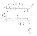
- fig. 2 is a plan view of the sheet 1 in a state folded along a fold edge 51
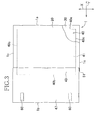
- Fig. 3 is a plan view of the sheet 1 in a state unfolded
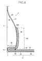
- Fig. 4 is a sectional view taken along line IV-IV in Fig. 1 .
- the sheet 1 has a longitudinal direction Y and a transverse direction X and is contoured by front and rear end edges 1a, 1b extending in the transverse direction X and a pair of side edges 1c extending in the longitudinal direction Y.
- the sheet 1 includes a liquid-permeable topsheet 20, a liquid-impermeable backsheet 30 and a liquid-absorbent structure 40 interposed between the sheets 20, 30.
- the topsheet 20 and the backsheet 30 are the same in size as well as in shape and are approximately rectangular.
- the absorbent structure 40 is contoured by front and rear end edges 40a, 40b extending in the transverse direction X and a pair of side edges 40c extending in the longitudinal direction Y.
- the absorbent structure 40 is dimensioned to be smaller than the topsheet 20 as well as the backsheet 30 and the topsheet 20 and the backsheet 30 are secured to each other outboard of the absorbent structure 40 by a joining means (not shown) such as a hot melt adhesive.
- the topsheet 20 may be formed of a known fibrous nonwoven fabric, for example, a thermally bonded fibrous nonwoven fabric.
- the backsheet 30 may be formed of, for example, a polyolefin-based plastic sheet or a laminate composed of such a plastic sheet and a nonwoven fabric.
- the sheet 1 is folded and two layers of the topsheet 20 facing each other are secured together along joining means 50 extending in the transverse direction X.
- the sheet 1 is formed with a fold edge 51 extending in the transverse direction X.
- the fold edge 51 is formed in a region of the sheet 1 including the absorbent structure 40.
- a hot melt adhesive may be used as the joining means 50.
- the absorbent structure 40 includes absorbent core material 44, a wrapping sheet 45 and a leakage barrier sheet 46 interposed between the wrapping sheet 45 and the backsheet 30.
- absorbent core material 44 wood fluff pulp, superabsorbent polymer particles or a mixture thereof may be used.
- wrapping sheet 45 for example, tissue paper may be used.
- leakage barrier sheet 46 a liquid-impermeable plastic film may be used.
- the absorbent structure 40 may be sectionalized into a first absorbent section 41, a second absorbent section 42 and a third absorbent section 43 lined up from the front end edge 1a toward the rear end edge 1b of the sheet 1.
- these first absorbent section 41 through the third absorbent section 43 are continuous to one to another in the longitudinal direction Y and the absorbent core material 44 forming these sections are not divided one from another.
- the first absorbent section 41 is defined by a region extending from a front end edge 40a of the absorbent structure 40 to the fold edge 51
- the second absorbent section 42 is defined by a region extending from the fold edge 51 to the joining means 50
- the third absorbent section 43 is defined by a region extending from the joining means 50 to a rear end edge 40b of the absorbent structure 40.
- the joining means 50 is provided between the second and third absorbent sections 42, 43 and the portion of the topsheet 20 lying in the first absorbent section 41 faces the portions of the topsheet 20 lying the second and third absorbent sections 42, 43 so as to bond these portions along the joining means 50
- the second absorbent section 42 is layered on the first absorbent section 41 in the thickness direction so that the respective portions of the topsheet in these first and second absorbent sections 41, 42 may face each other.
- the sheet 1 is formed outboard of the third absorbent section 43 in the longitudinal direction Y with a non-absorbent region 47 in which the absorbent structure 40 does not exist.
- this non-absorbent region 47 the topsheet 20 and the backsheet 30 are joined to each other with, for example, a hot melt adhesive.
- the backsheet 30 is provided with attachments 60.
- pressure-sensitive adhesive tapes may be used as the attachments 60 and the adhesive tapes may be folded inwardly so that the adhesive surface thereof might not be exposed before actual use. In actual use, the adhesive surface may be exposed and attached to the wall 71 so that the third absorbent section 43 and the non-absorbent region 47 may be retained to the wall 71.
- the third absorbent section 43 and the non-absorbent region 47 may be folded upward around the joining means 50 so as to be raised from the first absorbent section 41.
- the third absorbent section 43 and the non-absorbent region 47 raised in this manner may be placed so as to extend along the wall and may be secured to the wall 71 with use of the attachments 60.
- the second absorbent section 42 extends from the third absorbent section 43 to the wall 71.
- the backsheet 30 faces the floor 72 and the wall 71 while the topsheet 20 is exposed on the opposite side.
- An excess amount of the urine beyond the absorbent capacity of the third absorbent section 43 transfers further downwards to the side of the floor 72 and is absorbed by the second absorbent section 42 which is contiguous to the third absorbent section 43.
- An excess amount of the urine beyond the absorbent capacity of the second absorbent section 42 further transfers to the first absorbent section 41 and is absorbed by this section 41.
- the second absorbent section 42 of the absorbent structure 40 advantageously functions to reduce the amount of urine which transfer to the first absorbent section 41 compared to if the absorbent structure 40 is not disposed with the second absorbent section 42. If the first absorbent section 41 laid on the floor 72 is soiled with excrement such as urine over its wide range, there is a possibility that the pet animal might step thereon and that the urine might leak out of this first absorbent section 41. However, due to the provision of the second absorbent section 42, the area of the first absorbent section 41 which might be soiled may be reduced, thereby eliminating such inconvenience.
- the urine transferring from the third absorbent section 43 can be absorbed by the second absorbent section 42 placed more closely to the wall 71 than the third absorbent section 43.
- the second absorbent section 42 placed close to the wall 71 assures to retain the urine at a distance from the pet animal, thereby preventing the pet animal from coming in contact with the urine retained by the second absorbent section 42.
- the second absorbent section 42 has a retention capability sufficient to inhibit urine diffusion in the first absorbent section 41 after a predetermined time has elapsed.
- At least the second and third absorbent section 42, 43 are preferable to have a water-retention capacity in a range of 500 to 4000 g/m 2 .
- the first - third absorbent sections 41 - 43 are formed of the same material and approximately the same water retention capacity is assured over the all absorbent sections. If the water retention capacity is lower than 500g/m 2 , it will be difficult for the second and third absorbent section 42, 43 to absorb the amount of urine beyond the capacity of these sections 42, 43 and the excess amount of urine will transfer to the first absorbent section 41 whereby urine will diffuse in the first absorbent section 41 over a wide range.
- Measurement of a water retention capacity was carried out on the absorbent structure 40 of the sheet 1 having absorbed 0.9% aqueous solution of NaCl. More specifically, the measurement was carried out by the following steps. First, an initial mass of the sheet 1 and an area of the absorbent structure were measured. Then, the sheet 1 was immersed in 20l of the aqueous solution of NaCl for 10 minutes in such a manner that the sheet 1 was entirely immersed in the aqueous solution of NaCl. After 10 minutes, the sheet 1 was taken out of the aqueous solution and left as it is for 10 minutes to be naturally dehydrated.
- the sheet 1 was doubled up with the topsheet 20 exposed outward and this doubled-up sheet 1 was hung from an approximately horizontal bar so that the sheet may stride over the bar along the fold edge and left indoors for 10 minutes.
- the sheet 1 was dehydrated by a dewatering equipment under a mass of 150 g for 90 seconds.
- the sheet 1 having been dehydrated in this manner was measured. Water retention capacity was calculated according to the following calculating formula: mass of the sheet after dehydrating step - initial mass of the sheet / area of the absorbent structure ⁇ 100
- a length dimension in the longitudinal direction Y of the third absorbent section 43 is preferable in a region of about 20 mm to about 100 mm. If this length dimension is smaller than 20 mm, the amount of urine to be absorbed by the third absorbent section 43 would be inhibited and the excess amount of urine might transfer not to the second absorbent section 42 but directly to the first absorbent section 41. In such a case, the urine having transferred directly to the first absorbent section 41 might diffuse over a wide region of this first absorbent section 41. In contrast, if the length dimension is larger than 100 mm, the absorbed amount of urine would be increased and the mass of the third absorbent section 43 would correspondingly increase. Eventually, the attachments 60 might be peeled off the wall 71 and/or the third absorbent section 43 might collapse from the standing position.
- a length dimension in the longitudinal direction Y of the second absorbent section 42 is preferable in a range of about 10 mm to about 50 mm. If this length dimension is smaller than 10 mm, a water retention capacity of the second absorbent section 42 would unacceptably decrease and an amount of urine transferring to the first absorbent section 41 will correspondingly increase. In contrast, if the length dimension is larger than 50 mm, a range extending from the third absorbent section 43 to the wall 71 would be unacceptably enlarged and the joining means 50 above which the third absorbent section 43 stands up will be unacceptably distanced from the wall 71.
- the joining means 50 is unacceptably distanced from the wall 71, the pet animal, for example, a dog might step on the third absorbent section 43 normally in a upstanding posture and eventually the attachments 60 might be peeled off the wall 71.
- the water retention capacity of the second absorbent section 42 depends also upon the type and the amount of the absorbent core material and the above-mentioned length dimension may be sometimes determined in consideration of the water retention capacity.
- the third absorbent section 43 is formed with the non-absorbent region 47 in which the absorbent structure is not disposed.
- the non-absorbent region 47 approximately has no urine retention capacity and functions, particularly in an upper portion in the upstanding section of the sheet 1, to prevent the sheet 1 from becoming heavy due to the urine. If the portion of the sheet 1 in the upstanding posture becomes heavy, the attachments 60 might be peeled off the wall 71. However, the provision of the non-absorbent region makes it possible to prevent the attachments 60 from being peeled off, thereby preventing the portion of the sheet 1 in the upstanding posture from collapsing.
- the sheet 1 as a sample of the embodiment included a first absorbent section 41, a second absorbent section 42 and a third absorbent section 43 formed in a continuous manner.
- a length dimension in the longitudinal direction Y of the second absorbent section 42 was about 20 mm and a length dimension in the longitudinal direction Y of the third absorbent section 43 was about 40 mm.
- a sample of the comparative example 2 lacked the third absorbent section but was similar to the embodiment of the present invention in other aspects.
- a sample of the comparative example 3 lacked the second absorbent section but was similar to the embodiment of the present invention in other aspects.
- Each of the samples was put in a posture standing on the joining means 50 serving as the base point and attached to the wall by the attachments 60.
- a tilt angle of the sheet relative to the wall was set to about 4°.
- 40 ml of 0. 90 % aqueous solution of NaCL was dropped to the respective samples with use of a syringe (needleless Terumo syringe of 50 ml capacity). More specifically, aqueous solution of NaCl was dropped, spending about 10 seconds, from a point 10 mm above the topsheet almost vertically to the topsheet.
- An amount of the aqueous solution which had transferred along the surface of the topsheet toward the first absorbent section 41 after the dropping of the aqueous solution had started was determined as a liquid transfer length and an amount of the aqueous solution which had transferred to the first absorbent section 41 10 seconds after the dropping of the aqueous solution was determined as a liquid diffusion length after 10 seconds and an amount of the aqueous solution which had transferred to the first absorbent section 41 after the dropping of the aqueous solution had started was determined as a liquid diffusion length after 1 minute.
- the liquid transfer length was measured by visually confirming the liquid having transferred through the topsheet 20 and by measuring a transfer length from the joining means to the most remote attained point on the side of the front end edge 1a of the sheet 1.
- the liquid transfer length, the diffusion length after 10 seconds and the diffusion length after 1 minute suggest that the solution diffuses over significantly wider ranges of the first absorbent section 41 in comparison to the result measured for the embodiment of the present invention (Example in TABLE 1).
- the embodiment in which the second absorbent section and the third absorbent section were not integral with each other and the embodiment in which the first absorbent section and the second absorbent section were not integral with each other approximately the same result was obtained and the solution diffusion into the first absorbent section was more reliably inhibited than in the comparative examples 1 through 3.
- Fig. 5 is a sectional view similar to Fig. 4 and illustrates a second embodiment of the present invention.
- the second absorbent section 42 and the third absorbent section 43 are separated from each other in the longitudinal direction Y so far as the absorbent core material 44 contained in these sections 42, 43 is concerned.
- the second absorbent section 42 and the third absorbent section 43 respectively include the absorbent core material 44 wrapped with separate wrapping sheets 45 and, in consequence, these second and third absorbent sections 42, 43 are not functionally continuous with each other in the longitudinal direction Y.
- the other components are arranged in the same manner as in the first embodiment.
- the components similar to those in the first embodiment are designated with the same reference numerals used for the first embodiment and these components will not be repetitively described.
- the topsheet 20 and the backsheet 30 are directly bonded to each other between the second and third absorbent sections 42, 43 so as to segment the second and third absorbent sections 42, 43.
- the joining means 50 is provided in an absorbent core material-free region defined between the second and third absorbent sections 20, 30, namely, a region in which the topsheet 20 and the backsheet 30 are directly bonded to each other.
- the first absorbent section 41 and the second absorbent section 42 are continuously and integrally formed.
- the second and third absorbent sections 42, 43 By forming the second and third absorbent sections 42, 43 so that the absorbent core material 44 contained therein are neither continuous nor integral, a differential stiffness is generated between the core-free region and the core containing regions on both sides of the core-free region and the differential stiffness facilitates the sheet 1 to be easily folded around this core-free region.
- this core-free region facilitates the third absorbent section 43 to be upstanding and facilitates the third absorbent section 43 and the non-absorbent region 47 to be attached to the wall 71.
- the joining means 50 formed between the second and third absorbent sections 42, 43 further increase a differential stiffness between the joining means 50 and the core containing regions and such differential stiffness facilitates the third absorbent section 43 to be folded relative to the first absorbent section 41 and thereby facilitates the third absorbent section to be upstanding.
- a length dimension by which the absorbent core material in the second absorbent section 42 is spaced from the absorbent core material in the third absorbent section 43 is about 10 mm or less. If the length dimension exceeds this limit, there is a possibility that the urine transfer from the third absorbent section 43 to the second absorbent section 42 might be held off.
- Fig. 6 is a sectional view similar to Fig. 4 and illustrates a third embodiment of the present invention.
- the first absorbent section 41 and the second absorbent section 42 are separately formed.
- the other components are arranged in the same manner as in the first embodiment.
- the components similar to those in the first embodiment are designated with the same reference numerals used for the first embodiment and these components will not be repetitively described.
- the topsheet 20 and the backsheet 30 are bonded to each other through the leakage barrier sheet 46.
- the first absorbent section 41 and the second absorbent section 42 from each other in this manner, it is possible to fold the sheet 1 easily along this delimiting region and thereby to form the fold edge 51 easily. In this way, the sheet 1 may be easily folded on itself without losing its configuration and a packaging work may be facilitated.
- the second absorbent section 42 and the third absorbent section 43 are continuously and integrally formed.
- Fig. 7 is a sectional view similar to Fig. 4 and illustrates a fourth embodiment of the present invention.
- the first absorbent section 41 and the second absorbent section 42 are separated from each other in the longitudinal direction Y so far as the absorbent core material 44 contained in these sections 41, 42 is concerned and the topsheet and the backsheet covering these sections 41, 42 also are separated from each other in the longitudinal direction Y.
- the sheet 1 includes a first topsheet 20a and a first backsheet 30a cooperating with each other to wrap the first absorbent section 41 and a second topsheet 20a and a second backsheet 30b cooperating with each other to wrap the second and third absorbent sections 42, 43.
- the other components are arranged in the same manner as in the first embodiment.
- the components similar to those in the first embodiment are designated with the same reference numerals used for the first embodiment and these components will not be repetitively described.
- the first and second topsheets 20a, 20b are bonded to each other on the respective outer sides of the first and second topsheets 20a, 20b by joining means 52 extending in the transverse direction X. In consequence, no fold edge is formed between the first and second absorbent sections 41, 42. Provision of the joining means 52 makes it possible to prevent the animal excrement, for example, urine from leaking out from the first and second absorbent sections 41, 42 toward the wall 71.
- first and second absorbent sections 41, 42 have been described so as to be separated from each other in a thickness direction according to the present invention including the embodiments as have been described above, it is possible to arrange these absorbent sections 41, 42 integrally. Specifically, for example, it is possible to wrap the absorbent core material contained in the first and second absorbent sections 41, 42 with a common wrapping sheet and/or to arrange in a manner that the topsheet 20 is not present between the first and second absorbent sections 41, 42.
- first absorbent section 41 has been described so as to extend to a position under the second absorbent section 42 at which the first absorbent section 41 and the second absorbent section 42 are layered one upon another in the thickness direction so that the topsheet 20 may face itself, it is not essential for the present invention to layer the first absorbent section 41 and the second absorbent section 42 one upon another.
- the first absorbent section 41 may have a length dimension extending from the from the front end edge 40a to the joining means 50 and not extending beyond the joining means 50 toward the fold edge 51.
- the second absorbent section 42 is preferably layered on the first absorbent section 41 in the thickness direction of the first absorbent section 41 in order to enlarge an area over which the first absorbent section 41 and the second absorbent section 42 kept in contact with each other and thereby to retain the second absorbent section 42 stably. Furthermore, with such arrangement, an excess amount of urine beyond the capacity of the second absorbent section 42 may be rapidly absorbed by the first absorbent section 41 and whereby leakage of urine may be prevented.
- the absorbent sheet 1 according to the present invention lies in that: the absorbent structure 40 includes the first absorbent section 41, the second absorbent section 42 and the third absorbent section 43 arranged in the longitudinal direction Y; and the portion of the topsheet 20 extending between the second absorbent section 42 and the third absorbent section 43 and the portion of the topsheet 20 extending along the first absorbent section 41 are bonded to each other by the joining means 50.
- the constituent elements of the sheet 1 are not limited to those types of materials described in the specification but the other various types of materials widely used in the relevant technical field may be used without limitation unless otherwise stated.
- the terms “first”, “second” and “third” used in the specification of the present invention are used merely to distinguish the similar elements, similar positions or the other similar means.
Landscapes
- Life Sciences & Earth Sciences (AREA)
- Environmental Sciences (AREA)
- Zoology (AREA)
- Animal Husbandry (AREA)
- Biodiversity & Conservation Biology (AREA)
- Absorbent Articles And Supports Therefor (AREA)
- Housing For Livestock And Birds (AREA)
- Orthopedics, Nursing, And Contraception (AREA)
Abstract
Description
- The present invention relates to absorbent sheets and more particularly to absorbent sheets used to absorb bodily fluids, for example, urine discharged by pet animals.
- Conventionally, absorbent sheets used for pet animals are known. For example,
Patent Literature 1 discloses an absorbent sheet including a liquid-permeable topsheet, a liquid-impermeable backsheet and an absorbent core interposed between these sheets. This known absorbent sheet includes a flap in which the absorbent core does not exist and a region in which the absorbent core exists therein so that the region in which the absorbent core exists may be laid on the floor and the flap may be attached to the wall in use. Patent Literature 2 discloses an absorbent sheet including a water-absorbent structure and a lining vinyl-cover. In this known absorbent sheet, the water-absorbent structure is formed with a fold extending to bisect the sheet into two sections so that one of these two sections may be attached to the floor and the other section may be attached to the wall in use. In this way, it is possible for the section attached to the wall to prevent the wall from being soiled with urine even when a male dog voids against the wall. -
- {PTL 1}:
JP 2001-8568 A - {PTL 2}:
JP 63-178451 U - However, in the absorbent sheets disclosed in
Patent Literatures 1 and 2, there is a possibility that urine discharged against the section of the sheet attached to the wall might transfer downward to the section laid on the floor, diffuse in this section over a wide range and soil this section beyond the acceptability area. - An object of the present invention is to provide an absorbent sheet being capable of inhibiting urine from diffusing in the section of the sheet laid on the floor.
- The present invention provides an absorbent sheet having a longitudinal direction and a transverse direction and including a liquid-permeable topsheet, a liquid-impermeable backsheet and an absorbent structure interposed between these sheets. The absorbent structure includes a first absorbent section, a second absorbent section and a third absorbent section arranged in the longitudinal direction. A portion of the topsheet extending between the second absorbent section and the third absorbent section and a portion of the topsheet extending along the first absorbent section are secured to each other by a joining means.
- With the absorbent sheet according to one or more embodiments of the present invention, in the first absorbent section, the second absorbent section and the third absorbent section arranged in the longitudinal direction, the first absorbent section and the second absorbent section are secured to each other by the joining means through the portions of the topsheet extending in the respective absorbent sections. When the third absorbent section is put in the upstanding posture relative to the first absorbent section, the second absorbent section extends from the third absorbent section so that the liquid such as urine once having been absorbed by the third absorbent section may be absorbed by the second absorbent section and transfer of a liquid to the first absorbent section may be inhibited.
-
- {
Fig. 1} Fig. 1 is a perspective view illustrating an example of a manner of utilization of an absorbent sheet according to a first embodiment of the present invention. - {
Fig. 2} Fig. 2 is a plan view of the absorbent sheet. - {
Fig. 3} Fig. 3 is also a plan view of the absorbent sheet. - {
Fig. 4} Fig. 4 is a sectional view taken along line IV-IV inFig. 1 . - {
Fig. 5} Fig. 5 is a sectional view of the absorbent sheet according to a second embodiment. - {
Fig. 6} Fig. 6 is a sectional view of the absorbent sheet according to a third embodiment. - {
Fig. 7} Fig. 7 is a sectional view of the absorbent sheet according to a fourth embodiment. -
Figs. 1 through 4 illustrate a first embodiment of an absorbent sheet according to the present invention.
Fig. 1 is a perspective view illustrating a manner of utilizing thesheet 1,fig. 2 is a plan view of thesheet 1 in a state folded along afold edge 51,Fig. 3 is a plan view of thesheet 1 in a state unfolded andFig. 4 is a sectional view taken along line IV-IV inFig. 1 . - Referring to
Figs. 1 through 4 , thesheet 1 has a longitudinal direction Y and a transverse direction X and is contoured by front andrear end edges side edges 1c extending in the longitudinal direction Y. Thesheet 1 includes a liquid-permeable topsheet 20, a liquid-impermeable backsheet 30 and a liquid-absorbent structure 40 interposed between thesheets topsheet 20 and thebacksheet 30 are the same in size as well as in shape and are approximately rectangular. - The
absorbent structure 40 is contoured by front andrear end edges side edges 40c extending in the longitudinal direction Y. Theabsorbent structure 40 is dimensioned to be smaller than thetopsheet 20 as well as thebacksheet 30 and thetopsheet 20 and thebacksheet 30 are secured to each other outboard of theabsorbent structure 40 by a joining means (not shown) such as a hot melt adhesive. Thetopsheet 20 may be formed of a known fibrous nonwoven fabric, for example, a thermally bonded fibrous nonwoven fabric. Thebacksheet 30 may be formed of, for example, a polyolefin-based plastic sheet or a laminate composed of such a plastic sheet and a nonwoven fabric. - Referring to
Fig. 2 , thesheet 1 is folded and two layers of thetopsheet 20 facing each other are secured together along joiningmeans 50 extending in the transverse direction X. In consequence, thesheet 1 is formed with afold edge 51 extending in the transverse direction X. Thefold edge 51 is formed in a region of thesheet 1 including theabsorbent structure 40. As the joining means 50, for example, a hot melt adhesive may be used. - Referring to
Fig. 4 , theabsorbent structure 40 includesabsorbent core material 44, awrapping sheet 45 and aleakage barrier sheet 46 interposed between thewrapping sheet 45 and thebacksheet 30. As theabsorbent core material 44, wood fluff pulp, superabsorbent polymer particles or a mixture thereof may be used. As thewrapping sheet 45, for example, tissue paper may be used. As theleakage barrier sheet 46, a liquid-impermeable plastic film may be used. - The
absorbent structure 40 may be sectionalized into a firstabsorbent section 41, a secondabsorbent section 42 and a thirdabsorbent section 43 lined up from thefront end edge 1a toward therear end edge 1b of thesheet 1. In this regard, these firstabsorbent section 41 through the thirdabsorbent section 43 are continuous to one to another in the longitudinal direction Y and theabsorbent core material 44 forming these sections are not divided one from another. Specifically, the firstabsorbent section 41 is defined by a region extending from afront end edge 40a of theabsorbent structure 40 to thefold edge 51, the secondabsorbent section 42 is defined by a region extending from thefold edge 51 to thejoining means 50 and the thirdabsorbent section 43 is defined by a region extending from the joining means 50 to arear end edge 40b of theabsorbent structure 40. In this way, thejoining means 50 is provided between the second and thirdabsorbent sections topsheet 20 lying in the firstabsorbent section 41 faces the portions of thetopsheet 20 lying the second and thirdabsorbent sections joining means 50 The secondabsorbent section 42 is layered on the firstabsorbent section 41 in the thickness direction so that the respective portions of the topsheet in these first and secondabsorbent sections - The
sheet 1 is formed outboard of the thirdabsorbent section 43 in the longitudinal direction Y with anon-absorbent region 47 in which theabsorbent structure 40 does not exist. In thisnon-absorbent region 47, thetopsheet 20 and thebacksheet 30 are joined to each other with, for example, a hot melt adhesive. - In the
non-absorbent region 47 of thesheet 1, thebacksheet 30 is provided withattachments 60. Specifically, pressure-sensitive adhesive tapes may be used as theattachments 60 and the adhesive tapes may be folded inwardly so that the adhesive surface thereof might not be exposed before actual use. In actual use, the adhesive surface may be exposed and attached to thewall 71 so that the thirdabsorbent section 43 and thenon-absorbent region 47 may be retained to thewall 71. - When the
sheet 1 described above is actually used, after the firstabsorbent section 72 has been laid on thefloor 72, the thirdabsorbent section 43 and thenon-absorbent region 47 may be folded upward around thejoining means 50 so as to be raised from the firstabsorbent section 41. The thirdabsorbent section 43 and thenon-absorbent region 47 raised in this manner may be placed so as to extend along the wall and may be secured to thewall 71 with use of theattachments 60. In this state, the secondabsorbent section 42 extends from the thirdabsorbent section 43 to thewall 71. In the same state, thebacksheet 30 faces thefloor 72 and thewall 71 while thetopsheet 20 is exposed on the opposite side. Even if the pet animal discharges urine against thesheet 1 set in this manner, it is possible to prevent the urine from spattering on thewall 71 since thewall 71 is protectively covered with thenon-absorbent region 47 and the thirdabsorbent section 43 of thesheet 1. Particularly a male dog has a habit of lifting his one paw to discharge urine against a relatively high target and, even in such a case, thesheet 1 partially covering thewall 71 prevents thewall 71 from being soiled with the discharged urine. The urine discharged against thenon-absorbent region 47 transfers downward to the thirdabsorbent section 43 and absorbed by the portion of theabsorbent core material 44 contained within this thirdabsorbent section 43. An excess amount of the urine beyond the absorbent capacity of the thirdabsorbent section 43 transfers further downwards to the side of thefloor 72 and is absorbed by the secondabsorbent section 42 which is contiguous to the thirdabsorbent section 43. An excess amount of the urine beyond the absorbent capacity of the secondabsorbent section 42 further transfers to the firstabsorbent section 41 and is absorbed by thissection 41. - The second
absorbent section 42 of theabsorbent structure 40 advantageously functions to reduce the amount of urine which transfer to the firstabsorbent section 41 compared to if theabsorbent structure 40 is not disposed with the secondabsorbent section 42. If the firstabsorbent section 41 laid on thefloor 72 is soiled with excrement such as urine over its wide range, there is a possibility that the pet animal might step thereon and that the urine might leak out of this firstabsorbent section 41. However, due to the provision of the secondabsorbent section 42, the area of the firstabsorbent section 41 which might be soiled may be reduced, thereby eliminating such inconvenience. - According to this embodiment, the urine transferring from the third
absorbent section 43 can be absorbed by the secondabsorbent section 42 placed more closely to thewall 71 than the thirdabsorbent section 43. Considering the habit of the pet animal discharging urine from the position on the side of thetopsheet 20 against thewall 71, the secondabsorbent section 42 placed close to thewall 71 assures to retain the urine at a distance from the pet animal, thereby preventing the pet animal from coming in contact with the urine retained by the secondabsorbent section 42. - In addition, the second
absorbent section 42 has a retention capability sufficient to inhibit urine diffusion in the firstabsorbent section 41 after a predetermined time has elapsed. - At least the second and third
absorbent section absorbent section sections absorbent section 41 whereby urine will diffuse in the firstabsorbent section 41 over a wide range. Though it is possible to enhance the water retention capacity and thereby to reduce the amount of urine transferring to the firstabsorbent section 41 but such countermeasure will often increase an amount of the absorbent core material leading to a thickabsorbent structure 40. If the water retention capacity exceeds 4000g/m2, the second and thirdabsorbent sections attachments 60 might be peeled off thewall 71 and/or the thirdabsorbent section 43 in its upstanding posture might collapse. - Measurement of a water retention capacity was carried out on the
absorbent structure 40 of thesheet 1 having absorbed 0.9% aqueous solution of NaCl. More specifically, the measurement was carried out by the following steps. First, an initial mass of thesheet 1 and an area of the absorbent structure were measured. Then, thesheet 1 was immersed in 20ℓ of the aqueous solution of NaCl for 10 minutes in such a manner that thesheet 1 was entirely immersed in the aqueous solution of NaCl. After 10 minutes, thesheet 1 was taken out of the aqueous solution and left as it is for 10 minutes to be naturally dehydrated. More specifically, thesheet 1 was doubled up with thetopsheet 20 exposed outward and this doubled-upsheet 1 was hung from an approximately horizontal bar so that the sheet may stride over the bar along the fold edge and left indoors for 10 minutes. Thesheet 1 was dehydrated by a dewatering equipment under a mass of 150 g for 90 seconds. Thesheet 1 having been dehydrated in this manner was measured. Water retention capacity was calculated according to the following calculating formula:
- A length dimension in the longitudinal direction Y of the third
absorbent section 43 is preferable in a region of about 20 mm to about 100 mm. If this length dimension is smaller than 20 mm, the amount of urine to be absorbed by the thirdabsorbent section 43 would be inhibited and the excess amount of urine might transfer not to the secondabsorbent section 42 but directly to the firstabsorbent section 41. In such a case, the urine having transferred directly to the firstabsorbent section 41 might diffuse over a wide region of this firstabsorbent section 41. In contrast, if the length dimension is larger than 100 mm, the absorbed amount of urine would be increased and the mass of the thirdabsorbent section 43 would correspondingly increase. Eventually, theattachments 60 might be peeled off thewall 71 and/or the thirdabsorbent section 43 might collapse from the standing position. - A length dimension in the longitudinal direction Y of the second
absorbent section 42 is preferable in a range of about 10 mm to about 50 mm. If this length dimension is smaller than 10 mm, a water retention capacity of the secondabsorbent section 42 would unacceptably decrease and an amount of urine transferring to the firstabsorbent section 41 will correspondingly increase. In contrast, if the length dimension is larger than 50 mm, a range extending from the thirdabsorbent section 43 to thewall 71 would be unacceptably enlarged and the joining means 50 above which the thirdabsorbent section 43 stands up will be unacceptably distanced from thewall 71. If the joiningmeans 50 is unacceptably distanced from thewall 71, the pet animal, for example, a dog might step on the thirdabsorbent section 43 normally in a upstanding posture and eventually theattachments 60 might be peeled off thewall 71. In this regard, the water retention capacity of the secondabsorbent section 42 depends also upon the type and the amount of the absorbent core material and the above-mentioned length dimension may be sometimes determined in consideration of the water retention capacity. - The third
absorbent section 43 is formed with thenon-absorbent region 47 in which the absorbent structure is not disposed. Thenon-absorbent region 47 approximately has no urine retention capacity and functions, particularly in an upper portion in the upstanding section of thesheet 1, to prevent thesheet 1 from becoming heavy due to the urine. If the portion of thesheet 1 in the upstanding posture becomes heavy, theattachments 60 might be peeled off thewall 71. However, the provision of the non-absorbent region makes it possible to prevent theattachments 60 from being peeled off, thereby preventing the portion of thesheet 1 in the upstanding posture from collapsing. - The inventors conducted a series of confirmatory test for liquid diffusivity on an embodiment of the present invention and comparative examples. The
sheet 1 as a sample of the embodiment included a firstabsorbent section 41, a secondabsorbent section 42 and a thirdabsorbent section 43 formed in a continuous manner. A length dimension in the longitudinal direction Y of the secondabsorbent section 42 was about 20 mm and a length dimension in the longitudinal direction Y of the thirdabsorbent section 43 was about 40 mm. A sample of the comparative example 1 included neither the second absorbent section nor the third absorbent section. In other words, the comparative example 1 only included the first absorbent section but similar to the embodiment of the present invention in other aspects. A sample of the comparative example 2 lacked the third absorbent section but was similar to the embodiment of the present invention in other aspects. A sample of the comparative example 3 lacked the second absorbent section but was similar to the embodiment of the present invention in other aspects. - Each of the samples was put in a posture standing on the joining means 50 serving as the base point and attached to the wall by the
attachments 60. A tilt angle of the sheet relative to the wall was set to about 4°. At a position 200 mm distanced from the joining means 50 toward thenon-absorbent region point 10 mm above the topsheet almost vertically to the topsheet. - An amount of the aqueous solution which had transferred along the surface of the topsheet toward the first
absorbent section 41 after the dropping of the aqueous solution had started was determined as a liquid transfer length and an amount of the aqueous solution which had transferred to the firstabsorbent section 41 10 seconds after the dropping of the aqueous solution was determined as a liquid diffusion length after 10 seconds and an amount of the aqueous solution which had transferred to the firstabsorbent section 41 after the dropping of the aqueous solution had started was determined as a liquid diffusion length after 1 minute. The liquid transfer length was measured by visually confirming the liquid having transferred through thetopsheet 20 and by measuring a transfer length from the joining means to the most remote attained point on the side of thefront end edge 1a of thesheet 1. With respect to the diffusion length after 10 seconds and the diffusion length after 1 minute, the solution transferring to the firstabsorbent section 41 were visually confirmed through thetopsheet 20 and the respective diffusion lengths from the joining means to the respective most remote points on thefront end edge 1a were measured. Such measurements were conducted three times and respective average values were calculated.[TABLE 1] Example Comparative example 1 Comparative example 2 Comparative example 3 Liquid transfer length 15 mm 70 mm 70 mm 50 mm Diffusion length after 10 sec 64 mm 100 mm 100 mm 85 mm Diffusion length after 1 min 75 mm 136 mm 132 mm 108 mm - Referring to TABLE 1, in all the comparative examples 1 through 3, the liquid transfer length, the diffusion length after 10 seconds and the diffusion length after 1 minute suggest that the solution diffuses over significantly wider ranges of the first
absorbent section 41 in comparison to the result measured for the embodiment of the present invention (Example in TABLE 1). In this regard, though not indicated in TABLE 1, from the similar test conducted to the other two embodiments of the present invention, i.e., the embodiment in which the second absorbent section and the third absorbent section were not integral with each other and the embodiment in which the first absorbent section and the second absorbent section were not integral with each other, approximately the same result was obtained and the solution diffusion into the first absorbent section was more reliably inhibited than in the comparative examples 1 through 3. -
Fig. 5 is a sectional view similar toFig. 4 and illustrates a second embodiment of the present invention. As illustrated, according to this embodiment, the secondabsorbent section 42 and the thirdabsorbent section 43 are separated from each other in the longitudinal direction Y so far as theabsorbent core material 44 contained in thesesections absorbent section 42 and the thirdabsorbent section 43 respectively include theabsorbent core material 44 wrapped withseparate wrapping sheets 45 and, in consequence, these second and thirdabsorbent sections - According to this second embodiment, the
topsheet 20 and thebacksheet 30 are directly bonded to each other between the second and thirdabsorbent sections absorbent sections absorbent sections topsheet 20 and thebacksheet 30 are directly bonded to each other. The firstabsorbent section 41 and the secondabsorbent section 42 are continuously and integrally formed. - By forming the second and third
absorbent sections absorbent core material 44 contained therein are neither continuous nor integral, a differential stiffness is generated between the core-free region and the core containing regions on both sides of the core-free region and the differential stiffness facilitates thesheet 1 to be easily folded around this core-free region. In consequence, this core-free region facilitates the thirdabsorbent section 43 to be upstanding and facilitates the thirdabsorbent section 43 and thenon-absorbent region 47 to be attached to thewall 71. Furthermore, the joining means 50 formed between the second and thirdabsorbent sections means 50 and the core containing regions and such differential stiffness facilitates the thirdabsorbent section 43 to be folded relative to the firstabsorbent section 41 and thereby facilitates the third absorbent section to be upstanding. - As a result of delimiting the second and third
absorbent sections absorbent section 43 does not directly transfer to the secondabsorbent section 42. However, the urine may transfer to the secondabsorbent section 42 along thetopsheet 20. Consequently, it is possible to decrease the amount of urine which otherwise might transfer to the firstabsorbent section 41. Preferably, a length dimension by which the absorbent core material in the secondabsorbent section 42 is spaced from the absorbent core material in the thirdabsorbent section 43 is about 10 mm or less. If the length dimension exceeds this limit, there is a possibility that the urine transfer from the thirdabsorbent section 43 to the secondabsorbent section 42 might be held off. -
Fig. 6 is a sectional view similar toFig. 4 and illustrates a third embodiment of the present invention. According to this embodiment, the firstabsorbent section 41 and the secondabsorbent section 42 are separately formed. The other components are arranged in the same manner as in the first embodiment. The components similar to those in the first embodiment are designated with the same reference numerals used for the first embodiment and these components will not be repetitively described. - According to this third embodiment, in a region delimiting the first
absorbent section 41 and the secondabsorbent section 42 from each other, thetopsheet 20 and thebacksheet 30 are bonded to each other through theleakage barrier sheet 46. By delimiting the firstabsorbent section 41 and the secondabsorbent section 42 from each other in this manner, it is possible to fold thesheet 1 easily along this delimiting region and thereby to form thefold edge 51 easily. In this way, thesheet 1 may be easily folded on itself without losing its configuration and a packaging work may be facilitated. In this regard, the secondabsorbent section 42 and the thirdabsorbent section 43 are continuously and integrally formed. -
Fig. 7 is a sectional view similar toFig. 4 and illustrates a fourth embodiment of the present invention. According to this embodiment, the firstabsorbent section 41 and the secondabsorbent section 42 are separated from each other in the longitudinal direction Y so far as theabsorbent core material 44 contained in thesesections sections sheet 1 includes afirst topsheet 20a and afirst backsheet 30a cooperating with each other to wrap the firstabsorbent section 41 and asecond topsheet 20a and asecond backsheet 30b cooperating with each other to wrap the second and thirdabsorbent sections - The first and
second topsheets second topsheets means 52 extending in the transverse direction X. In consequence, no fold edge is formed between the first and secondabsorbent sections means 52 makes it possible to prevent the animal excrement, for example, urine from leaking out from the first and secondabsorbent sections wall 71. - While the first and second
absorbent sections absorbent sections absorbent sections topsheet 20 is not present between the first and secondabsorbent sections - While the first
absorbent section 41 has been described so as to extend to a position under the secondabsorbent section 42 at which the firstabsorbent section 41 and the secondabsorbent section 42 are layered one upon another in the thickness direction so that thetopsheet 20 may face itself, it is not essential for the present invention to layer the firstabsorbent section 41 and the secondabsorbent section 42 one upon another. For example, the firstabsorbent section 41 may have a length dimension extending from the from thefront end edge 40a to the joiningmeans 50 and not extending beyond the joining means 50 toward thefold edge 51. However, the secondabsorbent section 42 is preferably layered on the firstabsorbent section 41 in the thickness direction of the firstabsorbent section 41 in order to enlarge an area over which the firstabsorbent section 41 and the secondabsorbent section 42 kept in contact with each other and thereby to retain the secondabsorbent section 42 stably. Furthermore, with such arrangement, an excess amount of urine beyond the capacity of the secondabsorbent section 42 may be rapidly absorbed by the firstabsorbent section 41 and whereby leakage of urine may be prevented. - The disclosure of the present invention having been described hereinabove may be arranged as follows:
- The
absorbent sheet 1 has the longitudinal direction Y and the transverse direction X and includes the liquid-permeable topsheet 20, the liquid-impermeable backsheet 30 and theabsorbent structure 40 interposed between thesesheets - The
absorbent sheet 1 according to the present invention lies in that: theabsorbent structure 40 includes the firstabsorbent section 41, the secondabsorbent section 42 and the thirdabsorbent section 43 arranged in the longitudinal direction Y; and the portion of thetopsheet 20 extending between the secondabsorbent section 42 and the thirdabsorbent section 43 and the portion of thetopsheet 20 extending along the firstabsorbent section 41 are bonded to each other by the joiningmeans 50. - The present invention having been described hereinabove may at least include embodiments as described below:
- (1) The
fold edge 51 extending in the transverse direction X is formed between the firstabsorbent section 41 and the joiningmeans 50. - (2) The joining means 50 extends in the transverse direction X.
- (3) The
absorbent structure 40 further includes thenon-absorbent region 47 in which thetopsheet 20 and thebacksheet 30 are directly bonded to each other outboard of the thirdabsorbent section 43 in the longitudinal direction Y. - (4) The second
absorbent section 42 and the thirdabsorbent section 43 are formed so as to be continuous with each other. - (5) The first
absorbent section 41 and the secondabsorbent section 42 are formed so as to be continuous with each other. - (6) The second
absorbent section 42 is layered on the firstabsorbent section 41 in a thickness direction of the firstabsorbent section 41. - (7) The
backsheet 30 is provided in thenon-absorbent region 47 withattachments 60 adapted to attach the backsheet to anattachment object 71. - (8)The water retention capacity of the second and third
absorbent sections - (9) The third
absorbent section 43 has a length dimension in the longitudinal direction Y in a range of 20 to 100 min. - The constituent elements of the
sheet 1 are not limited to those types of materials described in the specification but the other various types of materials widely used in the relevant technical field may be used without limitation unless otherwise stated. The terms "first", "second" and "third" used in the specification of the present invention are used merely to distinguish the similar elements, similar positions or the other similar means. -
- 1
- absorbent sheet
- 20
- topsheet
- 20a
- first topsheet
- 20b
- second topsheet
- 30
- backsheet
- 30a
- first backsheet
- 30b
- second backsheet
- 40
- absorbent structure
- 40a
- front end edge
- 40b
- rear end edge
- 41
- first absorbent region
- 42
- second absorbent region
- 43
- third absorbent region
- 47
- non-absorbent region
- 50
- joining means
- 51
- fold edge
- 60
- attachments
- 71
- attachment object (wall)
- X
- transverse direction
- Y
- longitudinal direction
Claims (10)
- An absorbent sheet having a longitudinal direction and a transverse direction and including a liquid-permeable topsheet, a liquid-impermeable backsheet and an absorbent structure interposed between these sheets, wherein:the absorbent structure includes a first absorbent section, a second absorbent section and a third absorbent section arranged in the longitudinal direction; anda portion of the topsheet extending between the second absorbent section and the third absorbent section and a portion of the topsheet extending along the first absorbent section are joined to each other by a joining means.
- The absorbent sheet according to Claim 1, wherein a fold edge extending in the transverse direction is formed between the first absorbent section and the joining means.
- The absorbent sheet according to Claim 1, wherein the joining means extends in the transverse direction.
- The absorbent sheet according to Claim 1, wherein the absorbent structure further includes a non-absorbent region in which the topsheet and the backsheet are directly bonded to each other outboard of the third absorbent section in the longitudinal direction.
- The absorbent sheet according to Claim 1, wherein the second absorbent section and the third absorbent section are formed so as to be continuous with each other.
- The absorbent sheet according to Claim 1, wherein the first absorbent section and the second absorbent section are formed so as to be continuous with each other.
- The absorbent sheet according to Claim 1, wherein the second absorbent section is layered on the first absorbent section in a thickness direction of the first absorbent section.
- The absorbent sheet according to Claim 4, wherein the backsheet is provided in the non-absorbent region with attachments adapted to attach the backsheet to an attachment object.
- The absorbent sheet according to Claim 1, wherein a water retention capacity of the second and third absorbent sections is in a range of 500 to 4000 g/m2.
- The absorbent sheet according to Claim 1, wherein the third absorbent section has a length dimension in the longitudinal direction in a range of 20 to 100 mm.
Applications Claiming Priority (2)
| Application Number | Priority Date | Filing Date | Title |
|---|---|---|---|
| JP2011155218A JP5892738B2 (en) | 2011-07-13 | 2011-07-13 | Absorbent sheet |
| PCT/JP2012/062605 WO2013008533A1 (en) | 2011-07-13 | 2012-05-17 | Absorbent sheet |
Publications (3)
| Publication Number | Publication Date |
|---|---|
| EP2732697A1 true EP2732697A1 (en) | 2014-05-21 |
| EP2732697A4 EP2732697A4 (en) | 2015-03-25 |
| EP2732697B1 EP2732697B1 (en) | 2016-04-27 |
Family
ID=47505831
Family Applications (1)
| Application Number | Title | Priority Date | Filing Date |
|---|---|---|---|
| EP12811919.5A Not-in-force EP2732697B1 (en) | 2011-07-13 | 2012-05-17 | Absorbent sheet |
Country Status (5)
| Country | Link |
|---|---|
| US (1) | US10602715B2 (en) |
| EP (1) | EP2732697B1 (en) |
| JP (1) | JP5892738B2 (en) |
| CN (1) | CN103648269B (en) |
| WO (1) | WO2013008533A1 (en) |
Families Citing this family (8)
| Publication number | Priority date | Publication date | Assignee | Title |
|---|---|---|---|---|
| JP5808444B2 (en) * | 2014-02-14 | 2015-11-10 | ジェックス株式会社 | Rabbit sheets |
| JP6356578B2 (en) * | 2014-11-10 | 2018-07-11 | 花王株式会社 | Pet toilet |
| US9532546B1 (en) | 2015-09-23 | 2017-01-03 | Rocky & Maggie's Pet Products, Inc. | Urine pad with automatically deployed three dimensional target |
| JP6185042B2 (en) * | 2015-12-21 | 2017-08-23 | ユニ・チャーム株式会社 | Animal excrement disposal sheet |
| JP6075929B1 (en) * | 2016-11-16 | 2017-02-08 | 大前 英二 | Pet toilet seat |
| WO2019241874A1 (en) * | 2018-06-22 | 2019-12-26 | Courchesne Alain | Wetting wall device for pets |
| USD975940S1 (en) * | 2020-12-02 | 2023-01-17 | Brian J P Grant | Pet urine pad |
| USD1075177S1 (en) * | 2024-10-30 | 2025-05-13 | Jennifer Maria McCarthy | Pet food mat |
Family Cites Families (41)
| Publication number | Priority date | Publication date | Assignee | Title |
|---|---|---|---|---|
| US1964242A (en) * | 1933-01-03 | 1934-06-26 | Evr Klean Seat Pad Co | Seat cover |
| DE3708556C2 (en) * | 1986-03-21 | 1994-12-01 | Colgate Palmolive Co | Absorbent insert for animal tubs and. the like |
| JPH036205Y2 (en) * | 1987-04-22 | 1991-02-18 | ||
| JPS63178451U (en) | 1987-05-09 | 1988-11-18 | ||
| US4800677A (en) * | 1987-09-21 | 1989-01-31 | Colgate-Palmolive Company | Animal waste collection pad |
| US5080046A (en) * | 1989-10-16 | 1992-01-14 | Rudolph Cassone | Disposable canine lavatory |
| US5762642A (en) * | 1993-05-24 | 1998-06-09 | The Procter & Gamble Company | Absorbent article, particularly sanitary napkin |
| JP4580440B2 (en) * | 1999-04-26 | 2010-11-10 | ユニ・チャームペットケア株式会社 | Excrement absorption sheet |
| JP4205277B2 (en) * | 1999-04-26 | 2009-01-07 | ユニ・チャームペットケア株式会社 | Excrement absorption sheet and method for producing the same |
| JP4421075B2 (en) * | 2000-05-10 | 2010-02-24 | ユニ・チャームペットケア株式会社 | Pet seat |
| JP4363753B2 (en) * | 2000-06-28 | 2009-11-11 | ユニ・チャームペットケア株式会社 | Pet seat |
| JP3926587B2 (en) * | 2001-07-12 | 2007-06-06 | ユニ・チャーム株式会社 | Absorbent articles |
| JP3959339B2 (en) * | 2002-11-12 | 2007-08-15 | ユニ・チャーム株式会社 | Absorbent articles |
| JP3797981B2 (en) * | 2003-06-02 | 2006-07-19 | ユニ・チャームペットケア株式会社 | Pet seat |
| US7007635B2 (en) * | 2003-06-10 | 2006-03-07 | Kincaid Virginia E | Cat litter pods |
| JP2005323548A (en) * | 2004-05-14 | 2005-11-24 | Mitsubishi Chemicals Corp | Water absorbent composite sheet for pet sheets, method for producing the same and pet sheets |
| JP4231492B2 (en) * | 2004-06-02 | 2009-02-25 | 康仁 倉橋 | Pet toilets and replacement sheets |
| EP1758734B1 (en) * | 2004-06-18 | 2019-01-09 | Textronics, Inc. | Textile structures for heating or warming |
| US7249570B1 (en) * | 2004-11-29 | 2007-07-31 | Jermaine C Roberson | Disposable nonskid absorbent pad |
| US20060191488A1 (en) * | 2005-02-28 | 2006-08-31 | Stephen Ricchiuti | P-Pole |
| JP4652847B2 (en) * | 2005-03-01 | 2011-03-16 | ユニ・チャーム株式会社 | Method for producing excreta absorbent sheet for pet |
| JP4570481B2 (en) * | 2005-03-01 | 2010-10-27 | ユニ・チャームペットケア株式会社 | Pet excreta absorption sheet |
| US20060260559A1 (en) * | 2005-05-19 | 2006-11-23 | The Bramton Company | Multifunctional canine training pad |
| JP2009504347A (en) * | 2005-08-19 | 2009-02-05 | ザ プロクター アンド ギャンブル カンパニー | Absorbent articles |
| US8336497B2 (en) * | 2006-01-20 | 2012-12-25 | Van Zuilekom Linda Joy | Small animal toilet pad |
| US20070179468A1 (en) * | 2006-01-30 | 2007-08-02 | Labelle Jeffery | Pet urine pad with vertical target and absorbent base |
| US8142410B2 (en) * | 2006-09-14 | 2012-03-27 | Absorbest, Ab | Fluid absorption mat |
| JP2008199998A (en) * | 2007-02-22 | 2008-09-04 | Yukio Oishi | Liquid-absorbent sheet for pet and cage wall surface-engaging tool of the same |
| US20080223301A1 (en) * | 2007-03-12 | 2008-09-18 | Nagao Glenn S | Canine housebreaking device |
| US20080236504A1 (en) * | 2007-03-28 | 2008-10-02 | Stephen Silverman | Pet waste collection pad |
| US8080372B2 (en) | 2007-04-11 | 2011-12-20 | Canon Kabushiki Kaisha | Method for detecting nucleic acid in sample, method for designing probes, system for designing probes therefor |
| US7607732B2 (en) * | 2007-06-22 | 2009-10-27 | B/E Aerospace, Inc. | One-piece dress cover for aircraft seat |
| JP4235956B2 (en) * | 2008-06-24 | 2009-03-11 | 株式会社ホンダアクセス | Vehicle seat cover |
| JP5108727B2 (en) * | 2008-11-17 | 2012-12-26 | 花王株式会社 | Laminated sheet for pet excreta disposal |
| JP3156089U (en) * | 2009-04-07 | 2009-12-17 | 宏麗 大原 | Pet toilet eco-sheet |
| BRMU8900806U2 (en) * | 2009-04-29 | 2010-12-28 | Windustry Ind De Produtos Veterinarios Ltda | constructive arrangement introduced into flap mat for absorbing pet urine |
| JP2011045353A (en) * | 2009-08-28 | 2011-03-10 | Eiichi Ishida | Pet sheet |
| US8852717B2 (en) * | 2010-02-05 | 2014-10-07 | Gail Elizabeth Davis | Disposable mat and method for containing a spilled liquid |
| PL3287110T3 (en) * | 2011-06-10 | 2019-08-30 | The Procter And Gamble Company | Method of making absorbent structures for absorbent articles |
| US20140283752A1 (en) * | 2013-03-20 | 2014-09-25 | Nuguna Robin Lowe | Pad for waste collection and disposal |
| US20190239483A1 (en) * | 2018-02-07 | 2019-08-08 | Alex Thibault | Dog Urine Pad Assembly |
-
2011
- 2011-07-13 JP JP2011155218A patent/JP5892738B2/en active Active
-
2012
- 2012-05-17 EP EP12811919.5A patent/EP2732697B1/en not_active Not-in-force
- 2012-05-17 WO PCT/JP2012/062605 patent/WO2013008533A1/en not_active Ceased
- 2012-05-17 CN CN201280034513.3A patent/CN103648269B/en not_active Expired - Fee Related
- 2012-05-17 US US14/232,242 patent/US10602715B2/en active Active
Also Published As
| Publication number | Publication date |
|---|---|
| US10602715B2 (en) | 2020-03-31 |
| EP2732697B1 (en) | 2016-04-27 |
| EP2732697A4 (en) | 2015-03-25 |
| WO2013008533A1 (en) | 2013-01-17 |
| CN103648269A (en) | 2014-03-19 |
| CN103648269B (en) | 2016-03-16 |
| JP2013017448A (en) | 2013-01-31 |
| US20140137805A1 (en) | 2014-05-22 |
| JP5892738B2 (en) | 2016-03-23 |
Similar Documents
| Publication | Publication Date | Title |
|---|---|---|
| EP2732697B1 (en) | Absorbent sheet | |
| US11135104B2 (en) | Diaper product adapted for collection of exudate sample from an infant | |
| US10646384B2 (en) | Absorbent article and wearable article including absorbent article | |
| EP2601921B1 (en) | Disposable item of clothing | |
| US12324733B2 (en) | Insert patch with liquid barrier | |
| CN103648270B (en) | The urine treating apparatus of pet animal | |
| CN104066410A (en) | Absorbent article | |
| US20120296294A1 (en) | Absorbent structure for bodily fluid-absorbent wearing article | |
| US11298276B2 (en) | Diaper adapted for collection of uncontaminated and intact stool sample from an infant | |
| CA2680999C (en) | Absorbent product | |
| US9271882B2 (en) | Absorbent article | |
| SE514211C2 (en) | Absorbent articles with improved liquid dispersion | |
| EP1207833B1 (en) | Absorbent article with improved liquid-handling ability | |
| PT841883E (en) | IMPROVED ABSORBENT ARTICLE WITH CONTROLLED LIQUID DISTRIBUTION | |
| US6946584B1 (en) | Absorbent article with improved liquid-handling ability | |
| JP5931119B2 (en) | Absorbent articles | |
| JP2003339763A (en) | Disposable wear product | |
| JP2004298384A (en) | Absorbent and body fluid absorbing article | |
| WO2015072218A1 (en) | Pant-type absorbent article | |
| US20200281779A1 (en) | Absorbent article | |
| TWM624967U (en) | Absorptive goods | |
| BR102021008467A2 (en) | DISPOSABLE ABSORBENT ARTICLE AND ABSORBENT STRUCTURE WITH IMPROVED ABILITY TO ACQUIRE AND ACCUMULATE BODY FLUIDS IN DISPOSABLE ABSORBENT ARTICLES | |
| SE519146C2 (en) | Absorbent articles |
Legal Events
| Date | Code | Title | Description |
|---|---|---|---|
| PUAI | Public reference made under article 153(3) epc to a published international application that has entered the european phase |
Free format text: ORIGINAL CODE: 0009012 |
|
| 17P | Request for examination filed |
Effective date: 20131216 |
|
| AK | Designated contracting states |
Kind code of ref document: A1 Designated state(s): AL AT BE BG CH CY CZ DE DK EE ES FI FR GB GR HR HU IE IS IT LI LT LU LV MC MK MT NL NO PL PT RO RS SE SI SK SM TR |
|
| DAX | Request for extension of the european patent (deleted) | ||
| A4 | Supplementary search report drawn up and despatched |
Effective date: 20150219 |
|
| RIC1 | Information provided on ipc code assigned before grant |
Ipc: A01K 1/015 20060101AFI20150213BHEP Ipc: A01K 1/01 20060101ALI20150213BHEP |
|
| GRAP | Despatch of communication of intention to grant a patent |
Free format text: ORIGINAL CODE: EPIDOSNIGR1 |
|
| RIC1 | Information provided on ipc code assigned before grant |
Ipc: A01K 1/015 20060101AFI20151105BHEP Ipc: A01K 1/01 20060101ALI20151105BHEP |
|
| INTG | Intention to grant announced |
Effective date: 20151120 |
|
| GRAS | Grant fee paid |
Free format text: ORIGINAL CODE: EPIDOSNIGR3 |
|
| GRAA | (expected) grant |
Free format text: ORIGINAL CODE: 0009210 |
|
| AK | Designated contracting states |
Kind code of ref document: B1 Designated state(s): AL AT BE BG CH CY CZ DE DK EE ES FI FR GB GR HR HU IE IS IT LI LT LU LV MC MK MT NL NO PL PT RO RS SE SI SK SM TR |
|
| REG | Reference to a national code |
Ref country code: GB Ref legal event code: FG4D |
|
| REG | Reference to a national code |
Ref country code: CH Ref legal event code: EP |
|
| REG | Reference to a national code |
Ref country code: AT Ref legal event code: REF Ref document number: 793683 Country of ref document: AT Kind code of ref document: T Effective date: 20160515 |
|
| REG | Reference to a national code |
Ref country code: IE Ref legal event code: FG4D |
|
| REG | Reference to a national code |
Ref country code: FR Ref legal event code: PLFP Year of fee payment: 5 |
|
| REG | Reference to a national code |
Ref country code: DE Ref legal event code: R096 Ref document number: 602012017877 Country of ref document: DE |
|
| REG | Reference to a national code |
Ref country code: LT Ref legal event code: MG4D |
|
| PG25 | Lapsed in a contracting state [announced via postgrant information from national office to epo] |
Ref country code: BE Free format text: LAPSE BECAUSE OF NON-PAYMENT OF DUE FEES Effective date: 20160531 |
|
| REG | Reference to a national code |
Ref country code: NL Ref legal event code: MP Effective date: 20160427 |
|
| REG | Reference to a national code |
Ref country code: AT Ref legal event code: MK05 Ref document number: 793683 Country of ref document: AT Kind code of ref document: T Effective date: 20160427 |
|
| PG25 | Lapsed in a contracting state [announced via postgrant information from national office to epo] |
Ref country code: NL Free format text: LAPSE BECAUSE OF FAILURE TO SUBMIT A TRANSLATION OF THE DESCRIPTION OR TO PAY THE FEE WITHIN THE PRESCRIBED TIME-LIMIT Effective date: 20160427 |
|
| PG25 | Lapsed in a contracting state [announced via postgrant information from national office to epo] |
Ref country code: PL Free format text: LAPSE BECAUSE OF FAILURE TO SUBMIT A TRANSLATION OF THE DESCRIPTION OR TO PAY THE FEE WITHIN THE PRESCRIBED TIME-LIMIT Effective date: 20160427 Ref country code: NO Free format text: LAPSE BECAUSE OF FAILURE TO SUBMIT A TRANSLATION OF THE DESCRIPTION OR TO PAY THE FEE WITHIN THE PRESCRIBED TIME-LIMIT Effective date: 20160727 Ref country code: FI Free format text: LAPSE BECAUSE OF FAILURE TO SUBMIT A TRANSLATION OF THE DESCRIPTION OR TO PAY THE FEE WITHIN THE PRESCRIBED TIME-LIMIT Effective date: 20160427 Ref country code: LT Free format text: LAPSE BECAUSE OF FAILURE TO SUBMIT A TRANSLATION OF THE DESCRIPTION OR TO PAY THE FEE WITHIN THE PRESCRIBED TIME-LIMIT Effective date: 20160427 |
|
| PG25 | Lapsed in a contracting state [announced via postgrant information from national office to epo] |
Ref country code: SE Free format text: LAPSE BECAUSE OF FAILURE TO SUBMIT A TRANSLATION OF THE DESCRIPTION OR TO PAY THE FEE WITHIN THE PRESCRIBED TIME-LIMIT Effective date: 20160427 Ref country code: LV Free format text: LAPSE BECAUSE OF FAILURE TO SUBMIT A TRANSLATION OF THE DESCRIPTION OR TO PAY THE FEE WITHIN THE PRESCRIBED TIME-LIMIT Effective date: 20160427 Ref country code: AT Free format text: LAPSE BECAUSE OF FAILURE TO SUBMIT A TRANSLATION OF THE DESCRIPTION OR TO PAY THE FEE WITHIN THE PRESCRIBED TIME-LIMIT Effective date: 20160427 Ref country code: RS Free format text: LAPSE BECAUSE OF FAILURE TO SUBMIT A TRANSLATION OF THE DESCRIPTION OR TO PAY THE FEE WITHIN THE PRESCRIBED TIME-LIMIT Effective date: 20160427 Ref country code: PT Free format text: LAPSE BECAUSE OF FAILURE TO SUBMIT A TRANSLATION OF THE DESCRIPTION OR TO PAY THE FEE WITHIN THE PRESCRIBED TIME-LIMIT Effective date: 20160829 Ref country code: GR Free format text: LAPSE BECAUSE OF FAILURE TO SUBMIT A TRANSLATION OF THE DESCRIPTION OR TO PAY THE FEE WITHIN THE PRESCRIBED TIME-LIMIT Effective date: 20160728 Ref country code: HR Free format text: LAPSE BECAUSE OF FAILURE TO SUBMIT A TRANSLATION OF THE DESCRIPTION OR TO PAY THE FEE WITHIN THE PRESCRIBED TIME-LIMIT Effective date: 20160427 Ref country code: ES Free format text: LAPSE BECAUSE OF FAILURE TO SUBMIT A TRANSLATION OF THE DESCRIPTION OR TO PAY THE FEE WITHIN THE PRESCRIBED TIME-LIMIT Effective date: 20160427 |
|
| PG25 | Lapsed in a contracting state [announced via postgrant information from national office to epo] |
Ref country code: IT Free format text: LAPSE BECAUSE OF FAILURE TO SUBMIT A TRANSLATION OF THE DESCRIPTION OR TO PAY THE FEE WITHIN THE PRESCRIBED TIME-LIMIT Effective date: 20160427 Ref country code: BE Free format text: LAPSE BECAUSE OF FAILURE TO SUBMIT A TRANSLATION OF THE DESCRIPTION OR TO PAY THE FEE WITHIN THE PRESCRIBED TIME-LIMIT Effective date: 20160427 |
|
| REG | Reference to a national code |
Ref country code: CH Ref legal event code: PL |
|
| REG | Reference to a national code |
Ref country code: DE Ref legal event code: R097 Ref document number: 602012017877 Country of ref document: DE |
|
| PG25 | Lapsed in a contracting state [announced via postgrant information from national office to epo] |
Ref country code: RO Free format text: LAPSE BECAUSE OF FAILURE TO SUBMIT A TRANSLATION OF THE DESCRIPTION OR TO PAY THE FEE WITHIN THE PRESCRIBED TIME-LIMIT Effective date: 20160427 Ref country code: SK Free format text: LAPSE BECAUSE OF FAILURE TO SUBMIT A TRANSLATION OF THE DESCRIPTION OR TO PAY THE FEE WITHIN THE PRESCRIBED TIME-LIMIT Effective date: 20160427 Ref country code: CZ Free format text: LAPSE BECAUSE OF FAILURE TO SUBMIT A TRANSLATION OF THE DESCRIPTION OR TO PAY THE FEE WITHIN THE PRESCRIBED TIME-LIMIT Effective date: 20160427 Ref country code: LI Free format text: LAPSE BECAUSE OF NON-PAYMENT OF DUE FEES Effective date: 20160531 Ref country code: MC Free format text: LAPSE BECAUSE OF FAILURE TO SUBMIT A TRANSLATION OF THE DESCRIPTION OR TO PAY THE FEE WITHIN THE PRESCRIBED TIME-LIMIT Effective date: 20160427 Ref country code: DK Free format text: LAPSE BECAUSE OF FAILURE TO SUBMIT A TRANSLATION OF THE DESCRIPTION OR TO PAY THE FEE WITHIN THE PRESCRIBED TIME-LIMIT Effective date: 20160427 Ref country code: CH Free format text: LAPSE BECAUSE OF NON-PAYMENT OF DUE FEES Effective date: 20160531 Ref country code: EE Free format text: LAPSE BECAUSE OF FAILURE TO SUBMIT A TRANSLATION OF THE DESCRIPTION OR TO PAY THE FEE WITHIN THE PRESCRIBED TIME-LIMIT Effective date: 20160427 |
|
| REG | Reference to a national code |
Ref country code: IE Ref legal event code: MM4A |
|
| PG25 | Lapsed in a contracting state [announced via postgrant information from national office to epo] |
Ref country code: SM Free format text: LAPSE BECAUSE OF FAILURE TO SUBMIT A TRANSLATION OF THE DESCRIPTION OR TO PAY THE FEE WITHIN THE PRESCRIBED TIME-LIMIT Effective date: 20160427 |
|
| PLBE | No opposition filed within time limit |
Free format text: ORIGINAL CODE: 0009261 |
|
| STAA | Information on the status of an ep patent application or granted ep patent |
Free format text: STATUS: NO OPPOSITION FILED WITHIN TIME LIMIT |
|
| 26N | No opposition filed |
Effective date: 20170130 |
|
| REG | Reference to a national code |
Ref country code: FR Ref legal event code: PLFP Year of fee payment: 6 |
|
| PG25 | Lapsed in a contracting state [announced via postgrant information from national office to epo] |
Ref country code: IE Free format text: LAPSE BECAUSE OF NON-PAYMENT OF DUE FEES Effective date: 20160517 Ref country code: SI Free format text: LAPSE BECAUSE OF FAILURE TO SUBMIT A TRANSLATION OF THE DESCRIPTION OR TO PAY THE FEE WITHIN THE PRESCRIBED TIME-LIMIT Effective date: 20160427 |
|
| REG | Reference to a national code |
Ref country code: FR Ref legal event code: PLFP Year of fee payment: 7 |
|
| PGFP | Annual fee paid to national office [announced via postgrant information from national office to epo] |
Ref country code: GB Payment date: 20180329 Year of fee payment: 7 |
|
| PG25 | Lapsed in a contracting state [announced via postgrant information from national office to epo] |
Ref country code: HU Free format text: LAPSE BECAUSE OF FAILURE TO SUBMIT A TRANSLATION OF THE DESCRIPTION OR TO PAY THE FEE WITHIN THE PRESCRIBED TIME-LIMIT; INVALID AB INITIO Effective date: 20120517 |
|
| PG25 | Lapsed in a contracting state [announced via postgrant information from national office to epo] |
Ref country code: MT Free format text: LAPSE BECAUSE OF NON-PAYMENT OF DUE FEES Effective date: 20160531 Ref country code: CY Free format text: LAPSE BECAUSE OF FAILURE TO SUBMIT A TRANSLATION OF THE DESCRIPTION OR TO PAY THE FEE WITHIN THE PRESCRIBED TIME-LIMIT Effective date: 20160427 Ref country code: LU Free format text: LAPSE BECAUSE OF NON-PAYMENT OF DUE FEES Effective date: 20160517 Ref country code: MK Free format text: LAPSE BECAUSE OF FAILURE TO SUBMIT A TRANSLATION OF THE DESCRIPTION OR TO PAY THE FEE WITHIN THE PRESCRIBED TIME-LIMIT Effective date: 20160427 Ref country code: IS Free format text: LAPSE BECAUSE OF FAILURE TO SUBMIT A TRANSLATION OF THE DESCRIPTION OR TO PAY THE FEE WITHIN THE PRESCRIBED TIME-LIMIT Effective date: 20160427 |
|
| PG25 | Lapsed in a contracting state [announced via postgrant information from national office to epo] |
Ref country code: BG Free format text: LAPSE BECAUSE OF FAILURE TO SUBMIT A TRANSLATION OF THE DESCRIPTION OR TO PAY THE FEE WITHIN THE PRESCRIBED TIME-LIMIT Effective date: 20160427 |
|
| PGFP | Annual fee paid to national office [announced via postgrant information from national office to epo] |
Ref country code: DE Payment date: 20180502 Year of fee payment: 7 |
|
| PGFP | Annual fee paid to national office [announced via postgrant information from national office to epo] |
Ref country code: FR Payment date: 20180411 Year of fee payment: 7 |
|
| PG25 | Lapsed in a contracting state [announced via postgrant information from national office to epo] |
Ref country code: TR Free format text: LAPSE BECAUSE OF FAILURE TO SUBMIT A TRANSLATION OF THE DESCRIPTION OR TO PAY THE FEE WITHIN THE PRESCRIBED TIME-LIMIT Effective date: 20160427 Ref country code: AL Free format text: LAPSE BECAUSE OF FAILURE TO SUBMIT A TRANSLATION OF THE DESCRIPTION OR TO PAY THE FEE WITHIN THE PRESCRIBED TIME-LIMIT Effective date: 20160427 |
|
| REG | Reference to a national code |
Ref country code: DE Ref legal event code: R119 Ref document number: 602012017877 Country of ref document: DE |
|
| GBPC | Gb: european patent ceased through non-payment of renewal fee |
Effective date: 20190517 |
|
| PG25 | Lapsed in a contracting state [announced via postgrant information from national office to epo] |
Ref country code: DE Free format text: LAPSE BECAUSE OF NON-PAYMENT OF DUE FEES Effective date: 20191203 Ref country code: GB Free format text: LAPSE BECAUSE OF NON-PAYMENT OF DUE FEES Effective date: 20190517 |
|
| PG25 | Lapsed in a contracting state [announced via postgrant information from national office to epo] |
Ref country code: FR Free format text: LAPSE BECAUSE OF NON-PAYMENT OF DUE FEES Effective date: 20190531 |