EP2732693A2 - System and method for conveying agricultural material in a harvester - Google Patents
System and method for conveying agricultural material in a harvester Download PDFInfo
- Publication number
- EP2732693A2 EP2732693A2 EP13193359.0A EP13193359A EP2732693A2 EP 2732693 A2 EP2732693 A2 EP 2732693A2 EP 13193359 A EP13193359 A EP 13193359A EP 2732693 A2 EP2732693 A2 EP 2732693A2
- Authority
- EP
- European Patent Office
- Prior art keywords
- agricultural material
- conveyor
- harvester
- weight
- agricultural
- Prior art date
- Legal status (The legal status is an assumption and is not a legal conclusion. Google has not performed a legal analysis and makes no representation as to the accuracy of the status listed.)
- Granted
Links
Images


Classifications
-
- G—PHYSICS
- G01—MEASURING; TESTING
- G01G—WEIGHING
- G01G11/00—Apparatus for weighing a continuous stream of material during flow; Conveyor belt weighers
- G01G11/02—Apparatus for weighing a continuous stream of material during flow; Conveyor belt weighers having mechanical weight-sensitive devices
-
- A—HUMAN NECESSITIES
- A01—AGRICULTURE; FORESTRY; ANIMAL HUSBANDRY; HUNTING; TRAPPING; FISHING
- A01F—PROCESSING OF HARVESTED PRODUCE; HAY OR STRAW PRESSES; DEVICES FOR STORING AGRICULTURAL OR HORTICULTURAL PRODUCE
- A01F12/00—Parts or details of threshing apparatus
- A01F12/44—Grain cleaners; Grain separators
-
- A—HUMAN NECESSITIES
- A01—AGRICULTURE; FORESTRY; ANIMAL HUSBANDRY; HUNTING; TRAPPING; FISHING
- A01D—HARVESTING; MOWING
- A01D41/00—Combines, i.e. harvesters or mowers combined with threshing devices
- A01D41/12—Details of combines
-
- A—HUMAN NECESSITIES
- A01—AGRICULTURE; FORESTRY; ANIMAL HUSBANDRY; HUNTING; TRAPPING; FISHING
- A01D—HARVESTING; MOWING
- A01D41/00—Combines, i.e. harvesters or mowers combined with threshing devices
- A01D41/12—Details of combines
- A01D41/127—Control or measuring arrangements specially adapted for combines
- A01D41/1271—Control or measuring arrangements specially adapted for combines for measuring crop flow
-
- A—HUMAN NECESSITIES
- A01—AGRICULTURE; FORESTRY; ANIMAL HUSBANDRY; HUNTING; TRAPPING; FISHING
- A01D—HARVESTING; MOWING
- A01D41/00—Combines, i.e. harvesters or mowers combined with threshing devices
- A01D41/12—Details of combines
- A01D41/127—Control or measuring arrangements specially adapted for combines
- A01D41/1271—Control or measuring arrangements specially adapted for combines for measuring crop flow
- A01D41/1272—Control or measuring arrangements specially adapted for combines for measuring crop flow for measuring grain flow
-
- A—HUMAN NECESSITIES
- A01—AGRICULTURE; FORESTRY; ANIMAL HUSBANDRY; HUNTING; TRAPPING; FISHING
- A01F—PROCESSING OF HARVESTED PRODUCE; HAY OR STRAW PRESSES; DEVICES FOR STORING AGRICULTURAL OR HORTICULTURAL PRODUCE
- A01F12/00—Parts or details of threshing apparatus
-
- A—HUMAN NECESSITIES
- A01—AGRICULTURE; FORESTRY; ANIMAL HUSBANDRY; HUNTING; TRAPPING; FISHING
- A01F—PROCESSING OF HARVESTED PRODUCE; HAY OR STRAW PRESSES; DEVICES FOR STORING AGRICULTURAL OR HORTICULTURAL PRODUCE
- A01F12/00—Parts or details of threshing apparatus
- A01F12/30—Straw separators, i.e. straw walkers, for separating residual grain from the straw
- A01F12/385—Straw separators, i.e. straw walkers, for separating residual grain from the straw with endless straw-conveying surface
-
- A—HUMAN NECESSITIES
- A01—AGRICULTURE; FORESTRY; ANIMAL HUSBANDRY; HUNTING; TRAPPING; FISHING
- A01F—PROCESSING OF HARVESTED PRODUCE; HAY OR STRAW PRESSES; DEVICES FOR STORING AGRICULTURAL OR HORTICULTURAL PRODUCE
- A01F12/00—Parts or details of threshing apparatus
- A01F12/44—Grain cleaners; Grain separators
- A01F12/442—Rotary cleaners
-
- A—HUMAN NECESSITIES
- A01—AGRICULTURE; FORESTRY; ANIMAL HUSBANDRY; HUNTING; TRAPPING; FISHING
- A01F—PROCESSING OF HARVESTED PRODUCE; HAY OR STRAW PRESSES; DEVICES FOR STORING AGRICULTURAL OR HORTICULTURAL PRODUCE
- A01F12/00—Parts or details of threshing apparatus
- A01F12/46—Mechanical grain conveyors
-
- A—HUMAN NECESSITIES
- A01—AGRICULTURE; FORESTRY; ANIMAL HUSBANDRY; HUNTING; TRAPPING; FISHING
- A01F—PROCESSING OF HARVESTED PRODUCE; HAY OR STRAW PRESSES; DEVICES FOR STORING AGRICULTURAL OR HORTICULTURAL PRODUCE
- A01F12/00—Parts or details of threshing apparatus
- A01F12/58—Control devices; Brakes; Bearings
-
- A—HUMAN NECESSITIES
- A01—AGRICULTURE; FORESTRY; ANIMAL HUSBANDRY; HUNTING; TRAPPING; FISHING
- A01F—PROCESSING OF HARVESTED PRODUCE; HAY OR STRAW PRESSES; DEVICES FOR STORING AGRICULTURAL OR HORTICULTURAL PRODUCE
- A01F7/00—Threshing apparatus
- A01F7/02—Threshing apparatus with rotating tools
Definitions
- the invention relates generally to agricultural equipment, such as harvesters, and more specifically, to a system and method for conveying agricultural material in a harvester.
- a harvester may be used to harvest agricultural crops, such as barley, beans, beets, carrots, corn, cotton, flax, oats, potatoes, rye, soybeans, wheat, or other plant crops.
- a combine e.g., combine harvester
- a combine is a type of harvester generally used to harvest grains (e.g., barley, corn, flax, oats, rye, soybeans, wheat, etc.).
- a combine may be used to separate a plant into different agricultural materials, such as grain and straw.
- the harvesting process begins by removing the plant from the ground, usually using a cutting device.
- the combine then separates the plant into two agricultural materials by generally directing the grain to a cleaning system and the straw toward a beater.
- the beater directs the straw toward a pan to further separate grain from the straw.
- the cleaning system includes multiple vibrating sieves that isolate the grain from the other agricultural material and a blower that blows the agricultural material away from the grain.
- the beater/pan configuration may reduce harvesting efficiency.
- the beater is heavy and may weigh between 135 and 180 kg (300 and 400 lbs).
- the pan, placed below the beater is curved to accommodate the beater and may restrict airflow from the blower.
- the blower is responsible for separating certain agricultural material (e.g., chaff and straw) from the grain.
- the restricted airflow resulting from the pan may reduce cleaning efficiency, which may result in increased time and expense for harvesting.
- a harvester in one embodiment, includes a rotor which rotates to separate a plant into a first agricultural material and a second agricultural material.
- a grate is disposed vertically below the rotor and further separates the first and second agricultural materials from one another.
- a first conveyor receives the first and second agricultural material directly from a trailing end of the rotor and a trailing end of the grate.
- a harvester in an advantageous embodiment, includes a conveyor to receive an agricultural material, wherein the conveyor has a sensor configured to measure a weight of the agricultural material.
- the conveyor also has control circuitry configured to receive a signal indicative of the measured weight from the sensor.
- a method for determining a total amount of agricultural material harvested by a harvester includes measuring a first weight of the agricultural material while the agricultural material is conveyed by a first conveyor of the harvester during a first time period. A second weight of the agricultural material is measured while the agricultural material is conveyed by the second conveyor during a second time period. Further, in the method, the total amount of agricultural material harvested by the harvester is calculated, based at least partially on the first weight and the second weight.
- FIG. 1 is a perspective view of a harvester 10 (e.g., combine) which may employ a conveyor for conveying agricultural material.
- the harvester 10 may be configured to harvest grains such as barley, corn, flax, oats, rye, soybeans, wheat, and so forth. Accordingly, the harvester 10 is configured to remove plants from the ground and to separate the plants into a first agricultural material, for example grain, and a second agricultural material, for example, material other than grain (MOG), comprising chaff and straw.
- the harvester 10 includes various systems that are used during harvesting. To improve the efficiency of the harvester 10, a separation system of the harvester 10 may enhance airflow by allowing a larger clearance within the separating system.
- the harvester 10 may include a conveyor that conveys harvested grain while determining a mass of the harvested grain.
- the harvesting process begins with the harvester 10 using a cutting assembly 12 to remove plants from soil.
- An operator of the harvester 10 may be seated in a cab 14, and the operator may monitor the operation of the cutting assembly 12 and other systems of the harvester 10.
- the harvester 10 transports the plants to a rotor 16.
- the rotor 16 rotates to separate the grain of the plants from the straw of the plants.
- the rotor 16 has multiple projections on its surface that interact with the plants to facilitate separation of the grain from the straw.
- Grain is directed from the rotor 16 further into a cleaning system 20.
- the cleaning system 20 is designed to further separate the grain from MOG removed with the grain (e.g., straw, soil, etc.) using a blower 18.
- FIG. 2 is a schematic diagram of an embodiment of a system configured to separate a plant into a first agricultural material and a second agricultural material. After plants are removed from the soil, the plants are directed toward a conical end 24 of the rotor 16.
- the conical end 24 includes blades 26 that direct the plants toward a main body portion 28 of the rotor 16.
- the main body portion 28 includes projections 30 that direct the plants toward a grate 32 positioned vertically below the rotor 16.
- the grate 32 has openings that enable grain to pass through the grate 32 while blocking chaff from passing through the grate 32, thus facilitating separation of the plants into grain and chaff.
- the rotor 16 As the rotor 16 rotates, the rotor 16 directs the plants against the grate 32 which may frictionally separate the grain from the chaff. While the grain falls through the grate 32 and enters the cleaning system 20, the chaff is directed along the rotor 16 and the grate 32 toward a trailing end 34 of the rotor 16 and the grate 32. As may be appreciated, some grain may not pass through the openings in the grate 32 and may move with the chaff out of the trailing end 34 of the rotor 16. Furthermore, some chaff may pass through the grate 32 with the grain and may enter the cleaning system 20.
- the grain that falls through the grate 32 drops onto a series of sieves 36.
- the sieves 36 vibrate and shake the grain to further separate chaff and other agricultural material from the grain.
- the blower 18 directs an airflow 38 upward through the sieves 36.
- the airflow 38 blows off the chaff upwardly, thereby leaving the grain to travel through the series of sieves 36. While five sieves 36 are illustrated in FIG. 2 , any suitable number of sieves 36 may be used in alternative embodiments.
- the beater 40 may be formed from heavy material.
- the weight of the beater 40 combined with the shape of the beater pan 42 may drive the chaff and residual grain toward a conveyor system 43.
- the conveyor system 43 includes a first conveyor 44 to convey agricultural material from the trailing end 34.
- the first conveyor 44 includes a first sensor 46 configured to measure a weight of the agricultural material on the first conveyor 44.
- the first sensor 46 may be configured to measure a weight, a volume, or any other suitable property of the agricultural material.
- the first sensor 46 may provide the measured weight to a control system.
- the control system may use the measured weight to calculate information corresponding to harvesting plants, such as for producing yield maps, determining throughput, and calculating a harvesting rate.
- the first conveyor 44 may direct the agricultural material toward the sieves 36, a second conveyor 48, or to another location.
- the airflow 38 from the blower 18 may impact agricultural material being conveyed by the conveyors 44 and 48 (e.g., to separate chaff from grain).
- the second conveyor 48 may include a second sensor 50. Similar to the first sensor 46, the second sensor 50 is configured to measure a weight of agricultural material. Furthermore, the second sensor 50 may be configured to measure a weight, a volume, or any other suitable property of the agricultural material disposed thereon. The second sensor 50 may provide the measured weight to a control system. The control system may use the weight to calculate information corresponding to harvesting plants, such as calculations corresponding to revenue and productivity. The second conveyor 48 may direct the agricultural material toward the sieves 36 or to another location. Although the depicted embodiment includes only one sensor 46 in the first conveyor 44, and only one sensor 50 in the second conveyor 48, the conveyors 44 and 48 may contain any number of sensors in other embodiments.
- Having the sensors 46 and 50 integrated with the cleaning system 20 may enable the operator to optimize the performance of the harvester 10 during the harvesting process, thereby improving harvester efficiency, reducing waste generation, and increasing revenue from the harvesting operation. Additionally, performing operation calculations during the harvesting process may save time by obviating post-harvest calculations.
- the agricultural material After being moved by the conveyors 44 and 48 and/or the series of sieves 36, the agricultural material is directed toward a first auger 52 (e.g., clean grain cross auger), toward a second auger 54 (e.g., tailings cross auger), outside of the harvester, or elsewhere.
- the first auger 52 may be used to convey clean grain to a clean grain elevator, while the second auger 54 may be used to convey tailings to a tailings return system.
- FIG. 3 is a schematic diagram of another embodiment of a harvester 10 configured to separate a plant into a first agricultural material and a second agricultural material.
- the arrangement of the conveyor system 43 directs the airflow 38 in a desired manner, thereby improving the efficiency of the cleaning system 20.
- the chaff drops directly onto the first conveyor 44 which contains the first sensor 46.
- the first sensor 46 may measure the weight of the material on the first conveyor 44.
- the airflow 38 may direct chaff off of the first conveyor 44 so that mostly residual grain remains on the first conveyor 44. Accordingly, the first conveyor 44 may direct the residual grain toward a residual capture system 56.
- the residual capture system 56 includes a perforated surface 58 (e.g., perforated pan) to separate the residual grain from other agricultural materials.
- the perforated surface 58 may operate similarly to the sieves 36 (e.g., by shaking).
- the residual capture system 56 has a redirecting mechanism 60 (e.g., ramp) configured to direct the recovered grain toward a beginning stage of the cleaning system 20.
- the first conveyor 44 may direct the residual grain onto the perforated surface 58.
- the perforations may enable the residual grain to drop onto the redirecting mechanism 60 while blocking other agricultural materials from dropping onto the redirecting mechanism 60.
- the beater pan 42 of the other embodiment may project into the pathway of the airflow 38 causing the airflow 38 to be redirected downwardly.
- the airflow 38 may not move as desired.
- the redirected airflow 38 may interrupt the cleaning process by blowing the chaff toward the sieves 36. The interruption to the cleaning process may result in wasted agricultural material, inadequate cleaning, and/or wasted time.
- the present embodiment of the harvester 10 does not include the beater 40 and the beater pan 42. Omission of the beater 40 and the beater pan 42 may result in a weight reduction and/or cost reduction of the harvester 10.
- the path for the airflow 38 may have sufficient clearance between the cleaning system 20 and the first conveyor 44 so that the airflow 38 is not redirected.
- the cleaning system 20 and the first conveyor 44 may be oriented generally parallel to each other, enabling a suitable clearance for the airflow 38.
- the airflow 38 may more effectively separate the grain and the chaff. Accordingly, the airflow 38 may pass through the sieves 36 to remove the chaff without the chaff being redirected toward the sieves 36.
- the addition of the residual capture system 56 may improve the separation efficiency of the cleaning system 20.
- the residual capture system 56 directs the residual grain toward a beginning stage of the cleaning system 20.
- the perforated surface 58 functions similarly to the grate 32 by enabling residual grain to fall through the perforations, while blocking chaff from falling through the perforations.
- the chaff may then be removed by the airflow 38.
- the improved separation efficiency of the harvester 10 may result in increased revenue and more accurate yield predictions for future harvests.
- FIG. 4 is a block diagram of an embodiment of a harvester control system 62.
- the control system 62 may be located within the cab 14, or at another location of the harvester 10.
- the control system 62 includes control circuitry 64 configured to receive and to process data from the sensors 46 and 50.
- the control circuitry 64 may be configured to calculate a total weight of agricultural material conveyed by the first conveyor 44 and/or the second conveyor 48.
- the control system 62 also includes a display 66 configured to present information to an operator of the harvester 10.
- the first sensor 46 of the first conveyor 44 may measure a weight of the agricultural material on the first conveyor 44.
- the second sensor 50 of the second conveyor 48 may measure a weight from the agricultural material on the second conveyor 48.
- the measured weights may be provided to the control circuitry 64.
- the control circuitry 64 may use the measured weights to determine information about the agricultural material on the conveyors 44 and 48 (e.g., mass/volume of the agricultural material).
- the resultant information from the measured weights may be presented to the operator of the harvester 10 via a display 66.
- the display 66 may show a first weight 68 of agricultural material on the first conveyor 44, a second weight 70 of agricultural material on the second conveyor 48, a total mass 72, and a feed rate 74.
- the display 66 may provide other information such as yield projections, revenue estimates, energy usage, volume harvested, total time harvesting, harvest rate, time, date, temperature, or any other data useful to the operator.
- the conveyors 44 and 48 each house only one sensor.
- the harvester 10 may include any number of conveyors and any number of sensors.
- the first conveyor 44 may include three sensors
- the second conveyor 50 may include two sensors
- a third conveyor may include five sensors.
- the sensors 46 and 50 may be any suitable sensor, such as a pressure transducer, load cell, piezoelectric sensor, accelerometer, strain gauge, or infrared sensor.
- Having the sensors 46 and 50 integrated with the cleaning system 20 may enable the operator to adjust performance parameters of the harvester 10 during the harvesting process instead of waiting until the next harvest to adjust operation.
- Real-time/near real-time adjustment of operating parameters may result in improved separation efficiency, improved energy efficiency, and increased revenue from the overall harvesting operation. Additionally, performing operation calculations while harvesting may save time by obviating post-harvest calculations.
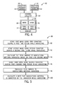
- FIG. 5 is a flowchart of an embodiment of a method 88 for determining a total amount of agricultural material harvested by a harvester 10.
- the method 88 includes measuring the first weight 68 using the first sensor 46 of the first conveyor 44 during a first time period while the harvester 10 is harvesting (block 90).
- the first sensor 46 may be a scale, a load cell, a strain gauge, or any other suitable sensor.
- the first conveyor 44 may contain multiple sensors to determine a variety of information about the material on the first conveyor 44.
- the second conveyor 48 may measure the second weight 70 during a second time period using the second sensor 50 of the second conveyor 48 while the harvester 10 is harvesting (block 92).
- the second conveyor 48 may house multiple sensors that may be used to determine a variety of information about the material on the second conveyor 48.
- the sensors within the first conveyor 44 and the second conveyor 48 may measure data corresponding to mass, weight, volume, density, moisture content, or any other information beneficial to the operator.
- the total weight 72 of agricultural material harvested by the harvester 10 may be calculated (block 94).
- the first and second time periods may coincide, but advantageously there may be a time shift between both, in order to account for differences in delay of the material reaped by the cutting assembly 12 reaching the first conveyor 44 or the second conveyor 48.
- the first weight 68, the second weight 70, and the total weight 72 may be presented on the display 66 for the operator. This information may be used to estimate additional information such as revenue, losses, and/or annual productivity.
- the harvester 10 may also measure a third weight during the first or second time period using the second conveyor 48 (block 96). For example, during the first time period, the first conveyor 44 may measure a first weight 68, and the second conveyor may measure a second weight 70. In the following second time period, the first conveyor may measure a third weight, and the second conveyor may measure an additional weight, and so on. In this way, near real-time measurements may be approximated.
- the harvester 10 may be able to convey relevant data to an operator in a timelier manner. Using the third weight and any additional weight measurements, the total amount of agricultural material may be recalculated (block 98). Furthermore, the rate that agricultural material is harvested may be calculated while the harvester 10 is harvesting (block 100). The method 88 may provide information to the user about harvesting efficiency, equipment functionality, and/or crop productivity during operation of the harvester. The harvester 10 may also be capable of generating yield maps and yield production data based on multiple data sets from multiple harvests.
Landscapes
- Life Sciences & Earth Sciences (AREA)
- Environmental Sciences (AREA)
- Engineering & Computer Science (AREA)
- Mechanical Engineering (AREA)
- Physics & Mathematics (AREA)
- General Physics & Mathematics (AREA)
- Combines (AREA)
- Threshing Machine Elements (AREA)
Abstract
Description
- The invention relates generally to agricultural equipment, such as harvesters, and more specifically, to a system and method for conveying agricultural material in a harvester.
- A harvester may be used to harvest agricultural crops, such as barley, beans, beets, carrots, corn, cotton, flax, oats, potatoes, rye, soybeans, wheat, or other plant crops. Moreover, a combine (e.g., combine harvester) is a type of harvester generally used to harvest grains (e.g., barley, corn, flax, oats, rye, soybeans, wheat, etc.). Accordingly, a combine may be used to separate a plant into different agricultural materials, such as grain and straw. During operation of a combine, the harvesting process begins by removing the plant from the ground, usually using a cutting device. The combine then separates the plant into two agricultural materials by generally directing the grain to a cleaning system and the straw toward a beater. The beater directs the straw toward a pan to further separate grain from the straw. In some combines, the cleaning system includes multiple vibrating sieves that isolate the grain from the other agricultural material and a blower that blows the agricultural material away from the grain.
- Unfortunately, the beater/pan configuration may reduce harvesting efficiency. For example, the beater is heavy and may weigh between 135 and 180 kg (300 and 400 lbs). Furthermore, the pan, placed below the beater, is curved to accommodate the beater and may restrict airflow from the blower. The blower is responsible for separating certain agricultural material (e.g., chaff and straw) from the grain. As such, the restricted airflow resulting from the pan may reduce cleaning efficiency, which may result in increased time and expense for harvesting. Furthermore, in certain combines it may be beneficial to know the amount of agricultural material being harvested by the combine while the harvester is in operation in order to adjust the harvesting process for optimal grain recovery.
- In one embodiment, a harvester includes a rotor which rotates to separate a plant into a first agricultural material and a second agricultural material. A grate is disposed vertically below the rotor and further separates the first and second agricultural materials from one another. A first conveyor receives the first and second agricultural material directly from a trailing end of the rotor and a trailing end of the grate.
- In an advantageous embodiment, a harvester includes a conveyor to receive an agricultural material, wherein the conveyor has a sensor configured to measure a weight of the agricultural material. The conveyor also has control circuitry configured to receive a signal indicative of the measured weight from the sensor.
- In a further embodiment, a method for determining a total amount of agricultural material harvested by a harvester includes measuring a first weight of the agricultural material while the agricultural material is conveyed by a first conveyor of the harvester during a first time period. A second weight of the agricultural material is measured while the agricultural material is conveyed by the second conveyor during a second time period. Further, in the method, the total amount of agricultural material harvested by the harvester is calculated, based at least partially on the first weight and the second weight.
- These and other features, aspects, and advantages of the present invention will become better understood when the following detailed description is read with reference to the accompanying drawings in which like characters represent like parts throughout the drawings, wherein:
-
FIG. 1 is a perspective view of an embodiment of a harvester which may employ a conveyor for conveying agricultural material; -
FIG. 2 is a schematic diagram of an embodiment of a harvester configured to separate a plant into a first agricultural material and a second agricultural material; -
FIG. 3 is a schematic diagram of another embodiment of a harvester configured to separate a plant into a first agricultural material and a second agricultural material; -
FIG. 4 is a block diagram of an embodiment of a harvester control system; and -
FIG. 5 is a flowchart of an embodiment of a method for determining a total amount of agricultural material harvested by a harvester. - Turning now to the drawings,
FIG. 1 is a perspective view of a harvester 10 (e.g., combine) which may employ a conveyor for conveying agricultural material. Theharvester 10 may be configured to harvest grains such as barley, corn, flax, oats, rye, soybeans, wheat, and so forth. Accordingly, theharvester 10 is configured to remove plants from the ground and to separate the plants into a first agricultural material, for example grain, and a second agricultural material, for example, material other than grain (MOG), comprising chaff and straw. Theharvester 10 includes various systems that are used during harvesting. To improve the efficiency of theharvester 10, a separation system of theharvester 10 may enhance airflow by allowing a larger clearance within the separating system. Furthermore, theharvester 10 may include a conveyor that conveys harvested grain while determining a mass of the harvested grain. - The harvesting process begins with the
harvester 10 using acutting assembly 12 to remove plants from soil. An operator of theharvester 10 may be seated in acab 14, and the operator may monitor the operation of thecutting assembly 12 and other systems of theharvester 10. After removing the plants, theharvester 10 transports the plants to arotor 16. Therotor 16 rotates to separate the grain of the plants from the straw of the plants. Specifically, therotor 16 has multiple projections on its surface that interact with the plants to facilitate separation of the grain from the straw. Grain is directed from therotor 16 further into acleaning system 20. Thecleaning system 20 is designed to further separate the grain from MOG removed with the grain (e.g., straw, soil, etc.) using ablower 18. -
FIG. 2 is a schematic diagram of an embodiment of a system configured to separate a plant into a first agricultural material and a second agricultural material. After plants are removed from the soil, the plants are directed toward aconical end 24 of therotor 16. Theconical end 24 includesblades 26 that direct the plants toward a main body portion 28 of therotor 16. The main body portion 28 includesprojections 30 that direct the plants toward agrate 32 positioned vertically below therotor 16. As illustrated, thegrate 32 has openings that enable grain to pass through thegrate 32 while blocking chaff from passing through thegrate 32, thus facilitating separation of the plants into grain and chaff. As therotor 16 rotates, therotor 16 directs the plants against thegrate 32 which may frictionally separate the grain from the chaff. While the grain falls through thegrate 32 and enters thecleaning system 20, the chaff is directed along therotor 16 and thegrate 32 toward atrailing end 34 of therotor 16 and thegrate 32. As may be appreciated, some grain may not pass through the openings in thegrate 32 and may move with the chaff out of the trailingend 34 of therotor 16. Furthermore, some chaff may pass through thegrate 32 with the grain and may enter thecleaning system 20. - The grain that falls through the
grate 32 drops onto a series ofsieves 36. Thesieves 36 vibrate and shake the grain to further separate chaff and other agricultural material from the grain. To aid in separating the agricultural materials, theblower 18 directs anairflow 38 upward through thesieves 36. Theairflow 38 blows off the chaff upwardly, thereby leaving the grain to travel through the series ofsieves 36. While fivesieves 36 are illustrated inFIG. 2 , any suitable number ofsieves 36 may be used in alternative embodiments. - When the chaff exits the
trailing end 34 of therotor 16, the chaff contacts abeater 40 and abeater pan 42. Thebeater 40 may be formed from heavy material. The weight of thebeater 40 combined with the shape of thebeater pan 42 may drive the chaff and residual grain toward aconveyor system 43. Theconveyor system 43 includes afirst conveyor 44 to convey agricultural material from the trailingend 34. Moreover, thefirst conveyor 44 includes afirst sensor 46 configured to measure a weight of the agricultural material on thefirst conveyor 44. As may be appreciated, thefirst sensor 46 may be configured to measure a weight, a volume, or any other suitable property of the agricultural material. Thefirst sensor 46 may provide the measured weight to a control system. The control system may use the measured weight to calculate information corresponding to harvesting plants, such as for producing yield maps, determining throughput, and calculating a harvesting rate. Thefirst conveyor 44 may direct the agricultural material toward thesieves 36, asecond conveyor 48, or to another location. As may be appreciated, theairflow 38 from theblower 18 may impact agricultural material being conveyed by theconveyors 44 and 48 (e.g., to separate chaff from grain). - The
second conveyor 48 may include asecond sensor 50. Similar to thefirst sensor 46, thesecond sensor 50 is configured to measure a weight of agricultural material. Furthermore, thesecond sensor 50 may be configured to measure a weight, a volume, or any other suitable property of the agricultural material disposed thereon. Thesecond sensor 50 may provide the measured weight to a control system. The control system may use the weight to calculate information corresponding to harvesting plants, such as calculations corresponding to revenue and productivity. Thesecond conveyor 48 may direct the agricultural material toward thesieves 36 or to another location. Although the depicted embodiment includes only onesensor 46 in thefirst conveyor 44, and only onesensor 50 in thesecond conveyor 48, theconveyors sensors cleaning system 20 may enable the operator to optimize the performance of theharvester 10 during the harvesting process, thereby improving harvester efficiency, reducing waste generation, and increasing revenue from the harvesting operation. Additionally, performing operation calculations during the harvesting process may save time by obviating post-harvest calculations. - After being moved by the
conveyors sieves 36, the agricultural material is directed toward a first auger 52 (e.g., clean grain cross auger), toward a second auger 54 (e.g., tailings cross auger), outside of the harvester, or elsewhere. Thefirst auger 52 may be used to convey clean grain to a clean grain elevator, while thesecond auger 54 may be used to convey tailings to a tailings return system. -
FIG. 3 is a schematic diagram of another embodiment of aharvester 10 configured to separate a plant into a first agricultural material and a second agricultural material. As illustrated, the arrangement of theconveyor system 43 directs theairflow 38 in a desired manner, thereby improving the efficiency of thecleaning system 20. In the present embodiment, as the chaff exits the trailingend 34 of therotor 16, the chaff drops directly onto thefirst conveyor 44 which contains thefirst sensor 46. As discussed previously, thefirst sensor 46 may measure the weight of the material on thefirst conveyor 44. As may be appreciated, theairflow 38 may direct chaff off of thefirst conveyor 44 so that mostly residual grain remains on thefirst conveyor 44. Accordingly, thefirst conveyor 44 may direct the residual grain toward aresidual capture system 56. - The
residual capture system 56 includes a perforated surface 58 (e.g., perforated pan) to separate the residual grain from other agricultural materials. In certain embodiments, theperforated surface 58 may operate similarly to the sieves 36 (e.g., by shaking). Furthermore, theresidual capture system 56 has a redirecting mechanism 60 (e.g., ramp) configured to direct the recovered grain toward a beginning stage of thecleaning system 20. During operation of thefirst conveyor 44, thefirst conveyor 44 may direct the residual grain onto theperforated surface 58. The perforations may enable the residual grain to drop onto the redirectingmechanism 60 while blocking other agricultural materials from dropping onto the redirectingmechanism 60. - As illustrated in
FIG. 2 , thebeater pan 42 of the other embodiment may project into the pathway of theairflow 38 causing theairflow 38 to be redirected downwardly. When redirected downwardly, theairflow 38 may not move as desired. Furthermore, the redirectedairflow 38 may interrupt the cleaning process by blowing the chaff toward thesieves 36. The interruption to the cleaning process may result in wasted agricultural material, inadequate cleaning, and/or wasted time. Alternatively, as illustrated inFIG. 3 , the present embodiment of theharvester 10 does not include thebeater 40 and thebeater pan 42. Omission of thebeater 40 and thebeater pan 42 may result in a weight reduction and/or cost reduction of theharvester 10. For example, reducing the weight of theharvester 10 may improve fuel efficiency and may increaseharvester 10 operation speed. Additionally, omission of thebeater 40 and thebeater pan 42 may improve the effectiveness of theairflow 38 from theblower 18. With thebeater pan 42 omitted, the path for theairflow 38 may have sufficient clearance between the cleaningsystem 20 and thefirst conveyor 44 so that theairflow 38 is not redirected. As in this embodiment, thecleaning system 20 and thefirst conveyor 44 may be oriented generally parallel to each other, enabling a suitable clearance for theairflow 38. By removing blockages to theairflow 38, theairflow 38 may more effectively separate the grain and the chaff. Accordingly, theairflow 38 may pass through thesieves 36 to remove the chaff without the chaff being redirected toward thesieves 36. - Furthermore, the addition of the
residual capture system 56 may improve the separation efficiency of thecleaning system 20. Instead of dropping the residual grain from thefirst conveyor 44 into a middle portion of thecleaning system 20, theresidual capture system 56 directs the residual grain toward a beginning stage of thecleaning system 20. Theperforated surface 58 functions similarly to thegrate 32 by enabling residual grain to fall through the perforations, while blocking chaff from falling through the perforations. The chaff may then be removed by theairflow 38. The improved separation efficiency of theharvester 10 may result in increased revenue and more accurate yield predictions for future harvests. -
FIG. 4 is a block diagram of an embodiment of aharvester control system 62. As may be appreciated, thecontrol system 62 may be located within thecab 14, or at another location of theharvester 10. Thecontrol system 62 includescontrol circuitry 64 configured to receive and to process data from thesensors control circuitry 64 may be configured to calculate a total weight of agricultural material conveyed by thefirst conveyor 44 and/or thesecond conveyor 48. Thecontrol system 62 also includes adisplay 66 configured to present information to an operator of theharvester 10. Thefirst sensor 46 of thefirst conveyor 44 may measure a weight of the agricultural material on thefirst conveyor 44. Similarly, thesecond sensor 50 of thesecond conveyor 48 may measure a weight from the agricultural material on thesecond conveyor 48. The measured weights may be provided to thecontrol circuitry 64. Thecontrol circuitry 64 may use the measured weights to determine information about the agricultural material on theconveyors 44 and 48 (e.g., mass/volume of the agricultural material). The resultant information from the measured weights may be presented to the operator of theharvester 10 via adisplay 66. For example, thedisplay 66 may show afirst weight 68 of agricultural material on thefirst conveyor 44, asecond weight 70 of agricultural material on thesecond conveyor 48, atotal mass 72, and afeed rate 74. - In other embodiments, the
display 66 may provide other information such as yield projections, revenue estimates, energy usage, volume harvested, total time harvesting, harvest rate, time, date, temperature, or any other data useful to the operator. In the present embodiment, theconveyors harvester 10 may include any number of conveyors and any number of sensors. For example, thefirst conveyor 44 may include three sensors, thesecond conveyor 50 may include two sensors, and a third conveyor may include five sensors. Thesensors sensors cleaning system 20 may enable the operator to adjust performance parameters of theharvester 10 during the harvesting process instead of waiting until the next harvest to adjust operation. Real-time/near real-time adjustment of operating parameters may result in improved separation efficiency, improved energy efficiency, and increased revenue from the overall harvesting operation. Additionally, performing operation calculations while harvesting may save time by obviating post-harvest calculations. -
FIG. 5 is a flowchart of an embodiment of amethod 88 for determining a total amount of agricultural material harvested by aharvester 10. Themethod 88 includes measuring thefirst weight 68 using thefirst sensor 46 of thefirst conveyor 44 during a first time period while theharvester 10 is harvesting (block 90). Thefirst sensor 46 may be a scale, a load cell, a strain gauge, or any other suitable sensor. Additionally, thefirst conveyor 44 may contain multiple sensors to determine a variety of information about the material on thefirst conveyor 44. Similarly, thesecond conveyor 48 may measure thesecond weight 70 during a second time period using thesecond sensor 50 of thesecond conveyor 48 while theharvester 10 is harvesting (block 92). Thesecond conveyor 48 may house multiple sensors that may be used to determine a variety of information about the material on thesecond conveyor 48. For example, the sensors within thefirst conveyor 44 and thesecond conveyor 48 may measure data corresponding to mass, weight, volume, density, moisture content, or any other information beneficial to the operator. Based on the first andsecond weights second sensors total weight 72 of agricultural material harvested by theharvester 10 may be calculated (block 94). The first and second time periods may coincide, but advantageously there may be a time shift between both, in order to account for differences in delay of the material reaped by the cuttingassembly 12 reaching thefirst conveyor 44 or thesecond conveyor 48. - The
first weight 68, thesecond weight 70, and thetotal weight 72 may be presented on thedisplay 66 for the operator. This information may be used to estimate additional information such as revenue, losses, and/or annual productivity. Theharvester 10 may also measure a third weight during the first or second time period using the second conveyor 48 (block 96). For example, during the first time period, thefirst conveyor 44 may measure afirst weight 68, and the second conveyor may measure asecond weight 70. In the following second time period, the first conveyor may measure a third weight, and the second conveyor may measure an additional weight, and so on. In this way, near real-time measurements may be approximated. - Using the
method 88, theharvester 10 may be able to convey relevant data to an operator in a timelier manner. Using the third weight and any additional weight measurements, the total amount of agricultural material may be recalculated (block 98). Furthermore, the rate that agricultural material is harvested may be calculated while theharvester 10 is harvesting (block 100). Themethod 88 may provide information to the user about harvesting efficiency, equipment functionality, and/or crop productivity during operation of the harvester. Theharvester 10 may also be capable of generating yield maps and yield production data based on multiple data sets from multiple harvests. - While only certain features of the invention have been illustrated and described herein, many modifications and changes will occur to those skilled in the art without departing from the scope of the invention as defined by the accompanying claims.
Claims (15)
- A harvester (10) comprising:a rotor (16) configured to rotate for separating a plant into a first agricultural material and a second agricultural material;a grate (32) disposed vertically below the rotor (16) and configured to further separate the first and second agricultural materials from one another; anda first conveyor (44) configured to receive agricultural material from the rotor,characterized in that the first conveyor (44) is arranged to receive agricultural material directly from a trailing end (34) of the rotor (16) and a trailing end (34) of the grate (32).
- A harvester according to claim 1, wherein the first agricultural material comprises grain and/or the second agricultural material comprises chaff and straw.
- A harvester according to claim 1 or 2, wherein the rotor (16) and the grate (32) are configured to enable the passage of first agricultural material through openings in the grate (32), and to block at least a portion of the second agricultural material from passing through the openings in the grate (32) and to direct said portion toward the trailing end (34) of the rotor (16) and the grate (32).
- A harvester according to any of the preceding claims, wherein the first conveyor (44) comprises a sensor (46) configured to measure a weight of the agricultural material being conveyed by the first conveyor (44) and the harvester further comprises control circuitry (64) configured to receive a signal indicative of the measured weight from the sensor (46).
- A harvester according to claim 4, comprising a second conveyor (48) configured to receive the first agricultural material from a cleaning system (20), and provided with a second sensor (50) to measure a weight of the first agricultural material.
- A harvester according to claim 5, wherein the control circuitry (64) is configured to calculate a total mass (72) of the agricultural material conveyed by the conveyors (44, 48).
- A harvester according to claim 6, comprising a display (66) configured to present the total mass (72) of the agricultural material conveyed by the conveyors (44, 48).
- A harvester according to any of the preceding claims, wherein the harvester does not comprise a beater (40) between the trailing end (34) of the rotor (16) and the first conveyor (44).
- A harvester according to any of the preceding claims, comprising a blower (18) configured to direct air (38) toward the first conveyor (44) to facilitate separation of the first and second agricultural materials from one another.
- A harvester according to claim 9, wherein the first conveyor (44) is positioned generally parallel to a cleaning system (20) to enable air (38) from the blower (18) to flow between the first conveyor (44) and the cleaning system (20).
- A harvester according to any of the preceding claims, comprising a residual capturing system (56) configured to receive first agricultural material from the first conveyor (44), and to direct this first agricultural material toward a cleaning system (20).
- A harvester according to claim 11, wherein the residual capturing system (56) comprises a redirecting mechanism (60) configured to direct first agricultural material from the first conveyor (44) toward a beginning stage of the cleaning system (20).
- A method for determining a total amount of agricultural material harvested by a harvester (10), comprising:measuring a first weight (68) of agricultural material while the agricultural material is conveyed by a first conveyor (44) of the harvester (10) during a first time period;measuring a second weight (70) of the agricultural material while the agricultural material is conveyed by a second conveyor (48) during a second time period; andmeasuring the total amount (72) of agricultural material harvested by the harvester (10) based at least partially on the first weight (68) and the second weight (70).
- A method according to claim 13, comprising measuring a third weight of the agricultural material while the agricultural material is conveyed by a third conveyor, downstream from the first conveyor (44), during the first time period, the second time, or a combination thereof.
- A method according to claim 14, comprising determining the total amount of agricultural material harvested by the harvester (10) based at least partially on the third weight.
Applications Claiming Priority (1)
| Application Number | Priority Date | Filing Date | Title |
|---|---|---|---|
| US13/679,186 US9078397B2 (en) | 2012-11-16 | 2012-11-16 | System for conveying agricultural material in a harvester |
Publications (3)
| Publication Number | Publication Date |
|---|---|
| EP2732693A2 true EP2732693A2 (en) | 2014-05-21 |
| EP2732693A3 EP2732693A3 (en) | 2018-05-30 |
| EP2732693B1 EP2732693B1 (en) | 2021-05-19 |
Family
ID=49584668
Family Applications (1)
| Application Number | Title | Priority Date | Filing Date |
|---|---|---|---|
| EP13193359.0A Active EP2732693B1 (en) | 2012-11-16 | 2013-11-18 | System and method for conveying agricultural material in a harvester |
Country Status (2)
| Country | Link |
|---|---|
| US (2) | US9078397B2 (en) |
| EP (1) | EP2732693B1 (en) |
Cited By (1)
| Publication number | Priority date | Publication date | Assignee | Title |
|---|---|---|---|---|
| EP3590320A1 (en) * | 2018-07-03 | 2020-01-08 | CNH Industrial Belgium N.V. | System and method for determining the residue yield of plant materials harvested by an agricultural harvester |
Families Citing this family (9)
| Publication number | Priority date | Publication date | Assignee | Title |
|---|---|---|---|---|
| US10219439B1 (en) * | 2017-08-14 | 2019-03-05 | Cnh Industrial America Llc | Harvester cleaning system with conveyor enhanced cascades |
| US10537918B2 (en) | 2017-11-21 | 2020-01-21 | Kringstad Ironworks, Inc. | Piler conveyor system |
| EP3958665A4 (en) * | 2019-03-07 | 2023-06-28 | Seed Terminator Holdings Pty Ltd | A chaff feed stream conditioning system |
| US11930737B2 (en) * | 2019-12-24 | 2024-03-19 | Cnh Industrial America Llc | Self-propelled windrower with yield monitoring based on merger load |
| EP4023048B1 (en) * | 2020-12-29 | 2023-06-14 | Agco Corporation | Crop test-weight system |
| US11622495B2 (en) * | 2021-06-01 | 2023-04-11 | Gint Co., Ltd. | Method of automatically combining farm vehicle and work machine and farm vehicle |
| EP4212005B1 (en) * | 2022-01-14 | 2026-03-04 | CNH Industrial Belgium N.V. | A residue collector |
| CN114557198A (en) * | 2022-03-02 | 2022-05-31 | 甘肃农业大学 | Transverse axial flow threshing device |
| US12221300B2 (en) | 2022-09-28 | 2025-02-11 | Kringstad Ironworks, Inc. | Cleanup conveyor system |
Family Cites Families (34)
| Publication number | Priority date | Publication date | Assignee | Title |
|---|---|---|---|---|
| GB1110687A (en) * | 1966-04-06 | 1968-04-24 | Ransomes Sims & Jefferies Ltd | Improvements in combine harvesters |
| US3626472A (en) * | 1969-01-09 | 1971-12-07 | Sperry Rand Corp | Means for feeding crop material to an axial flow threshing and separating combine |
| US3602230A (en) * | 1969-01-10 | 1971-08-31 | Int Harvester Co | Dust-settling device |
| US3613691A (en) * | 1969-11-04 | 1971-10-19 | Albert R Wilshusen | Grain separator for combines |
| US3794047A (en) * | 1971-08-27 | 1974-02-26 | Sperry Rand Corp | Crop feeding means for an axial flow combine having side by side threshing units |
| US3742686A (en) * | 1972-05-10 | 1973-07-03 | Sperry Rand Corp | Axial flow combine harvester |
| US4149360A (en) * | 1978-01-27 | 1979-04-17 | Sperry Rand Corporation | Axial thresher and straw walker means for combine |
| NO834290L (en) | 1983-11-23 | 1985-05-24 | Sigmund Stokland | DEVICE FOR STRAWBER TRANSPORT IN CROPS. |
| NO834291L (en) | 1983-11-23 | 1985-05-24 | Sigmund Stokland | DEVICE FOR STRAWBER TRANSPORT IN CROPS. |
| EP0208025B1 (en) * | 1985-07-12 | 1991-08-21 | Ford New Holland N.V. | Flow metering device |
| SE8603089D0 (en) | 1986-07-11 | 1986-07-11 | Rekordverken Ab | DEVICE WITH SLACK HACK PROVIDED CROPS |
| US4943260A (en) | 1988-10-05 | 1990-07-24 | Fossum Arthur J | Weed seed harvester |
| CA2180691C (en) | 1996-07-08 | 1998-11-17 | Robert H. Mcleod | Harvesting system and method |
| US6242927B1 (en) * | 1997-04-09 | 2001-06-05 | Case Corporation | Method and apparatus measuring parameters of material |
| FR2768222B1 (en) | 1997-09-05 | 1999-10-08 | Pellenc Sa | ON-BOARD AND CONTINUOUS HARVEST WEIGHING DEVICE AND METHOD, AND HARVESTING MACHINES USING THE SAME |
| US6313414B1 (en) * | 2000-01-31 | 2001-11-06 | Harvestmaster, Inc. | Slope and motion compensator for weighing on a dynamic platform |
| US7211745B1 (en) | 2003-07-22 | 2007-05-01 | The Regents Of The University Of California | Precision harvesting and analysis techniques for crops |
| EP1516522B2 (en) * | 2003-09-19 | 2023-03-29 | CLAAS Selbstfahrende Erntemaschinen GmbH | Method and device for determining the amount of tailings return |
| US7066810B2 (en) * | 2003-11-07 | 2006-06-27 | Cnh America Llc | System and method for positively discharging crop residue from a combine |
| DE10360597A1 (en) * | 2003-12-19 | 2005-07-28 | Claas Selbstfahrende Erntemaschinen Gmbh | Method and device for controlling working elements of a combine harvester |
| US7166026B2 (en) * | 2004-07-22 | 2007-01-23 | Cnh America Llc | Stepped grate for an agricultural combine |
| US7681383B2 (en) * | 2004-08-31 | 2010-03-23 | Syngenta Participations, Ag. | Dual research plot harvester with unconventional grain flow |
| US7381130B2 (en) * | 2005-04-29 | 2008-06-03 | Cnh America Llc | System and method for detecting a condition indicative of plugging of a discharge path of an agricultural combine |
| DE102005026159A1 (en) * | 2005-06-06 | 2007-01-25 | Claas Selbstfahrende Erntemaschinen Gmbh | Method for controlling a harvesting machine |
| GB0604860D0 (en) * | 2006-03-10 | 2006-04-19 | Cnh Belgium Nv | Improvements in or relating to material stream sensors |
| US7520115B2 (en) | 2006-09-15 | 2009-04-21 | Deere & Company | Header float arm load compensation |
| US20090019826A1 (en) | 2007-07-03 | 2009-01-22 | James Edward Rigney | Method and apparatus for processing plant materials for bio-fuel production |
| US7950989B2 (en) * | 2007-08-09 | 2011-05-31 | Deere & Company | Combine with an endless conveyor that can be moved between a swath depositing position and a chopper position |
| US7937923B2 (en) | 2007-10-25 | 2011-05-10 | Deere & Company | Tractor and round baler combination with automatic baling and automatic rear door opening |
| DE102008017671B4 (en) * | 2008-04-08 | 2020-09-10 | Deere & Company | Measurement arrangement for mass throughput recording with mass and volume measurement and mass density determination based on this as well as mass throughput specification for small throughputs based on the last mass density recorded |
| US8002616B2 (en) * | 2008-04-22 | 2011-08-23 | Cnh America Llc | Agricultural combine with internal cob de-husking apparatus and system |
| DE102009009817A1 (en) * | 2009-02-20 | 2010-08-26 | Claas Selbstfahrende Erntemaschinen Gmbh | Agricultural work vehicle and control unit for it |
| US7811161B1 (en) * | 2009-05-18 | 2010-10-12 | Cnh America Llc | Corn cob collection device with stowable conveyor system having positive de-husking capability |
| DE102011052282A1 (en) * | 2011-07-29 | 2013-01-31 | Claas Selbstfahrende Erntemaschinen Gmbh | Cleaning sensor for controlling crop and blower pressure distribution |
-
2012
- 2012-11-16 US US13/679,186 patent/US9078397B2/en active Active
-
2013
- 2013-11-18 EP EP13193359.0A patent/EP2732693B1/en active Active
-
2015
- 2015-06-08 US US14/733,667 patent/US9625306B2/en not_active Expired - Fee Related
Non-Patent Citations (1)
| Title |
|---|
| None |
Cited By (2)
| Publication number | Priority date | Publication date | Assignee | Title |
|---|---|---|---|---|
| EP3590320A1 (en) * | 2018-07-03 | 2020-01-08 | CNH Industrial Belgium N.V. | System and method for determining the residue yield of plant materials harvested by an agricultural harvester |
| US10820504B2 (en) | 2018-07-03 | 2020-11-03 | Cnh Industrial America Llc | System and method for determining the residue yield of plant materials harvested by an agricultural harvester |
Also Published As
| Publication number | Publication date |
|---|---|
| EP2732693B1 (en) | 2021-05-19 |
| US20150276469A1 (en) | 2015-10-01 |
| US20140141848A1 (en) | 2014-05-22 |
| EP2732693A3 (en) | 2018-05-30 |
| US9078397B2 (en) | 2015-07-14 |
| US9625306B2 (en) | 2017-04-18 |
Similar Documents
| Publication | Publication Date | Title |
|---|---|---|
| US9078397B2 (en) | System for conveying agricultural material in a harvester | |
| US9332693B1 (en) | Agricultural combine harvester with harvesting and winnowing optimization control system | |
| CN108135132B (en) | Method for operating a harvesting machine with the aid of a plant growth model | |
| CN105875030B (en) | Multi-sensor crop yield determination | |
| US8469784B1 (en) | Autonomous grain combine control system | |
| RU2580420C2 (en) | Method of controlling process of processing harvested material in combined harvester and combine harvester | |
| US10660268B2 (en) | Harvester with electromagnetic plane crop material flow sensor | |
| EP2747546B1 (en) | Harvester with cleaning system having early clean grain evacuation | |
| US20150080069A1 (en) | Arrangement for Loss Measurement in a Combine Harvester | |
| CN105705002A (en) | Combine side-shake cleaning control system | |
| EP3542616B1 (en) | Combine harvester with fan speed adjust | |
| EP3563660B1 (en) | Return pan grain presentation to a sensor | |
| US11375662B2 (en) | Apparatus and method for monitoring grain content within a tailings system of an agricultural harvester | |
| EP3761776B1 (en) | Harvesting machine with visualization system | |
| Maertens et al. | PH—power and machinery: An analytical grain flow model for a combine harvester, Part I: Design of the model | |
| US7316104B2 (en) | Arrangement for reducing soybean losses in soybean headers | |
| JP2019135953A (en) | Work support system | |
| US12213407B2 (en) | Grain cleaning system and method of controlling such | |
| US10912256B2 (en) | Air assisted shaker table | |
| US10820521B2 (en) | Volume sensor for combine harvester tailings return system | |
| EP4544898A1 (en) | Method for calibrating a tailings return sensor in a combine harvester | |
| US20260137028A1 (en) | Method for calibrating a tailings return sensor in a combine harvester | |
| US20240292788A1 (en) | Return Pan Control in a Combine Harvester | |
| Stanly | Master of Technology In Agricultural Engineering |
Legal Events
| Date | Code | Title | Description |
|---|---|---|---|
| PUAI | Public reference made under article 153(3) epc to a published international application that has entered the european phase |
Free format text: ORIGINAL CODE: 0009012 |
|
| 17P | Request for examination filed |
Effective date: 20131118 |
|
| AK | Designated contracting states |
Kind code of ref document: A2 Designated state(s): AL AT BE BG CH CY CZ DE DK EE ES FI FR GB GR HR HU IE IS IT LI LT LU LV MC MK MT NL NO PL PT RO RS SE SI SK SM TR |
|
| AX | Request for extension of the european patent |
Extension state: BA ME |
|
| RIC1 | Information provided on ipc code assigned before grant |
Ipc: A01F 12/58 20060101ALI20171115BHEP Ipc: A01F 12/385 20060101ALI20171115BHEP Ipc: A01F 12/44 20060101AFI20171115BHEP |
|
| PUAL | Search report despatched |
Free format text: ORIGINAL CODE: 0009013 |
|
| AK | Designated contracting states |
Kind code of ref document: A3 Designated state(s): AL AT BE BG CH CY CZ DE DK EE ES FI FR GB GR HR HU IE IS IT LI LT LU LV MC MK MT NL NO PL PT RO RS SE SI SK SM TR |
|
| AX | Request for extension of the european patent |
Extension state: BA ME |
|
| RIC1 | Information provided on ipc code assigned before grant |
Ipc: A01F 12/385 20060101ALI20180423BHEP Ipc: A01F 12/44 20060101AFI20180423BHEP Ipc: A01D 41/127 20060101ALI20180423BHEP Ipc: A01F 12/58 20060101ALI20180423BHEP |
|
| STAA | Information on the status of an ep patent application or granted ep patent |
Free format text: STATUS: REQUEST FOR EXAMINATION WAS MADE |
|
| R17P | Request for examination filed (corrected) |
Effective date: 20181130 |
|
| RBV | Designated contracting states (corrected) |
Designated state(s): AL AT BE BG CH CY CZ DE DK EE ES FI FR GB GR HR HU IE IS IT LI LT LU LV MC MK MT NL NO PL PT RO RS SE SI SK SM TR |
|
| GRAP | Despatch of communication of intention to grant a patent |
Free format text: ORIGINAL CODE: EPIDOSNIGR1 |
|
| STAA | Information on the status of an ep patent application or granted ep patent |
Free format text: STATUS: GRANT OF PATENT IS INTENDED |
|
| INTG | Intention to grant announced |
Effective date: 20201215 |
|
| GRAS | Grant fee paid |
Free format text: ORIGINAL CODE: EPIDOSNIGR3 |
|
| GRAA | (expected) grant |
Free format text: ORIGINAL CODE: 0009210 |
|
| STAA | Information on the status of an ep patent application or granted ep patent |
Free format text: STATUS: THE PATENT HAS BEEN GRANTED |
|
| AK | Designated contracting states |
Kind code of ref document: B1 Designated state(s): AL AT BE BG CH CY CZ DE DK EE ES FI FR GB GR HR HU IE IS IT LI LT LU LV MC MK MT NL NO PL PT RO RS SE SI SK SM TR |
|
| REG | Reference to a national code |
Ref country code: GB Ref legal event code: FG4D |
|
| REG | Reference to a national code |
Ref country code: CH Ref legal event code: EP |
|
| REG | Reference to a national code |
Ref country code: DE Ref legal event code: R096 Ref document number: 602013077519 Country of ref document: DE |
|
| REG | Reference to a national code |
Ref country code: AT Ref legal event code: REF Ref document number: 1393089 Country of ref document: AT Kind code of ref document: T Effective date: 20210615 |
|
| REG | Reference to a national code |
Ref country code: IE Ref legal event code: FG4D |
|
| REG | Reference to a national code |
Ref country code: LT Ref legal event code: MG9D |
|
| REG | Reference to a national code |
Ref country code: AT Ref legal event code: MK05 Ref document number: 1393089 Country of ref document: AT Kind code of ref document: T Effective date: 20210519 |
|
| REG | Reference to a national code |
Ref country code: NL Ref legal event code: MP Effective date: 20210519 |
|
| PG25 | Lapsed in a contracting state [announced via postgrant information from national office to epo] |
Ref country code: LT Free format text: LAPSE BECAUSE OF FAILURE TO SUBMIT A TRANSLATION OF THE DESCRIPTION OR TO PAY THE FEE WITHIN THE PRESCRIBED TIME-LIMIT Effective date: 20210519 Ref country code: FI Free format text: LAPSE BECAUSE OF FAILURE TO SUBMIT A TRANSLATION OF THE DESCRIPTION OR TO PAY THE FEE WITHIN THE PRESCRIBED TIME-LIMIT Effective date: 20210519 Ref country code: BG Free format text: LAPSE BECAUSE OF FAILURE TO SUBMIT A TRANSLATION OF THE DESCRIPTION OR TO PAY THE FEE WITHIN THE PRESCRIBED TIME-LIMIT Effective date: 20210819 Ref country code: AT Free format text: LAPSE BECAUSE OF FAILURE TO SUBMIT A TRANSLATION OF THE DESCRIPTION OR TO PAY THE FEE WITHIN THE PRESCRIBED TIME-LIMIT Effective date: 20210519 Ref country code: HR Free format text: LAPSE BECAUSE OF FAILURE TO SUBMIT A TRANSLATION OF THE DESCRIPTION OR TO PAY THE FEE WITHIN THE PRESCRIBED TIME-LIMIT Effective date: 20210519 |
|
| PG25 | Lapsed in a contracting state [announced via postgrant information from national office to epo] |
Ref country code: PL Free format text: LAPSE BECAUSE OF FAILURE TO SUBMIT A TRANSLATION OF THE DESCRIPTION OR TO PAY THE FEE WITHIN THE PRESCRIBED TIME-LIMIT Effective date: 20210519 Ref country code: NO Free format text: LAPSE BECAUSE OF FAILURE TO SUBMIT A TRANSLATION OF THE DESCRIPTION OR TO PAY THE FEE WITHIN THE PRESCRIBED TIME-LIMIT Effective date: 20210819 Ref country code: PT Free format text: LAPSE BECAUSE OF FAILURE TO SUBMIT A TRANSLATION OF THE DESCRIPTION OR TO PAY THE FEE WITHIN THE PRESCRIBED TIME-LIMIT Effective date: 20210920 Ref country code: ES Free format text: LAPSE BECAUSE OF FAILURE TO SUBMIT A TRANSLATION OF THE DESCRIPTION OR TO PAY THE FEE WITHIN THE PRESCRIBED TIME-LIMIT Effective date: 20210519 Ref country code: IS Free format text: LAPSE BECAUSE OF FAILURE TO SUBMIT A TRANSLATION OF THE DESCRIPTION OR TO PAY THE FEE WITHIN THE PRESCRIBED TIME-LIMIT Effective date: 20210919 Ref country code: LV Free format text: LAPSE BECAUSE OF FAILURE TO SUBMIT A TRANSLATION OF THE DESCRIPTION OR TO PAY THE FEE WITHIN THE PRESCRIBED TIME-LIMIT Effective date: 20210519 Ref country code: GR Free format text: LAPSE BECAUSE OF FAILURE TO SUBMIT A TRANSLATION OF THE DESCRIPTION OR TO PAY THE FEE WITHIN THE PRESCRIBED TIME-LIMIT Effective date: 20210820 Ref country code: RS Free format text: LAPSE BECAUSE OF FAILURE TO SUBMIT A TRANSLATION OF THE DESCRIPTION OR TO PAY THE FEE WITHIN THE PRESCRIBED TIME-LIMIT Effective date: 20210519 Ref country code: SE Free format text: LAPSE BECAUSE OF FAILURE TO SUBMIT A TRANSLATION OF THE DESCRIPTION OR TO PAY THE FEE WITHIN THE PRESCRIBED TIME-LIMIT Effective date: 20210519 |
|
| PG25 | Lapsed in a contracting state [announced via postgrant information from national office to epo] |
Ref country code: NL Free format text: LAPSE BECAUSE OF FAILURE TO SUBMIT A TRANSLATION OF THE DESCRIPTION OR TO PAY THE FEE WITHIN THE PRESCRIBED TIME-LIMIT Effective date: 20210519 |
|
| PG25 | Lapsed in a contracting state [announced via postgrant information from national office to epo] |
Ref country code: SK Free format text: LAPSE BECAUSE OF FAILURE TO SUBMIT A TRANSLATION OF THE DESCRIPTION OR TO PAY THE FEE WITHIN THE PRESCRIBED TIME-LIMIT Effective date: 20210519 Ref country code: SM Free format text: LAPSE BECAUSE OF FAILURE TO SUBMIT A TRANSLATION OF THE DESCRIPTION OR TO PAY THE FEE WITHIN THE PRESCRIBED TIME-LIMIT Effective date: 20210519 Ref country code: DK Free format text: LAPSE BECAUSE OF FAILURE TO SUBMIT A TRANSLATION OF THE DESCRIPTION OR TO PAY THE FEE WITHIN THE PRESCRIBED TIME-LIMIT Effective date: 20210519 Ref country code: EE Free format text: LAPSE BECAUSE OF FAILURE TO SUBMIT A TRANSLATION OF THE DESCRIPTION OR TO PAY THE FEE WITHIN THE PRESCRIBED TIME-LIMIT Effective date: 20210519 Ref country code: CZ Free format text: LAPSE BECAUSE OF FAILURE TO SUBMIT A TRANSLATION OF THE DESCRIPTION OR TO PAY THE FEE WITHIN THE PRESCRIBED TIME-LIMIT Effective date: 20210519 Ref country code: RO Free format text: LAPSE BECAUSE OF FAILURE TO SUBMIT A TRANSLATION OF THE DESCRIPTION OR TO PAY THE FEE WITHIN THE PRESCRIBED TIME-LIMIT Effective date: 20210519 |
|
| REG | Reference to a national code |
Ref country code: DE Ref legal event code: R097 Ref document number: 602013077519 Country of ref document: DE |
|
| PLBE | No opposition filed within time limit |
Free format text: ORIGINAL CODE: 0009261 |
|
| STAA | Information on the status of an ep patent application or granted ep patent |
Free format text: STATUS: NO OPPOSITION FILED WITHIN TIME LIMIT |
|
| 26N | No opposition filed |
Effective date: 20220222 |
|
| PG25 | Lapsed in a contracting state [announced via postgrant information from national office to epo] |
Ref country code: IS Free format text: LAPSE BECAUSE OF FAILURE TO SUBMIT A TRANSLATION OF THE DESCRIPTION OR TO PAY THE FEE WITHIN THE PRESCRIBED TIME-LIMIT Effective date: 20210919 Ref country code: AL Free format text: LAPSE BECAUSE OF FAILURE TO SUBMIT A TRANSLATION OF THE DESCRIPTION OR TO PAY THE FEE WITHIN THE PRESCRIBED TIME-LIMIT Effective date: 20210519 |
|
| PG25 | Lapsed in a contracting state [announced via postgrant information from national office to epo] |
Ref country code: MC Free format text: LAPSE BECAUSE OF FAILURE TO SUBMIT A TRANSLATION OF THE DESCRIPTION OR TO PAY THE FEE WITHIN THE PRESCRIBED TIME-LIMIT Effective date: 20210519 |
|
| REG | Reference to a national code |
Ref country code: CH Ref legal event code: PL |
|
| PG25 | Lapsed in a contracting state [announced via postgrant information from national office to epo] |
Ref country code: LU Free format text: LAPSE BECAUSE OF NON-PAYMENT OF DUE FEES Effective date: 20211118 Ref country code: BE Free format text: LAPSE BECAUSE OF NON-PAYMENT OF DUE FEES Effective date: 20211130 |
|
| REG | Reference to a national code |
Ref country code: BE Ref legal event code: MM Effective date: 20211130 |
|
| PG25 | Lapsed in a contracting state [announced via postgrant information from national office to epo] |
Ref country code: IE Free format text: LAPSE BECAUSE OF NON-PAYMENT OF DUE FEES Effective date: 20211118 |
|
| PG25 | Lapsed in a contracting state [announced via postgrant information from national office to epo] |
Ref country code: HU Free format text: LAPSE BECAUSE OF FAILURE TO SUBMIT A TRANSLATION OF THE DESCRIPTION OR TO PAY THE FEE WITHIN THE PRESCRIBED TIME-LIMIT; INVALID AB INITIO Effective date: 20131118 |
|
| PG25 | Lapsed in a contracting state [announced via postgrant information from national office to epo] |
Ref country code: CY Free format text: LAPSE BECAUSE OF FAILURE TO SUBMIT A TRANSLATION OF THE DESCRIPTION OR TO PAY THE FEE WITHIN THE PRESCRIBED TIME-LIMIT Effective date: 20210519 |
|
| PG25 | Lapsed in a contracting state [announced via postgrant information from national office to epo] |
Ref country code: LI Free format text: LAPSE BECAUSE OF NON-PAYMENT OF DUE FEES Effective date: 20220701 Ref country code: CH Free format text: LAPSE BECAUSE OF NON-PAYMENT OF DUE FEES Effective date: 20220701 |
|
| PG25 | Lapsed in a contracting state [announced via postgrant information from national office to epo] |
Ref country code: MK Free format text: LAPSE BECAUSE OF FAILURE TO SUBMIT A TRANSLATION OF THE DESCRIPTION OR TO PAY THE FEE WITHIN THE PRESCRIBED TIME-LIMIT Effective date: 20210519 |
|
| PG25 | Lapsed in a contracting state [announced via postgrant information from national office to epo] |
Ref country code: MT Free format text: LAPSE BECAUSE OF FAILURE TO SUBMIT A TRANSLATION OF THE DESCRIPTION OR TO PAY THE FEE WITHIN THE PRESCRIBED TIME-LIMIT Effective date: 20210519 |
|
| PGFP | Annual fee paid to national office [announced via postgrant information from national office to epo] |
Ref country code: FR Payment date: 20241126 Year of fee payment: 12 |
|
| PG25 | Lapsed in a contracting state [announced via postgrant information from national office to epo] |
Ref country code: TR Free format text: LAPSE BECAUSE OF FAILURE TO SUBMIT A TRANSLATION OF THE DESCRIPTION OR TO PAY THE FEE WITHIN THE PRESCRIBED TIME-LIMIT Effective date: 20210519 |
|
| PGFP | Annual fee paid to national office [announced via postgrant information from national office to epo] |
Ref country code: DE Payment date: 20251126 Year of fee payment: 13 |
|
| PGFP | Annual fee paid to national office [announced via postgrant information from national office to epo] |
Ref country code: GB Payment date: 20251125 Year of fee payment: 13 |
|
| PGFP | Annual fee paid to national office [announced via postgrant information from national office to epo] |
Ref country code: IT Payment date: 20251121 Year of fee payment: 13 |