EP2732688A1 - Unloader system for an agricultural combine - Google Patents
Unloader system for an agricultural combine Download PDFInfo
- Publication number
- EP2732688A1 EP2732688A1 EP13192387.2A EP13192387A EP2732688A1 EP 2732688 A1 EP2732688 A1 EP 2732688A1 EP 13192387 A EP13192387 A EP 13192387A EP 2732688 A1 EP2732688 A1 EP 2732688A1
- Authority
- EP
- European Patent Office
- Prior art keywords
- grain
- unloader
- discharge
- discharge opening
- sensor
- Prior art date
- Legal status (The legal status is an assumption and is not a legal conclusion. Google has not performed a legal analysis and makes no representation as to the accuracy of the status listed.)
- Granted
Links
Images


Classifications
-
- A—HUMAN NECESSITIES
- A01—AGRICULTURE; FORESTRY; ANIMAL HUSBANDRY; HUNTING; TRAPPING; FISHING
- A01D—HARVESTING; MOWING
- A01D41/00—Combines, i.e. harvesters or mowers combined with threshing devices
- A01D41/12—Details of combines
- A01D41/1208—Tanks for grain or chaff
- A01D41/1217—Unloading mechanisms
-
- A—HUMAN NECESSITIES
- A01—AGRICULTURE; FORESTRY; ANIMAL HUSBANDRY; HUNTING; TRAPPING; FISHING
- A01D—HARVESTING; MOWING
- A01D41/00—Combines, i.e. harvesters or mowers combined with threshing devices
- A01D41/12—Details of combines
- A01D41/1208—Tanks for grain or chaff
Definitions
- the present invention relates generally to an agricultural combine having an unloader system.
- the present invention relates to an agricultural combine having an unloader system with an unloader tube configured to discharge into one of a plurality of grain tanks.
- Conventional unloader systems allow for grain harvested by agricultural combines to be delivered to a single grain location, such as a grain tank onboard the combine. Grain can then be offloaded from the combine into separate containers not onboard the combine for transport.
- conventional unloader systems have a few operational drawbacks. For example, the harvested grain must be delivered to a single grain location on the combine and then later, when the tank is full, moved to a new location. This method increases the amount of time it takes to unload grain and thus increases the amount of time and resources that must be spent in the field harvesting the grain. Further, all of the grain harvested ends up in the same single grain tank and further separation of the grain may be needed based on various attributes of the grain, which then involves a subsequent process.
- US 3,365,086 discloses a grain storage system for a combine that provides for a split grain tank and an unloading system that can direct grain into the one or other half, in order to optimize stability of the harvester on lateral slopes. However no means are provided to divide the grain flow according to any attribute of the grain.
- the present invention provides an agricultural combine that includes a first grain tank, a second grain tank and an unloader system.
- the unloader system includes an unloader tube, a sensor and a controller.
- the unloader tube includes an interior passageway, a conveyor extending along the interior passageway for conveying grain through the unloader tube, a first discharge opening, a first discharge assembly adjacent the first discharge opening, a second discharge opening and a second discharge assembly adjacent the second discharge opening, wherein the first discharge opening discharges grain traveling through the unloader tube to the first grain tank and the second discharge opening discharges grain traveling through the unloader tube to the second grain tank.
- the sensor senses an attribute of the grain harvested by the combine.
- the controller is operatively connected to and in communication with the unloader system and the sensor.
- the controller is configured to discharge the grain from the unloader tube to one of the first and second grain tanks based upon the attribute of the grain detected by the sensor.
- the present invention provides a method of discharging grain on an agricultural combine that includes providing a plurality of grain tanks, providing an unloader tube having a conveyor, a plurality of openings and a plurality of discharge assemblies moveable between open and closed positions, providing a sensor for determining an attribute of grain being unloaded through the unloader tube and providing a controller operatively connected to and in communication with the sensor and the plurality of discharge assemblies on the unloader tube.
- the controller is configured to move one of the plurality of discharge assemblies to the open position based upon a detected attribute of the grain by the sensor for depositing the grain within one of the plurality of grain tanks.
- grain refers to that part of a crop which is harvested and separated from discardable portions of the crop material.
- the present invention provides an agricultural combine 10 having a plurality of grain tanks 12, such as a first grain tank 12a and a second grain tank 12b, an unloader system 14, a sensor 46 and a controller 48.
- the agricultural combine 10 includes a body supported by wheels and an engine (not shown) for driving the wheels to allow the agricultural combine 10 to move from place to place within the field.
- An operator's station is positioned towards the forward end of the agricultural combine 10 and includes controls to allow the operator to adjust the functions of the agricultural combine 10.
- a grain harvesting header that severs and gathers the grain material from the field. After harvesting the grain materials or collecting the grain materials, the grain materials are fed rearward through a feeder housing to the combine's internal threshing system (not shown). The threshing system then separates the grain from the unwanted crop residue. Because the present invention is applicable to a variety of different threshing systems and because threshing systems are generally well-known to those skilled in the art, a detailed discussion of the structure, function and operation of such threshing systems is not necessary for a complete understanding of the present invention.
- the grain is transferred to the unloader system 14, which is used to load grain on to the combine's grain tanks and to offload grain from the grain tanks e.g., to off-machine grain tanks.
- the agricultural combine 10 has two separate grain tanks, the first grain tank 12a and the second grain tank 12b.
- the combine 10 can be configured with more than two grain tanks, such as three, four, five, or more separate grain tanks.
- the grain tanks 12a, 12b are located onboard the agricultural combine 10.
- some or all of the grain tanks e.g., grain tank 12c can be located off-machine on a grain trailer.
- the grain trailer is a detached trailer that can travel in tandem with the agricultural combine 10 and which is capable of leaving the combine to empty its payload when at full capacity. Configuring one or more grain tanks 12a, 12b, 12c to be located on-machine and/or off-machine allows for the combine 10 to maximize efficiency when harvesting the grain.
- the unloader system 14 includes an unloader tube 16.
- the unloader tube 16 includes an interior passageway 18, a conveyor 24 extending through the interior passageway 18 and at least a first discharge assembly 26 and a second discharge assembly 28.
- the interior passageway 18 has a proximal end 20 and a distal end 22 opposite the proximal end 20 and extends completely through the unloader tube 16 so as to provide a passageway for the conveyance of grain therethrough.
- the proximal end 20 is the end of the unloader tube directly connected to the combine.
- the interior passageway 18 has an annular body with a circular cross-section.
- the interior passageway 18 can be configured to have a cross-section perpendicular to a longitudinal axis A of the unloader tube 16 of any suitable shape, such as, but not limited to a square cross-section, an oval cross-section, a triangular cross-section, or a hexagonal cross-section.
- the unloader tube 16 can be an open-topped unloader tube. That is, the open-topped unloader tube can have a substantially "U" shaped cross-section or be of a planar configuration with side walls.
- the conveyor 24 is preferably a screw auger conveyor 24, but can alternatively by any conveyor capable of moving grain through the unloader tube 16, such as a paddle system, a conveyor belt, a pressure based system, or any combination thereof.
- a drive mechanism such as a motor (not shown) powers the conveyor 24.
- the unloader tube 16 includes a first discharge opening 30 positioned about a mid portion of the unloader tube 16 and at a bottom side of the unloader tube 16.
- the first discharge opening 30 is sized and shaped to allow for a continuous flow of grain traveling through the unloader tube 16 to discharge therethrough.
- the first discharge opening 30 is positioned about the outer periphery of the unloader tube 16 to discharge into the first gain tank 12a when the unloader tube 16 is positioned in a fixed predetermined discharge position.
- the fixed predetermined discharge position is a position that allows grain to be discharged in the first grain tank 12a from the first discharge opening 30 and into the second grain tank 12b from the second discharge opening 36 when in the fixed position. It is understood that the fixed discharge position is determined with respect to the position of the first grain tank 12a and the second grain tank 12b.
- the first discharge assembly 26 includes a first cover 32 moveable between an open position and closed position.
- the first cover 32 is sized and shaped to allow the first cover 32 to completely cover the first discharge opening 30, so as to prevent the outflow of grain from the first discharge opening 30 when the cover is in the closed position.
- the first cover 32 can be configured slightly larger than the first discharge opening 30 so as to have a partial or complete overlapping edge of the first cover 32 when covering the first discharge opening 30.
- the first cover 32 In the open position, the first cover 32 is spaced from the first discharge opening 30 to allow for a flow grain to travel through the first discharge opening 30.
- the first cover 32 is pivotably attached to the unloader tube 16 so as to pivot between open and closed positions.
- the first discharge assembly 26 includes an actuator 34 that moves the cover 32 between the open and closed positions.
- the actuator 34 can alternatively be any other means capable of moving the cover 32 between the open and closed positions.
- the means to move the cover 32 between the open and closed positions can be a cylinder, a hydraulic actuator, an electric actuator, a motor, or a manually operable lever.
- the first cover 32 can alternatively be configured as a sliding cover 132 that slides relative to the outer surface of the unloader tube 16 between open and closed positions for covering and uncovering the first opening 130, as shown in Fig. 2A .
- the actuator 34 is located along the external bottom surface of the unloader tube 16.
- the actuator 34 can be located anywhere along the unloader tube 16 as long as the actuator 34 is connected to and in communication with the controller 48 and can move the cover 32 between the open and closed positions.
- the first cover 32 When in a closed position, the first cover 32 engages and completely covers the first discharge opening 30 and does not allow any grain to flow out of the unloader tube 16 at the first discharge opening 30 (i.e., the cover covers the discharge opening to prevent the flow of grain from passing through the discharge opening). As a result, the grain either discharges from the second discharge opening 36 or continues along the unloader tube 16 so as to discharge from a third discharge opening 44 formed about the distal end 22 of the unloader tube 16, as best shown in Fig. 2 .
- the first cover 32 When the first cover 32 is in the open position, grain can freely flow out of the first discharge opening 30 located about the midsection of the unloader tube 16 and enter the first grain tank 12a. Further, when the first cover 32 is in the open position, grain is prevented from traveling further downstream the unloader tube for discharge through the second and third discharge openings.
- the second discharge assembly 28 includes a second cover 40 moveable between open and closed positions.
- the second discharge assembly 28 is configured similar to the first discharge assembly 26, but is positioned downstream of the first discharge assembly 26 and upstream of the third discharge opening 44. Positioning the second discharge assembly 28 downstream the first discharge assembly 26 advantageously allows for the unloader tube 16 to discharge grain in either the first tank 12a or the second tank 12b positioned adjacent to the first tank 12a.
- the first and second discharge openings 30', 36' can be positioned adjacent each other in a side by side or medial/lateral configuration, as opposed to one being positioned downstream from the other.
- the first and second grain tanks 12a', 12b' are configured in a side by side configuration to allow for grain discharging from the first discharge opening 30' to discharge into the first tank 12a' and grain discharging from the second discharge opening 36' to discharge into the second tank 12b'.
- the unloader tube 16 is positioned to extend substantially parallel to a wall separating the first grain tank 12a and the second grain tank 12b (i.e., the predetermined discharge position for the unloader tube 16 is aligned with the wall separating the grain tanks).
- the first and second discharge openings 30', 36' have corresponding first and second discharge assemblies similar to the first and second discharge assemblies 26, 28.
- the unloader tube 16 includes a first discharge opening 30" and a first discharge assembly (not shown) located about a midpoint of the unloader tube 16 and second discharge opening 36" located about the distal end 22 of the unloader tube 16.
- first discharge assembly of the present embodiment can be configured similarly to the first discharge assembly 26.
- the agricultural combine 10 includes the sensor 46 and a controller 48 in communication with the sensor 46.
- the sensor 46 detects an attribute of the grain harvested by the combine, such as protein content, moisture content, mass of material other than grain, size, density, color or any combination thereof.
- the sensor 46 can be any sensor known in the art and capable of detecting one or more attributes of grain.
- the agricultural combine 10 can include a plurality of sensors 46 for detecting a plurality of attributes in the grain.
- the sensor 46 can be located at any position of the combine 10 where it contacts with or operatively engages with the grain. Preferably, the sensor 46 is positioned at a location before the grain enters the unloader tube 16 or within the unloader tube 16 as long as the grain passes the sensor 46 before reaching the discharge openings 30, 36, or 44.
- the sensor 46 is also configured to intermittently or continuously monitor one or more attributes of the grain.
- the controller 48 can be any controller readily known in the art, such as a computer, logic controller, or part of the combine's onboard control system.
- the controller 48 is operatively connected to in and communication with both the sensor 46 and the discharge assemblies 26, 28.
- the controller 48 is operatively connected to and in communication with the actuators 34, 42 of the first and second discharge assemblies 26, 28.
- the controller 48 functions to actuate the actuators 34, 42 to move the covers 32, 40 of the first and second discharge assemblies 26, 28 between open and closed positions for covering and uncovering the first and second openings 30, 36.
- the agricultural combine 10 intakes harvested grain through a cleaning process, removes waste and captures the grain.
- the processed grain is then conveyed to the unloader system 14 located on the agricultural combine 10.
- the unloader system's proximal end 20 is linked to the internal workings of the agricultural combine 10 and connected to receive the grain.
- the sensor 46 is configured to detect an attribute of the grain, such as moisture content.
- the controller 48 receives attribute information of the grain from the sensor 46 and then determines which of the first, second and third discharge openings 30, 36, 44 to discharge the grain through. After the controller 48 determines which discharge opening to discharge the grain through, the controller 48 actuates the appropriate actuator 34, 42 to open either cover 32 or 40 of the first and second discharge assemblies 26, 28 or maintain the covers 32 and 40 in the closed position, so as to force the grain to discharge from the third discharge opening 44.
- the controller 48 determines which grain tank to discharge into based upon a predetermined specification of the on-machine grain tank or off-machine grain tank.
- the controller 48 after receiving information about the grain from the sensor 46, makes a decision on which of the plurality of grain tanks e.g., 12a, 12b, 12c the grain should end up being deposited in. If the grain is going to be deposited into the on-machine first grain tank 12a then the controller 48 sends an "open" signal to the actuator 34 of the first grain opening assembly 26. The actuator 34 then proceeds to move the cover 32 to an open position, as shown in Fig. 2 , so the first discharge opening 30 is free from encumbrances and grain can exit the interior passageway 18 and freely flow into the on-machine first grain tank 12a.
- the unloader system 14 can be configured to switch operations so as to unload into another grain tank, such as the second grain tank 12b. That is, e.g., when the sensor 46 detects that the attribute has reached a critical point, such as moisture content above a predetermined amount, the controller 48 is configured to close the first discharge assembly 26 and open the second discharge assembly 28 so as to discharge grain into the second grain tank 12b.
- a critical point such as moisture content above a predetermined amount
- the controller 48 determines that the grain must be deposited in the third grain tank 12c located off-machine, then the controller 48 sends a "close" signal to the actuators 34, 42 to close both the first and second discharge assemblies 26, 28.
- the covers 32, 40 are in the closed position, the grain continues to flow along the interior passageway 18 via the conveyor 24 so as to reach the distal end 22 of the interior passageway 18 and discharge out of the third discharge opening 44 and be deposited into the off-machine grain tank 12c.
- the unloader system 14 is positioned above the agricultural combine 10 so that the first discharge opening 30 and second discharge opening 36 are positioned above the first grain tank 12a and the second grain tank 12b, respectively. If it is determined, based upon the attributes found in the grain by the sensor 46 that the grain must be discharged off-machine, then the unloader system 14 can rotate the unloader tube 16 so as to position the third discharge opening 44 above the off-machine grain tank 12c.
- the off-machine grain tank 12c may be located to the rear of the agricultural combine 10 or on either side of the agricultural combine 10.
- the present invention provides a method of discharging grain 100.
- the method includes the step of providing a plurality of grain tanks 12a, 12b, 12c as described in any of the above embodiments (Step 102) and providing an unloader tube 16 having a conveyor 24 and a plurality of discharge openings 30, 36 and a plurality of corresponding discharge assemblies 26, 28 for covering and uncovering the discharge openings 30, 36 (Step 104).
- the method further includes providing at least one sensor 46 for determining an attribute of the grain being unloaded through an unloader tube 16 (Step 106).
- the method includes providing a controller 48 operatively connected to and in communication with the sensor 46 and the plurality of discharge assemblies 26, 28 on the unloader tube 16 (Step 108).
- the controller 48 is configured to open one of the plurality of discharge assemblies 26, 28 based upon a detected attribute of the grain by the sensor 46 for depositing the grain within one of the plurality of grain tanks 12a, 12b, 12c.
Landscapes
- Life Sciences & Earth Sciences (AREA)
- Environmental Sciences (AREA)
- Threshing Machine Elements (AREA)
Abstract
Description
- The present invention relates generally to an agricultural combine having an unloader system. In particular, the present invention relates to an agricultural combine having an unloader system with an unloader tube configured to discharge into one of a plurality of grain tanks.
- Conventional unloader systems allow for grain harvested by agricultural combines to be delivered to a single grain location, such as a grain tank onboard the combine. Grain can then be offloaded from the combine into separate containers not onboard the combine for transport. However, conventional unloader systems have a few operational drawbacks. For example, the harvested grain must be delivered to a single grain location on the combine and then later, when the tank is full, moved to a new location. This method increases the amount of time it takes to unload grain and thus increases the amount of time and resources that must be spent in the field harvesting the grain. Further, all of the grain harvested ends up in the same single grain tank and further separation of the grain may be needed based on various attributes of the grain, which then involves a subsequent process.
-
US 3,365,086 discloses a grain storage system for a combine that provides for a split grain tank and an unloading system that can direct grain into the one or other half, in order to optimize stability of the harvester on lateral slopes. However no means are provided to divide the grain flow according to any attribute of the grain. - Thus, there is still a need for an agricultural combine unloader system that is capable of addressing the aforementioned problems of conventional agricultural combines. Such a need is satisfied by the agricultural combine unloader system of the present invention.
- In a first aspect, the present invention provides an agricultural combine that includes a first grain tank, a second grain tank and an unloader system. The unloader system includes an unloader tube, a sensor and a controller. The unloader tube includes an interior passageway, a conveyor extending along the interior passageway for conveying grain through the unloader tube, a first discharge opening, a first discharge assembly adjacent the first discharge opening, a second discharge opening and a second discharge assembly adjacent the second discharge opening, wherein the first discharge opening discharges grain traveling through the unloader tube to the first grain tank and the second discharge opening discharges grain traveling through the unloader tube to the second grain tank. The sensor senses an attribute of the grain harvested by the combine. The controller is operatively connected to and in communication with the unloader system and the sensor. The controller is configured to discharge the grain from the unloader tube to one of the first and second grain tanks based upon the attribute of the grain detected by the sensor.
- In a second aspect, the present invention provides a method of discharging grain on an agricultural combine that includes providing a plurality of grain tanks, providing an unloader tube having a conveyor, a plurality of openings and a plurality of discharge assemblies moveable between open and closed positions, providing a sensor for determining an attribute of grain being unloaded through the unloader tube and providing a controller operatively connected to and in communication with the sensor and the plurality of discharge assemblies on the unloader tube. The controller is configured to move one of the plurality of discharge assemblies to the open position based upon a detected attribute of the grain by the sensor for depositing the grain within one of the plurality of grain tanks.
- The foregoing summary, as well as the following detailed description of the preferred embodiments of the invention, will be better understood when read in conjunction with the appended drawings. For the purpose of illustrating the invention, there are shown in the drawings embodiments which are presently preferred.
- In the drawings:
-
Fig. 1 is an elevation view of an agricultural combine with an unloader system in accordance with a first preferred embodiment of the present invention; -
Fig. 2 is a partial, side, cross-sectional view of an unloader tube in accordance with a preferred embodiment of the present invention; -
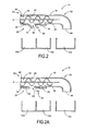
Fig. 2A is a partial, side, cross-sectional view of an unloader tube in accordance with another aspect of the present invention; -
Fig. 3 is a partial, plan, cross-sectional view of the unloader tube in accordance with a second preferred embodiment of the present invention; -
Fig. 4 is a partial, plan, cross-sectional view of the unloader tube in accordance with a third preferred embodiment of the present invention; -
Fig. 5 is a schematic block diagram of a control system in accordance with a preferred embodiment of the present invention; and -
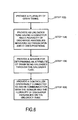
Fig. 6 is a flowchart of a method in accordance with another preferred embodiment of the present invention. - Reference will now be made in detail to the preferred embodiments of the invention illustrated in the accompanying drawings. Wherever possible, the same or like reference numbers will be used throughout the drawings to refer to the same or like features. It should be noted that the drawings are in simplified form and are not drawn to precise scale. In reference to the disclosure herein, for purposes of convenience and clarity only, directional terms such as top, bottom, above, below and diagonal, are used with respect to the accompanying drawings. Such directional terms used in conjunction with the following description of the drawings should not be construed to limit the scope of the invention in any manner not explicitly set forth. Additionally, the term "a," as used in the specification, means "at least one." The terminology includes the words above specifically mentioned, derivatives thereof, and words of similar import.
- The terms "grain," "tailing," and "crop material" are used throughout the specification for convenience and it should be understood that these terms are not intended to be limiting. Thus, "grain" refers to that part of a crop which is harvested and separated from discardable portions of the crop material.
- Referring to
Figs. 1 ,2 and5 , in a preferred embodiment, the present invention provides anagricultural combine 10 having a plurality ofgrain tanks 12, such as afirst grain tank 12a and asecond grain tank 12b, anunloader system 14, asensor 46 and acontroller 48. - The
agricultural combine 10 includes a body supported by wheels and an engine (not shown) for driving the wheels to allow theagricultural combine 10 to move from place to place within the field. An operator's station is positioned towards the forward end of theagricultural combine 10 and includes controls to allow the operator to adjust the functions of theagricultural combine 10. Such features of anagricultural combine 10 are known in the art and a detailed description of their structure, function and operation is not necessary for a complete understanding of the present invention. - At the forward end of the
agricultural combine 10 is a grain harvesting header that severs and gathers the grain material from the field. After harvesting the grain materials or collecting the grain materials, the grain materials are fed rearward through a feeder housing to the combine's internal threshing system (not shown). The threshing system then separates the grain from the unwanted crop residue. Because the present invention is applicable to a variety of different threshing systems and because threshing systems are generally well-known to those skilled in the art, a detailed discussion of the structure, function and operation of such threshing systems is not necessary for a complete understanding of the present invention. After the threshing system has separated the grain from the crop residue, the grain is transferred to theunloader system 14, which is used to load grain on to the combine's grain tanks and to offload grain from the grain tanks e.g., to off-machine grain tanks. - In a preferred embodiment, the
agricultural combine 10 has two separate grain tanks, thefirst grain tank 12a and thesecond grain tank 12b. However, thecombine 10 can be configured with more than two grain tanks, such as three, four, five, or more separate grain tanks. As shown inFig. 2 , thegrain tanks agricultural combine 10. Alternatively, some or all of the grain tanks e.g.,grain tank 12c, can be located off-machine on a grain trailer. The grain trailer is a detached trailer that can travel in tandem with theagricultural combine 10 and which is capable of leaving the combine to empty its payload when at full capacity. Configuring one ormore grain tanks combine 10 to maximize efficiency when harvesting the grain. - Referring to
Figs. 1 and2 , theunloader system 14 includes anunloader tube 16. Theunloader tube 16 includes aninterior passageway 18, aconveyor 24 extending through theinterior passageway 18 and at least afirst discharge assembly 26 and asecond discharge assembly 28. Theinterior passageway 18 has aproximal end 20 and adistal end 22 opposite theproximal end 20 and extends completely through theunloader tube 16 so as to provide a passageway for the conveyance of grain therethrough. Theproximal end 20 is the end of the unloader tube directly connected to the combine. - The
interior passageway 18 has an annular body with a circular cross-section. Alternatively, theinterior passageway 18 can be configured to have a cross-section perpendicular to a longitudinal axis A of theunloader tube 16 of any suitable shape, such as, but not limited to a square cross-section, an oval cross-section, a triangular cross-section, or a hexagonal cross-section. Further, theunloader tube 16 can be an open-topped unloader tube. That is, the open-topped unloader tube can have a substantially "U" shaped cross-section or be of a planar configuration with side walls. - As shown in
Fig. 2 , located within theinterior passageway 18 is aconveyor 24. Theconveyor 24 is preferably ascrew auger conveyor 24, but can alternatively by any conveyor capable of moving grain through theunloader tube 16, such as a paddle system, a conveyor belt, a pressure based system, or any combination thereof. A drive mechanism, such as a motor (not shown) powers theconveyor 24. - The
unloader tube 16 includes a first discharge opening 30 positioned about a mid portion of theunloader tube 16 and at a bottom side of theunloader tube 16. Thefirst discharge opening 30 is sized and shaped to allow for a continuous flow of grain traveling through theunloader tube 16 to discharge therethrough. In other words, thefirst discharge opening 30 is positioned about the outer periphery of theunloader tube 16 to discharge into thefirst gain tank 12a when theunloader tube 16 is positioned in a fixed predetermined discharge position. The fixed predetermined discharge position is a position that allows grain to be discharged in thefirst grain tank 12a from thefirst discharge opening 30 and into thesecond grain tank 12b from the second discharge opening 36 when in the fixed position. It is understood that the fixed discharge position is determined with respect to the position of thefirst grain tank 12a and thesecond grain tank 12b. - The
first discharge assembly 26 includes afirst cover 32 moveable between an open position and closed position. Thefirst cover 32 is sized and shaped to allow thefirst cover 32 to completely cover thefirst discharge opening 30, so as to prevent the outflow of grain from thefirst discharge opening 30 when the cover is in the closed position. Alternatively, thefirst cover 32 can be configured slightly larger than the first discharge opening 30 so as to have a partial or complete overlapping edge of thefirst cover 32 when covering thefirst discharge opening 30. In the open position, thefirst cover 32 is spaced from the first discharge opening 30 to allow for a flow grain to travel through thefirst discharge opening 30. - Preferably, the
first cover 32 is pivotably attached to theunloader tube 16 so as to pivot between open and closed positions. Further, thefirst discharge assembly 26 includes anactuator 34 that moves thecover 32 between the open and closed positions. Theactuator 34 can alternatively be any other means capable of moving thecover 32 between the open and closed positions. For example, the means to move thecover 32 between the open and closed positions can be a cylinder, a hydraulic actuator, an electric actuator, a motor, or a manually operable lever. Furthermore, thefirst cover 32 can alternatively be configured as a slidingcover 132 that slides relative to the outer surface of theunloader tube 16 between open and closed positions for covering and uncovering thefirst opening 130, as shown inFig. 2A . - As shown in
Fig. 2 , theactuator 34 is located along the external bottom surface of theunloader tube 16. Alternatively, theactuator 34 can be located anywhere along theunloader tube 16 as long as theactuator 34 is connected to and in communication with thecontroller 48 and can move thecover 32 between the open and closed positions. - When in a closed position, the
first cover 32 engages and completely covers thefirst discharge opening 30 and does not allow any grain to flow out of theunloader tube 16 at the first discharge opening 30 (i.e., the cover covers the discharge opening to prevent the flow of grain from passing through the discharge opening). As a result, the grain either discharges from the second discharge opening 36 or continues along theunloader tube 16 so as to discharge from a third discharge opening 44 formed about thedistal end 22 of theunloader tube 16, as best shown inFig. 2 . When thefirst cover 32 is in the open position, grain can freely flow out of the first discharge opening 30 located about the midsection of theunloader tube 16 and enter thefirst grain tank 12a. Further, when thefirst cover 32 is in the open position, grain is prevented from traveling further downstream the unloader tube for discharge through the second and third discharge openings. - The
second discharge assembly 28 includes asecond cover 40 moveable between open and closed positions. Thesecond discharge assembly 28 is configured similar to thefirst discharge assembly 26, but is positioned downstream of thefirst discharge assembly 26 and upstream of thethird discharge opening 44. Positioning thesecond discharge assembly 28 downstream thefirst discharge assembly 26 advantageously allows for theunloader tube 16 to discharge grain in either thefirst tank 12a or thesecond tank 12b positioned adjacent to thefirst tank 12a. - Alternatively, as shown in
Fig. 3 , the first and second discharge openings 30', 36' can be positioned adjacent each other in a side by side or medial/lateral configuration, as opposed to one being positioned downstream from the other. In this configuration, the first andsecond grain tanks 12a', 12b' are configured in a side by side configuration to allow for grain discharging from the first discharge opening 30' to discharge into thefirst tank 12a' and grain discharging from the second discharge opening 36' to discharge into thesecond tank 12b'. That is, in this configuration theunloader tube 16 is positioned to extend substantially parallel to a wall separating thefirst grain tank 12a and thesecond grain tank 12b (i.e., the predetermined discharge position for theunloader tube 16 is aligned with the wall separating the grain tanks). The first and second discharge openings 30', 36' have corresponding first and second discharge assemblies similar to the first andsecond discharge assemblies - In an alternative embodiment, as shown in
Fig. 4 , theunloader tube 16 includes a first discharge opening 30" and a first discharge assembly (not shown) located about a midpoint of theunloader tube 16 and second discharge opening 36" located about thedistal end 22 of theunloader tube 16. This configuration allows grain to be deposited to afirst grain tank 12a" located on-machine and asecond grain tank 12b" located off-machine. The first discharge assembly of the present embodiment can be configured similarly to thefirst discharge assembly 26. - Referring now to
Fig. 5 , theagricultural combine 10 includes thesensor 46 and acontroller 48 in communication with thesensor 46. Thesensor 46 detects an attribute of the grain harvested by the combine, such as protein content, moisture content, mass of material other than grain, size, density, color or any combination thereof. Thesensor 46 can be any sensor known in the art and capable of detecting one or more attributes of grain. Additionally, theagricultural combine 10 can include a plurality ofsensors 46 for detecting a plurality of attributes in the grain. - The
sensor 46 can be located at any position of thecombine 10 where it contacts with or operatively engages with the grain. Preferably, thesensor 46 is positioned at a location before the grain enters theunloader tube 16 or within theunloader tube 16 as long as the grain passes thesensor 46 before reaching thedischarge openings sensor 46 is also configured to intermittently or continuously monitor one or more attributes of the grain. - The
controller 48 can be any controller readily known in the art, such as a computer, logic controller, or part of the combine's onboard control system. Thecontroller 48 is operatively connected to in and communication with both thesensor 46 and thedischarge assemblies controller 48 is operatively connected to and in communication with theactuators second discharge assemblies controller 48 functions to actuate theactuators covers second discharge assemblies second openings - In operation, the
agricultural combine 10 intakes harvested grain through a cleaning process, removes waste and captures the grain. The processed grain is then conveyed to theunloader system 14 located on theagricultural combine 10. The unloader system'sproximal end 20 is linked to the internal workings of theagricultural combine 10 and connected to receive the grain. As the grain enters theunloader system 14 the grain passes adjacent to thesensor 46, which is configured to detect an attribute of the grain, such as moisture content. - The
controller 48 receives attribute information of the grain from thesensor 46 and then determines which of the first, second andthird discharge openings controller 48 determines which discharge opening to discharge the grain through, thecontroller 48 actuates theappropriate actuator second discharge assemblies covers third discharge opening 44. Thecontroller 48 determines which grain tank to discharge into based upon a predetermined specification of the on-machine grain tank or off-machine grain tank. - In other words, the
controller 48, after receiving information about the grain from thesensor 46, makes a decision on which of the plurality of grain tanks e.g., 12a, 12b, 12c the grain should end up being deposited in. If the grain is going to be deposited into the on-machinefirst grain tank 12a then thecontroller 48 sends an "open" signal to theactuator 34 of the firstgrain opening assembly 26. Theactuator 34 then proceeds to move thecover 32 to an open position, as shown inFig. 2 , so thefirst discharge opening 30 is free from encumbrances and grain can exit theinterior passageway 18 and freely flow into the on-machinefirst grain tank 12a. - Depending upon the attribute monitored by the
sensor 46, theunloader system 14 can be configured to switch operations so as to unload into another grain tank, such as thesecond grain tank 12b. That is, e.g., when thesensor 46 detects that the attribute has reached a critical point, such as moisture content above a predetermined amount, thecontroller 48 is configured to close thefirst discharge assembly 26 and open thesecond discharge assembly 28 so as to discharge grain into thesecond grain tank 12b. - If, after receiving information about the grain from the
sensor 46, thecontroller 48 determines that the grain must be deposited in thethird grain tank 12c located off-machine, then thecontroller 48 sends a "close" signal to theactuators second discharge assemblies covers interior passageway 18 via theconveyor 24 so as to reach thedistal end 22 of theinterior passageway 18 and discharge out of the third discharge opening 44 and be deposited into the off-machine grain tank 12c. - In a preferred embodiment, the
unloader system 14 is positioned above theagricultural combine 10 so that thefirst discharge opening 30 and second discharge opening 36 are positioned above thefirst grain tank 12a and thesecond grain tank 12b, respectively. If it is determined, based upon the attributes found in the grain by thesensor 46 that the grain must be discharged off-machine, then theunloader system 14 can rotate theunloader tube 16 so as to position the third discharge opening 44 above the off-machine grain tank 12c. The off-machine grain tank 12c may be located to the rear of theagricultural combine 10 or on either side of theagricultural combine 10. - Referring to
Fig. 6 , in accordance with another preferred embodiment, the present invention provides a method of discharging grain 100. The method includes the step of providing a plurality ofgrain tanks unloader tube 16 having aconveyor 24 and a plurality ofdischarge openings corresponding discharge assemblies discharge openings 30, 36 (Step 104). The method further includes providing at least onesensor 46 for determining an attribute of the grain being unloaded through an unloader tube 16 (Step 106). Further, the method includes providing acontroller 48 operatively connected to and in communication with thesensor 46 and the plurality ofdischarge assemblies controller 48 is configured to open one of the plurality ofdischarge assemblies sensor 46 for depositing the grain within one of the plurality ofgrain tanks - It will be appreciated by those skilled in the art that changes could be made to the embodiments described above without departing from the scope of the present invention as defined by the appended claims. For example, additional components and steps can be added to the various discharge assemblies and grain tanks. It is to be understood, therefore, that this invention is not limited to the particular embodiment disclosed, but it is intended to cover modifications within the scope of the claims.
Claims (10)
- An agricultural combine (10) comprising:a first grain tank (12a);a second grain tank (12b); andan unloader system (14) for unloading grain harvested by the combine (10),the unloader system (14) including:- an unloader tube (16) having:- an interior passageway (18);- a conveyor (24) extending along the interior passageway (18) for conveying grain through the unloader tube (16);- a first discharge opening (30) for discharging grain traveling through the unloader tube (16) to the first grain tank (12a); and- a first discharge assembly (26) adjacent the first discharge opening (30),characterised in thatthe unloader system (14) further comprises:- a second discharge opening (36) for discharging grain traveling through the unloader tube (16) to the second grain tank (12b); and- a second discharge assembly (28) adjacent the second discharge opening (36); andthe combine further comprises:a sensor (46) for sensing an attribute of the grain harvested by the combine; anda controller (48) operatively connected to and in communication with the unloader system (14) and the sensor (46), wherein the controller (48) is configured to discharge the grain from the unloader tube (16) to one of the first and second grain tanks (12a, 12b) based upon the attribute of the grain detected by the sensor (46).
- An agricultural combine according to claim 1, wherein the conveyor (24) is a screw auger, a paddle system, conveyor belt or combination thereof.
- An agricultural combine according to claim 1 or 2, wherein the attribute is protein content, moisture content, material other than grain, size, density, color or a combination thereof.
- An agricultural combine according to any of the preceding claims, wherein the first and second grain tanks are an on-machine grain tank (12a, 12b) or an off-machine grain tank (12c).
- An agricultural combine according to any of the preceding claims, wherein the first and second discharge openings (30, 36) are positioned about a midsection of the unloader tube (16), and wherein the unloader tube (16) further includes a third discharge opening (44) about a distal end (22) of the unloader tube (16).
- An agricultural combine according to any of the preceding claims, wherein the first and second discharge assemblies (26, 28) each include a cover (32, 40) movable between an open position and a closed position.
- An agricultural combine according to claim 6, wherein in the open position, the cover (32/40) is spaced from the discharge opening (30/36) to allow for a flow grain through the discharge opening, and wherein in the closed position, the cover covers the discharge opening to prevent the flow of grain from passing through the discharge opening.
- An agricultural combine according to claim 6 or 7, wherein the cover (32/40) is moveable by at least one of an actuator (34), a hydraulic cylinder and a motor.
- A method of discharging grain on an agricultural combine (10) comprising:providing a plurality of grain tanks (12a, 12b, 12c);providing an unloader tube (16) having a conveyor (24), a plurality of openings (30, 36) and a plurality of discharge assemblies (26, 28) moveable between open and closed positions for covering and uncovering the plurality of openings;providing a sensor (46) for determining an attribute of grain being unloaded through the unloader tube (16); andproviding a controller (48) operatively connected to and in communication with the sensor (46) and the plurality of discharge assemblies (26, 28),wherein the controller (48) is configured to move one of the plurality of discharge assemblies (26, 28) to the open position based upon a detected attribute of the grain by the sensor (46) for depositing the grain within one of the plurality of grain tanks (12a, 12b, 12c).
- A method according to claim 9, wherein the agricultural combine is a combine (10) according to any of the claims 1 to 8.
Applications Claiming Priority (1)
| Application Number | Priority Date | Filing Date | Title |
|---|---|---|---|
| US13/674,550 US8747195B2 (en) | 2012-11-12 | 2012-11-12 | Unloader system for an agricultural combine |
Publications (2)
| Publication Number | Publication Date |
|---|---|
| EP2732688A1 true EP2732688A1 (en) | 2014-05-21 |
| EP2732688B1 EP2732688B1 (en) | 2015-07-08 |
Family
ID=49578146
Family Applications (1)
| Application Number | Title | Priority Date | Filing Date |
|---|---|---|---|
| EP13192387.2A Active EP2732688B1 (en) | 2012-11-12 | 2013-11-11 | Unloader system for an agricultural combine |
Country Status (3)
| Country | Link |
|---|---|
| US (1) | US8747195B2 (en) |
| EP (1) | EP2732688B1 (en) |
| BR (1) | BR102013029005B1 (en) |
Cited By (3)
| Publication number | Priority date | Publication date | Assignee | Title |
|---|---|---|---|---|
| EP3111741A1 (en) * | 2015-07-02 | 2017-01-04 | CNH Industrial Belgium nv | Unload spout inclination limit adjust system and method |
| EP3298875A1 (en) * | 2016-09-23 | 2018-03-28 | Deere & Company | A crop harvesting combine grain unloader spout/boot with automatic directional spout control sensor technology and two/three dimensional vectored grain discharge control |
| US10932410B2 (en) | 2016-10-11 | 2021-03-02 | Agco Corporation | Spill saver control system for combine harvester unloading system |
Families Citing this family (1)
| Publication number | Priority date | Publication date | Assignee | Title |
|---|---|---|---|---|
| US10104838B1 (en) * | 2017-03-30 | 2018-10-23 | Cnh Industrial America Llc | Agricultural vehicle with dual purpose conveyor |
Citations (4)
| Publication number | Priority date | Publication date | Assignee | Title |
|---|---|---|---|---|
| US2788487A (en) * | 1954-01-13 | 1957-04-09 | Quaker Oats Co | Test cell for continuously determining moisture content in comminuted materials |
| FR1376108A (en) * | 1963-11-28 | 1964-10-23 | Massey Ferguson Inc | Grain handling facility on combine harvesters |
| US3365086A (en) * | 1965-09-03 | 1968-01-23 | Deere & Co | Material handling apparatus |
| FR2126702A5 (en) * | 1971-02-13 | 1972-10-06 | Fahr Ag Maschf |
Family Cites Families (23)
| Publication number | Priority date | Publication date | Assignee | Title |
|---|---|---|---|---|
| US2625001A (en) | 1950-02-01 | 1953-01-13 | Heun Rudolph George | Grain unloading attachment |
| US2706371A (en) | 1951-09-10 | 1955-04-19 | Charles F Bishop | Grain dryer for combines |
| US3162003A (en) | 1962-06-29 | 1964-12-22 | Henry H Schapansky | Method and mechanism for harvesting and grading alfalfa |
| US3339758A (en) | 1964-09-28 | 1967-09-05 | Int Harvester Co | Combine grain tank loading and unloading system |
| US3348706A (en) | 1966-05-09 | 1967-10-24 | Int Harvester Co | Grain tank unloading system |
| US3680291A (en) | 1969-11-10 | 1972-08-01 | Deere & Co | Corn harvesting machine |
| US3580257A (en) | 1969-12-24 | 1971-05-25 | Earl E Teague | Weed seed collector for a thresher combine |
| GB1548381A (en) * | 1975-06-26 | 1979-07-11 | Clayson Nv | Harvesting machines |
| US4257215A (en) | 1979-06-06 | 1981-03-24 | Jack Maher | Mobile chaff-cutter |
| US5496215A (en) * | 1994-09-01 | 1996-03-05 | Deere & Company | Unloading system for a combine |
| US5957773A (en) * | 1997-04-02 | 1999-09-28 | Dekalb Genetics Corporation | Method and apparatus for measuring grain characteristics |
| US7198449B2 (en) | 2004-07-15 | 2007-04-03 | Dillon Ben N | Combine dual auger unloader |
| GB0416766D0 (en) * | 2004-07-28 | 2004-09-01 | Cnh Belgium Nv | Apparatus and method for analysing the composition of crop in a crop-conveying machine |
| US7584836B2 (en) * | 2006-12-20 | 2009-09-08 | Cnh America Llc | Positive operating combine unloader discharge door arrangement |
| US8286984B2 (en) * | 2007-12-18 | 2012-10-16 | Dillon Ben N | Articulated combine with unloading and rear bogey steering architecture |
| US7644816B2 (en) * | 2008-04-30 | 2010-01-12 | Cnh America Llc | Grain saving, directable unloader boot assembly |
| US9254773B2 (en) * | 2008-05-22 | 2016-02-09 | Cnh Industrial America Llc | Adaptive rate control for feeding grain to a grain unloader conveyor |
| US8398469B2 (en) | 2008-07-09 | 2013-03-19 | Deere & Company | Agricultural work machine having an unloading system for unloading an agricultural product |
| US7938613B2 (en) * | 2009-04-15 | 2011-05-10 | Cnh America Llc | Grain unloading conveyor with directable spout and closure apparatus and system |
| US8265837B2 (en) * | 2009-07-31 | 2012-09-11 | Cnh America Llc | Positive open grain saving unloading system |
| JP2011160708A (en) | 2010-02-09 | 2011-08-25 | Mitsubishi Agricultural Machinery Co Ltd | Combine harvester |
| US20120024670A1 (en) * | 2010-07-29 | 2012-02-02 | Robert Koerselman | Adjustable Rotational Discharge Assembly for a Conveyor |
| JP5498350B2 (en) * | 2010-10-29 | 2014-05-21 | 株式会社クボタ | Combine grain discharge structure |
-
2012
- 2012-11-12 US US13/674,550 patent/US8747195B2/en not_active Expired - Fee Related
-
2013
- 2013-11-11 EP EP13192387.2A patent/EP2732688B1/en active Active
- 2013-11-11 BR BR102013029005-0A patent/BR102013029005B1/en not_active IP Right Cessation
Patent Citations (4)
| Publication number | Priority date | Publication date | Assignee | Title |
|---|---|---|---|---|
| US2788487A (en) * | 1954-01-13 | 1957-04-09 | Quaker Oats Co | Test cell for continuously determining moisture content in comminuted materials |
| FR1376108A (en) * | 1963-11-28 | 1964-10-23 | Massey Ferguson Inc | Grain handling facility on combine harvesters |
| US3365086A (en) * | 1965-09-03 | 1968-01-23 | Deere & Co | Material handling apparatus |
| FR2126702A5 (en) * | 1971-02-13 | 1972-10-06 | Fahr Ag Maschf |
Cited By (5)
| Publication number | Priority date | Publication date | Assignee | Title |
|---|---|---|---|---|
| EP3111741A1 (en) * | 2015-07-02 | 2017-01-04 | CNH Industrial Belgium nv | Unload spout inclination limit adjust system and method |
| US10834872B2 (en) | 2015-07-02 | 2020-11-17 | Cnh Industriall America Llc | Unload spout inclination limit adjust system and method |
| EP3298875A1 (en) * | 2016-09-23 | 2018-03-28 | Deere & Company | A crop harvesting combine grain unloader spout/boot with automatic directional spout control sensor technology and two/three dimensional vectored grain discharge control |
| US10159191B2 (en) | 2016-09-23 | 2018-12-25 | Deere & Company | Harvester grain unloader |
| US10932410B2 (en) | 2016-10-11 | 2021-03-02 | Agco Corporation | Spill saver control system for combine harvester unloading system |
Also Published As
| Publication number | Publication date |
|---|---|
| US8747195B2 (en) | 2014-06-10 |
| US20140135083A1 (en) | 2014-05-15 |
| EP2732688B1 (en) | 2015-07-08 |
| BR102013029005A8 (en) | 2017-10-31 |
| BR102013029005B1 (en) | 2020-02-04 |
| BR102013029005A2 (en) | 2014-07-22 |
Similar Documents
| Publication | Publication Date | Title |
|---|---|---|
| EP2732688B1 (en) | Unloader system for an agricultural combine | |
| EP3335544B1 (en) | Threshing and separating system with adjustable rotor vanes | |
| US7874899B2 (en) | Unload rate control for an unloading system in an agricultural harvester | |
| US9585309B2 (en) | Header height control system for an agricultural harvester | |
| US9949435B2 (en) | Equipment protection using a grain tank level sensor | |
| US10306834B2 (en) | Chopper and spreader for an agricultural harvester | |
| EP3172959B1 (en) | Chopper and spreader for an agricultural harvester | |
| US20110223979A1 (en) | Axial separator for a combine harvester | |
| EP3238528B1 (en) | Optical tailings sensor in tri-sweep tailings housing | |
| EP3586600B1 (en) | Combine header with feed assist bulky crop auger on a draper platform | |
| EP2314148B1 (en) | Grain conveyor apparatus and system including separation capability | |
| EP2145522B1 (en) | Dual sided belted unloader | |
| US11122744B2 (en) | Combine harvester tailings management | |
| US10104838B1 (en) | Agricultural vehicle with dual purpose conveyor | |
| US20230329151A1 (en) | Closing flap for a threshing or separating device | |
| EP3370502B1 (en) | Combine harvester unloading system | |
| US11737394B2 (en) | Crop flow nozzle | |
| JP2012175924A (en) | Threshing apparatus of combine harvester | |
| JP2006067975A (en) | Combine harvester | |
| EP3599814B1 (en) | Agricultural vehicle with belt unloader | |
| JPH1075648A (en) | Combine | |
| JP2005253321A (en) | Combine harvester | |
| JPH0451817A (en) | Controller for amount of material to be treated in selecting part of combine |
Legal Events
| Date | Code | Title | Description |
|---|---|---|---|
| PUAI | Public reference made under article 153(3) epc to a published international application that has entered the european phase |
Free format text: ORIGINAL CODE: 0009012 |
|
| 17P | Request for examination filed |
Effective date: 20131111 |
|
| AK | Designated contracting states |
Kind code of ref document: A1 Designated state(s): AL AT BE BG CH CY CZ DE DK EE ES FI FR GB GR HR HU IE IS IT LI LT LU LV MC MK MT NL NO PL PT RO RS SE SI SK SM TR |
|
| AX | Request for extension of the european patent |
Extension state: BA ME |
|
| R17P | Request for examination filed (corrected) |
Effective date: 20141121 |
|
| RBV | Designated contracting states (corrected) |
Designated state(s): AL AT BE BG CH CY CZ DE DK EE ES FI FR GB GR HR HU IE IS IT LI LT LU LV MC MK MT NL NO PL PT RO RS SE SI SK SM TR |
|
| GRAP | Despatch of communication of intention to grant a patent |
Free format text: ORIGINAL CODE: EPIDOSNIGR1 |
|
| INTG | Intention to grant announced |
Effective date: 20150202 |
|
| GRAS | Grant fee paid |
Free format text: ORIGINAL CODE: EPIDOSNIGR3 |
|
| GRAA | (expected) grant |
Free format text: ORIGINAL CODE: 0009210 |
|
| AK | Designated contracting states |
Kind code of ref document: B1 Designated state(s): AL AT BE BG CH CY CZ DE DK EE ES FI FR GB GR HR HU IE IS IT LI LT LU LV MC MK MT NL NO PL PT RO RS SE SI SK SM TR |
|
| REG | Reference to a national code |
Ref country code: GB Ref legal event code: FG4D |
|
| REG | Reference to a national code |
Ref country code: AT Ref legal event code: REF Ref document number: 734619 Country of ref document: AT Kind code of ref document: T Effective date: 20150715 Ref country code: CH Ref legal event code: EP |
|
| REG | Reference to a national code |
Ref country code: IE Ref legal event code: FG4D |
|
| REG | Reference to a national code |
Ref country code: DE Ref legal event code: R096 Ref document number: 602013002226 Country of ref document: DE |
|
| REG | Reference to a national code |
Ref country code: FR Ref legal event code: PLFP Year of fee payment: 3 |
|
| REG | Reference to a national code |
Ref country code: AT Ref legal event code: MK05 Ref document number: 734619 Country of ref document: AT Kind code of ref document: T Effective date: 20150708 |
|
| REG | Reference to a national code |
Ref country code: NL Ref legal event code: MP Effective date: 20150708 |
|
| REG | Reference to a national code |
Ref country code: LT Ref legal event code: MG4D |
|
| PG25 | Lapsed in a contracting state [announced via postgrant information from national office to epo] |
Ref country code: GR Free format text: LAPSE BECAUSE OF FAILURE TO SUBMIT A TRANSLATION OF THE DESCRIPTION OR TO PAY THE FEE WITHIN THE PRESCRIBED TIME-LIMIT Effective date: 20151009 Ref country code: LV Free format text: LAPSE BECAUSE OF FAILURE TO SUBMIT A TRANSLATION OF THE DESCRIPTION OR TO PAY THE FEE WITHIN THE PRESCRIBED TIME-LIMIT Effective date: 20150708 Ref country code: FI Free format text: LAPSE BECAUSE OF FAILURE TO SUBMIT A TRANSLATION OF THE DESCRIPTION OR TO PAY THE FEE WITHIN THE PRESCRIBED TIME-LIMIT Effective date: 20150708 Ref country code: NO Free format text: LAPSE BECAUSE OF FAILURE TO SUBMIT A TRANSLATION OF THE DESCRIPTION OR TO PAY THE FEE WITHIN THE PRESCRIBED TIME-LIMIT Effective date: 20151008 Ref country code: LT Free format text: LAPSE BECAUSE OF FAILURE TO SUBMIT A TRANSLATION OF THE DESCRIPTION OR TO PAY THE FEE WITHIN THE PRESCRIBED TIME-LIMIT Effective date: 20150708 |
|
| PG25 | Lapsed in a contracting state [announced via postgrant information from national office to epo] |
Ref country code: PT Free format text: LAPSE BECAUSE OF FAILURE TO SUBMIT A TRANSLATION OF THE DESCRIPTION OR TO PAY THE FEE WITHIN THE PRESCRIBED TIME-LIMIT Effective date: 20151109 Ref country code: RS Free format text: LAPSE BECAUSE OF FAILURE TO SUBMIT A TRANSLATION OF THE DESCRIPTION OR TO PAY THE FEE WITHIN THE PRESCRIBED TIME-LIMIT Effective date: 20150708 Ref country code: ES Free format text: LAPSE BECAUSE OF FAILURE TO SUBMIT A TRANSLATION OF THE DESCRIPTION OR TO PAY THE FEE WITHIN THE PRESCRIBED TIME-LIMIT Effective date: 20150708 Ref country code: HR Free format text: LAPSE BECAUSE OF FAILURE TO SUBMIT A TRANSLATION OF THE DESCRIPTION OR TO PAY THE FEE WITHIN THE PRESCRIBED TIME-LIMIT Effective date: 20150708 Ref country code: PL Free format text: LAPSE BECAUSE OF FAILURE TO SUBMIT A TRANSLATION OF THE DESCRIPTION OR TO PAY THE FEE WITHIN THE PRESCRIBED TIME-LIMIT Effective date: 20150708 Ref country code: IS Free format text: LAPSE BECAUSE OF FAILURE TO SUBMIT A TRANSLATION OF THE DESCRIPTION OR TO PAY THE FEE WITHIN THE PRESCRIBED TIME-LIMIT Effective date: 20151108 Ref country code: SE Free format text: LAPSE BECAUSE OF FAILURE TO SUBMIT A TRANSLATION OF THE DESCRIPTION OR TO PAY THE FEE WITHIN THE PRESCRIBED TIME-LIMIT Effective date: 20150708 Ref country code: AT Free format text: LAPSE BECAUSE OF FAILURE TO SUBMIT A TRANSLATION OF THE DESCRIPTION OR TO PAY THE FEE WITHIN THE PRESCRIBED TIME-LIMIT Effective date: 20150708 |
|
| REG | Reference to a national code |
Ref country code: DE Ref legal event code: R097 Ref document number: 602013002226 Country of ref document: DE |
|
| PG25 | Lapsed in a contracting state [announced via postgrant information from national office to epo] |
Ref country code: EE Free format text: LAPSE BECAUSE OF FAILURE TO SUBMIT A TRANSLATION OF THE DESCRIPTION OR TO PAY THE FEE WITHIN THE PRESCRIBED TIME-LIMIT Effective date: 20150708 Ref country code: CZ Free format text: LAPSE BECAUSE OF FAILURE TO SUBMIT A TRANSLATION OF THE DESCRIPTION OR TO PAY THE FEE WITHIN THE PRESCRIBED TIME-LIMIT Effective date: 20150708 Ref country code: DK Free format text: LAPSE BECAUSE OF FAILURE TO SUBMIT A TRANSLATION OF THE DESCRIPTION OR TO PAY THE FEE WITHIN THE PRESCRIBED TIME-LIMIT Effective date: 20150708 Ref country code: SK Free format text: LAPSE BECAUSE OF FAILURE TO SUBMIT A TRANSLATION OF THE DESCRIPTION OR TO PAY THE FEE WITHIN THE PRESCRIBED TIME-LIMIT Effective date: 20150708 |
|
| PLBE | No opposition filed within time limit |
Free format text: ORIGINAL CODE: 0009261 |
|
| STAA | Information on the status of an ep patent application or granted ep patent |
Free format text: STATUS: NO OPPOSITION FILED WITHIN TIME LIMIT |
|
| PG25 | Lapsed in a contracting state [announced via postgrant information from national office to epo] |
Ref country code: RO Free format text: LAPSE BECAUSE OF FAILURE TO SUBMIT A TRANSLATION OF THE DESCRIPTION OR TO PAY THE FEE WITHIN THE PRESCRIBED TIME-LIMIT Effective date: 20150708 |
|
| 26N | No opposition filed |
Effective date: 20160411 |
|
| PG25 | Lapsed in a contracting state [announced via postgrant information from national office to epo] |
Ref country code: LU Free format text: LAPSE BECAUSE OF FAILURE TO SUBMIT A TRANSLATION OF THE DESCRIPTION OR TO PAY THE FEE WITHIN THE PRESCRIBED TIME-LIMIT Effective date: 20151111 Ref country code: MC Free format text: LAPSE BECAUSE OF FAILURE TO SUBMIT A TRANSLATION OF THE DESCRIPTION OR TO PAY THE FEE WITHIN THE PRESCRIBED TIME-LIMIT Effective date: 20150708 |
|
| REG | Reference to a national code |
Ref country code: IE Ref legal event code: MM4A |
|
| PG25 | Lapsed in a contracting state [announced via postgrant information from national office to epo] |
Ref country code: SI Free format text: LAPSE BECAUSE OF FAILURE TO SUBMIT A TRANSLATION OF THE DESCRIPTION OR TO PAY THE FEE WITHIN THE PRESCRIBED TIME-LIMIT Effective date: 20150708 |
|
| REG | Reference to a national code |
Ref country code: FR Ref legal event code: PLFP Year of fee payment: 4 |
|
| PG25 | Lapsed in a contracting state [announced via postgrant information from national office to epo] |
Ref country code: IE Free format text: LAPSE BECAUSE OF NON-PAYMENT OF DUE FEES Effective date: 20151111 |
|
| PG25 | Lapsed in a contracting state [announced via postgrant information from national office to epo] |
Ref country code: BE Free format text: LAPSE BECAUSE OF FAILURE TO SUBMIT A TRANSLATION OF THE DESCRIPTION OR TO PAY THE FEE WITHIN THE PRESCRIBED TIME-LIMIT Effective date: 20150708 |
|
| PG25 | Lapsed in a contracting state [announced via postgrant information from national office to epo] |
Ref country code: HU Free format text: LAPSE BECAUSE OF FAILURE TO SUBMIT A TRANSLATION OF THE DESCRIPTION OR TO PAY THE FEE WITHIN THE PRESCRIBED TIME-LIMIT; INVALID AB INITIO Effective date: 20131111 Ref country code: BG Free format text: LAPSE BECAUSE OF FAILURE TO SUBMIT A TRANSLATION OF THE DESCRIPTION OR TO PAY THE FEE WITHIN THE PRESCRIBED TIME-LIMIT Effective date: 20150708 |
|
| PG25 | Lapsed in a contracting state [announced via postgrant information from national office to epo] |
Ref country code: CY Free format text: LAPSE BECAUSE OF FAILURE TO SUBMIT A TRANSLATION OF THE DESCRIPTION OR TO PAY THE FEE WITHIN THE PRESCRIBED TIME-LIMIT Effective date: 20150708 Ref country code: NL Free format text: LAPSE BECAUSE OF FAILURE TO SUBMIT A TRANSLATION OF THE DESCRIPTION OR TO PAY THE FEE WITHIN THE PRESCRIBED TIME-LIMIT Effective date: 20150708 |
|
| REG | Reference to a national code |
Ref country code: CH Ref legal event code: PL |
|
| PG25 | Lapsed in a contracting state [announced via postgrant information from national office to epo] |
Ref country code: CH Free format text: LAPSE BECAUSE OF NON-PAYMENT OF DUE FEES Effective date: 20161130 Ref country code: LI Free format text: LAPSE BECAUSE OF NON-PAYMENT OF DUE FEES Effective date: 20161130 |
|
| PG25 | Lapsed in a contracting state [announced via postgrant information from national office to epo] |
Ref country code: MT Free format text: LAPSE BECAUSE OF FAILURE TO SUBMIT A TRANSLATION OF THE DESCRIPTION OR TO PAY THE FEE WITHIN THE PRESCRIBED TIME-LIMIT Effective date: 20150708 |
|
| REG | Reference to a national code |
Ref country code: FR Ref legal event code: PLFP Year of fee payment: 5 |
|
| PG25 | Lapsed in a contracting state [announced via postgrant information from national office to epo] |
Ref country code: SM Free format text: LAPSE BECAUSE OF FAILURE TO SUBMIT A TRANSLATION OF THE DESCRIPTION OR TO PAY THE FEE WITHIN THE PRESCRIBED TIME-LIMIT Effective date: 20150708 |
|
| PG25 | Lapsed in a contracting state [announced via postgrant information from national office to epo] |
Ref country code: MK Free format text: LAPSE BECAUSE OF FAILURE TO SUBMIT A TRANSLATION OF THE DESCRIPTION OR TO PAY THE FEE WITHIN THE PRESCRIBED TIME-LIMIT Effective date: 20150708 |
|
| REG | Reference to a national code |
Ref country code: FR Ref legal event code: PLFP Year of fee payment: 6 |
|
| PG25 | Lapsed in a contracting state [announced via postgrant information from national office to epo] |
Ref country code: TR Free format text: LAPSE BECAUSE OF FAILURE TO SUBMIT A TRANSLATION OF THE DESCRIPTION OR TO PAY THE FEE WITHIN THE PRESCRIBED TIME-LIMIT Effective date: 20150708 Ref country code: AL Free format text: LAPSE BECAUSE OF FAILURE TO SUBMIT A TRANSLATION OF THE DESCRIPTION OR TO PAY THE FEE WITHIN THE PRESCRIBED TIME-LIMIT Effective date: 20150708 |
|
| REG | Reference to a national code |
Ref country code: DE Ref legal event code: R082 Ref document number: 602013002226 Country of ref document: DE Representative=s name: MEISSNER BOLTE PATENTANWAELTE RECHTSANWAELTE P, DE |
|
| PGFP | Annual fee paid to national office [announced via postgrant information from national office to epo] |
Ref country code: GB Payment date: 20241126 Year of fee payment: 12 |
|
| PGFP | Annual fee paid to national office [announced via postgrant information from national office to epo] |
Ref country code: FR Payment date: 20241126 Year of fee payment: 12 |
|
| PGFP | Annual fee paid to national office [announced via postgrant information from national office to epo] |
Ref country code: IT Payment date: 20241125 Year of fee payment: 12 |
|
| PGFP | Annual fee paid to national office [announced via postgrant information from national office to epo] |
Ref country code: DE Payment date: 20251126 Year of fee payment: 13 |