EP2731222A1 - Power grid reactive compensation method and apparatus, and grid-tied inverter - Google Patents
Power grid reactive compensation method and apparatus, and grid-tied inverter Download PDFInfo
- Publication number
- EP2731222A1 EP2731222A1 EP13726662.3A EP13726662A EP2731222A1 EP 2731222 A1 EP2731222 A1 EP 2731222A1 EP 13726662 A EP13726662 A EP 13726662A EP 2731222 A1 EP2731222 A1 EP 2731222A1
- Authority
- EP
- European Patent Office
- Prior art keywords
- voltage
- mode
- current
- reactive power
- power grid
- Prior art date
- Legal status (The legal status is an assumption and is not a legal conclusion. Google has not performed a legal analysis and makes no representation as to the accuracy of the status listed.)
- Granted
Links
Images


Classifications
-
- H—ELECTRICITY
- H02—GENERATION; CONVERSION OR DISTRIBUTION OF ELECTRIC POWER
- H02J—ELECTRIC POWER NETWORKS; CIRCUIT ARRANGEMENTS OR SYSTEMS FOR SUPPLYING OR DISTRIBUTING ELECTRIC POWER; SYSTEMS FOR STORING ELECTRIC ENERGY
- H02J3/00—Circuit arrangements for AC mains or AC distribution networks
- H02J3/18—Arrangements for adjusting, eliminating or compensating reactive power in networks
-
- H—ELECTRICITY
- H02—GENERATION; CONVERSION OR DISTRIBUTION OF ELECTRIC POWER
- H02M—APPARATUS FOR CONVERSION BETWEEN AC AND AC, BETWEEN AC AND DC, OR BETWEEN DC AND DC, AND FOR USE WITH MAINS OR SIMILAR POWER SUPPLY SYSTEMS; CONVERSION OF DC OR AC INPUT POWER INTO SURGE OUTPUT POWER; CONTROL OR REGULATION THEREOF
- H02M1/00—Details of apparatus for conversion
- H02M1/42—Circuits or arrangements for compensating for or adjusting power factor in converters or inverters
-
- H—ELECTRICITY
- H02—GENERATION; CONVERSION OR DISTRIBUTION OF ELECTRIC POWER
- H02M—APPARATUS FOR CONVERSION BETWEEN AC AND AC, BETWEEN AC AND DC, OR BETWEEN DC AND DC, AND FOR USE WITH MAINS OR SIMILAR POWER SUPPLY SYSTEMS; CONVERSION OF DC OR AC INPUT POWER INTO SURGE OUTPUT POWER; CONTROL OR REGULATION THEREOF
- H02M7/00—Conversion of AC power input into DC power output; Conversion of DC power input into AC power output
- H02M7/42—Conversion of DC power input into AC power output without possibility of reversal
- H02M7/44—Conversion of DC power input into AC power output without possibility of reversal by static converters
- H02M7/48—Conversion of DC power input into AC power output without possibility of reversal by static converters using discharge tubes with control electrode or semiconductor devices with control electrode
- H02M7/53—Conversion of DC power input into AC power output without possibility of reversal by static converters using discharge tubes with control electrode or semiconductor devices with control electrode using devices of a triode or transistor type requiring continuous application of a control signal
- H02M7/537—Conversion of DC power input into AC power output without possibility of reversal by static converters using discharge tubes with control electrode or semiconductor devices with control electrode using devices of a triode or transistor type requiring continuous application of a control signal using semiconductor devices only, e.g. single switched pulse inverters
- H02M7/538—Conversion of DC power input into AC power output without possibility of reversal by static converters using discharge tubes with control electrode or semiconductor devices with control electrode using devices of a triode or transistor type requiring continuous application of a control signal using semiconductor devices only, e.g. single switched pulse inverters in a push-pull configuration
-
- H—ELECTRICITY
- H02—GENERATION; CONVERSION OR DISTRIBUTION OF ELECTRIC POWER
- H02M—APPARATUS FOR CONVERSION BETWEEN AC AND AC, BETWEEN AC AND DC, OR BETWEEN DC AND DC, AND FOR USE WITH MAINS OR SIMILAR POWER SUPPLY SYSTEMS; CONVERSION OF DC OR AC INPUT POWER INTO SURGE OUTPUT POWER; CONTROL OR REGULATION THEREOF
- H02M7/00—Conversion of AC power input into DC power output; Conversion of DC power input into AC power output
- H02M7/42—Conversion of DC power input into AC power output without possibility of reversal
- H02M7/44—Conversion of DC power input into AC power output without possibility of reversal by static converters
- H02M7/48—Conversion of DC power input into AC power output without possibility of reversal by static converters using discharge tubes with control electrode or semiconductor devices with control electrode
- H02M7/53—Conversion of DC power input into AC power output without possibility of reversal by static converters using discharge tubes with control electrode or semiconductor devices with control electrode using devices of a triode or transistor type requiring continuous application of a control signal
- H02M7/537—Conversion of DC power input into AC power output without possibility of reversal by static converters using discharge tubes with control electrode or semiconductor devices with control electrode using devices of a triode or transistor type requiring continuous application of a control signal using semiconductor devices only, e.g. single switched pulse inverters
- H02M7/5387—Conversion of DC power input into AC power output without possibility of reversal by static converters using discharge tubes with control electrode or semiconductor devices with control electrode using devices of a triode or transistor type requiring continuous application of a control signal using semiconductor devices only, e.g. single switched pulse inverters in a bridge configuration
-
- H—ELECTRICITY
- H02—GENERATION; CONVERSION OR DISTRIBUTION OF ELECTRIC POWER
- H02M—APPARATUS FOR CONVERSION BETWEEN AC AND AC, BETWEEN AC AND DC, OR BETWEEN DC AND DC, AND FOR USE WITH MAINS OR SIMILAR POWER SUPPLY SYSTEMS; CONVERSION OF DC OR AC INPUT POWER INTO SURGE OUTPUT POWER; CONTROL OR REGULATION THEREOF
- H02M1/00—Details of apparatus for conversion
- H02M1/0048—Circuits or arrangements for reducing losses
- H02M1/0054—Transistor switching losses
-
- H—ELECTRICITY
- H02—GENERATION; CONVERSION OR DISTRIBUTION OF ELECTRIC POWER
- H02M—APPARATUS FOR CONVERSION BETWEEN AC AND AC, BETWEEN AC AND DC, OR BETWEEN DC AND DC, AND FOR USE WITH MAINS OR SIMILAR POWER SUPPLY SYSTEMS; CONVERSION OF DC OR AC INPUT POWER INTO SURGE OUTPUT POWER; CONTROL OR REGULATION THEREOF
- H02M1/00—Details of apparatus for conversion
- H02M1/12—Arrangements for reducing harmonics from AC input or output
- H02M1/126—Arrangements for reducing harmonics from AC input or output using passive filters
-
- Y—GENERAL TAGGING OF NEW TECHNOLOGICAL DEVELOPMENTS; GENERAL TAGGING OF CROSS-SECTIONAL TECHNOLOGIES SPANNING OVER SEVERAL SECTIONS OF THE IPC; TECHNICAL SUBJECTS COVERED BY FORMER USPC CROSS-REFERENCE ART COLLECTIONS [XRACs] AND DIGESTS
- Y02—TECHNOLOGIES OR APPLICATIONS FOR MITIGATION OR ADAPTATION AGAINST CLIMATE CHANGE
- Y02B—CLIMATE CHANGE MITIGATION TECHNOLOGIES RELATED TO BUILDINGS, e.g. HOUSING, HOUSE APPLIANCES OR RELATED END-USER APPLICATIONS
- Y02B70/00—Technologies for an efficient end-user side electric power management and consumption
- Y02B70/10—Technologies improving the efficiency by using switched-mode power supplies [SMPS], i.e. efficient power electronics conversion e.g. power factor correction or reduction of losses in power supplies or efficient standby modes
-
- Y—GENERAL TAGGING OF NEW TECHNOLOGICAL DEVELOPMENTS; GENERAL TAGGING OF CROSS-SECTIONAL TECHNOLOGIES SPANNING OVER SEVERAL SECTIONS OF THE IPC; TECHNICAL SUBJECTS COVERED BY FORMER USPC CROSS-REFERENCE ART COLLECTIONS [XRACs] AND DIGESTS
- Y02—TECHNOLOGIES OR APPLICATIONS FOR MITIGATION OR ADAPTATION AGAINST CLIMATE CHANGE
- Y02E—REDUCTION OF GREENHOUSE GAS [GHG] EMISSIONS, RELATED TO ENERGY GENERATION, TRANSMISSION OR DISTRIBUTION
- Y02E40/00—Technologies for an efficient electrical power generation, transmission or distribution
- Y02E40/30—Reactive power compensation
Definitions
- the present invention relates to the field of electric technologies, and in particular, to a method for reactive power compensation of power grid, an apparatus for reactive power compensation of power grid and a grid-tied inverter.
- the solar inverter can output reactive power so as to implement reactive power compensation, and then support recovery of the power grid.
- the so-called voltage dip specifically refers to decrease of the magnitude of the voltage of the power grid
- the so-called reactive power refers to the electric power required for establishing an alternating magnetic field and a magnetic induction flux but not converted into mechanical energy or thermal energy
- the so-called reactive power compensation plays roles of increasing the power factor of the power grid, reducing the loss of a power supply transformer and the loss of a transmission line, increasing the power supply efficiency, and improving the power supply environment in a power supply system.
- the bipolar modulation mode When the bipolar modulation mode is used for implementing reactive power compensation, no special requirement is imposed on the voltage value of a current power grid, but the switching loss and the inductance loss are larger relative to those of the unipolar modulation mode; when the unipolar modulation mode is used for implementing reactive power compensation, the switching loss and the inductance loss may be smaller, but it is difficult to implement soft switching when the voltage of the power grid is low (such as the voltage of the power grid is close to the zero-crossing voltage), so that the reactive power compensation cannot be implemented.
- embodiments of the present invention provide a method for reactive power compensation of power grid, an apparatus for reactive power compensation of power grid and a grid-tied inverter, so as to effectively implement reactive power compensation at the time of voltage dip of a power grid, and reduce the switching loss and the inductance loss at the same time, and the technical solution is as follows.
- an embodiment of the present invention provides a method for reactive power compensation of power grid, including:
- the electric reference parameter corresponding to the voltage includes: the voltage magnitude corresponding to the voltage; the determining a current pulse width modulation (PWM) mode according to the electric reference parameter specifically includes:
- the electric reference parameter corresponding to the voltage includes: a voltage phase angle ⁇ corresponding to the voltage; the determining a current pulse width modulation (PWM) mode according to the electric reference parameter specifically includes:
- an embodiment of the present invention further provides an apparatus for reactive power compensation of power grid, including:
- the electric reference parameter determining module is specifically configured to determine a voltage magnitude corresponding to the voltage, and send the voltage magnitude corresponding to the voltage to a PWM mode determining module;
- the PWM mode determining module is specifically configured to use the unipolar modulation mode as the current PWM mode when the voltage magnitude corresponding to the voltage is not less than a preset voltage magnitude threshold; and use the bipolar modulation mode as the current PWM mode when the voltage magnitude corresponding to the voltage is greater than the preset voltage magnitude threshold.
- the electric reference parameter determining module is specifically configured to determine a voltage phase angle ⁇ corresponding to the voltage, and send the voltage phase angle ⁇ corresponding to the voltage to the PWM mode determining module;
- an embodiment of the present invention further provides a grid-tied inverter, including: a power management apparatus and an inverting apparatus, and further including: any one apparatus for reactive power compensation of power grid provided by the embodiment of the present invention, where the inverting apparatus performs active output under the control of the power management apparatus; the apparatus for reactive power compensation of power grid performs power grid reactive power compensation under the control of the power management apparatus.
- the current PWM mode the unipolar modulation mode or the bipolar modulation mode is determined according to the electric reference parameter corresponding to the voltage, and the reactive power is output by using the determined PWM mode, so as to implement reactive power compensation for the power grid.
- the current PWM mode is determined through the electric reference parameter corresponding to the detected voltage at the time of voltage dip of the power grid, so as to effectively combine the unipolar modulation mode and the bipolar modulation mode in one current period; then at the time of voltage dip of the power grid, effective reactive power compensation is performed on the power grid, and meanwhile the switching loss and the inductance loss are reduced.
- the present invention provides a method for reactive power compensation of power grid, an apparatus for reactive power compensation of power grid and a grid-tied inverter.
- the following describes a method for reactive power compensation of power grid provided by an embodiment of the present invention.
- a method for reactive power compensation of power grid is applicable to a power grid system having a grid-tied inverter.
- the grid-tied inverter is configured to convert direct current generated by a power generation device method into alternating current and feed the alternating current into the power grid.
- the grid-tied inverter may be a solar grid-tied inverter, a wind energy grid-tied inverter and the like.
- a method for reactive power compensation of power grid may include the following steps.
- the grid-tied inverter detects voltage of a power grid.
- step S102 Determine whether a voltage magnitude of the detected voltage is lower than a preset normal voltage magnitude, and if yes, execute step S103; otherwise, perform no processing.
- the voltage of the current power grid is detected in real time or at regular time, whether the voltage magnitude of the detected voltage is lower than the preset normal voltage magnitude is determined, and different operations are executed according to different determining results.
- the voltage magnitude of the voltage is lower than the preset normal voltage magnitude, it indicates that a voltage dip fault occurs in the power grid, and reactive power compensation processing needs to be performed; while when it is determined that the voltage magnitude of the voltage is not lower than the preset normal voltage magnitude, it indicates that the voltage of the power grid is in a normal range, and no processing is required.
- the normal voltage magnitude is a boundary value between the normal state and the dip fault of the voltage of the power grid, and may be the highest magnitude corresponding to the voltage dip fault or be higher than the highest magnitude corresponding to the voltage dip fault, either of which is reasonable.
- normal voltage magnitudes corresponding to different power grids may be different, and meanwhile, quality requirements of a power grid in different periods may be different, so the same power grid may be corresponding to different normal voltage magnitudes in different periods.
- the electric reference parameter corresponding to the voltage may be determined, and subsequent reactive power compensation processing is performed by using the electric reference parameter corresponding to the voltage.
- the electric reference parameter corresponding to the voltage is the basis used to distinguish which mode of the unipolar modulation mode and the bipolar modulation mode is used, and may be: the voltage magnitude corresponding to the voltage or the voltage phase angle corresponding to the voltage. It can be understood that, in an actual application, an electric reference parameter related to the voltage may be selected according to an actual situation.
- S104 Determine a current pulse width modulation (PWM) mode according to the electric reference parameter corresponding to the voltage.
- PWM pulse width modulation
- the PWM mode may include: the unipolar modulation mode and the bipolar modulation mode.
- a current PWM mode may be determined, so as to perform subsequent reactive power compensation.
- Voltage conditions corresponding to the unipolar modulation mode and the bipolar modulation mode are different, so the electric reference parameter corresponding to the voltage may be used as the modulation basis, so as to select a modulation mode suitable for the current environment, and then effectively implement reactive power compensation.
- the bipolar modulation mode When the bipolar modulation mode is used for implementing reactive power compensation, no requirement is imposed on the voltage value of a current power grid, but the switching loss and the inductance loss are larger relative to those of the unipolar modulation mode; when the unipolar modulation mode is used for implementing reactive power compensation, the switching loss and the inductance loss may be smaller, but it is difficult to implement soft switching when the voltage of the power grid is low (such as the voltage of the power grid is close to the zero-crossing voltage), so that the reactive power compensation cannot be implemented.
- the difference between the unipolar modulation mode and the bipolar modulation mode mainly lies in whether two levels (not including the zero level) are output in the PWM modulation procedure: the unipolar modulation mode is to compare a modulation wave with a carrier, and when the modulation wave is greater than the carrier, a high level is output; otherwise, no zero level is output; the bipolar modulation mode is to compare a modulation wave with a carrier, and when the modulation wave is greater than the carrier, a high level is output; otherwise, a low level is output.
- S105 Output reactive power by using the current PWM mode, so as to implement reactive power compensation for the power grid.
- reactive power may be output by using the PWM mode, so as to implement reactive power compensation for the power grid.
- Q1 and Q2 form a high-frequency bridge arm A
- Q3 and Q4 form a high-frequency bridge arm B
- Q5 and Q6 form a power frequency bridge arm.
- the unipolar modulation procedure is:
- the bipolar modulation procedure is:
- the current PWM mode the unipolar modulation mode or the bipolar modulation mode is determined according to the electric reference parameter corresponding to the voltage, and the reactive power is output by using the determined PWM mode, so as to implement reactive power compensation for the power grid.
- the current PWM mode is determined through the electric reference parameter corresponding to the voltage at the time of voltage dip of the power grid, so as to effectively combine the unipolar modulation mode and the bipolar modulation mode in one current period; then at the time of voltage dip of the power grid, effective reactive power compensation is performed on the power grid, and meanwhile the switching loss and the inductance loss are reduced.
- the current period is just the power grid period, where power grids with different frequencies are corresponding to different power grid periods.
- the power grid period of a power grid with 50 Hz is 20 ms, namely, the current period is also 20 ms
- the power grid period of a power grid with 60 Hz is 16.67 ms, namely, the current period is also 16.67 ms.
- a method for reactive power compensation of power grid provided by the present invention is introduced in combination with a specific application example below.
- a method for reactive power compensation of power grid is applicable to a power grid system having a grid-tied inverter.
- the grid-tied inverter is configured to convert direct current generated by a power generation device method into alternating current and feed the alternating current into the power grid.
- the grid-tied inverter may be a solar grid-tied inverter, a wind energy grid-tied inverter and the like.
- a method for reactive power compensation of power grid may include the following steps:
- S201 A grid-tied inverter detects voltage of a power grid.
- step S202 Determine whether a voltage magnitude of the detected voltage is lower than a preset normal voltage magnitude, and if yes, execute step S203; otherwise, perform no processing.
- step S201 to step S202 are similar to step S101 to step S 102 of the foregoing embodiment, so no more unnecessary details are given here.
- S203 Determine a voltage magnitude corresponding to the voltage.
- the voltage magnitude corresponding to the voltage may be determined, and subsequent reactive power compensation processing is performed by using the voltage magnitude corresponding to the voltage.
- the voltage magnitude corresponding to the voltage may be used as the basis for distinguishing which mode of the unipolar modulation mode and the bipolar modulation mode is used.
- S205 Output reactive power by using the unipolar modulation mode.
- S206 Output reactive power by using the bipolar modulation mode.
- the reactive power may be output by using the unipolar modulation mode, so as to have small switching loss and small inductance loss at the time of implementing reactive power compensation; while when the voltage magnitude of the voltage is less than the preset voltage magnitude threshold, the reactive power may be output by using the bipolar modulation mode, so as to implement reactive power compensation under a situation that the voltage of the power grid is low.
- the voltage magnitude threshold is set according to the minimum voltage magnitude required for implementing soft switching by using the unipolar modulation mode.
- the voltage magnitude threshold may be set slightly higher than the minimum voltage magnitude required for implementing soft switching by using the unipolar modulation mode, or may be set as the minimum voltage magnitude required for implementing soft switching by using the unipolar modulation mode, either of which is reasonable.
- the voltage magnitude corresponding to the voltage is determined, and when the voltage magnitude corresponding to the voltage is not less than the preset voltage magnitude threshold, the unipolar modulation mode is used for implementing reactive power compensation; otherwise, the bipolar modulation mode is used for implementing reactive power compensation.
- the current PWM mode is determined through the voltage magnitude corresponding to the voltage at the time of voltage dip of the power grid, so as to effectively combine the unipolar modulation mode and the bipolar modulation mode in one current period; then at the time of voltage dip of the power grid, effective reactive power compensation is performed on the power grid, and meanwhile the switching loss and the inductance loss are reduced.
- a method for reactive power compensation of power grid provided by the present invention is introduced in combination with another specific application example below.
- a method for reactive power compensation of power grid is applicable to a power grid system having a grid-tied inverter.
- the grid-tied inverter is configured to convert direct current generated by a power generation device method into alternating current and feed the alternating current into the power grid.
- the grid-tied inverter may be a solar grid-tied inverter, a wind energy grid-tied inverter and the like.
- a method for reactive power compensation of power grid may include the following steps:
- S301 A grid-tied inverter detects voltage of a power grid.
- step S302 Determine whether a voltage magnitude of the detected voltage is lower than a preset normal voltage magnitude, and if yes, execute step S303; otherwise, perform no processing.
- step S301 to step S302 are similar to step S101 to step S102 of the foregoing embodiment, so no more unnecessary details are given here.
- the voltage phase angle ⁇ corresponding to the voltage may be determined, and subsequent reactive power compensation processing is performed by using the determined voltage phase angle ⁇ .
- the voltage phase angle ⁇ may be used as the basis for distinguishing which mode of the unipolar modulation mode and the bipolar modulation mode is used.
- the voltage phase angle ⁇ corresponding to the voltage is obtained by a phase locking module in the grid-tied inverter, where phase locking is an indispensable function of the grid-tied inverter.
- the mode of determining the voltage phase angle through the phase locking module in the grid-tied inverter is the same as that in the existing technology, so no more unnecessary details are given here.
- S305 Output reactive power by using the unipolar modulation mode.
- S306 Output reactive power by using the bipolar modulation mode.
- the reactive power may be output by using the unipolar modulation mode, so as to have small switching loss and small inductance loss at the time of implementing reactive power compensation; otherwise, the bipolar modulation mode may be used for outputting reactive power, so as to implement reactive power compensation under a situation that the voltage of the power grid is low.
- ⁇ 1 arcsin U min U peak
- U min is a voltage magnitude required for implementing soft switching by using the unipolar modulation mode
- U peak is the voltage peak value in the current period
- ⁇ 2 ⁇ - ⁇ 1
- ⁇ 3 ⁇ + ⁇ 1
- ⁇ 4 2 ⁇ - ⁇ 1 .
- U min may be set according to the minimum voltage magnitude required for implementing soft switching by using the unipolar modulation mode. In an actual application, for different power grid demands, U min may be set slightly higher than the minimum voltage magnitude required for implementing soft switching by using the unipolar modulation mode, or may be set as the minimum voltage magnitude required for implementing soft switching by using the unipolar modulation mode, either of which is reasonable.
- FIG. 4 A schematic diagram of area selection in unipolar and bipolar modulation modes is shown in FIG. 4 .
- the waveform diagram shown in the drawing is a waveform under a situation that the voltage of the power grid is normal, Ug is the voltage of the power grid, ⁇ is the voltage phase angle, U peak is the voltage peak value in one current period, and U min is the minimum voltage magnitude required for implementing soft switching by using the unipolar modulation mode.
- the unipolar modulation mode is used; otherwise the bipolar modulation mode is used.
- the voltage phase angle ⁇ corresponding to the voltage is determined, and when the voltage phase angle ⁇ corresponding to the voltage satisfies ⁇ 1 ⁇ ⁇ ⁇ ⁇ 2 or ⁇ 3 ⁇ ⁇ ⁇ ⁇ 4 , the unipolar modulation mode is used for implementing reactive power compensation; otherwise, the bipolar modulation mode is used for implementing reactive power compensation.
- the current PWM mode is determined through the voltage phase angle ⁇ corresponding to the voltage at the time of voltage dip of the power grid, so as to effectively combine the unipolar modulation mode and the bipolar modulation mode in one current period; then at the time of voltage dip of the power grid, effective reactive power compensation is performed on the power grid, and meanwhile the switching loss and the inductance loss are reduced.
- the present invention may be implemented by means of software and a necessary general hardware platform, or of course, by means of a hardware, but the former is preferred in many cases.
- the technical solution of the present invention essentially, or the part contributing to the prior art may be implemented in the form of a software product.
- the computer software product is stored in a storage medium, and includes several instructions for instructing a computer device (which may be a personal computer, a server, or a network device) to perform all or part of the steps of the methods provided in the embodiments of the present invention.
- the storage medium includes: any medium that can store program codes, such as a read-only Memory (ROM), a random access memory (RAM), a magnetic disk, or an optical disk.
- an embodiment of the present invention further provides an apparatus for reactive power compensation of power grid, which, as shown in FIG. 6 , may include:
- the apparatus for reactive power compensation of power grid provided by the embodiment of the present invention, when the voltage magnitude of the detected voltage is lower than the preset normal voltage magnitude, the electric reference parameter corresponding to the voltage is determined, then the current PWM mode: the unipolar modulation mode or the bipolar modulation mode is determined according to the electric reference parameter corresponding to the voltage, and the reactive power is output by using the determined PWM mode, so as to implement reactive power compensation for the power grid.
- the current PWM mode is determined through the electric reference parameter corresponding to the voltage at the time of voltage dip of the power grid, so as to effectively combine the unipolar modulation mode and the bipolar modulation mode in one current period; then at the time of voltage dip of the power grid, effective reactive power compensation is performed on the power grid, and meanwhile the switching loss and the inductance loss are reduced.
- the electric reference parameter determining module 130 is specifically configured to determine a voltage magnitude corresponding to the voltage, and send the voltage magnitude corresponding to the voltage to a PWM mode determining module 140.
- the PWM mode determining module 140 is specifically configured to determine the unipolar modulation mode as the current PWM mode when the voltage magnitude corresponding to the voltage is not less than a preset voltage magnitude threshold; and determine the bipolar modulation mode as the current PWM mode when the voltage magnitude corresponding to the voltage is greater than the preset voltage magnitude threshold.
- the electric reference parameter determining module 130 is specifically configured to determine a voltage phase angle ⁇ corresponding to the voltage, and send the voltage phase angle ⁇ corresponding to the voltage to the PWM mode determining module 140.
- an embodiment of the present invention further provides a grid-tied inverter, including: a power management apparatus, an inverting apparatus, and any one apparatus for reactive power compensation of power grid provided by the embodiment of the present invention.
- the inverting apparatus performs active output under the control of the power management apparatus.
- the apparatus for reactive power compensation of power grid performs power grid reactive power compensation under the control of the power management apparatus.
- the current PWM mode may be determined through the electric reference parameter corresponding to the detected voltage at the time of voltage dip of the power grid, so as to effectively combine the unipolar modulation mode and the bipolar modulation mode in one current period; then at the time of voltage dip of the power grid, effective reactive power compensation is performed on the power grid, and meanwhile the switching loss and the inductance loss are reduced.
- the apparatus or system embodiments corresponding to the method embodiments are described briefly herein because the relevant contents can be derived from the method embodiments.
- the described apparatus or system embodiments are merely exemplary.
- the units described as separate parts may or may not be physically separate, and parts displayed as units may or may not be physical units, may be located in one position, or may be distributed on multiple network elements.
- a part of or all of the modules may be selected according to the actual needs to achieve the objectives of the solutions of the embodiments.
- a person of ordinary skill in the art may understand and implement the embodiment without creative efforts.
- the disclosed system, apparatus and method may be implemented in other manners without departing from the spirit and scope of the application.
- the current embodiments are merely exemplary examples, and should not be regarded as a limitation, and the detailed content should not limit the objective of the application.
- the division of units or subunits is merely logic function division and can be other division in actual implementation.
- multiple units or multiple subunits are combined together.
- multiple units or components may be combined or integrated in another system or some features may be ignored or not executed.
Landscapes
- Engineering & Computer Science (AREA)
- Power Engineering (AREA)
- Inverter Devices (AREA)
- Supply And Distribution Of Alternating Current (AREA)
- Control Of Electrical Variables (AREA)
Description
- This application claims priority to Chinese Patent Application No.
201210259515.4 - The present invention relates to the field of electric technologies, and in particular, to a method for reactive power compensation of power grid, an apparatus for reactive power compensation of power grid and a grid-tied inverter.
- Solar energy is increasingly gaining popularity as a new energy source which is environment-friendly and renewable. An attention is especially paid to conversion of the solar energy into electric energy. In order to convert direct current generated by a solar cell panel into alternating current so as to be input into a power grid, it is required to use a solar grid-tied inverter.
- When a power grid fault of voltage dip occurs, it is required that the solar inverter can output reactive power so as to implement reactive power compensation, and then support recovery of the power grid. The so-called voltage dip specifically refers to decrease of the magnitude of the voltage of the power grid; the so-called reactive power refers to the electric power required for establishing an alternating magnetic field and a magnetic induction flux but not converted into mechanical energy or thermal energy; the so-called reactive power compensation plays roles of increasing the power factor of the power grid, reducing the loss of a power supply transformer and the loss of a transmission line, increasing the power supply efficiency, and improving the power supply environment in a power supply system.
- In the existing technology, when using a solar grid-tied inverter is used to implement reactive power compensation, a bipolar modulation mode or a unipolar modulation mode in PWM (Pulse Width Modulation, pulse width modulation) is generally used. When the bipolar modulation mode is used for implementing reactive power compensation, no special requirement is imposed on the voltage value of a current power grid, but the switching loss and the inductance loss are larger relative to those of the unipolar modulation mode; when the unipolar modulation mode is used for implementing reactive power compensation, the switching loss and the inductance loss may be smaller, but it is difficult to implement soft switching when the voltage of the power grid is low (such as the voltage of the power grid is close to the zero-crossing voltage), so that the reactive power compensation cannot be implemented.
- In order to solve the technical problem above, embodiments of the present invention provide a method for reactive power compensation of power grid, an apparatus for reactive power compensation of power grid and a grid-tied inverter, so as to effectively implement reactive power compensation at the time of voltage dip of a power grid, and reduce the switching loss and the inductance loss at the same time, and the technical solution is as follows.
- In a first aspect, an embodiment of the present invention provides a method for reactive power compensation of power grid, including:
- detecting voltage of a power grid;
- when a voltage magnitude of the detected voltage is lower than a preset normal voltage magnitude, determining an electric reference parameter corresponding to the voltage;
- determining a current pulse width modulation (PWM mode) according to the electric reference parameter corresponding to the voltage, where the PWM mode includes: a unipolar modulation mode and a bipolar modulation mode; and
- outputting reactive power by using the current PWM mode, so as to implement reactive power compensation for the power grid.
- In a first possible implementation mode of the first aspect, the electric reference parameter corresponding to the voltage includes: the voltage magnitude corresponding to the voltage; the determining a current pulse width modulation (PWM) mode according to the electric reference parameter specifically includes:
- determining the unipolar modulation mode as the current PWM mode when the voltage magnitude corresponding to the voltage is not less than a preset voltage magnitude threshold; otherwise, determining the bipolar modulation mode as the current PWM mode.
- In a second possible implementation mode of the first aspect, the electric reference parameter corresponding to the voltage includes: a voltage phase angle θ corresponding to the voltage; the determining a current pulse width modulation (PWM) mode according to the electric reference parameter specifically includes:
- determining the unipolar modulation mode as the current PWM mode when the voltage phase angle θ corresponding to the voltage satisfies θ 1 ≤ θ ≤ θ 2 or θ 3 ≤ θ ≤ θ 4 in one current period; otherwise, determining the bipolar modulation mode as the current PWM mode,
where
- In a second aspect, an embodiment of the present invention further provides an apparatus for reactive power compensation of power grid, including:
- a voltage detecting module, configured to detect voltage of a power grid, and send the detected voltage to a magnitude determining module;
- the magnitude determining module, configured to determine whether a voltage magnitude of the detected voltage is lower than a preset normal voltage magnitude, and if yes, trigger an electric reference parameter determining module;
- the electric reference parameter determining module, configured to determine an electric reference parameter corresponding to the voltage, and send the electric reference parameter corresponding to the voltage to a PWM mode determining module;
- the PWM mode determining module, configured to determine a current pulse width modulation (PWM) mode according to the electric reference parameter corresponding to the voltage, and send the current PWM mode to a reactive power compensation module, where the PWM mode includes: a unipolar modulation mode and a bipolar modulation mode; and
- the reactive power compensation module, configured to output reactive power by using the current PWM mode, so as to implement reactive power compensation for the power grid.
- In a first possible implementation mode of the second aspect, the electric reference parameter determining module is specifically configured to determine a voltage magnitude corresponding to the voltage, and send the voltage magnitude corresponding to the voltage to a PWM mode determining module; and
- the PWM mode determining module is specifically configured to use the unipolar modulation mode as the current PWM mode when the voltage magnitude corresponding to the voltage is not less than a preset voltage magnitude threshold; and use the bipolar modulation mode as the current PWM mode when the voltage magnitude corresponding to the voltage is greater than the preset voltage magnitude threshold.
- In a second possible implementation mode of the second aspect, the electric reference parameter determining module is specifically configured to determine a voltage phase angle θ corresponding to the voltage, and send the voltage phase angle θ corresponding to the voltage to the PWM mode determining module; and
- the PWM mode determining module is specifically configured to use the unipolar modulation mode as the current PWM mode when the voltage phase angle θ corresponding to the voltage satisfies θ 1 ≤ θ ≤ θ 2 or θ 3 ≤ θ ≤ θ 4 in one current period; and use the bipolar modulation mode as the current PWM mode when the voltage phase angle θ corresponding to the voltage satisfies neither θ 1 ≤ θ ≤ θ 2 nor θ 3 ≤ θ ≤ θ 4 in one current period,
where
- In a third aspect, an embodiment of the present invention further provides a grid-tied inverter, including: a power management apparatus and an inverting apparatus, and further including: any one apparatus for reactive power compensation of power grid provided by the embodiment of the present invention, where the inverting apparatus performs active output under the control of the power management apparatus; the apparatus for reactive power compensation of power grid performs power grid reactive power compensation under the control of the power management apparatus.
- In the technical solution provided by the embodiments of the present invention, when the voltage magnitude of the detected voltage is lower than the preset normal voltage magnitude, the electric reference parameter corresponding to the voltage is determined, then the current PWM mode: the unipolar modulation mode or the bipolar modulation mode is determined according to the electric reference parameter corresponding to the voltage, and the reactive power is output by using the determined PWM mode, so as to implement reactive power compensation for the power grid. Compared with the existing technology, the current PWM mode is determined through the electric reference parameter corresponding to the detected voltage at the time of voltage dip of the power grid, so as to effectively combine the unipolar modulation mode and the bipolar modulation mode in one current period; then at the time of voltage dip of the power grid, effective reactive power compensation is performed on the power grid, and meanwhile the switching loss and the inductance loss are reduced.
- To illustrate the technical solution in the embodiments of the present invention or in the prior art more clearly, the following briefly introduces the accompanying drawings required for describing the embodiments or the prior art. Apparently, the accompanying drawings in the following description show merely some embodiments of the present invention, and a person of ordinary skill in the art may still derive other drawings from these accompanying drawings without creative efforts.
-
FIG. 1 is a first flow chart of a method for reactive power compensation of power grid provided by an embodiment of the present invention; -
FIG. 2 is a second flow chart of a method for reactive power compensation of power grid provided by an embodiment of the present invention; -
FIG. 3 is a third flow chart of a method for reactive power compensation of power grid provided by an embodiment of the present invention; -
FIG. 4 is a schematic diagram of area selection in unipolar and bipolar modulation provided by an embodiment of the present invention; -
FIG. 5 is a diagram of a grid-connected inverting topology provided by an embodiment of the present invention; and -
FIG. 6 is a schematic structural diagram of an apparatus for reactive power compensation of power grid provided by an embodiment of the present invention. - The technical solution in the embodiments of the present invention will be clearly and completely described in the following with reference to the accompanying drawings in the embodiments of the present invention. It is obvious that the described embodiments are merely a part rather than all of the embodiments of the present invention. All other embodiments obtained by a person of ordinary skill in the art based on the embodiment of the present invention without creative efforts shall fall within the protection scope of the present invention.
- In order to effectively implement reactive power compensation at the time of voltage dip of a power grid, and meanwhile reduce the switching loss and the inductance loss, the present invention provides a method for reactive power compensation of power grid, an apparatus for reactive power compensation of power grid and a grid-tied inverter.
- The following describes a method for reactive power compensation of power grid provided by an embodiment of the present invention.
- It should be noted that, a method for reactive power compensation of power grid provided by the present invention is applicable to a power grid system having a grid-tied inverter. The grid-tied inverter is configured to convert direct current generated by a power generation device method into alternating current and feed the alternating current into the power grid. For example, the grid-tied inverter may be a solar grid-tied inverter, a wind energy grid-tied inverter and the like.
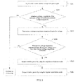
- As shown in
FIG. 1 , a method for reactive power compensation of power grid may include the following steps. - S101: The grid-tied inverter detects voltage of a power grid.
- S102: Determine whether a voltage magnitude of the detected voltage is lower than a preset normal voltage magnitude, and if yes, execute step S103; otherwise, perform no processing.
- In a power grid electricity transmission procedure, the voltage of the current power grid is detected in real time or at regular time, whether the voltage magnitude of the detected voltage is lower than the preset normal voltage magnitude is determined, and different operations are executed according to different determining results. When it is determined that the voltage magnitude of the voltage is lower than the preset normal voltage magnitude, it indicates that a voltage dip fault occurs in the power grid, and reactive power compensation processing needs to be performed; while when it is determined that the voltage magnitude of the voltage is not lower than the preset normal voltage magnitude, it indicates that the voltage of the power grid is in a normal range, and no processing is required.
- It can be understood that, the normal voltage magnitude is a boundary value between the normal state and the dip fault of the voltage of the power grid, and may be the highest magnitude corresponding to the voltage dip fault or be higher than the highest magnitude corresponding to the voltage dip fault, either of which is reasonable. Definitely, in an actual application, normal voltage magnitudes corresponding to different power grids may be different, and meanwhile, quality requirements of a power grid in different periods may be different, so the same power grid may be corresponding to different normal voltage magnitudes in different periods.
- S103: Determine the electric reference parameter corresponding to the voltage.
- When it is determined that the voltage magnitude of the voltage is lower than the preset normal voltage magnitude, that is, reactive power compensation is required because a voltage dip fault occurs in the current power grid, the electric reference parameter corresponding to the voltage may be determined, and subsequent reactive power compensation processing is performed by using the electric reference parameter corresponding to the voltage. The electric reference parameter corresponding to the voltage is the basis used to distinguish which mode of the unipolar modulation mode and the bipolar modulation mode is used, and may be: the voltage magnitude corresponding to the voltage or the voltage phase angle corresponding to the voltage. It can be understood that, in an actual application, an electric reference parameter related to the voltage may be selected according to an actual situation.
- S104: Determine a current pulse width modulation (PWM) mode according to the electric reference parameter corresponding to the voltage.
- The PWM mode may include: the unipolar modulation mode and the bipolar modulation mode.
- After the electric reference parameter corresponding to the voltage is determined, a current PWM mode may be determined, so as to perform subsequent reactive power compensation. Voltage conditions corresponding to the unipolar modulation mode and the bipolar modulation mode are different, so the electric reference parameter corresponding to the voltage may be used as the modulation basis, so as to select a modulation mode suitable for the current environment, and then effectively implement reactive power compensation.
- When the bipolar modulation mode is used for implementing reactive power compensation, no requirement is imposed on the voltage value of a current power grid, but the switching loss and the inductance loss are larger relative to those of the unipolar modulation mode; when the unipolar modulation mode is used for implementing reactive power compensation, the switching loss and the inductance loss may be smaller, but it is difficult to implement soft switching when the voltage of the power grid is low (such as the voltage of the power grid is close to the zero-crossing voltage), so that the reactive power compensation cannot be implemented. The difference between the unipolar modulation mode and the bipolar modulation mode mainly lies in whether two levels (not including the zero level) are output in the PWM modulation procedure: the unipolar modulation mode is to compare a modulation wave with a carrier, and when the modulation wave is greater than the carrier, a high level is output; otherwise, no zero level is output; the bipolar modulation mode is to compare a modulation wave with a carrier, and when the modulation wave is greater than the carrier, a high level is output; otherwise, a low level is output.
- S105: Output reactive power by using the current PWM mode, so as to implement reactive power compensation for the power grid.
- After the current PWM mode: the unipolar modulation mode or the bipolar modulation mode is determined, reactive power may be output by using the PWM mode, so as to implement reactive power compensation for the power grid.
- The basic procedure that the bipolar modulation mode and the unipolar modulation mode output the reactive power is:
- determining a reactive component of the grid-connected current according to the reactive power required for the current power grid;
- determining an active component of the grid-connected current according to active power output by the grid-tied inverter;
- determining a transient value of the grid-connected current according to the active component and the reactive component of the grid-connected current, and the voltage phase angle; and
- controlling turn-on and turn-off of a switching tube according to the unipolar modulation method and the bipolar modulation method.
- Further, in a schematic diagram of a grid-connected inverting topology shown in
FIG. 5 , Q1 and Q2 form a high-frequency bridge arm A, Q3 and Q4 form a high-frequency bridge arm B, and Q5 and Q6 form a power frequency bridge arm. The unipolar modulation procedure is: - when the voltage of the power grid Ug>0, Q5 is conducted, and Q6 is turned off;
- when the voltage of the power grid Ug<0, Q5 is turned off, and Q6 is conducted;
- when the grid-connected current ig>0, the high-frequency bridge arm A works, and the high-frequency bridge arm B is turned off; and
- when the grid-connected current ig<0, the high-frequency bridge arm A is turned off, and the high-frequency bridge arm B works.
- The bipolar modulation procedure is:
- the power frequency bridge arm is turned off; and
- the high-frequency bridge arms A and B work together.
- In the technical solution provided by the embodiments of the present invention, when the voltage magnitude of the detected voltage is lower than the preset normal voltage magnitude, the electric reference parameter corresponding to the voltage is determined, then the current PWM mode: the unipolar modulation mode or the bipolar modulation mode is determined according to the electric reference parameter corresponding to the voltage, and the reactive power is output by using the determined PWM mode, so as to implement reactive power compensation for the power grid. Compared with the existing technology, the current PWM mode is determined through the electric reference parameter corresponding to the voltage at the time of voltage dip of the power grid, so as to effectively combine the unipolar modulation mode and the bipolar modulation mode in one current period; then at the time of voltage dip of the power grid, effective reactive power compensation is performed on the power grid, and meanwhile the switching loss and the inductance loss are reduced.
- Persons skilled in the art can understand that, the current period is just the power grid period, where power grids with different frequencies are corresponding to different power grid periods. For example, the power grid period of a power grid with 50 Hz is 20 ms, namely, the current period is also 20 ms; the power grid period of a power grid with 60 Hz is 16.67 ms, namely, the current period is also 16.67 ms.
- A method for reactive power compensation of power grid provided by the present invention is introduced in combination with a specific application example below.
- It should be noted that, a method for reactive power compensation of power grid provided by the present invention is applicable to a power grid system having a grid-tied inverter. The grid-tied inverter is configured to convert direct current generated by a power generation device method into alternating current and feed the alternating current into the power grid. For example, the grid-tied inverter may be a solar grid-tied inverter, a wind energy grid-tied inverter and the like.
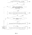
- As shown in
FIG. 2 , a method for reactive power compensation of power grid may include the following steps: - S201: A grid-tied inverter detects voltage of a power grid.
- S202: Determine whether a voltage magnitude of the detected voltage is lower than a preset normal voltage magnitude, and if yes, execute step S203; otherwise, perform no processing.
- In this embodiment, step S201 to step S202 are similar to step S101 to step
S 102 of the foregoing embodiment, so no more unnecessary details are given here. - S203: Determine a voltage magnitude corresponding to the voltage.
- When it is determined that the magnitude of the voltage of the power grid is lower than the preset normal voltage magnitude, that is, reactive power compensation is required because a voltage dip fault occurs in the current power grid, the voltage magnitude corresponding to the voltage may be determined, and subsequent reactive power compensation processing is performed by using the voltage magnitude corresponding to the voltage. The voltage magnitude corresponding to the voltage may be used as the basis for distinguishing which mode of the unipolar modulation mode and the bipolar modulation mode is used.
- S204: Determine whether the voltage magnitude corresponding to the voltage is not less than a preset voltage magnitude threshold, and if yes, execute step S205; otherwise, execute step S206.
- S205: Output reactive power by using the unipolar modulation mode.
- S206: Output reactive power by using the bipolar modulation mode.
- After the voltage magnitude corresponding to the voltage is determined, whether the voltage magnitude corresponding to the voltage is less than the preset voltage magnitude threshold may be determined, and different PWM modes are selected to implement reactive power compensation according to different determining results. When the voltage magnitude corresponding to the voltage is not less than the preset voltage magnitude threshold, the reactive power may be output by using the unipolar modulation mode, so as to have small switching loss and small inductance loss at the time of implementing reactive power compensation; while when the voltage magnitude of the voltage is less than the preset voltage magnitude threshold, the reactive power may be output by using the bipolar modulation mode, so as to implement reactive power compensation under a situation that the voltage of the power grid is low. It can be understood that, the voltage magnitude threshold is set according to the minimum voltage magnitude required for implementing soft switching by using the unipolar modulation mode. In an actual application, for different power grid demands, the voltage magnitude threshold may be set slightly higher than the minimum voltage magnitude required for implementing soft switching by using the unipolar modulation mode, or may be set as the minimum voltage magnitude required for implementing soft switching by using the unipolar modulation mode, either of which is reasonable.
- In this embodiment, when the voltage magnitude of the detected voltage is lower than the preset normal voltage magnitude, the voltage magnitude corresponding to the voltage is determined, and when the voltage magnitude corresponding to the voltage is not less than the preset voltage magnitude threshold, the unipolar modulation mode is used for implementing reactive power compensation; otherwise, the bipolar modulation mode is used for implementing reactive power compensation. Compared with the existing technology, the current PWM mode is determined through the voltage magnitude corresponding to the voltage at the time of voltage dip of the power grid, so as to effectively combine the unipolar modulation mode and the bipolar modulation mode in one current period; then at the time of voltage dip of the power grid, effective reactive power compensation is performed on the power grid, and meanwhile the switching loss and the inductance loss are reduced.
- A method for reactive power compensation of power grid provided by the present invention is introduced in combination with another specific application example below.
- It should be noted that, a method for reactive power compensation of power grid provided by the present invention is applicable to a power grid system having a grid-tied inverter. The grid-tied inverter is configured to convert direct current generated by a power generation device method into alternating current and feed the alternating current into the power grid. For example, the grid-tied inverter may be a solar grid-tied inverter, a wind energy grid-tied inverter and the like.
- As shown in
FIG. 3 , a method for reactive power compensation of power grid may include the following steps: - S301: A grid-tied inverter detects voltage of a power grid.
- S302: Determine whether a voltage magnitude of the detected voltage is lower than a preset normal voltage magnitude, and if yes, execute step S303; otherwise, perform no processing.
- In this embodiment, step S301 to step S302 are similar to step S101 to step S102 of the foregoing embodiment, so no more unnecessary details are given here.
- S303: Determine a voltage phase angle θ corresponding to the voltage.
- When it is determined that the voltage magnitude of the voltage is lower than the preset normal voltage magnitude, that is, reactive power compensation is required because a voltage dip fault occurs in the current power grid, the voltage phase angle θ corresponding to the voltage may be determined, and subsequent reactive power compensation processing is performed by using the determined voltage phase angle θ. The voltage phase angle θ may be used as the basis for distinguishing which mode of the unipolar modulation mode and the bipolar modulation mode is used.
- Persons skilled in the art can understand that, the voltage phase angle θ corresponding to the voltage is obtained by a phase locking module in the grid-tied inverter, where phase locking is an indispensable function of the grid-tied inverter. The mode of determining the voltage phase angle through the phase locking module in the grid-tied inverter is the same as that in the existing technology, so no more unnecessary details are given here.
- S304: Determine whether the voltage phase angle θ corresponding to the voltage satisfies θ 1 ≤ θ ≤ θ 2 or θ 3 ≤ θ ≤ θ 4 in one current period, and if yes, execute step S305; otherwise, execute step S306.
- S305: Output reactive power by using the unipolar modulation mode.
- S306: Output reactive power by using the bipolar modulation mode.
- After the voltage phase angle θ corresponding to the voltage is determined, whether the voltage phase angle θ corresponding to the voltage satisfies: θ 1 ≤ θ ≤ θ 2 or θ 3 ≤ θ ≤ θ 4 in one current period may be determined, and different PWM modes are selected to implement reactive power compensation according to different determining results. When the voltage phase angle θ corresponding to the voltage satisfies θ 1 ≤ θ ≤ θ 2 or θ 3 ≤ θ ≤ θ 4, the reactive power may be output by using the unipolar modulation mode, so as to have small switching loss and small inductance loss at the time of implementing reactive power compensation; otherwise, the bipolar modulation mode may be used for outputting reactive power, so as to implement reactive power compensation under a situation that the voltage of the power grid is low.

- It can be understood that, U min may be set according to the minimum voltage magnitude required for implementing soft switching by using the unipolar modulation mode. In an actual application, for different power grid demands, U min may be set slightly higher than the minimum voltage magnitude required for implementing soft switching by using the unipolar modulation mode, or may be set as the minimum voltage magnitude required for implementing soft switching by using the unipolar modulation mode, either of which is reasonable.
- A schematic diagram of area selection in unipolar and bipolar modulation modes is shown in
FIG. 4 . The waveform diagram shown in the drawing is a waveform under a situation that the voltage of the power grid is normal, Ug is the voltage of the power grid, θ is the voltage phase angle, Upeak is the voltage peak value in one current period, and U min is the minimum voltage magnitude required for implementing soft switching by using the unipolar modulation mode. According to U min,
- In this embodiment, when the voltage magnitude of the detected voltage is lower than the preset normal voltage magnitude, the voltage phase angle θ corresponding to the voltage is determined, and when the voltage phase angle θ corresponding to the voltage satisfies θ 1 ≤ θ ≤ θ 2 or θ 3 ≤ θ ≤ θ 4, the unipolar modulation mode is used for implementing reactive power compensation; otherwise, the bipolar modulation mode is used for implementing reactive power compensation. Compared with the existing technology, the current PWM mode is determined through the voltage phase angle θ corresponding to the voltage at the time of voltage dip of the power grid, so as to effectively combine the unipolar modulation mode and the bipolar modulation mode in one current period; then at the time of voltage dip of the power grid, effective reactive power compensation is performed on the power grid, and meanwhile the switching loss and the inductance loss are reduced.
- Through the description of the foregoing method embodiments, a person skilled in the art may clearly understand that the present invention may be implemented by means of software and a necessary general hardware platform, or of course, by means of a hardware, but the former is preferred in many cases. Based on such an understanding, the technical solution of the present invention essentially, or the part contributing to the prior art may be implemented in the form of a software product. The computer software product is stored in a storage medium, and includes several instructions for instructing a computer device (which may be a personal computer, a server, or a network device) to perform all or part of the steps of the methods provided in the embodiments of the present invention. The storage medium includes: any medium that can store program codes, such as a read-only Memory (ROM), a random access memory (RAM), a magnetic disk, or an optical disk.
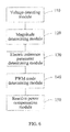
- Corresponding to the above method embodiments, an embodiment of the present invention further provides an apparatus for reactive power compensation of power grid, which, as shown in
FIG. 6 , may include: - a
voltage detecting module 110, configured to detect voltage of a power grid, and send the detected voltage to amagnitude determining module 120; - the
magnitude determining module 120, configured to determine whether a voltage magnitude of the detected voltage is lower than a preset normal voltage magnitude, and if yes, trigger an electric referenceparameter determining module 130; - the electric reference
parameter determining module 130, configured to determine an electric reference parameter corresponding to the voltage, and send the electric reference parameter corresponding to the voltage to a PWMmode determining module 140; - the PWM
mode determining module 140, configured to determine a current pulse width modulation (PWM) mode according to the electric reference parameter corresponding to the voltage, and send the current PWM mode to a reactivepower compensation module 150, where the PWM mode includes: a unipolar modulation mode and a bipolar modulation mode; and - the reactive
power compensation module 150, configured to output reactive power by using the current PWM mode, so as to implement reactive power compensation for the power grid. - In the apparatus for reactive power compensation of power grid provided by the embodiment of the present invention, when the voltage magnitude of the detected voltage is lower than the preset normal voltage magnitude, the electric reference parameter corresponding to the voltage is determined, then the current PWM mode: the unipolar modulation mode or the bipolar modulation mode is determined according to the electric reference parameter corresponding to the voltage, and the reactive power is output by using the determined PWM mode, so as to implement reactive power compensation for the power grid. Compared with the existing technology, the current PWM mode is determined through the electric reference parameter corresponding to the voltage at the time of voltage dip of the power grid, so as to effectively combine the unipolar modulation mode and the bipolar modulation mode in one current period; then at the time of voltage dip of the power grid, effective reactive power compensation is performed on the power grid, and meanwhile the switching loss and the inductance loss are reduced.
- The electric reference
parameter determining module 130 is specifically configured to determine a voltage magnitude corresponding to the voltage, and send the voltage magnitude corresponding to the voltage to a PWMmode determining module 140. - The PWM
mode determining module 140 is specifically configured to determine the unipolar modulation mode as the current PWM mode when the voltage magnitude corresponding to the voltage is not less than a preset voltage magnitude threshold; and determine the bipolar modulation mode as the current PWM mode when the voltage magnitude corresponding to the voltage is greater than the preset voltage magnitude threshold. - In another embodiment of the present invention, the electric reference
parameter determining module 130 is specifically configured to determine a voltage phase angle θ corresponding to the voltage, and send the voltage phase angle θ corresponding to the voltage to the PWMmode determining module 140. - The PWM
mode determining module 140 is specifically configured to determine the unipolar modulation mode as the current PWM mode when the voltage phase angle θ corresponding to the voltage satisfies θ 1 ≤ θ ≤ θ 2 or θ 3 ≤ θ ≤ θ 4 in one current period; and determine the bipolar modulation mode as the current PWM mode when the voltage phase angle θ corresponding to the voltage satisfies neither θ 1 ≤ θ ≤ θ 2 nor θ 3 ≤ θ ≤ θ 4 in one current period,
where
- Correspondingly, an embodiment of the present invention further provides a grid-tied inverter, including: a power management apparatus, an inverting apparatus, and any one apparatus for reactive power compensation of power grid provided by the embodiment of the present invention.
- The inverting apparatus performs active output under the control of the power management apparatus.
- The apparatus for reactive power compensation of power grid performs power grid reactive power compensation under the control of the power management apparatus.
- By using the grid-tied inverter provided by the embodiment of the present invention, the current PWM mode may be determined through the electric reference parameter corresponding to the detected voltage at the time of voltage dip of the power grid, so as to effectively combine the unipolar modulation mode and the bipolar modulation mode in one current period; then at the time of voltage dip of the power grid, effective reactive power compensation is performed on the power grid, and meanwhile the switching loss and the inductance loss are reduced.
- The apparatus or system embodiments corresponding to the method embodiments are described briefly herein because the relevant contents can be derived from the method embodiments. The described apparatus or system embodiments are merely exemplary. The units described as separate parts may or may not be physically separate, and parts displayed as units may or may not be physical units, may be located in one position, or may be distributed on multiple network elements. A part of or all of the modules may be selected according to the actual needs to achieve the objectives of the solutions of the embodiments. A person of ordinary skill in the art may understand and implement the embodiment without creative efforts.
- In the embodiments provided in the present application, it should be understood that the disclosed system, apparatus and method may be implemented in other manners without departing from the spirit and scope of the application. The current embodiments are merely exemplary examples, and should not be regarded as a limitation, and the detailed content should not limit the objective of the application. For example, the division of units or subunits is merely logic function division and can be other division in actual implementation. For example, multiple units or multiple subunits are combined together. In addition, multiple units or components may be combined or integrated in another system or some features may be ignored or not executed.
- In addition, the schematic diagrams illustrating the system, apparatus, method and different embodiments may be combined or integrated with other systems, modules, technologies or methods without departing from the scope of the present invention. In addition, the displayed or discussed mutual couplings or direct couplings or communication connections may be implemented through some interfaces. The indirect couplings or communication connections between the apparatuses or units may be implemented in electronic, mechanical or other forms.
- The foregoing descriptions are merely specific embodiments of the present invention. It should be noted by a person skilled in the art that modifications and variations may be made without departing from the principle of the invention, which should be construed as falling within the protection scope of the present invention.
Claims (8)
- A method for reactive power compensation of power grid, comprising:detecting voltage of a power grid;when a voltage magnitude of the detected voltage is lower than a preset normal voltage magnitude, determining an electric reference parameter corresponding to the voltage;determining a current pulse width modulation (PWM) mode according to the electric reference parameter corresponding to the voltage, wherein the PWM mode comprises: a unipolar modulation mode and a bipolar modulation mode; andoutputting reactive power by using the current PWM mode, so as to implement reactive power compensation for the power grid.
- The method according to claim 1, wherein the electric reference parameter corresponding to the voltage comprises: the voltage magnitude corresponding to the voltage; the determining a current pulse width modulation (PWM) mode according to the electric reference parameter specifically comprises:determining the unipolar modulation mode as the current PWM mode when the voltage magnitude corresponding to the voltage is not less than a preset voltage magnitude threshold; otherwise, determining the bipolar modulation mode as the current PWM mode.
- The method according to claim 2, wherein the voltage magnitude threshold is the minimum voltage magnitude required for implementing soft switching by using the unipolar modulation mode.
- The method according to claim 1, wherein the electric reference parameter corresponding to the voltage comprises: a voltage phase angle θ corresponding to the voltage; the determining a current pulse width modulation (PWM) mode according to the electric reference parameter specifically comprises:determining the unipolar modulation mode as the current PWM mode when the voltage phase angle θ corresponding to the voltage satisfies θ 1 ≤ θ ≤ θ 2 or θ 3 ≤ θ ≤ θ 4 in one current period; otherwise, determining the bipolar modulation mode as the current PWM mode,wherein

- An apparatus for reactive power compensation of power grid, comprising:a voltage detecting module, configured to detect voltage of a power grid, and send the detected voltage to a magnitude determining module;the magnitude determining module, configured to determine whether a voltage magnitude of the detected voltage is lower than a preset normal voltage magnitude, and if yes, trigger an electric reference parameter determining module;the electric reference parameter determining module, configured to determine an electric reference parameter corresponding to the voltage, and send the electric reference parameter corresponding to the voltage to a PWM mode determining module;the PWM mode determining module, configured to determine a current pulse width modulation (PWM) mode according to the electric reference parameter corresponding to the voltage, and send the current PWM mode to a reactive power compensation module, wherein the PWM mode comprises: a unipolar modulation mode and a bipolar modulation mode; andthe reactive power compensation module, configured to output reactive power by using the current PWM mode, so as to implement reactive power compensation for the power grid.
- The apparatus according to claim 5, wherein the electric reference parameter determining module is specifically configured to determine a voltage magnitude corresponding to the voltage, and send the voltage magnitude corresponding to the voltage to a PWM mode determining module; and
the PWM mode determining module is specifically configured to determine the unipolar modulation mode as the current PWM mode when the voltage magnitude corresponding to the voltage is not less than a preset voltage magnitude threshold; and determine the bipolar modulation mode as the current PWM mode when the voltage magnitude corresponding to the voltage is greater than the preset voltage magnitude threshold. - The apparatus according to claim 5, wherein the electric reference parameter determining module is specifically configured to determine a voltage phase angle θ corresponding to the voltage, and send the voltage phase angle θ corresponding to the voltage to the PWM mode determining module; and
the PWM mode determining module is specifically configured to determine the unipolar modulation mode as the current PWM mode when the voltage phase angle θ corresponding to the voltage satisfies θ 1 ≤ θ ≤ θ 2 or θ 3 ≤ θ ≤ θ 4 in one current period; and determine the bipolar modulation mode as the current PWM mode when the voltage phase angle θ corresponding to the voltage satisfies neither θ 1 ≤ θ ≤ θ 2 nor θ 3 ≤ θ ≤ θ 4 in one current period,
wherein
- A grid-tied inverter, comprising: a power management apparatus and an inverting apparatus, and further comprising: the apparatus for reactive power compensation of power grid according to any one of claims 5 to 7,
wherein the inverting apparatus performs active output under the control of the power management apparatus; the apparatus for reactive power compensation of power grid performs power grid reactive power compensation under the control of the power management apparatus.
Applications Claiming Priority (2)
| Application Number | Priority Date | Filing Date | Title |
|---|---|---|---|
| CN201210259515.4A CN102790399B (en) | 2012-07-25 | 2012-07-25 | Power grid reactive compensation method, device and combining inverter |
| PCT/CN2013/070975 WO2014015666A1 (en) | 2012-07-25 | 2013-01-25 | Power grid reactive compensation method and apparatus, and grid-tied inverter |
Publications (3)
| Publication Number | Publication Date |
|---|---|
| EP2731222A1 true EP2731222A1 (en) | 2014-05-14 |
| EP2731222A4 EP2731222A4 (en) | 2014-12-10 |
| EP2731222B1 EP2731222B1 (en) | 2016-07-20 |
Family
ID=47155725
Family Applications (1)
| Application Number | Title | Priority Date | Filing Date |
|---|---|---|---|
| EP13726662.3A Not-in-force EP2731222B1 (en) | 2012-07-25 | 2013-01-25 | Power grid reactive compensation method and apparatus, and grid-tied inverter |
Country Status (4)
| Country | Link |
|---|---|
| EP (1) | EP2731222B1 (en) |
| JP (1) | JP5678237B2 (en) |
| CN (1) | CN102790399B (en) |
| WO (1) | WO2014015666A1 (en) |
Cited By (1)
| Publication number | Priority date | Publication date | Assignee | Title |
|---|---|---|---|---|
| CN114336646A (en) * | 2022-01-07 | 2022-04-12 | 国网浙江省电力有限公司绍兴市上虞区供电公司 | Power distribution network reconstruction voltage control method considering intelligent soft switch |
Families Citing this family (11)
| Publication number | Priority date | Publication date | Assignee | Title |
|---|---|---|---|---|
| CN102790399B (en) * | 2012-07-25 | 2015-09-09 | 华为技术有限公司 | Power grid reactive compensation method, device and combining inverter |
| CN103166234B (en) * | 2013-03-28 | 2014-04-30 | 厦门科华恒盛股份有限公司 | Single phase grid-connected inverter reactive output control method |
| CN103368433A (en) * | 2013-07-31 | 2013-10-23 | 华为技术有限公司 | Inverter and PWM (pulse width modulation) modulation method |
| CN103580502A (en) * | 2013-11-15 | 2014-02-12 | 华为技术有限公司 | Power-switching circuit and method for controlling direct-current-alternating-current circuit |
| CN104022673B (en) * | 2014-06-26 | 2016-10-19 | 浙江昱能科技有限公司 | The SPWM modulator approach of single-phase full-bridge inverter |
| JP2017060344A (en) * | 2015-09-18 | 2017-03-23 | 株式会社日本自動車部品総合研究所 | Power converter |
| CN107591816A (en) * | 2016-07-07 | 2018-01-16 | 中兴通讯股份有限公司 | Reactive-load compensation method, device and the photovoltaic combining inverter of photovoltaic combining inverter |
| JP6666058B2 (en) * | 2016-08-16 | 2020-03-13 | 東芝三菱電機産業システム株式会社 | Grid-connected inverter device and operation method thereof |
| CN106374503B (en) | 2016-09-12 | 2018-12-07 | 珠海格力电器股份有限公司 | Voltage drop and electrical equipment grid connection processing method, device and system |
| CN111130369B (en) | 2019-12-31 | 2021-06-15 | 华为技术有限公司 | Inverter circuit control method and related device |
| CN114172166B (en) * | 2021-12-07 | 2024-11-19 | 阳光电源股份有限公司 | A voltage generating device and a high frequency generating control method thereof |
Family Cites Families (11)
| Publication number | Priority date | Publication date | Assignee | Title |
|---|---|---|---|---|
| JP2765315B2 (en) * | 1991-11-18 | 1998-06-11 | 株式会社日立製作所 | Power conversion device and control device for electric vehicle using the same |
| JP2814837B2 (en) * | 1992-06-04 | 1998-10-27 | 株式会社日立製作所 | Power converter |
| JP3413189B2 (en) * | 2002-02-20 | 2003-06-03 | 株式会社日立製作所 | Control device for pulse width modulation type inverter |
| DE10221592A1 (en) * | 2002-05-15 | 2003-12-04 | Fraunhofer Ges Forschung | Inverter and method for converting a DC electrical voltage into an AC current |
| CN100588071C (en) * | 2007-03-09 | 2010-02-03 | 中国科学院电工研究所 | Unified control method for grid-connected power generation and grid power active filtering |
| RU2392727C1 (en) * | 2009-05-07 | 2010-06-20 | Василий Сергеевич Богачев | Voltage stabilisation device |
| CN102215012B (en) * | 2011-06-07 | 2014-05-07 | 天宝电子(惠州)有限公司 | Bidirectional transformation system of solar energy and electric energy |
| DE102011051548A1 (en) * | 2011-07-04 | 2013-01-10 | Sma Solar Technology Ag | Operating procedure for an inverter and grid-fault-tolerant inverter |
| CN102437765B (en) * | 2011-10-17 | 2015-09-23 | 华为技术有限公司 | A kind of inverter topology circuit, inverse method and a kind of inverter |
| EP2595305A1 (en) * | 2011-11-21 | 2013-05-22 | Vincotech GmbH | Assymetric twin bridge DC/AC inverter capable of reactive power transfer |
| CN102790399B (en) * | 2012-07-25 | 2015-09-09 | 华为技术有限公司 | Power grid reactive compensation method, device and combining inverter |
-
2012
- 2012-07-25 CN CN201210259515.4A patent/CN102790399B/en active Active
-
2013
- 2013-01-25 WO PCT/CN2013/070975 patent/WO2014015666A1/en not_active Ceased
- 2013-01-25 JP JP2014526382A patent/JP5678237B2/en not_active Expired - Fee Related
- 2013-01-25 EP EP13726662.3A patent/EP2731222B1/en not_active Not-in-force
Cited By (1)
| Publication number | Priority date | Publication date | Assignee | Title |
|---|---|---|---|---|
| CN114336646A (en) * | 2022-01-07 | 2022-04-12 | 国网浙江省电力有限公司绍兴市上虞区供电公司 | Power distribution network reconstruction voltage control method considering intelligent soft switch |
Also Published As
| Publication number | Publication date |
|---|---|
| EP2731222B1 (en) | 2016-07-20 |
| CN102790399A (en) | 2012-11-21 |
| JP5678237B2 (en) | 2015-02-25 |
| EP2731222A4 (en) | 2014-12-10 |
| CN102790399B (en) | 2015-09-09 |
| WO2014015666A1 (en) | 2014-01-30 |
| JP2014522633A (en) | 2014-09-04 |
Similar Documents
| Publication | Publication Date | Title |
|---|---|---|
| EP2731222B1 (en) | Power grid reactive compensation method and apparatus, and grid-tied inverter | |
| US11791632B2 (en) | High-frequency uncontrolled rectifier-based DC transmission system for offshore wind farm | |
| Zeng et al. | Coordinated control of multi‐functional grid‐tied inverters using conductance and susceptance limitation | |
| EP3285350B1 (en) | Cascaded photovoltaic grid-connected inverter, control method and control device for the same | |
| US20180166883A1 (en) | Low voltage ride-through control system and method for multi-inverter grid-connected power converter | |
| Papanikolaou | Low‐voltage ride‐through concept in flyback inverter‐based alternating current–photovoltaic modules | |
| Jalilian et al. | DC‐link fault current limiter‐based fault ride‐through scheme for inverter‐based distributed generation | |
| EP2555405B1 (en) | Converter, motor driving module, and refrigerating apparatus | |
| EP4283816A1 (en) | Control method and system for island operation of vsc-hvdc system | |
| EP3026775B1 (en) | Control device for solar power generation inverter | |
| CN104022527B (en) | Direct current micro-grid system | |
| CN104578886B (en) | A kind of three-level photovoltaic inverter pulse duration modulation method and modulator | |
| EP2541721A2 (en) | Grid-connected power conversion device | |
| Dhar et al. | Adaptive threshold based new active islanding protection scheme for multiple PV based microgrid application | |
| CN102891503A (en) | Grid-connected startup method for photovoltaic grid-connected inverter | |
| He et al. | Low‐voltage ride‐through control for photovoltaic generation in the low‐voltage distribution network | |
| CN103219739B (en) | Emergent power supporting control method | |
| CN104485825B (en) | Single-phase programmable current source device and control method thereof | |
| EP4075629A1 (en) | High-low voltage continuous ride-through control method and system for permanent magnet direct-drive wind power generating set | |
| CN106998063B (en) | An Active Suppression System for Submerged Current in Half-wavelength AC Transmission Lines | |
| CN105633998A (en) | Wind generating set high-voltage crossing control method and device | |
| Mousavi et al. | Fault ride through enhancement of large‐scale solar plants using distributed converters | |
| Zhang et al. | Uniform carrier‐based PWM method for three‐phase three‐level three‐wire and four‐wire converter system with neutral‐point balancing | |
| Liu et al. | The control strategy for Hybrid HVDC using voltage margin control and voltage dependent current order limiter control | |
| EP4593277A1 (en) | Power conversion system and ripple current suppression method therefor |
Legal Events
| Date | Code | Title | Description |
|---|---|---|---|
| PUAI | Public reference made under article 153(3) epc to a published international application that has entered the european phase |
Free format text: ORIGINAL CODE: 0009012 |
|
| 17P | Request for examination filed |
Effective date: 20130613 |
|
| AK | Designated contracting states |
Kind code of ref document: A1 Designated state(s): AL AT BE BG CH CY CZ DE DK EE ES FI FR GB GR HR HU IE IS IT LI LT LU LV MC MK MT NL NO PL PT RO RS SE SI SK SM TR |
|
| A4 | Supplementary search report drawn up and despatched |
Effective date: 20141112 |
|
| RIC1 | Information provided on ipc code assigned before grant |
Ipc: H02M 7/48 20070101ALI20141106BHEP Ipc: H02J 3/18 20060101AFI20141106BHEP |
|
| DAX | Request for extension of the european patent (deleted) | ||
| GRAP | Despatch of communication of intention to grant a patent |
Free format text: ORIGINAL CODE: EPIDOSNIGR1 |
|
| INTG | Intention to grant announced |
Effective date: 20160204 |
|
| GRAS | Grant fee paid |
Free format text: ORIGINAL CODE: EPIDOSNIGR3 |
|
| GRAA | (expected) grant |
Free format text: ORIGINAL CODE: 0009210 |
|
| AK | Designated contracting states |
Kind code of ref document: B1 Designated state(s): AL AT BE BG CH CY CZ DE DK EE ES FI FR GB GR HR HU IE IS IT LI LT LU LV MC MK MT NL NO PL PT RO RS SE SI SK SM TR |
|
| REG | Reference to a national code |
Ref country code: GB Ref legal event code: FG4D |
|
| REG | Reference to a national code |
Ref country code: CH Ref legal event code: EP |
|
| REG | Reference to a national code |
Ref country code: IE Ref legal event code: FG4D |
|
| REG | Reference to a national code |
Ref country code: AT Ref legal event code: REF Ref document number: 814769 Country of ref document: AT Kind code of ref document: T Effective date: 20160815 |
|
| REG | Reference to a national code |
Ref country code: DE Ref legal event code: R096 Ref document number: 602013009613 Country of ref document: DE |
|
| REG | Reference to a national code |
Ref country code: LT Ref legal event code: MG4D |
|
| REG | Reference to a national code |
Ref country code: NL Ref legal event code: MP Effective date: 20160720 |
|
| REG | Reference to a national code |
Ref country code: AT Ref legal event code: MK05 Ref document number: 814769 Country of ref document: AT Kind code of ref document: T Effective date: 20160720 |
|
| PG25 | Lapsed in a contracting state [announced via postgrant information from national office to epo] |
Ref country code: HR Free format text: LAPSE BECAUSE OF FAILURE TO SUBMIT A TRANSLATION OF THE DESCRIPTION OR TO PAY THE FEE WITHIN THE PRESCRIBED TIME-LIMIT Effective date: 20160720 Ref country code: NL Free format text: LAPSE BECAUSE OF FAILURE TO SUBMIT A TRANSLATION OF THE DESCRIPTION OR TO PAY THE FEE WITHIN THE PRESCRIBED TIME-LIMIT Effective date: 20160720 Ref country code: NO Free format text: LAPSE BECAUSE OF FAILURE TO SUBMIT A TRANSLATION OF THE DESCRIPTION OR TO PAY THE FEE WITHIN THE PRESCRIBED TIME-LIMIT Effective date: 20161020 Ref country code: LT Free format text: LAPSE BECAUSE OF FAILURE TO SUBMIT A TRANSLATION OF THE DESCRIPTION OR TO PAY THE FEE WITHIN THE PRESCRIBED TIME-LIMIT Effective date: 20160720 Ref country code: IS Free format text: LAPSE BECAUSE OF FAILURE TO SUBMIT A TRANSLATION OF THE DESCRIPTION OR TO PAY THE FEE WITHIN THE PRESCRIBED TIME-LIMIT Effective date: 20161120 Ref country code: FI Free format text: LAPSE BECAUSE OF FAILURE TO SUBMIT A TRANSLATION OF THE DESCRIPTION OR TO PAY THE FEE WITHIN THE PRESCRIBED TIME-LIMIT Effective date: 20160720 Ref country code: RS Free format text: LAPSE BECAUSE OF FAILURE TO SUBMIT A TRANSLATION OF THE DESCRIPTION OR TO PAY THE FEE WITHIN THE PRESCRIBED TIME-LIMIT Effective date: 20160720 Ref country code: IT Free format text: LAPSE BECAUSE OF FAILURE TO SUBMIT A TRANSLATION OF THE DESCRIPTION OR TO PAY THE FEE WITHIN THE PRESCRIBED TIME-LIMIT Effective date: 20160720 |
|
| PG25 | Lapsed in a contracting state [announced via postgrant information from national office to epo] |
Ref country code: LV Free format text: LAPSE BECAUSE OF FAILURE TO SUBMIT A TRANSLATION OF THE DESCRIPTION OR TO PAY THE FEE WITHIN THE PRESCRIBED TIME-LIMIT Effective date: 20160720 Ref country code: SE Free format text: LAPSE BECAUSE OF FAILURE TO SUBMIT A TRANSLATION OF THE DESCRIPTION OR TO PAY THE FEE WITHIN THE PRESCRIBED TIME-LIMIT Effective date: 20160720 Ref country code: ES Free format text: LAPSE BECAUSE OF FAILURE TO SUBMIT A TRANSLATION OF THE DESCRIPTION OR TO PAY THE FEE WITHIN THE PRESCRIBED TIME-LIMIT Effective date: 20160720 Ref country code: BE Free format text: LAPSE BECAUSE OF FAILURE TO SUBMIT A TRANSLATION OF THE DESCRIPTION OR TO PAY THE FEE WITHIN THE PRESCRIBED TIME-LIMIT Effective date: 20160720 Ref country code: GR Free format text: LAPSE BECAUSE OF FAILURE TO SUBMIT A TRANSLATION OF THE DESCRIPTION OR TO PAY THE FEE WITHIN THE PRESCRIBED TIME-LIMIT Effective date: 20161021 Ref country code: AT Free format text: LAPSE BECAUSE OF FAILURE TO SUBMIT A TRANSLATION OF THE DESCRIPTION OR TO PAY THE FEE WITHIN THE PRESCRIBED TIME-LIMIT Effective date: 20160720 Ref country code: PT Free format text: LAPSE BECAUSE OF FAILURE TO SUBMIT A TRANSLATION OF THE DESCRIPTION OR TO PAY THE FEE WITHIN THE PRESCRIBED TIME-LIMIT Effective date: 20161121 Ref country code: PL Free format text: LAPSE BECAUSE OF FAILURE TO SUBMIT A TRANSLATION OF THE DESCRIPTION OR TO PAY THE FEE WITHIN THE PRESCRIBED TIME-LIMIT Effective date: 20160720 |
|
| REG | Reference to a national code |
Ref country code: DE Ref legal event code: R097 Ref document number: 602013009613 Country of ref document: DE |
|
| PG25 | Lapsed in a contracting state [announced via postgrant information from national office to epo] |
Ref country code: RO Free format text: LAPSE BECAUSE OF FAILURE TO SUBMIT A TRANSLATION OF THE DESCRIPTION OR TO PAY THE FEE WITHIN THE PRESCRIBED TIME-LIMIT Effective date: 20160720 Ref country code: EE Free format text: LAPSE BECAUSE OF FAILURE TO SUBMIT A TRANSLATION OF THE DESCRIPTION OR TO PAY THE FEE WITHIN THE PRESCRIBED TIME-LIMIT Effective date: 20160720 |
|
| PLBE | No opposition filed within time limit |
Free format text: ORIGINAL CODE: 0009261 |
|
| STAA | Information on the status of an ep patent application or granted ep patent |
Free format text: STATUS: NO OPPOSITION FILED WITHIN TIME LIMIT |
|
| PG25 | Lapsed in a contracting state [announced via postgrant information from national office to epo] |
Ref country code: DK Free format text: LAPSE BECAUSE OF FAILURE TO SUBMIT A TRANSLATION OF THE DESCRIPTION OR TO PAY THE FEE WITHIN THE PRESCRIBED TIME-LIMIT Effective date: 20160720 Ref country code: SM Free format text: LAPSE BECAUSE OF FAILURE TO SUBMIT A TRANSLATION OF THE DESCRIPTION OR TO PAY THE FEE WITHIN THE PRESCRIBED TIME-LIMIT Effective date: 20160720 Ref country code: BG Free format text: LAPSE BECAUSE OF FAILURE TO SUBMIT A TRANSLATION OF THE DESCRIPTION OR TO PAY THE FEE WITHIN THE PRESCRIBED TIME-LIMIT Effective date: 20161020 Ref country code: SK Free format text: LAPSE BECAUSE OF FAILURE TO SUBMIT A TRANSLATION OF THE DESCRIPTION OR TO PAY THE FEE WITHIN THE PRESCRIBED TIME-LIMIT Effective date: 20160720 Ref country code: CZ Free format text: LAPSE BECAUSE OF FAILURE TO SUBMIT A TRANSLATION OF THE DESCRIPTION OR TO PAY THE FEE WITHIN THE PRESCRIBED TIME-LIMIT Effective date: 20160720 |
|
| 26N | No opposition filed |
Effective date: 20170421 |
|
| PG25 | Lapsed in a contracting state [announced via postgrant information from national office to epo] |
Ref country code: SI Free format text: LAPSE BECAUSE OF FAILURE TO SUBMIT A TRANSLATION OF THE DESCRIPTION OR TO PAY THE FEE WITHIN THE PRESCRIBED TIME-LIMIT Effective date: 20160720 |
|
| REG | Reference to a national code |
Ref country code: CH Ref legal event code: PL |
|
| GBPC | Gb: european patent ceased through non-payment of renewal fee |
Effective date: 20170125 |
|
| PG25 | Lapsed in a contracting state [announced via postgrant information from national office to epo] |
Ref country code: MC Free format text: LAPSE BECAUSE OF FAILURE TO SUBMIT A TRANSLATION OF THE DESCRIPTION OR TO PAY THE FEE WITHIN THE PRESCRIBED TIME-LIMIT Effective date: 20160720 |
|
| REG | Reference to a national code |
Ref country code: FR Ref legal event code: ST Effective date: 20170929 |
|
| PG25 | Lapsed in a contracting state [announced via postgrant information from national office to epo] |
Ref country code: LI Free format text: LAPSE BECAUSE OF NON-PAYMENT OF DUE FEES Effective date: 20170131 Ref country code: FR Free format text: LAPSE BECAUSE OF NON-PAYMENT OF DUE FEES Effective date: 20170131 Ref country code: CH Free format text: LAPSE BECAUSE OF NON-PAYMENT OF DUE FEES Effective date: 20170131 |
|
| REG | Reference to a national code |
Ref country code: IE Ref legal event code: MM4A |
|
| PG25 | Lapsed in a contracting state [announced via postgrant information from national office to epo] |
Ref country code: GB Free format text: LAPSE BECAUSE OF NON-PAYMENT OF DUE FEES Effective date: 20170125 Ref country code: LU Free format text: LAPSE BECAUSE OF NON-PAYMENT OF DUE FEES Effective date: 20170125 |
|
| PG25 | Lapsed in a contracting state [announced via postgrant information from national office to epo] |
Ref country code: IE Free format text: LAPSE BECAUSE OF NON-PAYMENT OF DUE FEES Effective date: 20170125 |
|
| PG25 | Lapsed in a contracting state [announced via postgrant information from national office to epo] |
Ref country code: MT Free format text: LAPSE BECAUSE OF NON-PAYMENT OF DUE FEES Effective date: 20170125 |
|
| PG25 | Lapsed in a contracting state [announced via postgrant information from national office to epo] |
Ref country code: AL Free format text: LAPSE BECAUSE OF FAILURE TO SUBMIT A TRANSLATION OF THE DESCRIPTION OR TO PAY THE FEE WITHIN THE PRESCRIBED TIME-LIMIT Effective date: 20160720 |
|
| PG25 | Lapsed in a contracting state [announced via postgrant information from national office to epo] |
Ref country code: HU Free format text: LAPSE BECAUSE OF FAILURE TO SUBMIT A TRANSLATION OF THE DESCRIPTION OR TO PAY THE FEE WITHIN THE PRESCRIBED TIME-LIMIT; INVALID AB INITIO Effective date: 20130125 |
|
| PG25 | Lapsed in a contracting state [announced via postgrant information from national office to epo] |
Ref country code: CY Free format text: LAPSE BECAUSE OF NON-PAYMENT OF DUE FEES Effective date: 20160720 |
|
| PG25 | Lapsed in a contracting state [announced via postgrant information from national office to epo] |
Ref country code: MK Free format text: LAPSE BECAUSE OF FAILURE TO SUBMIT A TRANSLATION OF THE DESCRIPTION OR TO PAY THE FEE WITHIN THE PRESCRIBED TIME-LIMIT Effective date: 20160720 |
|
| PG25 | Lapsed in a contracting state [announced via postgrant information from national office to epo] |
Ref country code: TR Free format text: LAPSE BECAUSE OF FAILURE TO SUBMIT A TRANSLATION OF THE DESCRIPTION OR TO PAY THE FEE WITHIN THE PRESCRIBED TIME-LIMIT Effective date: 20160720 |
|
| REG | Reference to a national code |
Ref country code: DE Ref legal event code: R081 Ref document number: 602013009613 Country of ref document: DE Owner name: HUAWEI DIGITAL POWER TECHNOLOGIES CO., LTD., S, CN Free format text: FORMER OWNER: HUAWEI TECHNOLOGIES CO., LTD., SHENZHEN, GUANGDONG, CN |
|
| P01 | Opt-out of the competence of the unified patent court (upc) registered |
Effective date: 20230524 |
|
| PGFP | Annual fee paid to national office [announced via postgrant information from national office to epo] |
Ref country code: DE Payment date: 20231205 Year of fee payment: 12 |
|
| REG | Reference to a national code |
Ref country code: DE Ref legal event code: R119 Ref document number: 602013009613 Country of ref document: DE |
|
| PG25 | Lapsed in a contracting state [announced via postgrant information from national office to epo] |
Ref country code: DE Free format text: LAPSE BECAUSE OF NON-PAYMENT OF DUE FEES Effective date: 20250801 |