EP2731193B1 - Space borne antenna system - Google Patents
Space borne antenna system Download PDFInfo
- Publication number
- EP2731193B1 EP2731193B1 EP12007610.4A EP12007610A EP2731193B1 EP 2731193 B1 EP2731193 B1 EP 2731193B1 EP 12007610 A EP12007610 A EP 12007610A EP 2731193 B1 EP2731193 B1 EP 2731193B1
- Authority
- EP
- European Patent Office
- Prior art keywords
- antenna
- boom
- platform
- radiating element
- feed arrangement
- Prior art date
- Legal status (The legal status is an assumption and is not a legal conclusion. Google has not performed a legal analysis and makes no representation as to the accuracy of the status listed.)
- Active
Links
Images



Classifications
-
- H—ELECTRICITY
- H01—ELECTRIC ELEMENTS
- H01Q—ANTENNAS, i.e. RADIO AERIALS
- H01Q1/00—Details of, or arrangements associated with, antennas
- H01Q1/12—Supports; Mounting means
- H01Q1/1207—Supports; Mounting means for fastening a rigid aerial element
- H01Q1/1228—Supports; Mounting means for fastening a rigid aerial element on a boom
-
- H—ELECTRICITY
- H01—ELECTRIC ELEMENTS
- H01Q—ANTENNAS, i.e. RADIO AERIALS
- H01Q1/00—Details of, or arrangements associated with, antennas
- H01Q1/27—Adaptation for use in or on movable bodies
- H01Q1/28—Adaptation for use in or on aircraft, missiles, satellites, or balloons
- H01Q1/288—Satellite antennas
-
- H—ELECTRICITY
- H01—ELECTRIC ELEMENTS
- H01Q—ANTENNAS, i.e. RADIO AERIALS
- H01Q19/00—Combinations of primary active antenna elements and units with secondary devices, e.g. with quasi-optical devices, for giving the antenna a desired directional characteristic
- H01Q19/10—Combinations of primary active antenna elements and units with secondary devices, e.g. with quasi-optical devices, for giving the antenna a desired directional characteristic using reflecting surfaces
- H01Q19/104—Combinations of primary active antenna elements and units with secondary devices, e.g. with quasi-optical devices, for giving the antenna a desired directional characteristic using reflecting surfaces using a substantially flat reflector for deflecting the radiated beam, e.g. periscopic antennas
-
- H—ELECTRICITY
- H01—ELECTRIC ELEMENTS
- H01Q—ANTENNAS, i.e. RADIO AERIALS
- H01Q19/00—Combinations of primary active antenna elements and units with secondary devices, e.g. with quasi-optical devices, for giving the antenna a desired directional characteristic
- H01Q19/10—Combinations of primary active antenna elements and units with secondary devices, e.g. with quasi-optical devices, for giving the antenna a desired directional characteristic using reflecting surfaces
- H01Q19/18—Combinations of primary active antenna elements and units with secondary devices, e.g. with quasi-optical devices, for giving the antenna a desired directional characteristic using reflecting surfaces having two or more spaced reflecting surfaces
- H01Q19/19—Combinations of primary active antenna elements and units with secondary devices, e.g. with quasi-optical devices, for giving the antenna a desired directional characteristic using reflecting surfaces having two or more spaced reflecting surfaces comprising one main concave reflecting surface associated with an auxiliary reflecting surface
-
- H—ELECTRICITY
- H01—ELECTRIC ELEMENTS
- H01Q—ANTENNAS, i.e. RADIO AERIALS
- H01Q3/00—Arrangements for changing or varying the orientation or the shape of the directional pattern of the waves radiated from an antenna or antenna system
- H01Q3/26—Arrangements for changing or varying the orientation or the shape of the directional pattern of the waves radiated from an antenna or antenna system varying the relative phase or relative amplitude of energisation between two or more active radiating elements; varying the distribution of energy across a radiating aperture
- H01Q3/2658—Phased-array fed focussing structure
Definitions
- the invention relates to a space borne antenna system.
- the invention relates to a multiple antenna system for space borne applications like radar, synthetic aperture radar (SAR), interferometric SAR or moving target indication (MTI).
- SAR synthetic aperture radar
- MTI moving target indication
- Known antenna systems for example an interferometric SAR instrument, often comprise two or more radiating apertures (i.e. antenna arrangements) which are mounted on a single platform, e.g. a spacecraft or a satellite, with a certain spatial sensor separation.
- a large separation, i.e. baseline, between the radiating apertures is reached by mounting at least one of the antennas on the tip of a boom like structure.
- the boom like structure e.g. arm or mast
- the boom has to be adapted to have a sufficient, predetermined stiffness.
- this may result in a heavy and mechanically complex boom.
- the distance between platform and antenna may influence the performance of the antenna system.
- US 6 424 314 B1 discloses a support for a deployable reflector for use on a modular satellite antenna assembly being constructed of an elongated boom supported at both ends by a pair of two axis actuators.
- the boom is attached at its inboard end to the satellite structure in close proximity to the point of attachment of the associated signal feed assembly to minimize the differential thermal stress throughout the antenna assembly.
- EP 1 119 072 A2 discloses a method and apparatus for producing contiguous spot beam communications coverage on the Earth's surface.
- the apparatus comprises an antenna system including two wide scan antennas and two narrow scan antennas.
- the two wide scan antennas are disposed substantially opposite each other, and the two narrow scan antennas are disposed substantially opposite each other and substantially normal to the wide scan antennas.
- the first wide scan antenna, second wide scan antenna, and first narrow scan antenna produce a first beam pattern on a planetary surface and the first wide scan antenna, second wide scan antenna, and second narrow scan antenna produce a second beam pattern on the planetary surface.
- D.M. Simpson "The Qualcomm Family” discloses spacecraft configuration called “Snapdragon” being a repackaging of existing hardware on a new structure.
- the invention is based on the consideration that separation of the feed arrangement and the radiation element enables a more performing antenna system.
- the reason for the better performance is the fact that no cables between the platform and the tip of the boom have to be installed.
- the signals In known antenna systems, for the exchange of control commandos or RF signals between the platform and an antenna being arranged on the tip of the boom, the signals have to be routed along the boom by cables or waveguides which is complex. RF signal quality suffers from losses due to cable or waveguide length.
- no calibration effort and thermal control of the antennas remote from the platform is necessary.
- the first radiating element may be adapted to receive electromagnetic waves from the first feed arrangement and to redirect them in a different direction.
- this first antenna arrangement represents a transmit (Tx) antenna.
- the first radiating element may be adapted to receive electromagnetic waves and to redirect them in a different direction to the first feed arrangement.
- the first antenna arrangement is adapted to be a receive (Rx) antenna.
- the first radiating element may be adapted to receive electromagnetic waves from the first feed arrangement and to redirect them in a different direction and to receive electromagnetic waves from the different direction and to redirect them to the first feed arrangement.
- this first antenna arrangement represents a receive and transmit (Rx/Tx) antenna.
- the first radiating element can comprise a flat reflector, such as a reflecting plane, or a reflector or a reflect-array.
- the radiating elements can be passive elements having a predetermined shape and reflecting properties according to a desired signal beam deflection.
- the first feed arrangement comprises a first secondary antenna that can comprise at least one reflector antenna or reflect-array antenna or antenna elements.
- the first secondary antenna system can comprise a feed system and one or more reflectors or one and more reflect-arrays.
- the feed system may comprise one or more antenna elements.
- the first feed arrangement is realized as focusing secondary antenna for the first radiating element. It may comprise of at least one ore more reflector antennas or reflect-array antennas. Likewise, the first feed arrangement may comprise at least one reflector antenna system, comprising or consisting of at least one or more feed elements and a one ore more reflectors. The first feed arrangement may alternatively comprise at least one reflect-array antenna system, comprising or consisting of one or more feed elements and one or more reflect-arrays. Hence, electromagnetic waves may be deflected by or within the feed arrangement. In such an antenna system, multiple antenna elements in the feed system may be used for beam squint in any direction. Likewise, one or more first secondary antennas may be used for beam squint in any direction.
- An example for the first secondary antenna with more than one reflector comprises a cassegrain like secondary (hyperbolic) reflector which is illuminated with at least one focusing (parabolic) ternary reflector which is illuminated by a feed system with one or more antenna elements.
- the first boom is a deployable or extractable structure (e.g. a mast or telescopic arm) with arbitrary shape and configuration.
- the shape and the configuration of the boom may be arbitrary, since it is not essential for the current invention as long as there is a baseline, i.e. distance, between the first feed arrangement and a corresponding first radiating element.
- a further antenna or antenna system (in other words: an antenna arrangement) is arranged on or close to the platform, wherein the antenna or antenna system is adapted for reception and/or transmission of electromagnetic waves.
- the antenna system according to the invention comprises more than one antenna arrangements.
- the further antenna arranged on or close to the platform may be used as a receive antenna, while the first antenna arrangement which has a respective first radiating element mounted at the tip of the first boom is a transmit antenna.
- the antenna system according to the invention further comprises a second antenna arrangement with the same features as the first antenna arrangement. In case the first and the second antenna arrangements are operating as transmit antennas, the antenna system may be used as an interferometric SAR antenna system.
- An advantage of the antenna system according to the invention is that the radiating elements can be realized passive, i.e. no RF signals need to be routed along the boom(s) being connected to the platform.
- the weight of the passive radiating element at the end of the boom is low. This approach avoids laying RF waveguides along the deployable boom, and minimizes calibration efforts and electrical losses in these waveguides.
- a further advantage of the proposed antenna system is that the feed system and its assigned electronics are mounted in close vicinity of the platform or directly into the platform where they are under tight thermal control.
- the principle advantage is that the proposed feed system allows architectures with very long boom (boom length >> diameter of reflecting element at tip of boom) as the first secondary antenna illuminates the first radiating element.
- Tx transmit
- Rx receive
- Fig. 1 shows a first example of a known space borne antenna system.
- the antenna system comprises a platform 10, a boom 20, a feed system 30 and a passive radiating element 40a.
- the platform 10 may be, for example, a satellite or a spacecraft.
- the boom 20 can be, for example, a mast or a telescopic arm.
- the boom 20 comprises a first end 21 and a second end 22. While the first end 21 is attached to the platform 10, the second end 22 which constitutes a tip of the boom 20 bears the radiating element 40a. This means, the radiating element 40a is mounted at the tip of the boom.
- the radiating element 40a is a flat reflector, such as a reflecting plane, or a reflect-array which typically have a surface which is within one plane.
- the feed system 30 is arranged on or close to the platform 10.
- the feed system 30 may comprise one or more antenna elements.
- the combination of feed system 30 and radiating element 40a is called an antenna arrangement.
- An electronics or control unit of the feed system 30 which is not shown in the figures can be mounted in close vicinity of the platform 10 or directly into the platform 10.
- the feed system 30 and the radiating element 40a are arranged such that the radiating element 40a can receive electromagnetic waves from the feed system 30 and redirect them in a different direction (beam direction 50).
- the antenna arrangement constitutes a transmit (Tx) antenna.
- the antenna arrangement could be realized such that electromagnetic waves received by the radiating element 40a may be directed to the feed system to constitute a receive (Rx) antenna.
- the antenna system may be adapted to both receive and transmit electromagnetic waves, such that the antenna system constitutes a receive and transmit antenna.
- Fig. 2 shows a second known example of a space borne antenna system which differs from the example of Fig. 1 only in that, that the passive radiating element is a reflector 40b which may have a concave surface.
- the reflector may be a parabolic reflector or of any other shape.
- the feed arrangement is a secondary antenna 44 consisting of a reflector 43 and a feed system 30 directed to the reflector or reflect-array.
- the feed system 30 may comprise one or more antenna elements.
- the reflector 43 may be realized alternatively as reflect-array.
- the reflector 40b (or alternatively flat reflector, e.g. reflecting plane or reflect-array) at the tip of the boom 20 constitutes a primary antenna and the antenna 44 a secondary antenna.
- the primary antenna 42 on the tip of the boom receives electromagnetic waves from the secondary antenna 44 and forwards them in the direction of intention (beam direction 50).
- the primary antenna element 42 receives electromagnetic waves from the beam direction 50 and directs them in the direction of the secondary antenna 44.
- Providing a feed arrangement on or close to the platform 10 and the first end 21 of the boom, respectively, and a radiating element at the second end 22 of the boom 20 ensures that no RF (radio frequency) signals need to be routed along the boom via cables or waveguides. This approach avoids laying RF waveguides along the fixed or deployable boom, and minimizes calibration efforts and electrical losses in these waveguides.
- An antenna system comprises two antenna arrangements.
- the first antenna arrangement comprises a first boom 20-1, a first passive radiating element 40b-1 (constituting a first primary antenna 42-1) at the tip of the first boom 20-1 and a first feed arrangement (i.e. first secondary antenna 44-1) close to or arranged in the platform 10.
- the second antenna arrangement comprises a second boom 20-2, a second passive radiating element 40b-2 (constituting a second primary antenna 42-2) at the tip of the second boom 20-2 and a second feed arrangement (i.e. a second secondary antenna 44-2) close to or arranged in the platform 10.
- the first and second booms 20-1 and 20-2 are arranged on opposite sides of the platform 10.
- a baseline (distance) between the two radiators 40b-1 and 40b-2 is depicted with 60.
- Both feed arrangements consist of a reflecting element 43-1 and 43-2 as well as a feed system 30-1 and 30-2.
- one of the antenna arrangements may be used as transmit (Tx) antenna while the other antenna arrangement may be used as receive (Rx) antenna.
- at least one of the antenna arrangements might be adapted to be a receive and transmit antenna.
- the embodiment of an antenna system according to the invention is based on the fourth example illustrated in Fig. 4 .
- a further antenna 70 is mounted on or in close vicinity to the platform 10.
- the antenna 70 comprises a reflector or reflect-array 72 and a feed system 71. While the further antenna 70 is adapted to receive electromagnetic waves (receive Rx antenna), the two other antenna arrangements are configured to transmit electromagnetic waves (transmit Tx antennas). Alternatively, receive and transmit direction might be interchanged between the antenna arrangements.
- An antenna system as illustrated in Figs. 4 and 5 may be used as across track and/or along track interferometric SAR.
Landscapes
- Physics & Mathematics (AREA)
- Engineering & Computer Science (AREA)
- Astronomy & Astrophysics (AREA)
- General Physics & Mathematics (AREA)
- Remote Sensing (AREA)
- Aviation & Aerospace Engineering (AREA)
- Aerials With Secondary Devices (AREA)
- Variable-Direction Aerials And Aerial Arrays (AREA)
Description
- The invention relates to a space borne antenna system. In particular, the invention relates to a multiple antenna system for space borne applications like radar, synthetic aperture radar (SAR), interferometric SAR or moving target indication (MTI).
- Known antenna systems, for example an interferometric SAR instrument, often comprise two or more radiating apertures (i.e. antenna arrangements) which are mounted on a single platform, e.g. a spacecraft or a satellite, with a certain spatial sensor separation. A large separation, i.e. baseline, between the radiating apertures is reached by mounting at least one of the antennas on the tip of a boom like structure. The boom like structure (e.g. arm or mast) may be fixed or deployable. According to the partly high weight of the antenna mounted at the tip of the boom, the boom has to be adapted to have a sufficient, predetermined stiffness. However, this may result in a heavy and mechanically complex boom. Furthermore, the distance between platform and antenna may influence the performance of the antenna system.
-
US 6 424 314 B1 discloses a support for a deployable reflector for use on a modular satellite antenna assembly being constructed of an elongated boom supported at both ends by a pair of two axis actuators. The boom is attached at its inboard end to the satellite structure in close proximity to the point of attachment of the associated signal feed assembly to minimize the differential thermal stress throughout the antenna assembly. - Ludwig M et al: "Imaging Ka-band SAR interferometer" discloses a study into the feasibility of an interferometric Ka-Band SAR instrument with high resolution capabilities.
-
EP 1 119 072 A2 discloses a method and apparatus for producing contiguous spot beam communications coverage on the Earth's surface. The apparatus comprises an antenna system including two wide scan antennas and two narrow scan antennas. The two wide scan antennas are disposed substantially opposite each other, and the two narrow scan antennas are disposed substantially opposite each other and substantially normal to the wide scan antennas. The first wide scan antenna, second wide scan antenna, and first narrow scan antenna produce a first beam pattern on a planetary surface and the first wide scan antenna, second wide scan antenna, and second narrow scan antenna produce a second beam pattern on the planetary surface. - D.M. Simpson: "The Snapdragon Family" discloses spacecraft configuration called "Snapdragon" being a repackaging of existing hardware on a new structure.
- It is therefore an object of the present invention to provide a space borne antenna system which is structural and/or functional improved.
- This object is solved by an antenna system according to the features of claim 1. Preferred embodiments are set out in the dependent claims.
- The invention is based on the consideration that separation of the feed arrangement and the radiation element enables a more performing antenna system. The reason for the better performance is the fact that no cables between the platform and the tip of the boom have to be installed. In known antenna systems, for the exchange of control commandos or RF signals between the platform and an antenna being arranged on the tip of the boom, the signals have to be routed along the boom by cables or waveguides which is complex. RF signal quality suffers from losses due to cable or waveguide length. Furthermore, in contrast to the known antenna systems, no calibration effort and thermal control of the antennas remote from the platform is necessary.
- In the antenna system according to the invention, the first radiating element may be adapted to receive electromagnetic waves from the first feed arrangement and to redirect them in a different direction. Hence this first antenna arrangement represents a transmit (Tx) antenna. Alternatively, the first radiating element may be adapted to receive electromagnetic waves and to redirect them in a different direction to the first feed arrangement. In this case the first antenna arrangement is adapted to be a receive (Rx) antenna. Furthermore, the first radiating element may be adapted to receive electromagnetic waves from the first feed arrangement and to redirect them in a different direction and to receive electromagnetic waves from the different direction and to redirect them to the first feed arrangement. Hence, this first antenna arrangement represents a receive and transmit (Rx/Tx) antenna.
- The first radiating element can comprise a flat reflector, such as a reflecting plane, or a reflector or a reflect-array.
- The radiating elements can be passive elements having a predetermined shape and reflecting properties according to a desired signal beam deflection.
- The first feed arrangement comprises a first secondary antenna that can comprise at least one reflector antenna or reflect-array antenna or antenna elements.
- The first secondary antenna system can comprise a feed system and one or more reflectors or one and more reflect-arrays. The feed system may comprise one or more antenna elements.
- In other words, according to this invention the first feed arrangement is realized as focusing secondary antenna for the first radiating element. It may comprise of at least one ore more reflector antennas or reflect-array antennas. Likewise, the first feed arrangement may comprise at least one reflector antenna system, comprising or consisting of at least one or more feed elements and a one ore more reflectors. The first feed arrangement may alternatively comprise at least one reflect-array antenna system, comprising or consisting of one or more feed elements and one or more reflect-arrays. Hence, electromagnetic waves may be deflected by or within the feed arrangement. In such an antenna system, multiple antenna elements in the feed system may be used for beam squint in any direction. Likewise, one or more first secondary antennas may be used for beam squint in any direction.
- An example for the first secondary antenna with more than one reflector comprises a cassegrain like secondary (hyperbolic) reflector which is illuminated with at least one focusing (parabolic) ternary reflector which is illuminated by a feed system with one or more antenna elements.
- The first boom is a deployable or extractable structure (e.g. a mast or telescopic arm) with arbitrary shape and configuration. The shape and the configuration of the boom may be arbitrary, since it is not essential for the current invention as long as there is a baseline, i.e. distance, between the first feed arrangement and a corresponding first radiating element.
- A further antenna or antenna system (in other words: an antenna arrangement) is arranged on or close to the platform, wherein the antenna or antenna system is adapted for reception and/or transmission of electromagnetic waves. As a result, the antenna system according to the invention comprises more than one antenna arrangements. For example, the further antenna arranged on or close to the platform may be used as a receive antenna, while the first antenna arrangement which has a respective first radiating element mounted at the tip of the first boom is a transmit antenna. The antenna system according to the invention further comprises a second antenna arrangement with the same features as the first antenna arrangement. In case the first and the second antenna arrangements are operating as transmit antennas, the antenna system may be used as an interferometric SAR antenna system.
- An advantage of the antenna system according to the invention is that the radiating elements can be realized passive, i.e. no RF signals need to be routed along the boom(s) being connected to the platform. The weight of the passive radiating element at the end of the boom is low. This approach avoids laying RF waveguides along the deployable boom, and minimizes calibration efforts and electrical losses in these waveguides.
- A further advantage of the proposed antenna system is that the feed system and its assigned electronics are mounted in close vicinity of the platform or directly into the platform where they are under tight thermal control.
- The principle advantage is that the proposed feed system allows architectures with very long boom (boom length >> diameter of reflecting element at tip of boom) as the first secondary antenna illuminates the first radiating element.
- All described configurations might be used for transmit (Tx) antennas and/or receive (Rx) antennas.
- The invention will be explained in more detail with reference to the accompanying figures.
-
Fig. 1 shows a first example of a known antenna system in which a radiating element is carried out as a flat reflector, such as a reflecting plane, or a reflect-array. -
Fig. 2 shows a second example of a known antenna system in which the radiating element is carried out as a curved reflector. -
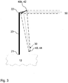
Fig. 3 shows a third example of an antenna system useful for understanding the invention, in which a feed arrangement is carried out as a secondary antenna acting as focusing element. -
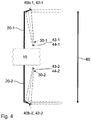
Fig. 4 shows a fourth example of an antenna system useful for understanding the invention, comprising two antenna arrangements being mounted at respective tips of two booms that are arranged on opposite sides of a platform of the antenna system. -
Fig. 5 shows an embodiment of an antenna system according to the invention, comprising two antenna arrangements being mounted at the tips of two booms and an additional third antenna being arranged on or close to the platform. -
Fig. 1 shows a first example of a known space borne antenna system. The antenna system comprises aplatform 10, aboom 20, afeed system 30 and a passiveradiating element 40a. Theplatform 10 may be, for example, a satellite or a spacecraft. Theboom 20 can be, for example, a mast or a telescopic arm. Theboom 20 comprises afirst end 21 and asecond end 22. While thefirst end 21 is attached to theplatform 10, thesecond end 22 which constitutes a tip of theboom 20 bears the radiatingelement 40a. This means, the radiatingelement 40a is mounted at the tip of the boom. - In the example of
Fig. 1 , the radiatingelement 40a is a flat reflector, such as a reflecting plane, or a reflect-array which typically have a surface which is within one plane. Thefeed system 30 is arranged on or close to theplatform 10. Thefeed system 30 may comprise one or more antenna elements. The combination offeed system 30 and radiatingelement 40a is called an antenna arrangement. An electronics or control unit of thefeed system 30 which is not shown in the figures can be mounted in close vicinity of theplatform 10 or directly into theplatform 10. - The
feed system 30 and theradiating element 40a are arranged such that the radiatingelement 40a can receive electromagnetic waves from thefeed system 30 and redirect them in a different direction (beam direction 50). As a result, the antenna arrangement constitutes a transmit (Tx) antenna. - Furthermore, the antenna arrangement could be realized such that electromagnetic waves received by the radiating
element 40a may be directed to the feed system to constitute a receive (Rx) antenna. Likewise, the antenna system may be adapted to both receive and transmit electromagnetic waves, such that the antenna system constitutes a receive and transmit antenna. -
Fig. 2 shows a second known example of a space borne antenna system which differs from the example ofFig. 1 only in that, that the passive radiating element is areflector 40b which may have a concave surface. The reflector may be a parabolic reflector or of any other shape. - In the third example useful for understanding the invention and illustrated in
Fig. 3 the feed arrangement is a secondary antenna 44 consisting of a reflector 43 and afeed system 30 directed to the reflector or reflect-array. Thefeed system 30 may comprise one or more antenna elements. The reflector 43 may be realized alternatively as reflect-array. In this antenna system, thereflector 40b (or alternatively flat reflector, e.g. reflecting plane or reflect-array) at the tip of theboom 20 constitutes a primary antenna and the antenna 44 a secondary antenna. For transmission, theprimary antenna 42 on the tip of the boom receives electromagnetic waves from the secondary antenna 44 and forwards them in the direction of intention (beam direction 50). For reception, theprimary antenna element 42 receives electromagnetic waves from thebeam direction 50 and directs them in the direction of the secondary antenna 44. - Providing a feed arrangement on or close to the
platform 10 and thefirst end 21 of the boom, respectively, and a radiating element at thesecond end 22 of theboom 20 ensures that no RF (radio frequency) signals need to be routed along the boom via cables or waveguides. This approach avoids laying RF waveguides along the fixed or deployable boom, and minimizes calibration efforts and electrical losses in these waveguides. - An antenna system according to a fourth example illustrated in
Fig. 4 comprises two antenna arrangements. The first antenna arrangement comprises a first boom 20-1, a firstpassive radiating element 40b-1 (constituting a first primary antenna 42-1) at the tip of the first boom 20-1 and a first feed arrangement (i.e. first secondary antenna 44-1) close to or arranged in theplatform 10. The second antenna arrangement comprises a second boom 20-2, a secondpassive radiating element 40b-2 (constituting a second primary antenna 42-2) at the tip of the second boom 20-2 and a second feed arrangement (i.e. a second secondary antenna 44-2) close to or arranged in theplatform 10. The first and second booms 20-1 and 20-2 are arranged on opposite sides of theplatform 10. A baseline (distance) between the tworadiators 40b-1 and 40b-2 is depicted with 60. Both feed arrangements (first secondary antenna 44-1 and second secondary antenna 44-2) consist of a reflecting element 43-1 and 43-2 as well as a feed system 30-1 and 30-2. - In this antenna system, one of the antenna arrangements may be used as transmit (Tx) antenna while the other antenna arrangement may be used as receive (Rx) antenna. Alternatively, at least one of the antenna arrangements might be adapted to be a receive and transmit antenna.
- The embodiment of an antenna system according to the invention (
Fig. 5 ) is based on the fourth example illustrated inFig. 4 . In addition, afurther antenna 70 is mounted on or in close vicinity to theplatform 10. Theantenna 70 comprises a reflector or reflect-array 72 and afeed system 71. While thefurther antenna 70 is adapted to receive electromagnetic waves (receive Rx antenna), the two other antenna arrangements are configured to transmit electromagnetic waves (transmit Tx antennas). Alternatively, receive and transmit direction might be interchanged between the antenna arrangements. - An antenna system as illustrated in
Figs. 4 and5 may be used as across track and/or along track interferometric SAR. -
- 10
- platform
- 20
- boom
- 20-1
- first boom
- 20-2
- second boom
- 21
- first end of boom
- 22
- second end of boom
- 30
- feed system
- 30-1
- first feed system
- 30-2
- second feed system
- 40
- radiating element
- 40a
- reflecting plane / reflect-array
- 40b
- reflector
- 40b-1
- first reflector
- 40b-2
- second reflector
- 42
- primary antenna
- 42-1
- first primary antenna
- 42-2
- second primary antenna
- 43
- reflector / reflecting plane / reflect-array
- 43-1
- first reflector / reflecting plane / reflect-array
- 43-2
- second reflector / reflecting plane / reflect-array
- 44
- secondary antenna
- 44-1
- first secondary antenna
- 44-2
- second secondary antenna
- 50
- beam direction
- 60
- geometric baseline
- 70
- antenna or antenna system
- 71
- feed system
- 72
- reflector / reflect-array
- Rx
- receive beam direction
- Tx
- transmit beam direction
Claims (6)
- A space borne antenna system, comprising- a platform (10) having a first boom (20-1) and a second boom (20-2), wherein the first boom (20-1) extends from a first side of the platform (10) in a first direction and the second boom (20-2) extends from a second side of the platform (10) in a second direction, wherein the first and second sides are opposite sides of the platform (10) and the first direction is opposite to the second direction;- a first antenna arrangement comprising following elements:- a first feed arrangement (30-1) arranged on or close to the platform (10), wherein the first feed arrangement (30-1) comprises a first secondary antenna (43-1), and- a first radiating element (40b-1) being mounted at a tip of the first boom, wherein the tip of the first boom is remote to the platform (10), wherein the first boom comprises a first end and a second end, wherein the first end of the first boom is attached to the platform (10) and the second end of the first boom is the tip of the first boom, wherein the first radiating element (40b-1) is adapted to receive electromagnetic waves from the first feed arrangement (30-1) and to redirect it in a different direction and/or vice versa, wherein said different direction is a main radiation direction of the first radiating element (40b-1);- a second antenna arrangement comprising following elements:- a second feed arrangement (30-2) arranged on or close to the platform (10), wherein the second feed arrangement (30-2) comprises a second secondary antenna (43-2), and- a second radiating element (40b-2) being mounted at a tip of the second boom, wherein the tip of the second boom is remote to the platform (10), wherein the second boom comprises a first end and a second end, wherein the first end of the second boom is attached to the platform (10) and the second end of the second boom is the tip of the second boom, wherein the second radiating element (40b-2) is adapted to receive electromagnetic waves from the second feed arrangement (30-2) and to redirect it in a different direction and/or vice versa, wherein said different direction is a main radiation direction of the second radiating element (40b-2); and- a further antenna (70) arranged on the platform (10) and adapted for reception and/or transmission of electromagnetic waves in a main radiation direction, wherein the first and second booms (20-1, 20-2) are deployable or extractable structures, and wherein a boom length of the first boom (20-1) is longer than a diameter of the first radiating element (40b-1), and wherein a boom length of the second boom (20-2) is longer than a diameter of the second radiating element (40b-2),wherein the main radiating directions of the first and second radiating elements correspond to the main radiating direction of the further antenna (70),
wherein, in a first alternative, the further antenna (70) is adapted to receive electromagnetic waves, while the first and second antenna arrangements are adapted to transmit electromagnetic waves, or
wherein, in a second alternative, the further antenna (70), the first and the second antenna arrangements are adapted such that the receive and transmit directions are interchanged with respect to the first alternative. - The antenna system according to claim 1, wherein each of the first and second radiating elements (40b-1, 40b-2) comprises a reflecting plane or a reflector or a reflect-array.
- The antenna system according to claim 1 or 2, wherein each of the first and second secondary antennas (44-1, 44-2) comprises a reflector antenna or a reflect-array antenna or antenna elements.
- The antenna system according to any one of the foregoing claims, wherein the first feed arrangement (30-1) is arranged on or close to the first side of the platform (10), and wherein the second feed arrangement (30-2) is arranged on or close to the second side of the platform (10).
- The antenna system according to any one of the foregoing claims, wherein the further antenna (70) is arranged on a third side of the platform (10) different from the first and second sides of the platform (10).
- The antenna system according to any one of the foregoing claims, wherein the space born antenna system is synthetic aperture radar.
Priority Applications (2)
| Application Number | Priority Date | Filing Date | Title |
|---|---|---|---|
| EP12007610.4A EP2731193B1 (en) | 2012-11-08 | 2012-11-08 | Space borne antenna system |
| CA2829633A CA2829633C (en) | 2012-11-08 | 2013-10-07 | Space borne antenna system |
Applications Claiming Priority (1)
| Application Number | Priority Date | Filing Date | Title |
|---|---|---|---|
| EP12007610.4A EP2731193B1 (en) | 2012-11-08 | 2012-11-08 | Space borne antenna system |
Publications (2)
| Publication Number | Publication Date |
|---|---|
| EP2731193A1 EP2731193A1 (en) | 2014-05-14 |
| EP2731193B1 true EP2731193B1 (en) | 2019-07-24 |
Family
ID=47257341
Family Applications (1)
| Application Number | Title | Priority Date | Filing Date |
|---|---|---|---|
| EP12007610.4A Active EP2731193B1 (en) | 2012-11-08 | 2012-11-08 | Space borne antenna system |
Country Status (2)
| Country | Link |
|---|---|
| EP (1) | EP2731193B1 (en) |
| CA (1) | CA2829633C (en) |
Families Citing this family (1)
| Publication number | Priority date | Publication date | Assignee | Title |
|---|---|---|---|---|
| CN105510916B (en) * | 2015-11-30 | 2017-10-17 | 中国科学院电子学研究所 | A kind of moving target detection method based on InISAR systems |
Family Cites Families (2)
| Publication number | Priority date | Publication date | Assignee | Title |
|---|---|---|---|---|
| US6323817B1 (en) * | 2000-01-19 | 2001-11-27 | Hughes Electronics Corporation | Antenna cluster configuration for wide-angle coverage |
| US6424314B1 (en) * | 2001-05-16 | 2002-07-23 | Space Systems/Loral, Inc. | Four axis boom for mounting reflector on satellite |
-
2012
- 2012-11-08 EP EP12007610.4A patent/EP2731193B1/en active Active
-
2013
- 2013-10-07 CA CA2829633A patent/CA2829633C/en active Active
Non-Patent Citations (1)
| Title |
|---|
| D. M. SIMPSON: "The "Snapdragon" Family", PROCEEDINGS OF THE EUROPEAN CONFERENCE ON SPACECRAFT STRUCTURES, MATERIALS AND MECHANICAL TESTING, 1 January 2001 (2001-01-01), pages 337 - 344, XP055376639 * |
Also Published As
| Publication number | Publication date |
|---|---|
| CA2829633C (en) | 2021-08-24 |
| EP2731193A1 (en) | 2014-05-14 |
| CA2829633A1 (en) | 2014-05-08 |
Similar Documents
| Publication | Publication Date | Title |
|---|---|---|
| CN108011190B (en) | Multi-frequency-band integrated wide-area detection receiving antenna | |
| JP6501361B2 (en) | High frequency power supply method to unfolding structure | |
| KR101656204B1 (en) | Source for parabolic antenna | |
| US9136607B2 (en) | Antenna beam steering through waveguide mode mixing | |
| KR101887589B1 (en) | Long Range Radar Antenna having Improved Detection Performance and Connection Module Improving Electrical Characteristics therein | |
| EP2260537A1 (en) | Antenna feed assembly | |
| USH1383H (en) | Space-based tethered phased-array antenna | |
| US7242360B2 (en) | High power dual band high gain antenna system and method of making the same | |
| CN109167186A (en) | A kind of Shared aperture two-band phased array antenna system based on 5G communication | |
| KR101913819B1 (en) | Long Range Radar Array Antenna, Horizontal Array with Antenna Radiating Elements, Antenna Apparatus for Long Range Radar | |
| EP2731193A1 (en) | Space borne antenna system | |
| US9979077B2 (en) | Vehicle antenna for satellite communication | |
| US8315557B1 (en) | Common aperture antenna for multiple contoured beams and multiple spot beams | |
| EP4404385B1 (en) | ANTENNA DEVICE | |
| WO2019121094A1 (en) | Integrated antenna arrangement | |
| KR102394992B1 (en) | Antenna apparatus and identification of friend or foe system with the same | |
| KR102394771B1 (en) | Antenna apparatus and identification of friend or foe system with the same | |
| US20220252711A1 (en) | Long-range object detection system | |
| US8664807B2 (en) | Planar tri-mode cavity | |
| KR100822705B1 (en) | Phase Detection Direction Detection Antenna | |
| US12166276B1 (en) | Deployable omnidirectional antenna for ground communication | |
| CN101636874A (en) | Structure for influencing the emission characteristics of a reflector antenna, in particular a centrally focused reflector antenna | |
| US9575171B1 (en) | Single antenna altimeter | |
| Fügen et al. | Periscope antenna for a spaceborne single-pass interferometric SAR instrument | |
| RU2542890C2 (en) | Dipole antenna |
Legal Events
| Date | Code | Title | Description |
|---|---|---|---|
| PUAI | Public reference made under article 153(3) epc to a published international application that has entered the european phase |
Free format text: ORIGINAL CODE: 0009012 |
|
| 17P | Request for examination filed |
Effective date: 20121108 |
|
| AK | Designated contracting states |
Kind code of ref document: A1 Designated state(s): AL AT BE BG CH CY CZ DE DK EE ES FI FR GB GR HR HU IE IS IT LI LT LU LV MC MK MT NL NO PL PT RO RS SE SI SK SM TR |
|
| AX | Request for extension of the european patent |
Extension state: BA ME |
|
| R17P | Request for examination filed (corrected) |
Effective date: 20141114 |
|
| RAP1 | Party data changed (applicant data changed or rights of an application transferred) |
Owner name: AIRBUS DS GMBH |
|
| STAA | Information on the status of an ep patent application or granted ep patent |
Free format text: STATUS: EXAMINATION IS IN PROGRESS |
|
| 17Q | First examination report despatched |
Effective date: 20170606 |
|
| RAP1 | Party data changed (applicant data changed or rights of an application transferred) |
Owner name: AIRBUS DEFENCE AND SPACE GMBH |
|
| GRAP | Despatch of communication of intention to grant a patent |
Free format text: ORIGINAL CODE: EPIDOSNIGR1 |
|
| STAA | Information on the status of an ep patent application or granted ep patent |
Free format text: STATUS: GRANT OF PATENT IS INTENDED |
|
| INTG | Intention to grant announced |
Effective date: 20190220 |
|
| GRAS | Grant fee paid |
Free format text: ORIGINAL CODE: EPIDOSNIGR3 |
|
| GRAA | (expected) grant |
Free format text: ORIGINAL CODE: 0009210 |
|
| STAA | Information on the status of an ep patent application or granted ep patent |
Free format text: STATUS: THE PATENT HAS BEEN GRANTED |
|
| AK | Designated contracting states |
Kind code of ref document: B1 Designated state(s): AL AT BE BG CH CY CZ DE DK EE ES FI FR GB GR HR HU IE IS IT LI LT LU LV MC MK MT NL NO PL PT RO RS SE SI SK SM TR |
|
| REG | Reference to a national code |
Ref country code: GB Ref legal event code: FG4D |
|
| REG | Reference to a national code |
Ref country code: CH Ref legal event code: EP |
|
| REG | Reference to a national code |
Ref country code: DE Ref legal event code: R096 Ref document number: 602012062182 Country of ref document: DE |
|
| REG | Reference to a national code |
Ref country code: AT Ref legal event code: REF Ref document number: 1159304 Country of ref document: AT Kind code of ref document: T Effective date: 20190815 |
|
| REG | Reference to a national code |
Ref country code: IE Ref legal event code: FG4D |
|
| REG | Reference to a national code |
Ref country code: NL Ref legal event code: MP Effective date: 20190724 |
|
| REG | Reference to a national code |
Ref country code: LT Ref legal event code: MG4D |
|
| REG | Reference to a national code |
Ref country code: AT Ref legal event code: MK05 Ref document number: 1159304 Country of ref document: AT Kind code of ref document: T Effective date: 20190724 |
|
| PG25 | Lapsed in a contracting state [announced via postgrant information from national office to epo] |
Ref country code: FI Free format text: LAPSE BECAUSE OF FAILURE TO SUBMIT A TRANSLATION OF THE DESCRIPTION OR TO PAY THE FEE WITHIN THE PRESCRIBED TIME-LIMIT Effective date: 20190724 Ref country code: NO Free format text: LAPSE BECAUSE OF FAILURE TO SUBMIT A TRANSLATION OF THE DESCRIPTION OR TO PAY THE FEE WITHIN THE PRESCRIBED TIME-LIMIT Effective date: 20191024 Ref country code: BG Free format text: LAPSE BECAUSE OF FAILURE TO SUBMIT A TRANSLATION OF THE DESCRIPTION OR TO PAY THE FEE WITHIN THE PRESCRIBED TIME-LIMIT Effective date: 20191024 Ref country code: SE Free format text: LAPSE BECAUSE OF FAILURE TO SUBMIT A TRANSLATION OF THE DESCRIPTION OR TO PAY THE FEE WITHIN THE PRESCRIBED TIME-LIMIT Effective date: 20190724 Ref country code: AT Free format text: LAPSE BECAUSE OF FAILURE TO SUBMIT A TRANSLATION OF THE DESCRIPTION OR TO PAY THE FEE WITHIN THE PRESCRIBED TIME-LIMIT Effective date: 20190724 Ref country code: HR Free format text: LAPSE BECAUSE OF FAILURE TO SUBMIT A TRANSLATION OF THE DESCRIPTION OR TO PAY THE FEE WITHIN THE PRESCRIBED TIME-LIMIT Effective date: 20190724 Ref country code: LT Free format text: LAPSE BECAUSE OF FAILURE TO SUBMIT A TRANSLATION OF THE DESCRIPTION OR TO PAY THE FEE WITHIN THE PRESCRIBED TIME-LIMIT Effective date: 20190724 Ref country code: NL Free format text: LAPSE BECAUSE OF FAILURE TO SUBMIT A TRANSLATION OF THE DESCRIPTION OR TO PAY THE FEE WITHIN THE PRESCRIBED TIME-LIMIT Effective date: 20190724 Ref country code: PT Free format text: LAPSE BECAUSE OF FAILURE TO SUBMIT A TRANSLATION OF THE DESCRIPTION OR TO PAY THE FEE WITHIN THE PRESCRIBED TIME-LIMIT Effective date: 20191125 |
|
| PG25 | Lapsed in a contracting state [announced via postgrant information from national office to epo] |
Ref country code: AL Free format text: LAPSE BECAUSE OF FAILURE TO SUBMIT A TRANSLATION OF THE DESCRIPTION OR TO PAY THE FEE WITHIN THE PRESCRIBED TIME-LIMIT Effective date: 20190724 Ref country code: LV Free format text: LAPSE BECAUSE OF FAILURE TO SUBMIT A TRANSLATION OF THE DESCRIPTION OR TO PAY THE FEE WITHIN THE PRESCRIBED TIME-LIMIT Effective date: 20190724 Ref country code: ES Free format text: LAPSE BECAUSE OF FAILURE TO SUBMIT A TRANSLATION OF THE DESCRIPTION OR TO PAY THE FEE WITHIN THE PRESCRIBED TIME-LIMIT Effective date: 20190724 Ref country code: GR Free format text: LAPSE BECAUSE OF FAILURE TO SUBMIT A TRANSLATION OF THE DESCRIPTION OR TO PAY THE FEE WITHIN THE PRESCRIBED TIME-LIMIT Effective date: 20191025 Ref country code: RS Free format text: LAPSE BECAUSE OF FAILURE TO SUBMIT A TRANSLATION OF THE DESCRIPTION OR TO PAY THE FEE WITHIN THE PRESCRIBED TIME-LIMIT Effective date: 20190724 Ref country code: IS Free format text: LAPSE BECAUSE OF FAILURE TO SUBMIT A TRANSLATION OF THE DESCRIPTION OR TO PAY THE FEE WITHIN THE PRESCRIBED TIME-LIMIT Effective date: 20191124 |
|
| PG25 | Lapsed in a contracting state [announced via postgrant information from national office to epo] |
Ref country code: TR Free format text: LAPSE BECAUSE OF FAILURE TO SUBMIT A TRANSLATION OF THE DESCRIPTION OR TO PAY THE FEE WITHIN THE PRESCRIBED TIME-LIMIT Effective date: 20190724 |
|
| PG25 | Lapsed in a contracting state [announced via postgrant information from national office to epo] |
Ref country code: RO Free format text: LAPSE BECAUSE OF FAILURE TO SUBMIT A TRANSLATION OF THE DESCRIPTION OR TO PAY THE FEE WITHIN THE PRESCRIBED TIME-LIMIT Effective date: 20190724 Ref country code: PL Free format text: LAPSE BECAUSE OF FAILURE TO SUBMIT A TRANSLATION OF THE DESCRIPTION OR TO PAY THE FEE WITHIN THE PRESCRIBED TIME-LIMIT Effective date: 20190724 Ref country code: DK Free format text: LAPSE BECAUSE OF FAILURE TO SUBMIT A TRANSLATION OF THE DESCRIPTION OR TO PAY THE FEE WITHIN THE PRESCRIBED TIME-LIMIT Effective date: 20190724 Ref country code: EE Free format text: LAPSE BECAUSE OF FAILURE TO SUBMIT A TRANSLATION OF THE DESCRIPTION OR TO PAY THE FEE WITHIN THE PRESCRIBED TIME-LIMIT Effective date: 20190724 |
|
| PG25 | Lapsed in a contracting state [announced via postgrant information from national office to epo] |
Ref country code: SK Free format text: LAPSE BECAUSE OF FAILURE TO SUBMIT A TRANSLATION OF THE DESCRIPTION OR TO PAY THE FEE WITHIN THE PRESCRIBED TIME-LIMIT Effective date: 20190724 Ref country code: SM Free format text: LAPSE BECAUSE OF FAILURE TO SUBMIT A TRANSLATION OF THE DESCRIPTION OR TO PAY THE FEE WITHIN THE PRESCRIBED TIME-LIMIT Effective date: 20190724 Ref country code: CZ Free format text: LAPSE BECAUSE OF FAILURE TO SUBMIT A TRANSLATION OF THE DESCRIPTION OR TO PAY THE FEE WITHIN THE PRESCRIBED TIME-LIMIT Effective date: 20190724 Ref country code: IS Free format text: LAPSE BECAUSE OF FAILURE TO SUBMIT A TRANSLATION OF THE DESCRIPTION OR TO PAY THE FEE WITHIN THE PRESCRIBED TIME-LIMIT Effective date: 20200224 |
|
| REG | Reference to a national code |
Ref country code: DE Ref legal event code: R097 Ref document number: 602012062182 Country of ref document: DE |
|
| REG | Reference to a national code |
Ref country code: CH Ref legal event code: PL |
|
| PLBE | No opposition filed within time limit |
Free format text: ORIGINAL CODE: 0009261 |
|
| STAA | Information on the status of an ep patent application or granted ep patent |
Free format text: STATUS: NO OPPOSITION FILED WITHIN TIME LIMIT |
|
| PG2D | Information on lapse in contracting state deleted |
Ref country code: IS |
|
| PG25 | Lapsed in a contracting state [announced via postgrant information from national office to epo] |
Ref country code: MC Free format text: LAPSE BECAUSE OF FAILURE TO SUBMIT A TRANSLATION OF THE DESCRIPTION OR TO PAY THE FEE WITHIN THE PRESCRIBED TIME-LIMIT Effective date: 20190724 Ref country code: LI Free format text: LAPSE BECAUSE OF NON-PAYMENT OF DUE FEES Effective date: 20191130 Ref country code: CH Free format text: LAPSE BECAUSE OF NON-PAYMENT OF DUE FEES Effective date: 20191130 Ref country code: LU Free format text: LAPSE BECAUSE OF NON-PAYMENT OF DUE FEES Effective date: 20191108 |
|
| 26N | No opposition filed |
Effective date: 20200603 |
|
| REG | Reference to a national code |
Ref country code: BE Ref legal event code: MM Effective date: 20191130 |
|
| PG25 | Lapsed in a contracting state [announced via postgrant information from national office to epo] |
Ref country code: SI Free format text: LAPSE BECAUSE OF FAILURE TO SUBMIT A TRANSLATION OF THE DESCRIPTION OR TO PAY THE FEE WITHIN THE PRESCRIBED TIME-LIMIT Effective date: 20190724 |
|
| PG25 | Lapsed in a contracting state [announced via postgrant information from national office to epo] |
Ref country code: IE Free format text: LAPSE BECAUSE OF NON-PAYMENT OF DUE FEES Effective date: 20191108 |
|
| PG25 | Lapsed in a contracting state [announced via postgrant information from national office to epo] |
Ref country code: BE Free format text: LAPSE BECAUSE OF NON-PAYMENT OF DUE FEES Effective date: 20191130 |
|
| PG25 | Lapsed in a contracting state [announced via postgrant information from national office to epo] |
Ref country code: CY Free format text: LAPSE BECAUSE OF FAILURE TO SUBMIT A TRANSLATION OF THE DESCRIPTION OR TO PAY THE FEE WITHIN THE PRESCRIBED TIME-LIMIT Effective date: 20190724 |
|
| PG25 | Lapsed in a contracting state [announced via postgrant information from national office to epo] |
Ref country code: MT Free format text: LAPSE BECAUSE OF FAILURE TO SUBMIT A TRANSLATION OF THE DESCRIPTION OR TO PAY THE FEE WITHIN THE PRESCRIBED TIME-LIMIT Effective date: 20190724 Ref country code: HU Free format text: LAPSE BECAUSE OF FAILURE TO SUBMIT A TRANSLATION OF THE DESCRIPTION OR TO PAY THE FEE WITHIN THE PRESCRIBED TIME-LIMIT; INVALID AB INITIO Effective date: 20121108 |
|
| PG25 | Lapsed in a contracting state [announced via postgrant information from national office to epo] |
Ref country code: MK Free format text: LAPSE BECAUSE OF FAILURE TO SUBMIT A TRANSLATION OF THE DESCRIPTION OR TO PAY THE FEE WITHIN THE PRESCRIBED TIME-LIMIT Effective date: 20190724 |
|
| PGFP | Annual fee paid to national office [announced via postgrant information from national office to epo] |
Ref country code: DE Payment date: 20251119 Year of fee payment: 14 |
|
| PGFP | Annual fee paid to national office [announced via postgrant information from national office to epo] |
Ref country code: GB Payment date: 20251121 Year of fee payment: 14 |
|
| PGFP | Annual fee paid to national office [announced via postgrant information from national office to epo] |
Ref country code: IT Payment date: 20251125 Year of fee payment: 14 |
|
| PGFP | Annual fee paid to national office [announced via postgrant information from national office to epo] |
Ref country code: FR Payment date: 20251125 Year of fee payment: 14 |