EP2731173A1 - Bus bar cover, and bus bar with cover - Google Patents
Bus bar cover, and bus bar with cover Download PDFInfo
- Publication number
- EP2731173A1 EP2731173A1 EP12821846.8A EP12821846A EP2731173A1 EP 2731173 A1 EP2731173 A1 EP 2731173A1 EP 12821846 A EP12821846 A EP 12821846A EP 2731173 A1 EP2731173 A1 EP 2731173A1
- Authority
- EP
- European Patent Office
- Prior art keywords
- bus bar
- portions
- cover
- main body
- electrode terminals
- Prior art date
- Legal status (The legal status is an assumption and is not a legal conclusion. Google has not performed a legal analysis and makes no representation as to the accuracy of the status listed.)
- Granted
Links
Images






Classifications
-
- H—ELECTRICITY
- H01—ELECTRIC ELEMENTS
- H01B—CABLES; CONDUCTORS; INSULATORS; SELECTION OF MATERIALS FOR THEIR CONDUCTIVE, INSULATING OR DIELECTRIC PROPERTIES
- H01B7/00—Insulated conductors or cables characterised by their form
- H01B7/02—Disposition of insulation
-
- H—ELECTRICITY
- H01—ELECTRIC ELEMENTS
- H01B—CABLES; CONDUCTORS; INSULATORS; SELECTION OF MATERIALS FOR THEIR CONDUCTIVE, INSULATING OR DIELECTRIC PROPERTIES
- H01B17/00—Insulators or insulating bodies characterised by their form
- H01B17/56—Insulating bodies
-
- H—ELECTRICITY
- H01—ELECTRIC ELEMENTS
- H01M—PROCESSES OR MEANS, e.g. BATTERIES, FOR THE DIRECT CONVERSION OF CHEMICAL ENERGY INTO ELECTRICAL ENERGY
- H01M50/00—Constructional details or processes of manufacture of the non-active parts of electrochemical cells other than fuel cells, e.g. hybrid cells
- H01M50/50—Current conducting connections for cells or batteries
- H01M50/502—Interconnectors for connecting terminals of adjacent batteries; Interconnectors for connecting cells outside a battery casing
- H01M50/505—Interconnectors for connecting terminals of adjacent batteries; Interconnectors for connecting cells outside a battery casing comprising a single busbar
-
- H—ELECTRICITY
- H01—ELECTRIC ELEMENTS
- H01M—PROCESSES OR MEANS, e.g. BATTERIES, FOR THE DIRECT CONVERSION OF CHEMICAL ENERGY INTO ELECTRICAL ENERGY
- H01M50/00—Constructional details or processes of manufacture of the non-active parts of electrochemical cells other than fuel cells, e.g. hybrid cells
- H01M50/50—Current conducting connections for cells or batteries
- H01M50/502—Interconnectors for connecting terminals of adjacent batteries; Interconnectors for connecting cells outside a battery casing
- H01M50/509—Interconnectors for connecting terminals of adjacent batteries; Interconnectors for connecting cells outside a battery casing characterised by the type of connection, e.g. mixed connections
- H01M50/51—Connection only in series
-
- H—ELECTRICITY
- H01—ELECTRIC ELEMENTS
- H01M—PROCESSES OR MEANS, e.g. BATTERIES, FOR THE DIRECT CONVERSION OF CHEMICAL ENERGY INTO ELECTRICAL ENERGY
- H01M50/00—Constructional details or processes of manufacture of the non-active parts of electrochemical cells other than fuel cells, e.g. hybrid cells
- H01M50/50—Current conducting connections for cells or batteries
- H01M50/502—Interconnectors for connecting terminals of adjacent batteries; Interconnectors for connecting cells outside a battery casing
- H01M50/521—Interconnectors for connecting terminals of adjacent batteries; Interconnectors for connecting cells outside a battery casing characterised by the material
- H01M50/522—Inorganic material
-
- H—ELECTRICITY
- H01—ELECTRIC ELEMENTS
- H01M—PROCESSES OR MEANS, e.g. BATTERIES, FOR THE DIRECT CONVERSION OF CHEMICAL ENERGY INTO ELECTRICAL ENERGY
- H01M50/00—Constructional details or processes of manufacture of the non-active parts of electrochemical cells other than fuel cells, e.g. hybrid cells
- H01M50/50—Current conducting connections for cells or batteries
- H01M50/571—Methods or arrangements for affording protection against corrosion; Selection of materials therefor
-
- Y—GENERAL TAGGING OF NEW TECHNOLOGICAL DEVELOPMENTS; GENERAL TAGGING OF CROSS-SECTIONAL TECHNOLOGIES SPANNING OVER SEVERAL SECTIONS OF THE IPC; TECHNICAL SUBJECTS COVERED BY FORMER USPC CROSS-REFERENCE ART COLLECTIONS [XRACs] AND DIGESTS
- Y02—TECHNOLOGIES OR APPLICATIONS FOR MITIGATION OR ADAPTATION AGAINST CLIMATE CHANGE
- Y02E—REDUCTION OF GREENHOUSE GAS [GHG] EMISSIONS, RELATED TO ENERGY GENERATION, TRANSMISSION OR DISTRIBUTION
- Y02E60/00—Enabling technologies; Technologies with a potential or indirect contribution to GHG emissions mitigation
- Y02E60/10—Energy storage using batteries
Definitions
- the present invention relates to a bus bar cover, and a bus bar with cover.
- Battery modules for automobiles such as electric automobiles or hybrid automobiles include a cell group in which a plurality of cells are arranged in a row.
- Each of the cells forming the cell group has a positive electrode terminal and a negative electrode terminal, and the electrode terminals having opposite polarities respectively included in adjacent cells are electrically connected by a metal bus bar.
- the bus bar is attached to each pair of such electrode terminals at a plurality of locations on the cell group. Such a bus bar is used to electrically connect the cells forming the cell group in series.
- a battery wiring module is used that can simultaneously position a plurality of bus bars on the respective pairs of electrode terminals as shown in Patent Document 1 and so on.
- This sort of battery wiring module is configured such that a plurality of bus bars are held by an insulating substrate made of a resin or the like, and is placed on and fixed to the cell group.
- the above-described battery wiring module is used in this state, it may be rather difficult to attach the bus bars to the respective pairs of electrode terminals. Accordingly, in the above-described battery module, all cells may not be treated as one cell group, but they may be used in a state of being divided into a plurality of cell groups. Furthermore, the cells may be divided into a plurality of cell groups also due to limitations of space in which the battery module is to be installed, for example.
- the plurality of cell groups are electrically connected to each other by dedicated bus bars. Both ends of this sort of bus bar are fixed by bolting or the like respectively to electrode terminals having opposite polarities.
- the bus bar extends to link the cell groups in a state where both ends are fixed.
- Patent Document 1 JP 2011-8957A
- bus bar extending to link the cell groups is left exposed, tools or the like may be brought into contact with the bus bar, which may result in a short-circuit of the battery module. Accordingly, it is conceivable to cover the bus bar with an insulating material. However, the ends of the bus bar have to be exposed, at least during the attachment operation of the bus bar, in order to avoid interference with the attachment operation. Preferably, the ends of the bus bar are also covered by an insulating material after the bus bar is attached between the cell groups.
- the present invention was made in view of these circumstances, and it is an object thereof to provide a technique for covering, with an insulating material, a bus bar for electrically connecting cell groups, wherein ends of the bus bar can be exposed from the insulating material during attachment of the bus bar between the cell groups, and the ends of the bus bar can be covered by the insulating material after attachment of the bus bar between the cell groups.
- the present invention is directed to an insulating bus bar cover that is attachable to a bus bar between a cell group in which a plurality of cells including a pair of positive and negative electrode terminals are arranged in a row and a cell group of the same type adjacent to said cell group, both ends of the bus bar being respectively fixable to electrode terminals having opposite polarities in order to electrically connect the electrode terminals,
- the bus bar cover including: a main body portion for covering the bus bar while exposing both ends of the bus bar; hinge portions that are provided at ends of the main body portion; and lid portions that are attached via the hinge portions to the main body portion, and are pivotable by the hinge portions so as to cover or expose the ends of the bus bar. Since the bus bar cover has this configuration, the ends of the bus bar can be exposed from or covered by the bus bar cover as necessary.
- the bus bar cover preferably further includes engagement portions that are provided at the lid portions; and engageable portions that are provided at the ends of the main body portion, wherein engagement of the engageable portions with the engagement portions fixes the lid portions in a state where the lid portions cover the ends of the bus bar. Since the bus bar cover includes the engagement portions and the engageable portions, the lid portions are fixed in a state where they cover the ends of the bus bar.
- the bus bar cover is preferably configured such that the main body portion includes: a tubular member for covering the bus bar while exposing both ends of the bus bar; and frame members that are provided at ends of the tubular member, and surround the ends of the bus bar exposed from the tubular member; and the hinge portions and the engageable portions are provided on the frame members.
- the bus bar cover may be configured such that the tubular member includes a bottom portion that covers a lower face of the bus bar and a top portion that covers an upper face of the bus bar, and the bottom portion and the top portion are detachably attached to the bus bar. Since the tubular member is detachably attached to the bus bar, the bus bar cover can be attached later to the bus bar.
- the bus bar cover may be configured such that the ends of the bus bar respectively include a fixing portion that can be placed on the electrode terminals and fixed to the electrode terminals, and a rising portion that rises from the fixing portion. Since the ends of the bus bar include the fixing portions and the rising portions, positioning with respect to the electrode terminals that are to be fixed to the fixing portions can be easily performed.
- the present invention is directed to a bus bar with a cover, including: a bus bar that is fixable between a cell group in which a plurality of cells including a pair of positive and negative electrode terminals are arranged in a row and a cell group of the same type adjacent to said cell group, both ends of the bus bar being respectively fixable to electrode terminals having opposite polarities in order to electrically connect the electrode terminals; and an insulating bus bar cover that is attachable to the bus bar, and includes: a main body portion for covering the bus bar while exposing both ends of the bus bar, hinge portions that are provided at ends of the main body portion, and lid portions that are attached via the hinge portions to the main body portion, and are pivotable by the hinge portions so as to cover or expose the ends of the bus bar.
- the present invention can provide a technique for covering, with an insulating material, a bus bar for electrically connecting cell groups, wherein ends of the bus bar can be exposed from the insulating material during attachment of the bus bar between the cell groups, and the ends of the bus bar can be covered by the insulating material after attachment of the bus bar between the cell groups.
- FIG. 1 is a plan view of a battery module 1 including a bus bar 2 with cover according to Embodiment 1.
- the battery module 1 shown in FIG. 1 is used as a drive source for automobiles such as electric automobiles and hybrid automobiles.
- the battery module 1 is configured by a first battery module 1A and a second battery module 1B that are connected to each other via the bus bar 2 with cover.
- the first battery module 1A is shown on the left side
- the second battery module 1B is shown on the right side.
- FIG. 1 corresponds to the front side (the front face side) of the battery module 1
- the upper side in FIG. 1 corresponds to the rear side (the rear face side) of the battery module 1.
- the left-right direction in FIG. 1 corresponds to the left-right direction of the battery module 1.
- the first battery module 1A includes two cell groups 3, a first battery wiring module 4A fixed to the cell groups 3, and a cover 43A for the first battery wiring module 4A, which is placed on the first battery wiring module 4A.
- FIG. 2 is a plan view of the cell groups 3.
- FIG. 2 shows four cell groups 3A, 3B, 3C, and 3D that are arranged side by side. Of these, the cell groups 3A and 3B are used for the first battery module 1A, and the cell groups 3C and 3D are used for the second battery module 1B (described later).
- each of the cell groups 3 is configured by four cells 31 that are stacked in a row.
- the cell groups 3 (3A, 3B, 3C, and 3D) are arranged side by side with a gap interposed therebetween along the left-right direction shown in FIG. 2 .
- the gap between the cell group 3B used for the first battery module 1A and the cell group 3C used for the second battery module 1B is set to be larger than the gap between the other cell groups 3.
- Each cell 31 forming the cell groups 3 internally includes an electricity generating element (not shown).
- the cell 31 includes a main body portion 31a in the shape of a flat rectangular solid internally including the electricity generating element, and two electrode terminals 32 (32A and 32B) that are provided on an upper face of the main body portion 31a.
- One of the electrode terminals, denoted by 32A, is a positive electrode
- the other electrode terminal, denoted by 32B is a negative electrode.
- the electrode terminals 32A and 32B of the cell groups 3 (3A, 3B, 3C, and 3D) vertically project upward from the upper faces of the cells 31 (the main body portions 31a).
- Each of the electrode terminals 32 (32A and 32B) is configured by a nut in the shape of a square tube, and a round screw hole 33 is formed through the center of the nut.
- the cells 31 forming the cell groups 3 are arranged such that their electrode terminals 32 (32A and 32B) face in the same direction (upward).
- the cells 31 in the cell groups 3 are arranged such that the adjacent electrode terminals 32 of the adjacent cells 31 have opposite polarities. That is to say, the positive and negative electrode terminals 32 are alternately arranged in the direction in which the cells 31 are stacked in a row (the front-rear direction of the cell groups 3).
- the cell groups 3A and 3B used for the first battery module 1A are arranged such that the adjacent electrode terminals 32 of the adjacent cells 31 respectively in the different cell groups 3A and 3B have opposite polarities.
- the cell group 3B used for the first battery module 1A and the cell group 3C used for the second battery module 1B are arranged such that the adjacent electrode terminals 32 of the adjacent cells 31 respectively in the different cell groups 3B and 3C have opposite polarities.
- the electrode terminals 32 (32A and 32B) of the cell groups 3A and 3B used for the first battery module 1A are arranged on the same plane.
- the cell groups 3 (3A, 3B, 3C, and 3D) are placed on and fixed to a holding plate (not shown) that is disposed on the lower faces of the cells 31.
- FIG. 3 is a plan view of the first battery wiring module 4A.
- the first battery wiring module 4A is placed on the upper faces of the cell groups 3A and 3B and attached to the cell groups 3A and 3B.
- the two cell groups 3A and 3B are connected by the first battery wiring module 4A.
- This first battery wiring module 4A mainly includes a plurality of connection members 41, and a resin protector 42A in the shape of a container that accommodates the connection members 41.
- connection members 41 are formed by processing a metal material such as copper, copper alloy, stainless steel (SUS), or aluminum, into a predetermined shape.
- the connection members 41 each have a substantially elongated (belt-like) shape, and are configured as members generally known as bus bars.
- two types of connection members having different lengths are used as the connection members 41. Of these, the longer ones are referred to as first connection members 41A, and the shorter ones are referred to as second connection members 41B.
- FIG. 4 is a plan view of the first connection member 41A. As shown in FIG.
- the first connection member 41A includes an elongated main body portion 141 (141A), through holes 48 through which shank portions of fixing bolts are inserted respectively at both ends in the longitudinal direction of the main body portion 141 (141A), and cut-out portions 49 that sandwich the through hole 48 at each end of the main body portion 141 (141A).
- FIG. 5 is a plan view of the second connection member 41B.
- the second connection member 41B has the same basic configuration as that of the first connection member 41A although the length is shorter than that of the first connection member 41A.
- the second connection member 41B includes an elongated main body portion 141 (141B), through holes 48 through which shank portions of fixing bolts are inserted respectively at both ends in the longitudinal direction of the main body portion 141 (141B), and cut-out portions 49 that sandwich the through hole 48 at each end of the main body portion 141 (141B).
- connection members 41 extend to link the electrode terminals 32A and 32B having opposite polarities so as to electrically connect these electrode terminals, at a plurality of locations on the cell groups 3.
- the cells 31 forming the cell groups 3 (3A and 3B) are connected in series by the connection members 41.
- the first connection member 41A is used to electrically connect the electrode terminals 32A and 32B having opposite polarities of the adjacent cells 31 respectively in the cell groups 3A and 3B.
- the second connection member 41B is used to electrically connect the electrode terminals 32A and 32B having opposite polarities of the cells 31 that are adjacent to each other in the direction in which they are stacked in a row (the front-rear direction), in each of the cell groups 3A and 3B.
- the connection members 41 are used in a state where they are held by the resin protector 42A (see FIG. 3 ).
- connection members 41 are placed on the electrode terminals 32 and are fixed to the electrode terminals 32. At that time, the position of the through hole 48 at each end of each connection member 41 is set to the position of the screw hole 33 of the corresponding electrode terminal 32. Then, a shank portion of a fixing bolt (not shown) is inserted into the through hole 48 of the connection member 41 and the screw hole 33 of the electrode terminal 32, and the fixing bolt is screwed into the screw hole 33 such that the connection member 41 and the electrode terminal 32 are in close contact with each other.
- a fixing bolt (not shown) is inserted into the through hole 48 of the connection member 41 and the screw hole 33 of the electrode terminal 32, and the fixing bolt is screwed into the screw hole 33 such that the connection member 41 and the electrode terminal 32 are in close contact with each other.
- the through hole 48 provided in the connection member 41 is in the shape of a so-called elongated hole when viewed from above, and is set to be larger than the screw hole 33 of the electrode terminal 32. Furthermore, the through hole 48 is elongated in the longitudinal direction of the connection member 41. Since the connection member 41 includes such an elongated through hole 48, the through hole 48 of the connection member 41 can be positioned on the screw hole 33 of the electrode terminal 32 such that the fixing bolt can be inserted into these holes even if the position of the electrode terminal 32 is dislocated from the position where it should be. Note that such a dislocation of the electrode terminals 32 is caused by, for example, attachment errors of the electrode terminals 32 on the cells 31, deformation such as swelling of the cells 31, or errors in the arrangement pitches in the cell groups 3A and 3B.
- the plurality of connection members 41 form a predetermined pattern in the container-like resin protector 42A (see FIG. 3 ).
- the first connection members 41A are arranged along the left-right direction in FIG. 3 .
- the second connection members 41B are arranged along the vertical direction in FIG. 3 . That is to say, the first connection members 41A and the second connection members 41B are arranged along directions that are perpendicular to each other.
- the resin protector 42A is formed by processing an insulating composite resin material into a predetermined shape.
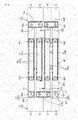
- FIG. 6 is a plan view of coupling units 42A1, 42A2, 42A3, and 42A4 forming the resin protector 42A.
- the resin protector 42A of this embodiment is formed by combining the four coupling units 42A1, 42A2, 42A3, and 42A4 shown in FIG. 6 .
- connection member accommodating portions 43 (43A) that accommodate the first connection members 41A.
- the connection member accommodating portions 43 (43A) are each in the shape of a small container that extends along the left-right direction in FIG. 6 , inside of which the first connection member 41A is held. Furthermore, the connection member accommodating portions 43 (43A) can be extended and retracted along the longitudinal direction of the first connection members 41A.
- connection member accommodating portion 43 (43A) includes an elongated bottom plate portion on which the first connection member 41A is placed, and a peripheral wall portion in the shape of a square tube that surrounds the bottom plate portion. Each of the bottom plate portion and the peripheral wall portion is divided between the coupling unit 42A1 side and the coupling unit 43A2 side. Both ends in the longitudinal direction of the bottom plate portion are respectively provided with opening portions 44. At the opening portions 44, the ends of the first connection member 41A are exposed from the connection member accommodating portion 43 (43A) so as to allow contact with the electrode terminals 32.
- the inner face of the peripheral wall portion is provided with a plurality of restricting protrusions 46 that restrict upward movement of the first connection member 41A in the thickness direction (in the upper direction).
- the restricting protrusions 46 are shaped so as to project from the inner face of the peripheral wall portion, and press the first connection member 41A from its upper face side to the bottom plate portion side.
- the inner face of the peripheral wall portion is further provided with a plurality of engagement protrusions 47 that respectively engage with the cut-out portions 49 of the first connection member 41A.
- the engagement protrusions 47 are shaped so as to project from the inner face of the peripheral wall portion, and extend along the longitudinal direction of the first connection member 41A.
- the engagement protrusions 47 are each set to be smaller than the cut-out portion 49, and a gap is provided in advance between both ends in the longitudinal direction of the engagement protrusion 47 and the cut-out portion 49.
- connection member accommodating portion 43 (43A) can move in the left-right direction in FIG. 3 along the longitudinal direction of the first connection member 41A, within a range in which the engagement protrusions 47 can move inside the cut-out portions 49.
- the coupling unit 42A2 side of the connection member accommodating portion 43 (43A) also can move in the left-right direction along the longitudinal direction of the first connection member 41A, within a range in which the engagement protrusions 47 can move inside the cut-out portions 49.
- the connection member accommodating portions 43 (43A) can be extended and retracted (i.e., can slide) along the longitudinal direction of the first connection members 41A.
- connection member accommodating portions 43 (43A) that accommodate the first connection members 41A.
- the connection member accommodating portions 43 (43A) configured by the coupling units 42A3 and 42A4 have a basic configuration similar to that of the above-described connection member accommodating portions 43 (43A) configured by the two coupling units 42A1 and 42A2.
- the connection member accommodating portions 43 (43A) configured by the coupling units 42A3 and 42A4 also can be extended and retracted (i.e., can slide) along the longitudinal direction of the first connection members 41A.
- connection member accommodating portion 43 (43B) that accommodates the second connection member 41B.
- the connection member accommodating portions 43 (43B) is in the shape of a small container that extends along the vertical direction in FIG. 6 , inside of which the second connection member 41B is held. Furthermore, the connection member accommodating portion 43 (43B) can be extended and retracted along the longitudinal direction of the second connection member 41B.
- connection member accommodating portion 43 includes an elongated bottom plate portion on which the second connection member 41B is placed, and a peripheral wall portion in the shape of a square tube that surrounds the bottom plate portion.
- Each of the bottom plate portion and the peripheral wall portion is divided between the coupling unit 42A1 side and the coupling unit 42A3 side. Both ends in the longitudinal direction of the bottom plate portion are respectively provided with opening portions 44. At the opening portions 44, the ends of the second connection member 41B are exposed from the connection member accommodating portion 43 (43B) so as to allow contact with the electrode terminals 32.
- the inner face of the peripheral wall portion is provided with a plurality of restricting protrusions 46 that restrict upward movement of the second connection member 41B in the thickness direction (in the upper direction).
- the restricting protrusions 46 are shaped so as to project from the inner face of the peripheral wall portion, and press the second connection member 41B from its upper face side to the bottom plate portion side.
- the inner face of the peripheral wall portion is further provided with a plurality of engagement protrusions 47 that respectively engage with the cut-out portions 49 of the second connection member 41B.
- the engagement protrusions 47 are shaped so as to project from the inner face of the peripheral wall portion, and extend along the longitudinal direction of the second connection member 41B.
- the engagement protrusions 47 are each set to be smaller than the cut-out portion 49, and a gap is provided in advance between both ends in the longitudinal direction of the engagement protrusion 47 and the cut-out portion 49.
- connection member accommodating portion 43 (43B) can move in the vertical direction in FIG. 3 along the longitudinal direction of the second connection member 41B, within a range in which the engagement protrusions 47 can move inside the cut-out portions 49.
- the coupling unit 42A3 side of the connection member accommodating portion 43 (43B) also can move in the vertical direction in FIG. 3 along the longitudinal direction of the second connection member 41B, within a range in which the engagement protrusions 47 can move inside the cut-out portions 49.
- the connection member accommodating portion 43 (43B) can be extended and retracted (i.e., can slide) along the longitudinal direction of the second connection member 41B.
- connection member accommodating portion 43 (43B) that accommodates the second connection member 41B.
- the connection member accommodating portion 43 (43B) configured by the coupling units 42A2 and 42A4 has a basic configuration similar to that of the above-described connection member accommodating portion 43 (43B) configured by the coupling units 42A1 and 42A3.
- the connection member accommodating portion 43 (43B) configured by the coupling units 42A2 and 42A4 also can be extended and retracted (i.e., can slide) along the longitudinal direction of the second connection member 41B.
- connection member accommodating portion 43 (43C) that accommodates the second connection member 41B.
- the connection member accommodating portion 43 (43C) is not extended or retracted along the longitudinal direction of the second connection member 41B, but includes a bottom plate portion and a peripheral wall portion that surrounds the bottom plate portion as in the case of the connection member accommodating portion 43 (43B).
- the connection member accommodating portion 43 (43C) includes the opening portions 44, the engagement protrusions 47, and the like, as in the case of the connection member accommodating portion 43 (43B).
- the coupling unit 42A2 and the coupling unit 42A4 are respectively provided with opening portions 45A and 45B.
- the electrode terminals 32 that are positioned at the ends of the cells 31 connected in series when the first battery wiring module 4A is placed on the cell groups 3A and 3B are respectively exposed from the opening portions 45A and 45B.
- the electrode terminal 32 (32B) of the cell 31 that is at the rearmost of the cell group 3B is exposed from the opening portion 45A of the coupling unit 42A2.
- the electrode terminal 32 (32A) of the cell 31 that is at the frontmost of the cell group 3B is exposed from the opening portion 45B of the coupling unit 42A4.
- the opening portion 45B is set to be larger than the opening portion 45A.
- This resin protector 42A can be deformed so as to be extended or retracted (extending and retracting deformation) to some extent in each of the left-right direction (the longitudinal direction of the first connection members 41A) and the front-rear direction (the longitudinal direction of the second connection members 41B) in accordance with e.g., a dislocation of the ends of the connection members 41 and the electrode terminals 32, which may be caused by attachment errors of the electrode terminals 32 or the like.
- the resin protector 42A can be regarded on the whole as including one bottom plate 401 and a peripheral wall 402 in the shape of a flat square tube that surrounds the bottom plate 401.
- the resin protector 42A accommodates, in addition to the connection members 41, a plurality of voltage detection terminals (not shown) for detecting the voltage of the cells 31.
- the voltage detection terminals are placed on the respective connection members 41, and voltage detection electrical wires (not shown) are respectively connected to the voltage detection terminals by pressure bonding or the like. Note that these voltage detection electrical wires are connected to a battery ECU (not shown).
- the battery ECU has a microcomputer, devices, and the like mounted therein, and has a well-known configuration including the functions for detecting voltages, currents, temperatures, and the like of the cells 31, or for controlling charge and discharge of the cells 31, for example.
- the peripheral wall 402 of the resin protector 42 is provided with a plurality of protrusion-like engagement portions 403.
- the engagement portions 403 are provided on the peripheral wall 402 along the long sides of the resin protector 42. The engagement portions 403 are used when attaching the cover 43A to the resin protector 42A.
- FIG. 7 is a plan view of the first battery wiring module 4A that has been placed on the cell groups 3A and 3B. As shown in FIG. 7 , the first battery wiring module 4A is placed on and fixed to the upper faces of the two cell groups 3A and 3B. The two cell groups 3A and 3B are electrically connected to each other by the first battery wiring module 4A. That is to say, the cells 31 contained in the two cell groups 3A and 3B are connected in series by the first battery wiring module 4A.
- FIG. 8 is a plan view of the first battery module 1A.
- the first battery module 1A shown in FIG. 8 includes the cover 43A for the first battery wiring module 4A.
- the cover 43A is attached to the first battery wiring module 4A (the resin protector 42A) so as to cover the connection members 41 and the like in the resin protector 42A.
- the cover 43A is substantially in the shape of a rectangle elongated in the left-right direction when viewed from above.
- the cover 43A is detachably attached to the resin protector 42A so as to cover the opening of the container-like resin protector 42A (portion surrounded by the upper end of the peripheral wall 402).
- the cover 43A as well as the resin protector 42A is made of an insulating composite resin material.
- the cover 43A includes a cover main body portion 143A in the shape of a plate, and a plurality of engageable portions 404 that are provided on the edges along the long sides of the cover main body portion 143A.
- Each of the engageable portions 404 is frame-shaped, and the protrusion-like engagement portions 403 provided on the resin protector 42A are inserted into the engageable portions 404.
- the engagement portions 403 and the engageable portions 404 engage with each other, and, thus, the cover 43A is attached to the resin protector 42A.
- the right end of the cover 43A has a longer portion only at the center, so that part of the first battery wiring module 4A is exposed without being covered by the cover 43A.
- the two opening portions 45A and 45B of the resin protector 42A are respectively arranged, and the electrode terminals 32 (32B and 23A) are respectively exposed from the opening portions 45A and 45B.
- FIG. 9 is a plan view of a second battery wiring module 4B that has been placed on the cell groups 3C and 3D.
- the second battery module 1B is used together with the first battery module 1A.
- the second battery module 1B is similar to the above-described first battery module 1A, and the second battery module 1B has a basic configuration similar to that of the first battery module 1A.
- a battery module obtained by rotating by 180° the first battery module 1A shown in FIG. 1 is substantially the same as the second battery module 1B shown in FIG. 1 .
- the second battery module 1B includes two cell groups 3C and 3D, a second battery wiring module 4B fixed to the cell groups 3C and 3D, and a cover 43B for the second battery wiring module 4B, which is placed on the second battery wiring module 4B.
- the cover 43B has the same basic configuration as that of the cover 43A.
- the second battery wiring module 4B has substantially the same basic configuration as that of the first battery wiring module 4A. Note that the structure of a resin protector 42B included in the second battery wiring module 4B is partially different from that of the resin protector 42A. Specifically, the positions of the two opening portions 45A and 45B in the resin protector 42B are reversed from those in the resin protector 42A.
- the second battery wiring module 4B is placed on and fixed to the upper faces of the two cell groups 3C and 3D.
- the two cell groups 3C and 3D are electrically connected to each other by the second battery wiring module 4B. That is to say, the cells 31 contained in the two cell groups 3C and 3D are connected in series by the second battery wiring module 4B.
- the electrode terminal 32 (32A) of the cell 31 that is at the rearmost of the cell group 3C is exposed from the opening portion 45A of the resin protector 42B. Meanwhile, the electrode terminal 32 (32B) of the cell 31 that is at the frontmost of the cell group 3C is exposed from the opening portion 45B of the resin protector 42B.
- FIG. 10 is a plan view of the first battery module 1A and the second battery module 1B that are adjacent to each other with a gap interposed therebetween.
- the first battery module 1A and the second battery module 1B are arranged side by side with a predetermined gap interposed therebetween such that the cell group 3B side of the first battery module 1A and the cell group 3C side of the second battery module 1B face each other.
- the two exposed electrode terminals 32 (32B and 32A) in the first battery module 1A and the two exposed electrode terminals 32 (32A and 32B) in the second battery module 1B are positioned close to each other.
- the electrode terminal 32B exposed from the opening portion 45A of the first battery module 1A is adjacent to the electrode terminal 32A exposed from the opening portion 45A of the second battery module 1B.
- the adjacent electrode terminals 32B and 32A having opposite polarities respectively in the cell groups 3B and 3C are respectively connected to external connection terminals (not shown). Furthermore, these external connection terminals are connected to electrical wire terminals that are further linked to external inverters or the like.
- the electrode terminal 32A exposed from the opening portion 45B of the first battery module 1A is adjacent to the electrode terminal 32B exposed from the opening portion 45B of the second battery module 1B.
- the adjacent electrode terminals 32A and 32B having opposite polarities respectively in the cell groups 3B and 3C are respectively connected to the ends of the bus bar 2 with cover as shown in FIG. 1 .
- the bus bar 2 with cover is formed by attaching a bus bar cover 5 to a bus bar 21.
- the cell groups 3A and 3B of the first battery module 1A and the cell groups 3C and 3D of the second battery module 1B are electrically connected to each other (connected in series) by the bus bar 21 included in the bus bar 2 with cover.
- FIG. 11 is a plan view of the bus bar 21, and FIG. 12 is a side view of the bus bar 21.
- the bus bar 21 has a substantially elongated (belt-like) overall shape.
- the bus bar 21 is formed by processing (e.g., punching, or bending) a plate material made of metal such as copper, copper alloy, stainless steel (SUS), or aluminum, into a predetermined shape.
- the bus bar 21 extends to link the first battery module 1A and the second battery module 1B, and is used to electrically connect these battery modules.
- the bus bar 21 of this embodiment is larger (longer) than the above-described connection member 41 used for the first battery wiring module 4A and the like.
- the bus bar 21 includes a bus bar main body portion 22 and a pair of ends 23 (23A and 23B) that sandwich the bus bar main body portion 22.
- the ends 23 (23A and 23B) are respectively provided with through holes 24.
- the bus bar main body portion 22 is configured by an elongated plate-like portion that extends in a straight line. Both ends of the bus bar main body portion 22 respectively continue to the ends 23 (23A and 23B) each of which is configured by an L-shaped plate material when viewed from the side. Each end 23 is configured by a flat fixing portion 231 and a rising portion 232 that continues from the fixing portion 231.
- the fixing portion 231 is placed on the electrode terminal 32 and is fixed to the electrode terminal 32.
- the fixing portion 231 is substantially rectangular, but has rounded corners as shown in FIG. 11 .
- the fixing portion 231 is provided with the above-described through hole 24.
- the through hole 24 is in the shape of a so-called elongated hole when viewed from above, and is elongated in the longitudinal direction of the bus bar main body portion 22.
- the through hole 24 is set to be larger than the screw hole 33 of the electrode terminal 32 included in the battery modules 1A and 1B.
- This through hole 24 is formed by performing a known punching process on a plate material made of metal such as those described above.
- the fixing portion 231 is disposed parallel to the bus bar main body portion 22.
- the rising portion 232 rises upward from the fixing portion 231.
- the upper end of the rising portion 232 is connected to the bus bar main body portion 22.
- the rising portion 232 is disposed perpendicular to the bus bar main body portion 22 and the fixing portion 231.
- Various conditions of the bus bar 21 such as the length of the bus bar main body portion 22, the height of the rising portion 232 (the height from the fixing portion 231), and the size of the fixing portion 231 are set as appropriate, for example, in accordance with the shapes of the first battery module 1A and the second battery module 1B to which the bus bar is to be attached.
- the end 23A shown in the left in FIGS. 11 and 12 and the end 23B shown in the right are set to have the same shape.
- the bus bar cover 5 is formed by processing an insulating composite resin material into a predetermined shape.
- FIG. 13 is a plan view of the bus bar cover 5 in an unfolded state.
- the bus bar cover 5 of this embodiment is detachably attached to the bus bar 21.
- the bus bar cover 5 that has been attached to the bus bar 21 is in the overall shape of a tube.
- the bus bar cover 5 before the attachment can be unfolded and opened flat as shown in FIG. 13 .
- the bus bar cover 5 includes a main body portion 51, hinge portions 52 that are provided at the ends of the main body portion 51, and lid portions 53 that are attached via the hinge portions 52 to the main body portion 51.
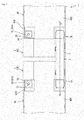
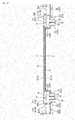
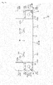
- FIG. 14 is a plan view of the bus bar 2 with cover in a state where the lid portions 53 are open
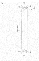
- FIG. 15 is a front view of the bus bar 2 with cover in a state where the lid portions 53 are open
- FIG. 16 is a side view of the bus bar 2 with cover in a state where the lid portions 53 are open.
- the main body portion 51 is a portion that covers the elongated bus bar main body portion 22 of the bus bar 21, and that is in the overall shape of a tube when being attached to the bus bar 21.
- the main body portion 51 includes an elongated tubular member 511, and two frame members 512 (512A and 512B) that are provided at respective ends of the tubular member 511.
- the tubular member 511 has a bottom portion 511A and a top portion 511B.
- the bottom portion 511A is a portion that mainly covers the lower face of the bus bar main body portion 22, and is in the shape of an elongated plate. Both edges in the longitudinal direction of the bottom portion 511A rise upward by a short distance. Of these, one of the edges is provided with two hinge portions 513.
- the bottom portion 511A is connected via the hinge portions 513 to the top portion 511B. Furthermore, the other edge is provided with two frame-shaped (ring-shaped) engagement portions 514.
- the top portion 511B is a portion that mainly covers the upper face of the bus bar main body portion 22, and is in the shape of an elongated plate as in the case of the bottom portion 511A. Both edges in the longitudinal direction of the top portion 511B rise upward by a short distance in a state where the bus bar cover 5 is unfolded as shown in FIG. 13 . Of these, one of the edges is provided with the above-described two hinge portions 513. Furthermore, the other edge is provided with two protrusion-like engageable portions 515 that are respectively engaged with the frame-shaped engagement portions 514.
- the hinge portions 513 are flexible, and, thus, they can be deformed in a bending manner. Accordingly, the top portion 511B and the bottom portion 511A that are connected to each other via the hinge portions 513 can move closer to or away from each other.
- the tubular member 511 When the top portion 511B is overlapped on the bottom portion 511A, the tubular member 511 is in the shape of a flat tube that enwraps the bus bar main body portion 22. Note that, when the engageable portions 515 provided on the top portion 511B are inserted into and engaged with the engagement portions 514 provided in the bottom portion 511A, the top portion 511B and the bottom portion 511A are fixed to each other. Furthermore, as shown in FIG. 14 , the ends 23 (23A and 23B) of the bus bar main body portion 22 are respectively exposed from both ends of the tubular member 511.
- the frame members 512 project outward respectively from both ends of the tubular member 511.
- the frame members 512 continue respectively from both ends of the bottom portion 511A.
- One of the frame members, denoted by 512A has a shape that surrounds the end 23A of the bus bar 21 when viewed from above, when the bus bar cover 5 is attached to the bus bar 21 as shown in FIG. 14 .
- the frame member 512A is disposed above the fixing portion 231 at the end 23A.
- the frame member 512A is substantially in the shape of a U when viewed from above.
- the frame member 512A is configured by two portions 512a and 512b that are arranged parallel to each other along the longitudinal direction of the tubular member 511, and a portion 512c that is disposed between the portions 512a and 512b.
- One of the two portions 512a and 512b, denoted by 512a, is provided with a hinge portion 52A.
- a lid portion 53A is attached via the hinge portion 52A to the frame member 512A.
- the other portion denoted by 512b, is provided with a protrusion-like engageable portion 54.
- the other frame member denoted by 512B, has the same shape as the above-described frame member 512A, and has a shape that surrounds the end 23B of the bus bar 21 when viewed from above, when the bus bar cover 5 is attached to the bus bar 21 as shown in FIG. 14 .
- the frame member 512B disposed above the fixing portion 231 at the end 23B.
- the frame member 512B is substantially in the shape of a U when viewed from above.
- the frame member 512B is configured by two portions 512a and 512b that are arranged parallel to each other along the longitudinal direction of the tubular member 511, and a portion 512c that is disposed between the portions 512a and 512b.
- One of the two portions 512a and 512b, denoted by 512a, is provided with a hinge portion 52B.
- a lid portion 53B is attached via the hinge portion 52B to the frame member 512B.
- the other portion denoted by 512b, is provided with a protrusion-like engageable portion 54.
- the ends 23 (23A and 23B) of the bus bar 21 are exposed from the main body portion 51 of the bus bar cover 5 when not being covered by the lid portions 53 (53A and 53B).
- the lid portions 53 are in the shape of plates that cover the opening portions inside the frame members 512 (512A and 512B). As described above, the lid portion 53A is connected via the hinge portion 52A to the frame member 512A. The end of the lid portion 53A is provided with a frame-shaped (ring-shaped) engagement portion 531 that engages with the protrusion-like engageable portion 54 provided on the frame member 512A. Meanwhile, the lid portion 53B is connected via the hinge portion 52B to the frame member 512B. The end of the lid portion 53B is provided with a frame-shaped (ring-shaped) engagement portion 531 that engages with the protrusion-like engageable portion 54 provided on the frame member 512B.
- the hinge portions 52 (52A and 52B) are flexible, and, thus, they can be deformed in a bending manner. Accordingly, the lid portions 53 (53A and 53B) that are connected via the hinge portions 52 (52A and 52B) to the frame members 512 (512A and 512B) can move closer to the frame members 512 (512A and 512B) so as to cover the ends 23 (23A and 23B) of the bus bar 21. Furthermore, the lid portions 53 (53A and 53B) can move away from the frame members 512 (512A and 512B) so as to expose the ends 23 (23A and 23B) of the bus bar 21. That is to say, the lid portions 53 (53A and 53B) can move (pivot) closer to the frame members 512 (512A and 512B) and away from the frame members 512 (512A and 512B).
- the lid portions 53 cover the opening portions inside the frame members 512
- the protrusion-like engageable portions 54 provided on the frame members 512 are inserted into the frame-shaped engagement portions 531 provided in the lid portions 53, and the engagement portions 531 and the engageable portions 54 engage with each other.
- the lid portions 53 are fixed to the frame members 512.
- the lid portions 53 are detachably fixed to the frame members 512 by means of the engagement portions 531 and the engageable portions 54.
- the bus bar cover 5 can be attached to the bus bar 21 in a state where the lid portions 53 (53A and 53B) are open. That is to say, the bus bar cover 5 can cover the portion other than the ends 23 (i.e., the bus bar main body portion 22) in a state where the ends 23 (23A and 23B) of the bus bar 21 are left exposed.
- the bus bar 21 including such a bus bar cover 5 i.e., the bus bar 2 with cover
- the reason thereof will be described.
- FIG. 17 is a plan view of the bus bar 2 with cover that has been attached to the first battery module 1A and the second battery module 1B in a state where the lid portions 53A and 53B are open.
- the ends of the bus bar 2 with cover are respectively placed on the adjacent electrode terminals 32A and 32B having opposite polarities respectively in the cell groups 3B and 3C.
- the lid portions 53A and 53B of the bus bar cover 5 attached to the bus bar 21 are both open, and the ends 23A and 23B of the bus bar 21 are exposed from the bus bar cover 5.
- the lid portions 53A and 53B of the bus bar 2 with cover are open in this manner, the positions of the ends 23A and 23B of the bus bar 21 can be easily checked. Accordingly, the ends 23A and 23B of the bus bar 21 1 can be easily placed on the electrode terminals 32A and 32B while checking the positions of the ends.
- the through holes 24 provided at the ends are positioned on the screw holes 33 provided in the electrode terminals 32A and 32B. Also at the time of performing this positioning, if the lid portions 53A and 53B of the bus bar 2 with cover are open, the positions of the through holes 24 and the positions of the screw holes 33 can be easily checked. Accordingly, the through holes 24 can be easily positioned on the screw holes 33.
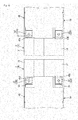
- FIG. 18 is a partial cross-sectional view of the battery module 1 including the bus bar 2 with cover taken along the line A-A' shown in FIG. 1 .
- a shank portion 62 of a fixing bolt 6 is inserted into the through hole 24 and the screw hole 33 that has been positioned under the through hole 24.
- a predetermined tool is placed on a head 61 provided at the end of the shank portion 62 and is used to rotate the fixing bolt 6. Accordingly, the shank portion 62 of the fixing bolt 6 is screwed into the screw hole 33 in a state where the head 61 presses the end 23 of the bus bar 21 against the electrode terminal 32.
- the ends 23 of the bus bar 21 are bolted by the fixing bolts 6 to the electrode terminals 32.
- the ends of the bus bar 2 with cover (the ends 23 of the bus bar 21) are fixed (i.e., bolted) to the electrode terminals 32 using the fixing bolts 6.
- the operation that attaches the fixing bolts 6 to the ends 23 of the bus bar 21 and to the electrode terminals 32 as described above is performed in a state where the lid portions 53A and 53B in the bus bar 2 with cover are open, for example, as shown in FIG. 17 .
- the operation that attaches the fixing bolts 6 is performed in a state where a tool (e.g., a hex wrench) is inserted into the frame members 512. Accordingly, if the lid portions 53 are open outward from the frame members 512 as shown in FIG. 17 , the tool can be prevented from being brought into contact with and interfering with the lid portions 53, for example. That is to say, even when the bus bar cover 5 is attached to the bus bar 21, the bus bar cover 5 does not interfere with the operation that attaches the fixing bolts 6 as long as the lid portions 53 are open.
- a tool e.g., a hex wrench
- the lid portions 53A and 53B of the bus bar cover 5 are closed as shown in FIG. 18 (or FIG. 1 ).
- the lid portions 53A and 53B are fixed to the frame members 512A and 512B. That is to say, the ends 23A and 23B of the bus bar 21 that have been exposed from the bus bar cover 5 up till then are respectively covered by the lid portions 53A and 53B from above. That is to say, the ends 23A and 23B of the bus bar 21 extending to link the first battery module 1A and the second battery module 1B are protected by the lid portions 53A and 53B. Accordingly, tools or the like can be prevented from being brought into contact with the ends 23A and 23B of the bus bar 21.
- the surfaces of the lid portions 53A and 53B are flush with the surface of the main body portion 51 (the top portion 511B of the tubular member 511). That is to say, the entire surface of the bus bar cover 5 is flat.
- the bus bar 2 with cover of this embodiment has the ends 23A and 23B of the bus bar 21 each of which projects downward in the shape of an L.
- the position of the head 61 of the fixing bolt 6 is set to be lower than the bus bar main body portion 22 of the bus bar 21. That is to say, the head 61 of the fixing bolt 6 is prevented from projecting to a position higher than the bus bar main body portion 22.
- the positions of the surfaces of the lid portions 53A and 53B can match the position of the surface of the main body portion 51 (the top portion 511B of the tubular member 511). Accordingly, the lid portions 53A and 53B of this embodiment are prevented from projecting to a position higher than the main body portion 51, and, thus, the lid portions 53A and 53B are prevented from interfering with objects and the like outside the battery module 1.
- the lid portions 53A and 53B are directly attached to the frame members 512A and 512B respectively via the hinge portions 52A and 52B. That is to say, the lid portions 53A and 53B are formed in one piece with the main body portion 51. Accordingly, there is no risk that the lid portions 53 are detached from the main body portion 51 and lost.
- the frame member 512A of the bus bar cover 5 is placed on the container-like portion of the resin protector 42A surrounding the opening portion 45B. Furthermore, the end 23A of the bus bar 21 is inserted into the container-like portion surrounding the opening portion 45B. Furthermore, the electrode terminal 32A is disposed so as to be exposed from the bottom side of the container-like portion surrounding the opening portion 45B. If the portion into which the end 23A of the bus bar 21 is inserted is in the shape of a container that surrounds the electrode terminal 32A in this manner, the L-shaped end 23A of the bus bar 21 is easily guided onto the electrode terminal 32A. That is to say, when the end 23A of the bus bar 21 is fitted to the container-like portion, the position of the end 23A of the bus bar 21 can substantially match that of the electrode terminal 32A.
- the rising portion 232 at the end 23A of the bus bar 21 is in contact with the peripheral wall of the container-like portion surrounding the opening portion 45. Furthermore, the fixing portion 231 at the end 23A, as well as the upper face of the electrode terminal 32A, is in contact with the bottom of the container-like portion surrounding the opening portion 45.
- the frame member 512A of the bus bar cover 5 is placed on the container-like portion of the resin protector 42B surrounding the opening portion 45B. Furthermore, the end 23B of the bus bar 21 is inserted into the container-like portion surrounding the opening portion 45B. Furthermore, the electrode terminal 32B is disposed so as to be exposed from the bottom side of the container-like portion surrounding the opening portion 45B. If the portion into which the end 23B of the bus bar 21 is inserted is in the shape of a container that surrounds the electrode terminal 32B in this manner, the L-shaped end 23B of the bus bar 21 is easily guided onto the electrode terminal 32B. That is to say, when the end 23B of the bus bar 21 is fitted to the container-like portion, the position of the end 23B of the bus bar 21 can substantially match that of the electrode terminal 32B.
- the rising portion 232 at the end 23B of the bus bar 21 is in contact with the peripheral wall of the container-like portion surrounding the opening portion 45. Furthermore, the fixing portion 231 at the end 23B, as well as the upper face of the electrode terminal 32B, is in contact with the bottom of the container-like portion surrounding the opening portion 45.
- the bus bar 2 with cover of this embodiment does not interfere with the attachment operation to the battery modules 1A and 1B as long as the lid portions 53A and 53B are open during the attachment operation. Furthermore, if the lid portions 53A and 53B are closed after the attachment operation, the ends of the bus bar 2 with cover are protected by the insulating material. Accordingly, the bus bar 2 with cover of this embodiment allows the attachment operation to the battery modules 1A and 1B to be easily performed, and, furthermore, the entire bus bar 21 is covered by the bus bar cover 5 after the attachment operation, so that the bus bar 2 with cover can be reliably protected by the insulating material.
- FIG. 19 is a plan view of a bus bar 2A with cover according to Embodiment 2.
- the bus bar 2A with cover of Embodiment 2 is formed by attaching a bus bar cover 5A to the bus bar 21 that is the same bus bar as in Embodiment 1.
- the bus bar cover 5A has the same basic configuration as that of the bus bar cover 5 of Embodiment 1. Note that the bus bar cover 5A of this embodiment does not include the engagement portions 531 and the engageable portions 54, which are included in the bus bar cover 5 of Embodiment 1.
- the lid portions 53A and 53B are respectively attached to the frame members 512A and 512B using an adhesive tape or the like. In this manner, the lid portions 53A and 53B may be respectively attached to the frame members 512A and 512B using an adhesive tape or the like.
Landscapes
- Chemical & Material Sciences (AREA)
- Chemical Kinetics & Catalysis (AREA)
- Electrochemistry (AREA)
- General Chemical & Material Sciences (AREA)
- Inorganic Chemistry (AREA)
- Connection Of Batteries Or Terminals (AREA)
Abstract
Description
- The present invention relates to a bus bar cover, and a bus bar with cover.
- Battery modules for automobiles such as electric automobiles or hybrid automobiles include a cell group in which a plurality of cells are arranged in a row. Each of the cells forming the cell group has a positive electrode terminal and a negative electrode terminal, and the electrode terminals having opposite polarities respectively included in adjacent cells are electrically connected by a metal bus bar.
- The bus bar is attached to each pair of such electrode terminals at a plurality of locations on the cell group. Such a bus bar is used to electrically connect the cells forming the cell group in series.
- If the bus bar is attached to each pair of electrode terminals in the cell group, the attachment operation takes much time. Accordingly, a battery wiring module is used that can simultaneously position a plurality of bus bars on the respective pairs of electrode terminals as shown in
Patent Document 1 and so on. This sort of battery wiring module is configured such that a plurality of bus bars are held by an insulating substrate made of a resin or the like, and is placed on and fixed to the cell group. - If the number of cells contained in a cell group is too large, attachment errors and the like of the electrode terminals may accumulate, and pitches between the electrode terminals having opposite polarities may be larger or smaller than the allowable range. If the above-described battery wiring module is used in this state, it may be rather difficult to attach the bus bars to the respective pairs of electrode terminals. Accordingly, in the above-described battery module, all cells may not be treated as one cell group, but they may be used in a state of being divided into a plurality of cell groups. Furthermore, the cells may be divided into a plurality of cell groups also due to limitations of space in which the battery module is to be installed, for example.
- Note that the plurality of cell groups are electrically connected to each other by dedicated bus bars. Both ends of this sort of bus bar are fixed by bolting or the like respectively to electrode terminals having opposite polarities. The bus bar extends to link the cell groups in a state where both ends are fixed.
- Patent Document 1:
JP 2011-8957A - If the bus bar extending to link the cell groups is left exposed, tools or the like may be brought into contact with the bus bar, which may result in a short-circuit of the battery module. Accordingly, it is conceivable to cover the bus bar with an insulating material. However, the ends of the bus bar have to be exposed, at least during the attachment operation of the bus bar, in order to avoid interference with the attachment operation. Preferably, the ends of the bus bar are also covered by an insulating material after the bus bar is attached between the cell groups.
- However, there is no known technique for covering the bus bar with an insulating material while satisfying these requests, which is problematic.
- The present invention was made in view of these circumstances, and it is an object thereof to provide a technique for covering, with an insulating material, a bus bar for electrically connecting cell groups, wherein ends of the bus bar can be exposed from the insulating material during attachment of the bus bar between the cell groups, and the ends of the bus bar can be covered by the insulating material after attachment of the bus bar between the cell groups.
- The present invention is directed to an insulating bus bar cover that is attachable to a bus bar between a cell group in which a plurality of cells including a pair of positive and negative electrode terminals are arranged in a row and a cell group of the same type adjacent to said cell group, both ends of the bus bar being respectively fixable to electrode terminals having opposite polarities in order to electrically connect the electrode terminals, the bus bar cover including: a main body portion for covering the bus bar while exposing both ends of the bus bar; hinge portions that are provided at ends of the main body portion; and lid portions that are attached via the hinge portions to the main body portion, and are pivotable by the hinge portions so as to cover or expose the ends of the bus bar. Since the bus bar cover has this configuration, the ends of the bus bar can be exposed from or covered by the bus bar cover as necessary.
- The bus bar cover preferably further includes engagement portions that are provided at the lid portions; and engageable portions that are provided at the ends of the main body portion, wherein engagement of the engageable portions with the engagement portions fixes the lid portions in a state where the lid portions cover the ends of the bus bar. Since the bus bar cover includes the engagement portions and the engageable portions, the lid portions are fixed in a state where they cover the ends of the bus bar.
- The bus bar cover is preferably configured such that the main body portion includes: a tubular member for covering the bus bar while exposing both ends of the bus bar; and frame members that are provided at ends of the tubular member, and surround the ends of the bus bar exposed from the tubular member; and the hinge portions and the engageable portions are provided on the frame members.
- The bus bar cover may be configured such that the tubular member includes a bottom portion that covers a lower face of the bus bar and a top portion that covers an upper face of the bus bar, and the bottom portion and the top portion are detachably attached to the bus bar. Since the tubular member is detachably attached to the bus bar, the bus bar cover can be attached later to the bus bar.
- The bus bar cover may be configured such that the ends of the bus bar respectively include a fixing portion that can be placed on the electrode terminals and fixed to the electrode terminals, and a rising portion that rises from the fixing portion. Since the ends of the bus bar include the fixing portions and the rising portions, positioning with respect to the electrode terminals that are to be fixed to the fixing portions can be easily performed.
- The present invention is directed to a bus bar with a cover, including: a bus bar that is fixable between a cell group in which a plurality of cells including a pair of positive and negative electrode terminals are arranged in a row and a cell group of the same type adjacent to said cell group, both ends of the bus bar being respectively fixable to electrode terminals having opposite polarities in order to electrically connect the electrode terminals; and an insulating bus bar cover that is attachable to the bus bar, and includes: a main body portion for covering the bus bar while exposing both ends of the bus bar, hinge portions that are provided at ends of the main body portion, and lid portions that are attached via the hinge portions to the main body portion, and are pivotable by the hinge portions so as to cover or expose the ends of the bus bar.
- The present invention can provide a technique for covering, with an insulating material, a bus bar for electrically connecting cell groups, wherein ends of the bus bar can be exposed from the insulating material during attachment of the bus bar between the cell groups, and the ends of the bus bar can be covered by the insulating material after attachment of the bus bar between the cell groups.
-
- [
FIG. 1] FIG. 1 is a plan view of a battery module including a bus bar with cover according to Embodiment 1. - [
FIG. 2] FIG. 2 is a plan view of cell groups. - [
FIG. 3] FIG. 3 is a plan view of a first battery wiring module. - [
FIG. 4] FIG. 4 is a plan view of a first connection member. - [
FIG. 5] FIG. 5 is a plan view of a second connection member. - [
FIG. 6] FIG. 6 is a plan view of coupling units forming a resin protector. - [
FIG. 7] FIG. 7 is a plan view of the first battery wiring module placed on the cell groups. - [
FIG. 8] FIG. 8 is a plan view of a first battery module. - [
FIG. 9] FIG. 9 is a plan view of a second battery wiring module placed on cell groups. - [
FIG. 10] FIG. 10 is a plan view of a first battery module and a second battery module that are adjacent to each other with a gap interposed therebetween. - [
FIG. 11] FIG. 11 is a plan view of a bus bar. - [
FIG. 12] FIG. 12 is a side view of the bus bar. - [
FIG. 13] FIG. 13 is a plan view of a bus bar cover in an unfolded state. - [
FIG. 14] FIG. 14 is a plan view of the bus bar with cover in a state where lid portions are open. - [
FIG. 15] FIG. 15 is a front view of the bus bar with cover in a state where the lid portions are open. - [
FIG. 16] FIG. 16 is a side view of the bus bar with cover in a state where the lid portions are open. - [
FIG. 17] FIG. 17 is a plan view of the bus bar with cover that has been attached to the first battery module and the second battery module in a state where the lid portions are open. - [
FIG. 18] FIG. 18 is a partial cross-sectional view of the battery module including the bus bar with cover taken along the line A-A' shown inFIG. 1 . - [
FIG. 19] FIG. 19 is a plan view of a bus bar with cover according to Embodiment 2. - Hereinafter,
Embodiment 1 of the present invention will be described with reference toFIGS. 1 to 18 .FIG. 1 is a plan view of abattery module 1 including abus bar 2 with cover according to Embodiment 1. Thebattery module 1 shown inFIG. 1 is used as a drive source for automobiles such as electric automobiles and hybrid automobiles. As shown inFIG. 1 , thebattery module 1 is configured by afirst battery module 1A and asecond battery module 1B that are connected to each other via thebus bar 2 with cover. InFIG. 1 , thefirst battery module 1A is shown on the left side, and thesecond battery module 1B is shown on the right side. The lower side inFIG. 1 corresponds to the front side (the front face side) of thebattery module 1, and the upper side inFIG. 1 corresponds to the rear side (the rear face side) of thebattery module 1. Furthermore, the left-right direction inFIG. 1 corresponds to the left-right direction of thebattery module 1. - First, one of the battery modules, denoted by 1A, will be described with reference to
FIGS. 1 to 8 . Thefirst battery module 1A includes twocell groups 3, a firstbattery wiring module 4A fixed to thecell groups 3, and acover 43A for the firstbattery wiring module 4A, which is placed on the firstbattery wiring module 4A. -
FIG. 2 is a plan view of thecell groups 3.FIG. 2 shows fourcell groups cell groups first battery module 1A, and thecell groups second battery module 1B (described later). - As shown in
FIG. 2 , each of the cell groups 3 (3A, 3B, 3C, and 3D) is configured by fourcells 31 that are stacked in a row. The cell groups 3 (3A, 3B, 3C, and 3D) are arranged side by side with a gap interposed therebetween along the left-right direction shown inFIG. 2 . In this embodiment, the gap between thecell group 3B used for thefirst battery module 1A and thecell group 3C used for thesecond battery module 1B is set to be larger than the gap between theother cell groups 3. - Each
cell 31 forming thecell groups 3 internally includes an electricity generating element (not shown). Thecell 31 includes amain body portion 31a in the shape of a flat rectangular solid internally including the electricity generating element, and two electrode terminals 32 (32A and 32B) that are provided on an upper face of themain body portion 31a. One of the electrode terminals, denoted by 32A, is a positive electrode, and the other electrode terminal, denoted by 32B, is a negative electrode. - The
electrode terminals main body portions 31a). Each of the electrode terminals 32 (32A and 32B) is configured by a nut in the shape of a square tube, and around screw hole 33 is formed through the center of the nut. - The
cells 31 forming thecell groups 3 are arranged such that their electrode terminals 32 (32A and 32B) face in the same direction (upward). Thecells 31 in thecell groups 3 are arranged such that theadjacent electrode terminals 32 of theadjacent cells 31 have opposite polarities. That is to say, the positive andnegative electrode terminals 32 are alternately arranged in the direction in which thecells 31 are stacked in a row (the front-rear direction of the cell groups 3). - Also, the
cell groups first battery module 1A are arranged such that theadjacent electrode terminals 32 of theadjacent cells 31 respectively in thedifferent cell groups - Furthermore, the
cell group 3B used for thefirst battery module 1A and thecell group 3C used for thesecond battery module 1B are arranged such that theadjacent electrode terminals 32 of theadjacent cells 31 respectively in thedifferent cell groups - The electrode terminals 32 (32A and 32B) of the
cell groups first battery module 1A are arranged on the same plane. The cell groups 3 (3A, 3B, 3C, and 3D) are placed on and fixed to a holding plate (not shown) that is disposed on the lower faces of thecells 31. -
FIG. 3 is a plan view of the firstbattery wiring module 4A. The firstbattery wiring module 4A is placed on the upper faces of thecell groups cell groups cell groups battery wiring module 4A. This firstbattery wiring module 4A mainly includes a plurality ofconnection members 41, and aresin protector 42A in the shape of a container that accommodates theconnection members 41. - The
connection members 41 are formed by processing a metal material such as copper, copper alloy, stainless steel (SUS), or aluminum, into a predetermined shape. Theconnection members 41 each have a substantially elongated (belt-like) shape, and are configured as members generally known as bus bars. In this embodiment, two types of connection members having different lengths are used as theconnection members 41. Of these, the longer ones are referred to asfirst connection members 41A, and the shorter ones are referred to assecond connection members 41B.FIG. 4 is a plan view of thefirst connection member 41A. As shown inFIG. 4 , thefirst connection member 41A includes an elongated main body portion 141 (141A), throughholes 48 through which shank portions of fixing bolts are inserted respectively at both ends in the longitudinal direction of the main body portion 141 (141A), and cut-outportions 49 that sandwich the throughhole 48 at each end of the main body portion 141 (141A). -
FIG. 5 is a plan view of thesecond connection member 41B. As shown inFIG. 5 , thesecond connection member 41B has the same basic configuration as that of thefirst connection member 41A although the length is shorter than that of thefirst connection member 41A. Specifically, thesecond connection member 41B includes an elongated main body portion 141 (141B), throughholes 48 through which shank portions of fixing bolts are inserted respectively at both ends in the longitudinal direction of the main body portion 141 (141B), and cut-outportions 49 that sandwich the throughhole 48 at each end of the main body portion 141 (141B). - The
connection members 41 extend to link theelectrode terminals cell groups 3. Thecells 31 forming the cell groups 3 (3A and 3B) are connected in series by theconnection members 41. Thefirst connection member 41A is used to electrically connect theelectrode terminals adjacent cells 31 respectively in thecell groups second connection member 41B is used to electrically connect theelectrode terminals cells 31 that are adjacent to each other in the direction in which they are stacked in a row (the front-rear direction), in each of thecell groups connection members 41 are used in a state where they are held by theresin protector 42A (seeFIG. 3 ). - The ends of the
connection members 41 are placed on theelectrode terminals 32 and are fixed to theelectrode terminals 32. At that time, the position of the throughhole 48 at each end of eachconnection member 41 is set to the position of thescrew hole 33 of the correspondingelectrode terminal 32. Then, a shank portion of a fixing bolt (not shown) is inserted into the throughhole 48 of theconnection member 41 and thescrew hole 33 of theelectrode terminal 32, and the fixing bolt is screwed into thescrew hole 33 such that theconnection member 41 and theelectrode terminal 32 are in close contact with each other. - Note that the through
hole 48 provided in theconnection member 41 is in the shape of a so-called elongated hole when viewed from above, and is set to be larger than thescrew hole 33 of theelectrode terminal 32. Furthermore, the throughhole 48 is elongated in the longitudinal direction of theconnection member 41. Since theconnection member 41 includes such an elongated throughhole 48, the throughhole 48 of theconnection member 41 can be positioned on thescrew hole 33 of theelectrode terminal 32 such that the fixing bolt can be inserted into these holes even if the position of theelectrode terminal 32 is dislocated from the position where it should be. Note that such a dislocation of theelectrode terminals 32 is caused by, for example, attachment errors of theelectrode terminals 32 on thecells 31, deformation such as swelling of thecells 31, or errors in the arrangement pitches in thecell groups - The plurality of
connection members 41 form a predetermined pattern in the container-like resin protector 42A (seeFIG. 3 ). Thefirst connection members 41A are arranged along the left-right direction inFIG. 3 . Meanwhile, thesecond connection members 41B are arranged along the vertical direction inFIG. 3 . That is to say, thefirst connection members 41A and thesecond connection members 41B are arranged along directions that are perpendicular to each other. - The
resin protector 42A is formed by processing an insulating composite resin material into a predetermined shape.FIG. 6 is a plan view of coupling units 42A1, 42A2, 42A3, and 42A4 forming theresin protector 42A. Theresin protector 42A of this embodiment is formed by combining the four coupling units 42A1, 42A2, 42A3, and 42A4 shown inFIG. 6 . - The coupling unit 42A1 is combined with the coupling unit 42A2. The coupling units 42A1 and 42A2 form two connection member accommodating portions 43 (43A) that accommodate the
first connection members 41A. The connection member accommodating portions 43 (43A) are each in the shape of a small container that extends along the left-right direction inFIG. 6 , inside of which thefirst connection member 41A is held. Furthermore, the connection member accommodating portions 43 (43A) can be extended and retracted along the longitudinal direction of thefirst connection members 41A. - The connection member accommodating portion 43 (43A) includes an elongated bottom plate portion on which the
first connection member 41A is placed, and a peripheral wall portion in the shape of a square tube that surrounds the bottom plate portion. Each of the bottom plate portion and the peripheral wall portion is divided between the coupling unit 42A1 side and the coupling unit 43A2 side. Both ends in the longitudinal direction of the bottom plate portion are respectively provided with openingportions 44. At the openingportions 44, the ends of thefirst connection member 41A are exposed from the connection member accommodating portion 43 (43A) so as to allow contact with theelectrode terminals 32. - The inner face of the peripheral wall portion is provided with a plurality of restricting
protrusions 46 that restrict upward movement of thefirst connection member 41A in the thickness direction (in the upper direction). The restrictingprotrusions 46 are shaped so as to project from the inner face of the peripheral wall portion, and press thefirst connection member 41A from its upper face side to the bottom plate portion side. The inner face of the peripheral wall portion is further provided with a plurality ofengagement protrusions 47 that respectively engage with the cut-outportions 49 of thefirst connection member 41A. As shown inFIG. 3 , theengagement protrusions 47 are shaped so as to project from the inner face of the peripheral wall portion, and extend along the longitudinal direction of thefirst connection member 41A. Furthermore, theengagement protrusions 47 are each set to be smaller than the cut-outportion 49, and a gap is provided in advance between both ends in the longitudinal direction of theengagement protrusion 47 and the cut-outportion 49. - The coupling unit 42A1 side of the connection member accommodating portion 43 (43A) can move in the left-right direction in
FIG. 3 along the longitudinal direction of thefirst connection member 41A, within a range in which theengagement protrusions 47 can move inside the cut-outportions 49. In a similar manner, the coupling unit 42A2 side of the connection member accommodating portion 43 (43A) also can move in the left-right direction along the longitudinal direction of thefirst connection member 41A, within a range in which theengagement protrusions 47 can move inside the cut-outportions 49. In this manner, the connection member accommodating portions 43 (43A) can be extended and retracted (i.e., can slide) along the longitudinal direction of thefirst connection members 41A. - Furthermore, the coupling unit 42A3 is combined with the coupling unit 42A4. The coupling units 42A3 and 42A4 form two connection member accommodating portions 43 (43A) that accommodate the
first connection members 41A. The connection member accommodating portions 43 (43A) configured by the coupling units 42A3 and 42A4 have a basic configuration similar to that of the above-described connection member accommodating portions 43 (43A) configured by the two coupling units 42A1 and 42A2. The connection member accommodating portions 43 (43A) configured by the coupling units 42A3 and 42A4 also can be extended and retracted (i.e., can slide) along the longitudinal direction of thefirst connection members 41A. - Furthermore, the above-described coupling unit 42A1 is combined also with the coupling unit 42A3. The coupling units 42A1 and 42A3 form one connection member accommodating portion 43 (43B) that accommodates the
second connection member 41B. The connection member accommodating portions 43 (43B) is in the shape of a small container that extends along the vertical direction inFIG. 6 , inside of which thesecond connection member 41B is held. Furthermore, the connection member accommodating portion 43 (43B) can be extended and retracted along the longitudinal direction of thesecond connection member 41B. - The connection member accommodating portion 43 (43B) includes an elongated bottom plate portion on which the
second connection member 41B is placed, and a peripheral wall portion in the shape of a square tube that surrounds the bottom plate portion. Each of the bottom plate portion and the peripheral wall portion is divided between the coupling unit 42A1 side and the coupling unit 42A3 side. Both ends in the longitudinal direction of the bottom plate portion are respectively provided with openingportions 44. At the openingportions 44, the ends of thesecond connection member 41B are exposed from the connection member accommodating portion 43 (43B) so as to allow contact with theelectrode terminals 32. - The inner face of the peripheral wall portion is provided with a plurality of restricting
protrusions 46 that restrict upward movement of thesecond connection member 41B in the thickness direction (in the upper direction). The restrictingprotrusions 46 are shaped so as to project from the inner face of the peripheral wall portion, and press thesecond connection member 41B from its upper face side to the bottom plate portion side. The inner face of the peripheral wall portion is further provided with a plurality ofengagement protrusions 47 that respectively engage with the cut-outportions 49 of thesecond connection member 41B. As shown inFIG. 3 , theengagement protrusions 47 are shaped so as to project from the inner face of the peripheral wall portion, and extend along the longitudinal direction of thesecond connection member 41B. Furthermore, theengagement protrusions 47 are each set to be smaller than the cut-outportion 49, and a gap is provided in advance between both ends in the longitudinal direction of theengagement protrusion 47 and the cut-outportion 49. - The coupling unit 42A1 side of the connection member accommodating portion 43 (43B) can move in the vertical direction in
FIG. 3 along the longitudinal direction of thesecond connection member 41B, within a range in which theengagement protrusions 47 can move inside the cut-outportions 49. In a similar manner, the coupling unit 42A3 side of the connection member accommodating portion 43 (43B) also can move in the vertical direction inFIG. 3 along the longitudinal direction of thesecond connection member 41B, within a range in which theengagement protrusions 47 can move inside the cut-outportions 49. In this manner, the connection member accommodating portion 43 (43B) can be extended and retracted (i.e., can slide) along the longitudinal direction of thesecond connection member 41B. - Furthermore, the coupling unit 42A2 is combined also with the coupling unit 42A4. The coupling units 42A2 and 42A4 form one connection member accommodating portion 43 (43B) that accommodates the
second connection member 41B. The connection member accommodating portion 43 (43B) configured by the coupling units 42A2 and 42A4 has a basic configuration similar to that of the above-described connection member accommodating portion 43 (43B) configured by the coupling units 42A1 and 42A3. The connection member accommodating portion 43 (43B) configured by the coupling units 42A2 and 42A4 also can be extended and retracted (i.e., can slide) along the longitudinal direction of thesecond connection member 41B. - Note that the coupling unit 42A3 is provided with a connection member accommodating portion 43 (43C) that accommodates the
second connection member 41B. The connection member accommodating portion 43 (43C) is not extended or retracted along the longitudinal direction of thesecond connection member 41B, but includes a bottom plate portion and a peripheral wall portion that surrounds the bottom plate portion as in the case of the connection member accommodating portion 43 (43B). Furthermore, the connection member accommodating portion 43 (43C) includes the openingportions 44, theengagement protrusions 47, and the like, as in the case of the connection member accommodating portion 43 (43B). - Furthermore, the coupling unit 42A2 and the coupling unit 42A4 are respectively provided with opening
portions electrode terminals 32 that are positioned at the ends of thecells 31 connected in series when the firstbattery wiring module 4A is placed on thecell groups portions cell 31 that is at the rearmost of thecell group 3B is exposed from theopening portion 45A of the coupling unit 42A2. Meanwhile, the electrode terminal 32 (32A) of thecell 31 that is at the frontmost of thecell group 3B is exposed from theopening portion 45B of the coupling unit 42A4. In this embodiment, theopening portion 45B is set to be larger than the openingportion 45A. - This
resin protector 42A can be deformed so as to be extended or retracted (extending and retracting deformation) to some extent in each of the left-right direction (the longitudinal direction of thefirst connection members 41A) and the front-rear direction (the longitudinal direction of thesecond connection members 41B) in accordance with e.g., a dislocation of the ends of theconnection members 41 and theelectrode terminals 32, which may be caused by attachment errors of theelectrode terminals 32 or the like. Note that theresin protector 42A can be regarded on the whole as including onebottom plate 401 and aperipheral wall 402 in the shape of a flat square tube that surrounds thebottom plate 401. - The
resin protector 42A accommodates, in addition to theconnection members 41, a plurality of voltage detection terminals (not shown) for detecting the voltage of thecells 31. The voltage detection terminals are placed on therespective connection members 41, and voltage detection electrical wires (not shown) are respectively connected to the voltage detection terminals by pressure bonding or the like. Note that these voltage detection electrical wires are connected to a battery ECU (not shown). The battery ECU has a microcomputer, devices, and the like mounted therein, and has a well-known configuration including the functions for detecting voltages, currents, temperatures, and the like of thecells 31, or for controlling charge and discharge of thecells 31, for example. - The
peripheral wall 402 of the resin protector 42 is provided with a plurality of protrusion-like engagement portions 403. Theengagement portions 403 are provided on theperipheral wall 402 along the long sides of the resin protector 42. Theengagement portions 403 are used when attaching thecover 43A to theresin protector 42A. -
FIG. 7 is a plan view of the firstbattery wiring module 4A that has been placed on thecell groups FIG. 7 , the firstbattery wiring module 4A is placed on and fixed to the upper faces of the twocell groups cell groups battery wiring module 4A. That is to say, thecells 31 contained in the twocell groups battery wiring module 4A. -
FIG. 8 is a plan view of thefirst battery module 1A. Thefirst battery module 1A shown inFIG. 8 includes thecover 43A for the firstbattery wiring module 4A. Thecover 43A is attached to the firstbattery wiring module 4A (theresin protector 42A) so as to cover theconnection members 41 and the like in theresin protector 42A. Thecover 43A is substantially in the shape of a rectangle elongated in the left-right direction when viewed from above. In order to prevent tools or the like from being brought into contact with theconnection members 41 and causing a short-circuit of the battery module 1 (thefirst battery module 1A), for example, thecover 43A is detachably attached to theresin protector 42A so as to cover the opening of the container-like resin protector 42A (portion surrounded by the upper end of the peripheral wall 402). Thecover 43A as well as theresin protector 42A is made of an insulating composite resin material. Thecover 43A includes a covermain body portion 143A in the shape of a plate, and a plurality ofengageable portions 404 that are provided on the edges along the long sides of the covermain body portion 143A. Each of theengageable portions 404 is frame-shaped, and the protrusion-like engagement portions 403 provided on theresin protector 42A are inserted into theengageable portions 404. Theengagement portions 403 and theengageable portions 404 engage with each other, and, thus, thecover 43A is attached to theresin protector 42A. - As shown in
FIG. 8 , the right end of thecover 43A has a longer portion only at the center, so that part of the firstbattery wiring module 4A is exposed without being covered by thecover 43A. At these exposed portions, the two openingportions resin protector 42A are respectively arranged, and the electrode terminals 32 (32B and 23A) are respectively exposed from the openingportions - Next, the
second battery module 1B will be described with reference toFIGS. 1 and9. FIG. 9 is a plan view of a secondbattery wiring module 4B that has been placed on thecell groups FIG. 1 , thesecond battery module 1B is used together with thefirst battery module 1A. Thesecond battery module 1B is similar to the above-describedfirst battery module 1A, and thesecond battery module 1B has a basic configuration similar to that of thefirst battery module 1A. A battery module obtained by rotating by 180° thefirst battery module 1A shown inFIG. 1 is substantially the same as thesecond battery module 1B shown inFIG. 1 . Thesecond battery module 1B includes twocell groups battery wiring module 4B fixed to thecell groups cover 43B for the secondbattery wiring module 4B, which is placed on the secondbattery wiring module 4B. Thecover 43B has the same basic configuration as that of thecover 43A. - The second
battery wiring module 4B has substantially the same basic configuration as that of the firstbattery wiring module 4A. Note that the structure of aresin protector 42B included in the secondbattery wiring module 4B is partially different from that of theresin protector 42A. Specifically, the positions of the two openingportions resin protector 42B are reversed from those in theresin protector 42A. - As shown in
FIG. 9 , the secondbattery wiring module 4B is placed on and fixed to the upper faces of the twocell groups cell groups battery wiring module 4B. That is to say, thecells 31 contained in the twocell groups battery wiring module 4B. - The electrode terminal 32 (32A) of the
cell 31 that is at the rearmost of thecell group 3C is exposed from theopening portion 45A of theresin protector 42B. Meanwhile, the electrode terminal 32 (32B) of thecell 31 that is at the frontmost of thecell group 3C is exposed from theopening portion 45B of theresin protector 42B. -
FIG. 10 is a plan view of thefirst battery module 1A and thesecond battery module 1B that are adjacent to each other with a gap interposed therebetween. As shown inFIG. 10 , thefirst battery module 1A and thesecond battery module 1B are arranged side by side with a predetermined gap interposed therebetween such that thecell group 3B side of thefirst battery module 1A and thecell group 3C side of thesecond battery module 1B face each other. The two exposed electrode terminals 32 (32B and 32A) in thefirst battery module 1A and the two exposed electrode terminals 32 (32A and 32B) in thesecond battery module 1B are positioned close to each other. - As shown in
FIG. 10 , theelectrode terminal 32B exposed from theopening portion 45A of thefirst battery module 1A is adjacent to theelectrode terminal 32A exposed from theopening portion 45A of thesecond battery module 1B. Theadjacent electrode terminals cell groups - Furthermore, as shown in
FIG. 10 , theelectrode terminal 32A exposed from theopening portion 45B of thefirst battery module 1A is adjacent to theelectrode terminal 32B exposed from theopening portion 45B of thesecond battery module 1B. Theadjacent electrode terminals cell groups bus bar 2 with cover as shown inFIG. 1 . - Next, the structure of the
bus bar 2 with cover will be described with reference toFIGS. 11 to 16 . Thebus bar 2 with cover is formed by attaching abus bar cover 5 to abus bar 21. Thecell groups first battery module 1A and thecell groups second battery module 1B are electrically connected to each other (connected in series) by thebus bar 21 included in thebus bar 2 with cover. -
FIG. 11 is a plan view of thebus bar 21, andFIG. 12 is a side view of thebus bar 21. As shown inFIG. 11 , thebus bar 21 has a substantially elongated (belt-like) overall shape. Thebus bar 21 is formed by processing (e.g., punching, or bending) a plate material made of metal such as copper, copper alloy, stainless steel (SUS), or aluminum, into a predetermined shape. Thebus bar 21 extends to link thefirst battery module 1A and thesecond battery module 1B, and is used to electrically connect these battery modules. Note that thebus bar 21 of this embodiment is larger (longer) than the above-describedconnection member 41 used for the firstbattery wiring module 4A and the like. - The
bus bar 21 includes a bus barmain body portion 22 and a pair of ends 23 (23A and 23B) that sandwich the bus barmain body portion 22. The ends 23 (23A and 23B) are respectively provided with throughholes 24. - The bus bar
main body portion 22 is configured by an elongated plate-like portion that extends in a straight line. Both ends of the bus barmain body portion 22 respectively continue to the ends 23 (23A and 23B) each of which is configured by an L-shaped plate material when viewed from the side. Eachend 23 is configured by aflat fixing portion 231 and a risingportion 232 that continues from the fixingportion 231. - The fixing
portion 231 is placed on theelectrode terminal 32 and is fixed to theelectrode terminal 32. The fixingportion 231 is substantially rectangular, but has rounded corners as shown inFIG. 11 . Furthermore, the fixingportion 231 is provided with the above-described throughhole 24. As shown inFIG. 11 , the throughhole 24 is in the shape of a so-called elongated hole when viewed from above, and is elongated in the longitudinal direction of the bus barmain body portion 22. The throughhole 24 is set to be larger than thescrew hole 33 of theelectrode terminal 32 included in thebattery modules hole 24 is formed by performing a known punching process on a plate material made of metal such as those described above. The fixingportion 231 is disposed parallel to the bus barmain body portion 22. - The rising
portion 232 rises upward from the fixingportion 231. The upper end of the risingportion 232 is connected to the bus barmain body portion 22. The risingportion 232 is disposed perpendicular to the bus barmain body portion 22 and the fixingportion 231. - Various conditions of the
bus bar 21 such as the length of the bus barmain body portion 22, the height of the rising portion 232 (the height from the fixing portion 231), and the size of the fixingportion 231 are set as appropriate, for example, in accordance with the shapes of thefirst battery module 1A and thesecond battery module 1B to which the bus bar is to be attached. In this embodiment, theend 23A shown in the left inFIGS. 11 and12 and theend 23B shown in the right are set to have the same shape. - The
bus bar cover 5 is formed by processing an insulating composite resin material into a predetermined shape.FIG. 13 is a plan view of thebus bar cover 5 in an unfolded state. Thebus bar cover 5 of this embodiment is detachably attached to thebus bar 21. Thebus bar cover 5 that has been attached to thebus bar 21 is in the overall shape of a tube. On the other hand, thebus bar cover 5 before the attachment can be unfolded and opened flat as shown inFIG. 13 . - As shown in
FIG. 13 , thebus bar cover 5 includes amain body portion 51,hinge portions 52 that are provided at the ends of themain body portion 51, andlid portions 53 that are attached via thehinge portions 52 to themain body portion 51.FIG. 14 is a plan view of thebus bar 2 with cover in a state where thelid portions 53 are open,FIG. 15 is a front view of thebus bar 2 with cover in a state where thelid portions 53 are open, andFIG. 16 is a side view of thebus bar 2 with cover in a state where thelid portions 53 are open. - As shown in
FIG. 14 and so on, themain body portion 51 is a portion that covers the elongated bus barmain body portion 22 of thebus bar 21, and that is in the overall shape of a tube when being attached to thebus bar 21. Themain body portion 51 includes anelongated tubular member 511, and two frame members 512 (512A and 512B) that are provided at respective ends of thetubular member 511. - As shown in
FIG. 13 , thetubular member 511 has abottom portion 511A and atop portion 511B. Thebottom portion 511A is a portion that mainly covers the lower face of the bus barmain body portion 22, and is in the shape of an elongated plate. Both edges in the longitudinal direction of thebottom portion 511A rise upward by a short distance. Of these, one of the edges is provided with twohinge portions 513. Thebottom portion 511A is connected via thehinge portions 513 to thetop portion 511B. Furthermore, the other edge is provided with two frame-shaped (ring-shaped)engagement portions 514. - The
top portion 511B is a portion that mainly covers the upper face of the bus barmain body portion 22, and is in the shape of an elongated plate as in the case of thebottom portion 511A. Both edges in the longitudinal direction of thetop portion 511B rise upward by a short distance in a state where thebus bar cover 5 is unfolded as shown inFIG. 13 . Of these, one of the edges is provided with the above-described twohinge portions 513. Furthermore, the other edge is provided with two protrusion-likeengageable portions 515 that are respectively engaged with the frame-shapedengagement portions 514. - The
hinge portions 513 are flexible, and, thus, they can be deformed in a bending manner. Accordingly, thetop portion 511B and thebottom portion 511A that are connected to each other via thehinge portions 513 can move closer to or away from each other. - When the
top portion 511B is overlapped on thebottom portion 511A, thetubular member 511 is in the shape of a flat tube that enwraps the bus barmain body portion 22. Note that, when theengageable portions 515 provided on thetop portion 511B are inserted into and engaged with theengagement portions 514 provided in thebottom portion 511A, thetop portion 511B and thebottom portion 511A are fixed to each other. Furthermore, as shown inFIG. 14 , the ends 23 (23A and 23B) of the bus barmain body portion 22 are respectively exposed from both ends of thetubular member 511. - The frame members 512 (512A and 512B) project outward respectively from both ends of the
tubular member 511. In this embodiment, the frame members 512 (512A and 512B) continue respectively from both ends of thebottom portion 511A. One of the frame members, denoted by 512A, has a shape that surrounds theend 23A of thebus bar 21 when viewed from above, when thebus bar cover 5 is attached to thebus bar 21 as shown inFIG. 14 . Moreover, as shown inFIG. 15 , theframe member 512A is disposed above the fixingportion 231 at theend 23A. Theframe member 512A is substantially in the shape of a U when viewed from above. Theframe member 512A is configured by twoportions tubular member 511, and aportion 512c that is disposed between theportions portions hinge portion 52A. Alid portion 53A is attached via thehinge portion 52A to theframe member 512A. Furthermore, the other portion, denoted by 512b, is provided with a protrusion-likeengageable portion 54. - Furthermore, the other frame member, denoted by 512B, has the same shape as the above-described
frame member 512A, and has a shape that surrounds theend 23B of thebus bar 21 when viewed from above, when thebus bar cover 5 is attached to thebus bar 21 as shown inFIG. 14 . Moreover, as shown inFIG. 15 , theframe member 512B disposed above the fixingportion 231 at theend 23B. Theframe member 512B is substantially in the shape of a U when viewed from above. As in the case of theframe member 512A, theframe member 512B is configured by twoportions tubular member 511, and aportion 512c that is disposed between theportions portions hinge portion 52B. Alid portion 53B is attached via thehinge portion 52B to theframe member 512B. Furthermore, the other portion, denoted by 512b, is provided with a protrusion-likeengageable portion 54. - Note that, as shown in
FIG. 14 and so on, the ends 23 (23A and 23B) of thebus bar 21 are exposed from themain body portion 51 of thebus bar cover 5 when not being covered by the lid portions 53 (53A and 53B). - The lid portions 53 (53A and 53B) are in the shape of plates that cover the opening portions inside the frame members 512 (512A and 512B). As described above, the
lid portion 53A is connected via thehinge portion 52A to theframe member 512A. The end of thelid portion 53A is provided with a frame-shaped (ring-shaped)engagement portion 531 that engages with the protrusion-likeengageable portion 54 provided on theframe member 512A. Meanwhile, thelid portion 53B is connected via thehinge portion 52B to theframe member 512B. The end of thelid portion 53B is provided with a frame-shaped (ring-shaped)engagement portion 531 that engages with the protrusion-likeengageable portion 54 provided on theframe member 512B. - The hinge portions 52 (52A and 52B) are flexible, and, thus, they can be deformed in a bending manner. Accordingly, the lid portions 53 (53A and 53B) that are connected via the hinge portions 52 (52A and 52B) to the frame members 512 (512A and 512B) can move closer to the frame members 512 (512A and 512B) so as to cover the ends 23 (23A and 23B) of the
bus bar 21. Furthermore, the lid portions 53 (53A and 53B) can move away from the frame members 512 (512A and 512B) so as to expose the ends 23 (23A and 23B) of thebus bar 21. That is to say, the lid portions 53 (53A and 53B) can move (pivot) closer to the frame members 512 (512A and 512B) and away from the frame members 512 (512A and 512B). - Note that, when the
lid portions 53 cover the opening portions inside theframe members 512, the protrusion-likeengageable portions 54 provided on theframe members 512 are inserted into the frame-shapedengagement portions 531 provided in thelid portions 53, and theengagement portions 531 and theengageable portions 54 engage with each other. Furthermore, when theengagement portions 531 and theengageable portions 54 engage with each other, thelid portions 53 are fixed to theframe members 512. Note that thelid portions 53 are detachably fixed to theframe members 512 by means of theengagement portions 531 and theengageable portions 54. - As shown in
FIGS. 14 to 16 , thebus bar cover 5 can be attached to thebus bar 21 in a state where the lid portions 53 (53A and 53B) are open. That is to say, thebus bar cover 5 can cover the portion other than the ends 23 (i.e., the bus bar main body portion 22) in a state where the ends 23 (23A and 23B) of thebus bar 21 are left exposed. Thebus bar 21 including such a bus bar cover 5 (i.e., thebus bar 2 with cover) can be easily attached to theadjacent electrode terminals cell groups FIG. 10 ). Hereinafter, the reason thereof will be described. -
FIG. 17 is a plan view of thebus bar 2 with cover that has been attached to thefirst battery module 1A and thesecond battery module 1B in a state where thelid portions FIG. 17 , the ends of thebus bar 2 with cover are respectively placed on theadjacent electrode terminals cell groups lid portions bus bar cover 5 attached to thebus bar 21 are both open, and theends bus bar 21 are exposed from thebus bar cover 5. - When the
lid portions bus bar 2 with cover are open in this manner, the positions of theends bus bar 21 can be easily checked. Accordingly, theends bus bar 21 1 can be easily placed on theelectrode terminals - After the ends of the
bus bar 2 with cover are placed on theelectrode terminals holes 24 provided at the ends (theends electrode terminals lid portions bus bar 2 with cover are open, the positions of the throughholes 24 and the positions of the screw holes 33 can be easily checked. Accordingly, the throughholes 24 can be easily positioned on the screw holes 33. -
FIG. 18 is a partial cross-sectional view of thebattery module 1 including thebus bar 2 with cover taken along the line A-A' shown inFIG. 1 . As shown inFIG. 18 , ashank portion 62 of a fixingbolt 6 is inserted into the throughhole 24 and thescrew hole 33 that has been positioned under the throughhole 24. Furthermore, a predetermined tool is placed on ahead 61 provided at the end of theshank portion 62 and is used to rotate the fixingbolt 6. Accordingly, theshank portion 62 of the fixingbolt 6 is screwed into thescrew hole 33 in a state where thehead 61 presses theend 23 of thebus bar 21 against theelectrode terminal 32. That is to say, the ends 23 of thebus bar 21 are bolted by the fixingbolts 6 to theelectrode terminals 32. In this manner, the ends of thebus bar 2 with cover (the ends 23 of the bus bar 21) are fixed (i.e., bolted) to theelectrode terminals 32 using the fixingbolts 6. - Incidentally, the operation that attaches the fixing
bolts 6 to theends 23 of thebus bar 21 and to theelectrode terminals 32 as described above is performed in a state where thelid portions bus bar 2 with cover are open, for example, as shown inFIG. 17 . The operation that attaches the fixingbolts 6 is performed in a state where a tool (e.g., a hex wrench) is inserted into theframe members 512. Accordingly, if thelid portions 53 are open outward from theframe members 512 as shown inFIG. 17 , the tool can be prevented from being brought into contact with and interfering with thelid portions 53, for example. That is to say, even when thebus bar cover 5 is attached to thebus bar 21, thebus bar cover 5 does not interfere with the operation that attaches the fixingbolts 6 as long as thelid portions 53 are open. - After the ends 23 of the
bus bar 21 and theelectrode terminals 32 are fixed using the fixingbolts 6, thelid portions bus bar cover 5 are closed as shown inFIG. 18 (orFIG. 1 ). Note that thelid portions frame members ends bus bar 21 that have been exposed from thebus bar cover 5 up till then are respectively covered by thelid portions ends bus bar 21 extending to link thefirst battery module 1A and thesecond battery module 1B are protected by thelid portions ends bus bar 21. - Furthermore, the surfaces of the
lid portions top portion 511B of the tubular member 511). That is to say, the entire surface of thebus bar cover 5 is flat. Thebus bar 2 with cover of this embodiment has theends bus bar 21 each of which projects downward in the shape of an L. Furthermore, the position of thehead 61 of the fixingbolt 6 is set to be lower than the bus barmain body portion 22 of thebus bar 21. That is to say, thehead 61 of the fixingbolt 6 is prevented from projecting to a position higher than the bus barmain body portion 22. Accordingly, the positions of the surfaces of thelid portions top portion 511B of the tubular member 511). Accordingly, thelid portions main body portion 51, and, thus, thelid portions battery module 1. - Furthermore, the
lid portions frame members hinge portions lid portions main body portion 51. Accordingly, there is no risk that thelid portions 53 are detached from themain body portion 51 and lost. - Note that, as shown in
FIG. 18 , theframe member 512A of thebus bar cover 5 is placed on the container-like portion of theresin protector 42A surrounding theopening portion 45B. Furthermore, theend 23A of thebus bar 21 is inserted into the container-like portion surrounding theopening portion 45B. Furthermore, theelectrode terminal 32A is disposed so as to be exposed from the bottom side of the container-like portion surrounding theopening portion 45B. If the portion into which theend 23A of thebus bar 21 is inserted is in the shape of a container that surrounds theelectrode terminal 32A in this manner, the L-shapedend 23A of thebus bar 21 is easily guided onto theelectrode terminal 32A. That is to say, when theend 23A of thebus bar 21 is fitted to the container-like portion, the position of theend 23A of thebus bar 21 can substantially match that of theelectrode terminal 32A. - Note that the rising
portion 232 at theend 23A of thebus bar 21 is in contact with the peripheral wall of the container-like portion surrounding the openingportion 45. Furthermore, the fixingportion 231 at theend 23A, as well as the upper face of theelectrode terminal 32A, is in contact with the bottom of the container-like portion surrounding the openingportion 45. - In a similar manner, the
frame member 512A of thebus bar cover 5 is placed on the container-like portion of theresin protector 42B surrounding theopening portion 45B. Furthermore, theend 23B of thebus bar 21 is inserted into the container-like portion surrounding theopening portion 45B. Furthermore, theelectrode terminal 32B is disposed so as to be exposed from the bottom side of the container-like portion surrounding theopening portion 45B. If the portion into which theend 23B of thebus bar 21 is inserted is in the shape of a container that surrounds theelectrode terminal 32B in this manner, the L-shapedend 23B of thebus bar 21 is easily guided onto theelectrode terminal 32B. That is to say, when theend 23B of thebus bar 21 is fitted to the container-like portion, the position of theend 23B of thebus bar 21 can substantially match that of theelectrode terminal 32B. - Note that the rising
portion 232 at theend 23B of thebus bar 21 is in contact with the peripheral wall of the container-like portion surrounding the openingportion 45. Furthermore, the fixingportion 231 at theend 23B, as well as the upper face of theelectrode terminal 32B, is in contact with the bottom of the container-like portion surrounding the openingportion 45. - As described above, the
bus bar 2 with cover of this embodiment does not interfere with the attachment operation to thebattery modules lid portions lid portions bus bar 2 with cover are protected by the insulating material. Accordingly, thebus bar 2 with cover of this embodiment allows the attachment operation to thebattery modules entire bus bar 21 is covered by thebus bar cover 5 after the attachment operation, so that thebus bar 2 with cover can be reliably protected by the insulating material. - Next,
Embodiment 2 will be described with reference toFIG. 19. FIG. 19 is a plan view of abus bar 2A with cover according toEmbodiment 2. Thebus bar 2A with cover ofEmbodiment 2 is formed by attaching abus bar cover 5A to thebus bar 21 that is the same bus bar as inEmbodiment 1. - The
bus bar cover 5A has the same basic configuration as that of thebus bar cover 5 ofEmbodiment 1. Note that thebus bar cover 5A of this embodiment does not include theengagement portions 531 and theengageable portions 54, which are included in thebus bar cover 5 ofEmbodiment 1. - According to the
bus bar cover 5A of this embodiment, thelid portions frame members lid portions frame members - The present invention is not limited to the embodiments described above with reference to the drawings, and the technical scope thereof also encompasses, for example, embodiments as below.
- (1) In the foregoing embodiments, the ends 23 of the
bus bar 21 are each bent in the shape of an L, but, in other embodiments, the ends 23 may extend in a straight line together with the bus barmain body portion 22. - (2) In the foregoing embodiments, the bus bar
main body portion 22 of thebus bar 21 extends in a straight line, but, in other embodiments, it may be bent, for example, in the shape of a crank. - (3) In the foregoing embodiments, the
lid portions 53 of thebus bar cover 5 are attached via thehinge portions 52 to theportions 512a of theframe members 512, but, in other embodiments, they may be attached to different positions in theframe members 512 as necessary. - (4) In the foregoing embodiments, the
lid portions 53 of thebus bar cover 5 are provided with the frame-shapedengagement portions 531, and theframe members 512 are provided with the protrusion-likeengageable portions 54. However, in other embodiments, conversely, thelid portions 53 may be provided with the protrusion-likeengageable portions 54, and theframe members 512 may be provided with the frame-shapedengagement portions 531. - (5) In the foregoing embodiments, the
cell groups battery wiring module 4A and thecell groups battery wiring module 4B are electrically connected to each other by the bus bar 21 (thebus bar 2 with cover). However, in other embodiments, the cell groups without thebattery wiring modules bus bar 2 with cover). -
- 1
- Battery module
- 1A
- First battery module
- 1B
- Second battery module
- 2, 2A
- Bus bar with cover
- 21
- Bus bar
- 22
- Bus bar main body portion
- 23 (23A, 23B)
- End of bus bar
- 24
- Through hole
- 231
- Fixing portion
- 232
- Rising portion
- 3 (3A, 3B, 3C, 3D)
- Cell group
- 31
- Cell
- 32
- Electrode terminal
- 32A
- Electrode terminal (positive electrode-side)
- 32B
- Electrode terminal (negative electrode-side)
- 33
- Screw hole
- 4A
- First battery wiring module
- 4B
- Second battery wiring module
- 41 (41A, 41B)
- Connection member
- 5
- Bus bar cover
- 5
- Bus bar cover
- 51
- Bus bar cover main body portion
- 52 (52A, 52B)
- Hinge portion
- 53 (53A, 53B)
- Lid portion
- 531
- Engagement portion
- 54
- Engageable portion
- 511
- Tubular member
- 511A
- Bottom portion of tubular member
- 511B
- Top portion of tubular member
- 512 (512A, 512B)
- Frame member
- 513
- Hinge portion of tubular member
- 514
- Engagement portion of tubular member
- 515
- Engageable portion of tubular member
Claims (6)
- An insulating bus bar cover that is attachable to a bus bar between a cell group in which a plurality of cells including a pair of positive and negative electrode terminals are arranged in a row and a cell group of the same type adjacent to said cell group, both ends of the bus bar being respectively fixable to electrode terminals having opposite polarities in order to electrically connect the electrode terminals, the bus bar cover comprising:a main body portion for covering the bus bar while exposing both ends of the bus bar;hinge portions that are provided at ends of the main body portion; andlid portions that are attached via the hinge portions to the main body portion, and are pivotable by the hinge portions so as to cover or expose the ends of the bus bar.
- The bus bar cover according to claim 1, further comprising:engagement portions that are provided at the lid portions; andengageable portions that are provided at the ends of the main body portion, wherein engagement of the engageable portions with the engagement portions fixes the lid portions in a state where the lid portions cover the ends of the bus bar.
- The bus bar cover according to claim 2,
wherein the main body portion includes:a tubular member for covering the bus bar while exposing both ends of the bus bar; andframe members that are provided at ends of the tubular member, and surround the ends of the bus bar exposed from the tubular member; andthe hinge portions and the engageable portions are provided on the frame members. - The bus bar cover according to claim 3,
wherein the tubular member includes a bottom portion that covers a lower face of the bus bar and a top portion that covers an upper face of the bus bar, and
the bottom portion and the top portion are detachably attached to the bus bar. - The bus bar cover according to any one of claims 1 to 4, wherein the ends of the bus bar respectively include a fixing portion that can be placed on the electrode terminals and fixed to the electrode terminals, and a rising portion that rises from the fixing portion.
- A bus bar with a cover, comprising:a bus bar that is fixable between a cell group in which a plurality of cells including a pair of positive and negative electrode terminals are arranged in a row and a cell group of the same type adjacent to said cell group, both ends of the bus bar being respectively fixable to electrode terminals having opposite polarities in order to electrically connect the electrode terminals; andan insulating bus bar cover that is attachable to the bus bar, and includes:a main body portion for covering the bus bar while exposing both ends of the bus bar,hinge portions that are provided at ends of the main body portion, andlid portions that are attached via the hinge portions to the main body portion, and are pivotable by the hinge portions so as to cover or expose the ends of the bus bar.
Applications Claiming Priority (2)
| Application Number | Priority Date | Filing Date | Title |
|---|---|---|---|
| JP2011174839A JP5803405B2 (en) | 2011-08-10 | 2011-08-10 | Bus bar cover and bus bar with cover |
| PCT/JP2012/070036 WO2013021981A1 (en) | 2011-08-10 | 2012-08-07 | Bus bar cover, and bus bar with cover |
Publications (3)
| Publication Number | Publication Date |
|---|---|
| EP2731173A1 true EP2731173A1 (en) | 2014-05-14 |
| EP2731173A4 EP2731173A4 (en) | 2015-03-25 |
| EP2731173B1 EP2731173B1 (en) | 2016-03-23 |
Family
ID=47668488
Family Applications (1)
| Application Number | Title | Priority Date | Filing Date |
|---|---|---|---|
| EP12821846.8A Active EP2731173B1 (en) | 2011-08-10 | 2012-08-07 | Bus bar cover, and bus bar with cover |
Country Status (5)
| Country | Link |
|---|---|
| US (1) | US9508464B2 (en) |
| EP (1) | EP2731173B1 (en) |
| JP (1) | JP5803405B2 (en) |
| CN (1) | CN103718344B (en) |
| WO (1) | WO2013021981A1 (en) |
Cited By (3)
| Publication number | Priority date | Publication date | Assignee | Title |
|---|---|---|---|---|
| EP2840629A4 (en) * | 2012-06-07 | 2015-05-27 | Autonetworks Technologies Ltd | WIRING MODULE |
| EP2819216B1 (en) * | 2012-02-21 | 2021-01-06 | Yazaki Corporation | Busbar module and power source device |
| EP4726906A1 (en) * | 2024-10-08 | 2026-04-15 | Yazaki Corporation | Interconnection structure between battery stacks and protector |
Families Citing this family (38)
| Publication number | Priority date | Publication date | Assignee | Title |
|---|---|---|---|---|
| KR101405808B1 (en) * | 2012-12-28 | 2014-06-12 | 주식회사 유라코퍼레이션 | Apparatus for insulating exposure charging parts of fuel cell stack |
| US10063069B1 (en) | 2014-05-23 | 2018-08-28 | Artisan Vehicle Systems Inc. | Module maintenance system |
| US9960396B2 (en) | 2013-09-24 | 2018-05-01 | Artisan Vehicle Systems Inc. | Module backbone system |
| JP6238161B2 (en) * | 2013-10-23 | 2017-11-29 | 矢崎総業株式会社 | Connection structure between battery assembly and terminal with conductive path |
| WO2015076034A1 (en) | 2013-11-22 | 2015-05-28 | 株式会社オートネットワーク技術研究所 | Connection structure for electrical storage element group |
| US9780350B2 (en) * | 2014-03-05 | 2017-10-03 | Lear Corporation | Modular battery connector assembly |
| JP2016119184A (en) * | 2014-12-19 | 2016-06-30 | 株式会社オートネットワーク技術研究所 | Conductive member and wiring module |
| KR102022590B1 (en) * | 2015-09-21 | 2019-09-18 | 주식회사 엘지화학 | Battery Module |
| JP6298842B2 (en) * | 2016-03-10 | 2018-03-20 | 株式会社オートネットワーク技術研究所 | Connection module |
| KR102209824B1 (en) | 2016-07-21 | 2021-01-29 | 삼성에스디아이 주식회사 | Battery module |
| KR102209825B1 (en) * | 2016-07-21 | 2021-01-29 | 삼성에스디아이 주식회사 | Battery module |
| KR102119153B1 (en) * | 2016-07-21 | 2020-06-04 | 삼성에스디아이 주식회사 | Battery module |
| KR102399621B1 (en) | 2017-05-12 | 2022-05-18 | 현대자동차주식회사 | Battery system |
| JP7004197B2 (en) * | 2017-09-22 | 2022-01-21 | 株式会社オートネットワーク技術研究所 | Electrical connection member |
| JP6878320B2 (en) * | 2018-01-16 | 2021-05-26 | 株式会社オートネットワーク技術研究所 | Connection module cover and connection module |
| SE541672C2 (en) * | 2018-02-16 | 2019-11-26 | Toyota Mat Handling Manufacturing Sweden Ab | An arrangement for assembling rechargeable battery units into a battery module and a battery module |
| JP6937268B2 (en) * | 2018-06-13 | 2021-09-22 | 株式会社オートネットワーク技術研究所 | Power storage element module |
| JP6973312B2 (en) | 2018-07-09 | 2021-11-24 | 株式会社オートネットワーク技術研究所 | Terminal block and conductive path |
| JP7119762B2 (en) * | 2018-08-22 | 2022-08-17 | トヨタ自動車株式会社 | connection module |
| JP7001022B2 (en) | 2018-08-29 | 2022-02-03 | 住友電装株式会社 | Battery wiring module |
| JP7028105B2 (en) | 2018-08-29 | 2022-03-02 | 住友電装株式会社 | Battery wiring module |
| JP7087835B2 (en) | 2018-08-29 | 2022-06-21 | 住友電装株式会社 | Battery wiring module |
| JP7028106B2 (en) | 2018-08-29 | 2022-03-02 | 住友電装株式会社 | Battery wiring module |
| WO2020095585A1 (en) * | 2018-11-08 | 2020-05-14 | 株式会社村田製作所 | Battery pack, battery pack production method, electronic device, electric power tool, and electric vehicle |
| CN113508498B (en) * | 2019-01-21 | 2025-03-18 | 皇家精密制品有限责任公司 | Bus system |
| JP2020149827A (en) * | 2019-03-13 | 2020-09-17 | 豊田鉄工株式会社 | Heat dissipation structure of bus bar |
| CN118412674A (en) | 2019-05-24 | 2024-07-30 | 株式会社自动网络技术研究所 | Energizing member and junction box |
| US11404804B2 (en) | 2019-06-24 | 2022-08-02 | Aptiv Technologies Limited | Bolted bus bar with finger-proofing |
| KR102851815B1 (en) * | 2020-12-31 | 2025-08-27 | 삼성에스디아이 주식회사 | Battery pack |
| JP7268074B2 (en) * | 2021-03-12 | 2023-05-02 | 矢崎総業株式会社 | Busbar protectors and busbars with protectors |
| JP7312518B2 (en) | 2021-04-22 | 2023-07-21 | 株式会社オートネットワーク技術研究所 | battery wiring module |
| JP7567682B2 (en) * | 2021-06-23 | 2024-10-16 | トヨタ自動車株式会社 | Power storage device |
| KR20240059147A (en) * | 2022-10-27 | 2024-05-07 | 주식회사 엘지에너지솔루션 | Fireproof busbar with intergrated cap and battery pack hanving the same |
| KR20240166152A (en) * | 2023-05-17 | 2024-11-26 | 주식회사 엘지에너지솔루션 | Busbar assembly and battery pack including the same |
| KR20240175641A (en) * | 2023-06-13 | 2024-12-20 | 주식회사 엘지에너지솔루션 | Busbar assembly and battery pack including the same |
| KR20250024338A (en) * | 2023-08-11 | 2025-02-18 | 주식회사 엘지에너지솔루션 | Busbar assembly and battery pack including the same |
| KR20250126422A (en) * | 2024-02-16 | 2025-08-25 | 주식회사 엘지에너지솔루션 | Busbar assembly and battery pack including the same |
| KR20250142677A (en) * | 2024-03-22 | 2025-09-30 | 주식회사 엘지에너지솔루션 | Battery pack |
Family Cites Families (18)
| Publication number | Priority date | Publication date | Assignee | Title |
|---|---|---|---|---|
| US3887394A (en) * | 1973-09-04 | 1975-06-03 | Mallory & Co Inc P R | Battery cartridge with hollow case of minimum weight and dimensions |
| US3956576A (en) * | 1974-12-12 | 1976-05-11 | Eltra Corporation | Insulator for battery connections |
| US4562125A (en) * | 1985-01-25 | 1985-12-31 | Roper Corporation | Battery hold-down strap and terminal protector |
| JPH07130353A (en) * | 1993-11-05 | 1995-05-19 | Yazaki Corp | Battery connection terminal cover |
| US5804770A (en) * | 1995-09-19 | 1998-09-08 | Sumitomo Wiring Systems, Ltd. | Cover equipped electrical connection device and a cover for an electrical connection device |
| JPH0992353A (en) * | 1995-09-19 | 1997-04-04 | Sumitomo Wiring Syst Ltd | Battery connection terminal cover |
| JP3134741B2 (en) * | 1995-10-11 | 2001-02-13 | 住友電装株式会社 | Battery connection terminal with cover and cover for battery connection terminal |
| US5977485A (en) * | 1996-09-25 | 1999-11-02 | Sumitomo Wiring Systems, Ltd. | Battery connector cover |
| JPH10106649A (en) * | 1996-09-25 | 1998-04-24 | Sumitomo Wiring Syst Ltd | Cover for battery connecting terminal |
| EP1294032B1 (en) * | 2001-09-17 | 2005-10-19 | Nissan Motor Co., Ltd. | Assembled battery |
| JP4920896B2 (en) * | 2005-03-22 | 2012-04-18 | 矢崎総業株式会社 | Cover structure of battery connector |
| US7367847B2 (en) * | 2005-09-02 | 2008-05-06 | Alcoa Fujikura Ltd | Integrated module connection for HEV battery |
| JP5326208B2 (en) * | 2006-12-27 | 2013-10-30 | 日産自動車株式会社 | Assembled battery |
| KR101082862B1 (en) * | 2008-10-14 | 2011-11-11 | 주식회사 엘지화학 | Battery Pack Containing Electrode Terminal Connecting Device |
| KR101087036B1 (en) * | 2008-12-17 | 2011-11-25 | 주식회사 엘지화학 | Electrode terminal connection device and battery module assembly including the same |
| JP5500336B2 (en) | 2009-06-23 | 2014-05-21 | 株式会社オートネットワーク技術研究所 | Battery connection assembly |
| JP2011049155A (en) * | 2009-07-30 | 2011-03-10 | Sanyo Electric Co Ltd | Battery system and electric vehicle including the same |
| KR101141379B1 (en) * | 2010-07-06 | 2012-05-03 | 삼성전기주식회사 | Energy storage module |
-
2011
- 2011-08-10 JP JP2011174839A patent/JP5803405B2/en active Active
-
2012
- 2012-08-07 EP EP12821846.8A patent/EP2731173B1/en active Active
- 2012-08-07 US US14/236,397 patent/US9508464B2/en active Active
- 2012-08-07 CN CN201280038827.0A patent/CN103718344B/en active Active
- 2012-08-07 WO PCT/JP2012/070036 patent/WO2013021981A1/en not_active Ceased
Cited By (4)
| Publication number | Priority date | Publication date | Assignee | Title |
|---|---|---|---|---|
| EP2819216B1 (en) * | 2012-02-21 | 2021-01-06 | Yazaki Corporation | Busbar module and power source device |
| EP2840629A4 (en) * | 2012-06-07 | 2015-05-27 | Autonetworks Technologies Ltd | WIRING MODULE |
| US9991495B2 (en) | 2012-06-07 | 2018-06-05 | Sumitomo Wiring Systems, Ltd. | Wiring module |
| EP4726906A1 (en) * | 2024-10-08 | 2026-04-15 | Yazaki Corporation | Interconnection structure between battery stacks and protector |
Also Published As
| Publication number | Publication date |
|---|---|
| CN103718344B (en) | 2017-01-18 |
| JP5803405B2 (en) | 2015-11-04 |
| JP2013037988A (en) | 2013-02-21 |
| US20140158396A1 (en) | 2014-06-12 |
| EP2731173A4 (en) | 2015-03-25 |
| EP2731173B1 (en) | 2016-03-23 |
| WO2013021981A1 (en) | 2013-02-14 |
| US9508464B2 (en) | 2016-11-29 |
| CN103718344A (en) | 2014-04-09 |
Similar Documents
| Publication | Publication Date | Title |
|---|---|---|
| EP2731173B1 (en) | Bus bar cover, and bus bar with cover | |
| US9450225B2 (en) | Cover for battery wiring module, and battery wiring module | |
| EP2706593B1 (en) | Battery wiring module | |
| US20190198849A1 (en) | Connection module | |
| CN103548182B (en) | Battery interconnect module | |
| EP2879201B1 (en) | Battery wiring module | |
| CN103545477B (en) | Rotation preventing structure of terminal bus bar of battery connector | |
| JP5660390B2 (en) | Battery module | |
| CN107004817A (en) | Interconnection module | |
| US12261327B2 (en) | Battery module and electric device | |
| US20140045388A1 (en) | Cell wiring module | |
| CN104247091A (en) | Battery wiring module | |
| CN106797010B (en) | Wiring module and method for manufacturing wiring module | |
| EP2908362B1 (en) | Wiring module | |
| CN102709510A (en) | Electric cell and battery assembly | |
| CN108604661A (en) | Insulation protector and power storage module | |
| JP6107325B2 (en) | Power storage device | |
| CN106233504A (en) | wiring module | |
| US11038217B2 (en) | Battery module | |
| JP5648610B2 (en) | Battery wiring module | |
| EP2720299A1 (en) | Cover of battery wiring module, battery wiring module, and battery module | |
| CN222463184U (en) | Battery cell assembly | |
| US9972820B2 (en) | Battery system and method of producing a battery system |
Legal Events
| Date | Code | Title | Description |
|---|---|---|---|
| PUAI | Public reference made under article 153(3) epc to a published international application that has entered the european phase |
Free format text: ORIGINAL CODE: 0009012 |
|
| 17P | Request for examination filed |
Effective date: 20140207 |
|
| AK | Designated contracting states |
Kind code of ref document: A1 Designated state(s): AL AT BE BG CH CY CZ DE DK EE ES FI FR GB GR HR HU IE IS IT LI LT LU LV MC MK MT NL NO PL PT RO RS SE SI SK SM TR |
|
| DAX | Request for extension of the european patent (deleted) | ||
| A4 | Supplementary search report drawn up and despatched |
Effective date: 20150224 |
|
| RIC1 | Information provided on ipc code assigned before grant |
Ipc: H01M 2/34 20060101AFI20150218BHEP Ipc: H01M 2/20 20060101ALI20150218BHEP |
|
| GRAP | Despatch of communication of intention to grant a patent |
Free format text: ORIGINAL CODE: EPIDOSNIGR1 |
|
| RIC1 | Information provided on ipc code assigned before grant |
Ipc: H01M 2/20 20060101ALI20151102BHEP Ipc: H01M 2/34 20060101AFI20151102BHEP Ipc: H01M 2/32 20060101ALN20151102BHEP |
|
| INTG | Intention to grant announced |
Effective date: 20151126 |
|
| RIN1 | Information on inventor provided before grant (corrected) |
Inventor name: NAKAYAMA OSAMU |
|
| GRAS | Grant fee paid |
Free format text: ORIGINAL CODE: EPIDOSNIGR3 |
|
| GRAA | (expected) grant |
Free format text: ORIGINAL CODE: 0009210 |
|
| AK | Designated contracting states |
Kind code of ref document: B1 Designated state(s): AL AT BE BG CH CY CZ DE DK EE ES FI FR GB GR HR HU IE IS IT LI LT LU LV MC MK MT NL NO PL PT RO RS SE SI SK SM TR |
|
| REG | Reference to a national code |
Ref country code: GB Ref legal event code: FG4D |
|
| REG | Reference to a national code |
Ref country code: CH Ref legal event code: EP |
|
| REG | Reference to a national code |
Ref country code: AT Ref legal event code: REF Ref document number: 783932 Country of ref document: AT Kind code of ref document: T Effective date: 20160415 |
|
| REG | Reference to a national code |
Ref country code: IE Ref legal event code: FG4D |
|
| REG | Reference to a national code |
Ref country code: DE Ref legal event code: R096 Ref document number: 602012016103 Country of ref document: DE |
|
| REG | Reference to a national code |
Ref country code: FR Ref legal event code: PLFP Year of fee payment: 5 |
|
| REG | Reference to a national code |
Ref country code: LT Ref legal event code: MG4D |
|
| REG | Reference to a national code |
Ref country code: NL Ref legal event code: MP Effective date: 20160323 |
|
| PG25 | Lapsed in a contracting state [announced via postgrant information from national office to epo] |
Ref country code: GR Free format text: LAPSE BECAUSE OF FAILURE TO SUBMIT A TRANSLATION OF THE DESCRIPTION OR TO PAY THE FEE WITHIN THE PRESCRIBED TIME-LIMIT Effective date: 20160624 Ref country code: NO Free format text: LAPSE BECAUSE OF FAILURE TO SUBMIT A TRANSLATION OF THE DESCRIPTION OR TO PAY THE FEE WITHIN THE PRESCRIBED TIME-LIMIT Effective date: 20160623 Ref country code: FI Free format text: LAPSE BECAUSE OF FAILURE TO SUBMIT A TRANSLATION OF THE DESCRIPTION OR TO PAY THE FEE WITHIN THE PRESCRIBED TIME-LIMIT Effective date: 20160323 Ref country code: HR Free format text: LAPSE BECAUSE OF FAILURE TO SUBMIT A TRANSLATION OF THE DESCRIPTION OR TO PAY THE FEE WITHIN THE PRESCRIBED TIME-LIMIT Effective date: 20160323 |
|
| REG | Reference to a national code |
Ref country code: AT Ref legal event code: MK05 Ref document number: 783932 Country of ref document: AT Kind code of ref document: T Effective date: 20160323 |
|
| PG25 | Lapsed in a contracting state [announced via postgrant information from national office to epo] |
Ref country code: NL Free format text: LAPSE BECAUSE OF FAILURE TO SUBMIT A TRANSLATION OF THE DESCRIPTION OR TO PAY THE FEE WITHIN THE PRESCRIBED TIME-LIMIT Effective date: 20160323 Ref country code: SE Free format text: LAPSE BECAUSE OF FAILURE TO SUBMIT A TRANSLATION OF THE DESCRIPTION OR TO PAY THE FEE WITHIN THE PRESCRIBED TIME-LIMIT Effective date: 20160323 Ref country code: RS Free format text: LAPSE BECAUSE OF FAILURE TO SUBMIT A TRANSLATION OF THE DESCRIPTION OR TO PAY THE FEE WITHIN THE PRESCRIBED TIME-LIMIT Effective date: 20160323 Ref country code: LT Free format text: LAPSE BECAUSE OF FAILURE TO SUBMIT A TRANSLATION OF THE DESCRIPTION OR TO PAY THE FEE WITHIN THE PRESCRIBED TIME-LIMIT Effective date: 20160323 Ref country code: LV Free format text: LAPSE BECAUSE OF FAILURE TO SUBMIT A TRANSLATION OF THE DESCRIPTION OR TO PAY THE FEE WITHIN THE PRESCRIBED TIME-LIMIT Effective date: 20160323 |
|
| PG25 | Lapsed in a contracting state [announced via postgrant information from national office to epo] |
Ref country code: EE Free format text: LAPSE BECAUSE OF FAILURE TO SUBMIT A TRANSLATION OF THE DESCRIPTION OR TO PAY THE FEE WITHIN THE PRESCRIBED TIME-LIMIT Effective date: 20160323 Ref country code: PL Free format text: LAPSE BECAUSE OF FAILURE TO SUBMIT A TRANSLATION OF THE DESCRIPTION OR TO PAY THE FEE WITHIN THE PRESCRIBED TIME-LIMIT Effective date: 20160323 Ref country code: IS Free format text: LAPSE BECAUSE OF FAILURE TO SUBMIT A TRANSLATION OF THE DESCRIPTION OR TO PAY THE FEE WITHIN THE PRESCRIBED TIME-LIMIT Effective date: 20160723 |
|
| PG25 | Lapsed in a contracting state [announced via postgrant information from national office to epo] |
Ref country code: CZ Free format text: LAPSE BECAUSE OF FAILURE TO SUBMIT A TRANSLATION OF THE DESCRIPTION OR TO PAY THE FEE WITHIN THE PRESCRIBED TIME-LIMIT Effective date: 20160323 Ref country code: ES Free format text: LAPSE BECAUSE OF FAILURE TO SUBMIT A TRANSLATION OF THE DESCRIPTION OR TO PAY THE FEE WITHIN THE PRESCRIBED TIME-LIMIT Effective date: 20160323 Ref country code: SM Free format text: LAPSE BECAUSE OF FAILURE TO SUBMIT A TRANSLATION OF THE DESCRIPTION OR TO PAY THE FEE WITHIN THE PRESCRIBED TIME-LIMIT Effective date: 20160323 Ref country code: PT Free format text: LAPSE BECAUSE OF FAILURE TO SUBMIT A TRANSLATION OF THE DESCRIPTION OR TO PAY THE FEE WITHIN THE PRESCRIBED TIME-LIMIT Effective date: 20160725 Ref country code: AT Free format text: LAPSE BECAUSE OF FAILURE TO SUBMIT A TRANSLATION OF THE DESCRIPTION OR TO PAY THE FEE WITHIN THE PRESCRIBED TIME-LIMIT Effective date: 20160323 Ref country code: SK Free format text: LAPSE BECAUSE OF FAILURE TO SUBMIT A TRANSLATION OF THE DESCRIPTION OR TO PAY THE FEE WITHIN THE PRESCRIBED TIME-LIMIT Effective date: 20160323 Ref country code: RO Free format text: LAPSE BECAUSE OF FAILURE TO SUBMIT A TRANSLATION OF THE DESCRIPTION OR TO PAY THE FEE WITHIN THE PRESCRIBED TIME-LIMIT Effective date: 20160323 |
|
| PG25 | Lapsed in a contracting state [announced via postgrant information from national office to epo] |
Ref country code: BE Free format text: LAPSE BECAUSE OF FAILURE TO SUBMIT A TRANSLATION OF THE DESCRIPTION OR TO PAY THE FEE WITHIN THE PRESCRIBED TIME-LIMIT Effective date: 20160323 Ref country code: IT Free format text: LAPSE BECAUSE OF FAILURE TO SUBMIT A TRANSLATION OF THE DESCRIPTION OR TO PAY THE FEE WITHIN THE PRESCRIBED TIME-LIMIT Effective date: 20160323 |
|
| REG | Reference to a national code |
Ref country code: DE Ref legal event code: R097 Ref document number: 602012016103 Country of ref document: DE |
|
| PLBE | No opposition filed within time limit |
Free format text: ORIGINAL CODE: 0009261 |
|
| STAA | Information on the status of an ep patent application or granted ep patent |
Free format text: STATUS: NO OPPOSITION FILED WITHIN TIME LIMIT |
|
| PG25 | Lapsed in a contracting state [announced via postgrant information from national office to epo] |
Ref country code: DK Free format text: LAPSE BECAUSE OF FAILURE TO SUBMIT A TRANSLATION OF THE DESCRIPTION OR TO PAY THE FEE WITHIN THE PRESCRIBED TIME-LIMIT Effective date: 20160323 |
|
| PG25 | Lapsed in a contracting state [announced via postgrant information from national office to epo] |
Ref country code: BG Free format text: LAPSE BECAUSE OF FAILURE TO SUBMIT A TRANSLATION OF THE DESCRIPTION OR TO PAY THE FEE WITHIN THE PRESCRIBED TIME-LIMIT Effective date: 20160623 |
|
| 26N | No opposition filed |
Effective date: 20170102 |
|
| PG25 | Lapsed in a contracting state [announced via postgrant information from national office to epo] |
Ref country code: MC Free format text: LAPSE BECAUSE OF FAILURE TO SUBMIT A TRANSLATION OF THE DESCRIPTION OR TO PAY THE FEE WITHIN THE PRESCRIBED TIME-LIMIT Effective date: 20160323 |
|
| REG | Reference to a national code |
Ref country code: CH Ref legal event code: PL |
|
| GBPC | Gb: european patent ceased through non-payment of renewal fee |
Effective date: 20160807 |
|
| PG25 | Lapsed in a contracting state [announced via postgrant information from national office to epo] |
Ref country code: LI Free format text: LAPSE BECAUSE OF NON-PAYMENT OF DUE FEES Effective date: 20160831 Ref country code: CH Free format text: LAPSE BECAUSE OF NON-PAYMENT OF DUE FEES Effective date: 20160831 |
|
| PG25 | Lapsed in a contracting state [announced via postgrant information from national office to epo] |
Ref country code: SI Free format text: LAPSE BECAUSE OF FAILURE TO SUBMIT A TRANSLATION OF THE DESCRIPTION OR TO PAY THE FEE WITHIN THE PRESCRIBED TIME-LIMIT Effective date: 20160323 |
|
| REG | Reference to a national code |
Ref country code: IE Ref legal event code: MM4A |
|
| REG | Reference to a national code |
Ref country code: FR Ref legal event code: PLFP Year of fee payment: 6 |
|
| PG25 | Lapsed in a contracting state [announced via postgrant information from national office to epo] |
Ref country code: GB Free format text: LAPSE BECAUSE OF NON-PAYMENT OF DUE FEES Effective date: 20160807 Ref country code: IE Free format text: LAPSE BECAUSE OF NON-PAYMENT OF DUE FEES Effective date: 20160807 |
|
| PG25 | Lapsed in a contracting state [announced via postgrant information from national office to epo] |
Ref country code: LU Free format text: LAPSE BECAUSE OF NON-PAYMENT OF DUE FEES Effective date: 20160807 |
|
| PG25 | Lapsed in a contracting state [announced via postgrant information from national office to epo] |
Ref country code: HU Free format text: LAPSE BECAUSE OF FAILURE TO SUBMIT A TRANSLATION OF THE DESCRIPTION OR TO PAY THE FEE WITHIN THE PRESCRIBED TIME-LIMIT; INVALID AB INITIO Effective date: 20120807 Ref country code: CY Free format text: LAPSE BECAUSE OF FAILURE TO SUBMIT A TRANSLATION OF THE DESCRIPTION OR TO PAY THE FEE WITHIN THE PRESCRIBED TIME-LIMIT Effective date: 20160323 |
|
| PG25 | Lapsed in a contracting state [announced via postgrant information from national office to epo] |
Ref country code: MK Free format text: LAPSE BECAUSE OF FAILURE TO SUBMIT A TRANSLATION OF THE DESCRIPTION OR TO PAY THE FEE WITHIN THE PRESCRIBED TIME-LIMIT Effective date: 20160323 Ref country code: MT Free format text: LAPSE BECAUSE OF NON-PAYMENT OF DUE FEES Effective date: 20160831 |
|
| REG | Reference to a national code |
Ref country code: FR Ref legal event code: PLFP Year of fee payment: 7 |
|
| PG25 | Lapsed in a contracting state [announced via postgrant information from national office to epo] |
Ref country code: TR Free format text: LAPSE BECAUSE OF FAILURE TO SUBMIT A TRANSLATION OF THE DESCRIPTION OR TO PAY THE FEE WITHIN THE PRESCRIBED TIME-LIMIT Effective date: 20160323 Ref country code: AL Free format text: LAPSE BECAUSE OF FAILURE TO SUBMIT A TRANSLATION OF THE DESCRIPTION OR TO PAY THE FEE WITHIN THE PRESCRIBED TIME-LIMIT Effective date: 20160323 |
|
| REG | Reference to a national code |
Ref country code: DE Ref legal event code: R079 Ref document number: 602012016103 Country of ref document: DE Free format text: PREVIOUS MAIN CLASS: H01M0002340000 Ipc: H01M0050572000 |
|
| REG | Reference to a national code |
Ref country code: DE Ref legal event code: R084 Ref document number: 602012016103 Country of ref document: DE |
|
| P01 | Opt-out of the competence of the unified patent court (upc) registered |
Effective date: 20230517 |
|
| PGFP | Annual fee paid to national office [announced via postgrant information from national office to epo] |
Ref country code: DE Payment date: 20250702 Year of fee payment: 14 |
|
| PGFP | Annual fee paid to national office [announced via postgrant information from national office to epo] |
Ref country code: FR Payment date: 20250703 Year of fee payment: 14 |