EP2731078A1 - Shape extraction method and shape extraction system - Google Patents
Shape extraction method and shape extraction system Download PDFInfo
- Publication number
- EP2731078A1 EP2731078A1 EP12808211.2A EP12808211A EP2731078A1 EP 2731078 A1 EP2731078 A1 EP 2731078A1 EP 12808211 A EP12808211 A EP 12808211A EP 2731078 A1 EP2731078 A1 EP 2731078A1
- Authority
- EP
- European Patent Office
- Prior art keywords
- mesh
- section
- boundary
- reconstruction
- cross
- Prior art date
- Legal status (The legal status is an assumption and is not a legal conclusion. Google has not performed a legal analysis and makes no representation as to the accuracy of the status listed.)
- Granted
Links
Images






Classifications
-
- G—PHYSICS
- G06—COMPUTING OR CALCULATING; COUNTING
- G06T—IMAGE DATA PROCESSING OR GENERATION, IN GENERAL
- G06T12/00—Tomographic reconstruction from projections
- G06T12/20—Inverse problem, i.e. transformations from projection space into object space
-
- G—PHYSICS
- G01—MEASURING; TESTING
- G01N—INVESTIGATING OR ANALYSING MATERIALS BY DETERMINING THEIR CHEMICAL OR PHYSICAL PROPERTIES
- G01N23/00—Investigating or analysing materials by the use of wave or particle radiation, e.g. X-rays or neutrons, not covered by groups G01N3/00 – G01N17/00, G01N21/00 or G01N22/00
- G01N23/02—Investigating or analysing materials by the use of wave or particle radiation, e.g. X-rays or neutrons, not covered by groups G01N3/00 – G01N17/00, G01N21/00 or G01N22/00 by transmitting the radiation through the material
- G01N23/04—Investigating or analysing materials by the use of wave or particle radiation, e.g. X-rays or neutrons, not covered by groups G01N3/00 – G01N17/00, G01N21/00 or G01N22/00 by transmitting the radiation through the material and forming images of the material
- G01N23/046—Investigating or analysing materials by the use of wave or particle radiation, e.g. X-rays or neutrons, not covered by groups G01N3/00 – G01N17/00, G01N21/00 or G01N22/00 by transmitting the radiation through the material and forming images of the material using tomography, e.g. computed tomography [CT]
-
- G—PHYSICS
- G01—MEASURING; TESTING
- G01N—INVESTIGATING OR ANALYSING MATERIALS BY DETERMINING THEIR CHEMICAL OR PHYSICAL PROPERTIES
- G01N2223/00—Investigating materials by wave or particle radiation
- G01N2223/40—Imaging
- G01N2223/401—Imaging image processing
-
- G—PHYSICS
- G01—MEASURING; TESTING
- G01N—INVESTIGATING OR ANALYSING MATERIALS BY DETERMINING THEIR CHEMICAL OR PHYSICAL PROPERTIES
- G01N2223/00—Investigating materials by wave or particle radiation
- G01N2223/40—Imaging
- G01N2223/419—Imaging computed tomograph
-
- G—PHYSICS
- G06—COMPUTING OR CALCULATING; COUNTING
- G06T—IMAGE DATA PROCESSING OR GENERATION, IN GENERAL
- G06T2211/00—Image generation
- G06T2211/40—Computed tomography
- G06T2211/424—Iterative
-
- G—PHYSICS
- G06—COMPUTING OR CALCULATING; COUNTING
- G06T—IMAGE DATA PROCESSING OR GENERATION, IN GENERAL
- G06T2211/00—Image generation
- G06T2211/40—Computed tomography
- G06T2211/436—Limited angle
Definitions
- the present invention relates to a method and a system for extracting a shape of an actual object, based on a radiation projection image of the actual object.
- X-ray CT Computer Tomography
- Cross sectional image a technology with which it is possible to reconstruct an image of the inside of a subject (cross sectional image) based on X-ray intensity distribution (X-ray projection image) obtained by irradiating the subject (physical object) with X-rays from many directions.
- This type of CT has conventionally been widely used in healthcare applications, and recently has also been used in industry.
- X-ray CT it is possible to identify a surface shape that can not be seen from the outside, which makes it useful, for example, in the dimensional inspection and reverse engineering of products having complicated shapes.
- a regular lattice structure for example, a mesh formed from a square lattice
- a CT value of the outside of a component is made 0 and the CT value of the inside is made 1
- a CT value of that mesh will be greater than 0 and less than 1
- the surface shape will become blurred.
- shapes of corner sections of a component are blurred, it makes identifying a shape difficult. With health care use there is no problem even of a lot of burring arises, but in industrial use, it is desired to solve this problem in order to identify the surface shape of a product.
- patent literature 1-3 describe technology for acquiring images in conformity with the shape of a subject by causing lattice points to move in conformity with a specified shape.
- patent literature 4 describes technology for causing the lattice points to move based on a feature plane or feature edge line that has been designated by user.
- this technology even if it is possible to smooth the exterior appearance of an acquired subject shape, it is not always possible to match an acquired subject shape to an unknown subject shape.
- the technology of patent literature 4 is not for carrying out lattice deformation for matching to an unknown subj ect shape using values of an acquired cross-sectional image, which means it is not suitable for automatic or mechanical lattice point movement.
- An object of the present invention is to provide technology that can extract an unknown surface shape of a physical object with good precision.
- a shape extraction method comprising:
- the radiation is a concept that includes x-rays, a neutron beam and an electron beam.
- step (3) includes the following steps:
- the convex polygon is a concept that includes a triangle.
- the convex polygon also includes a convex quadrilateral, pentagon, hexagon, etc.
- step (3a) includes the following steps: (3a1) a step of obtaining a normal to the boundary line, based on a gradient vector of image data of the convex polygon; and (3a2) a step of obtaining a position of the boundary line such that a ratio of divided surface areas of the convex polygon that has been divided by the boundary line corresponds to a value of image data of the convex polygon.
- the shape extraction method of aspect 4, wherein the processing for causing the lattice point to move in conformity with the surface shape of the object, in step (3), includes the following steps:
- a shape extraction system provided with a projective image receiving section, a cross section reconstruction section, a lattice point movement section, and a surface shape output section, wherein the projective image receiving section receives image data of a projective image that has been acquired by radiation projection to an object, the cross section reconstruction section uses a predetermined mesh structure to acquire a cross-sectional image of the object from the image data of the projective image, by reconstruction using tomography, the lattice point movement section is configured to carry out
- a computer program for executing the shape extraction method of any one of aspect 1 to aspect 5 using a computer is a computer.
- the present invention it is possible to provide technology that can extract an unknown surface shape of a physical object with good precision. Also, according to the present invention, since movement of lattice points is carried out based on cross section images that have been acquired by reconstruction, it is easy to automate movement of lattice points.
- a shape extraction system and a shape extraction device of a first embodiment of the present invention will be described in the following with reference to Fig. 1 to Fig. 9 .
- a shape extraction system of this embodiment is provided with a projective image receiving section 1, a cross section reconstruction section 2, a lattice point movement section 3, and a surface shape output section 4.
- a projective image receiving section 1 receives a projective image from a projective image receiving section 1
- a cross section reconstruction section 2 receives a lattice point movement from a shape input section 3.
- a lattice point movement section 3 receives a shape output section 4.
- a surface shape output section 4 can basically be configured using computer programs.
- the projective image receiving section 1 receives image data of a projective image that has been acquired by radiation projection to an object.
- the radiation is not only x-rays, but also includes a neutron beam and an electron beam.
- the projection image is not only a transmission image, but also includes a reflected image.
- the cross section reconstruction section 2 uses a predetermined mesh structure to acquire cross-sectional images of the subject from image data of the projective image by reconstruction using tomography (known as CT).
- CT tomography
- the lattice point movement section 3 is configured to carry out
- the surface shape output section 4 outputs the updated cross-sectional image to a suitable memory or to a subsequent process.
- step SA-1 in Fig. 2 (step SA-1 in Fig. 2)
- an x-ray projection image (with this embodiment an x-ray transmission image) is obtained by a projection of irradiation to an object.
- a method of acquiring the x-ray projection image will be described with reference to Fig. 3 .
- an object 13 is placed between an x-ray source 11 and an x-ray detector 12. This object 13 is mounted on a rotation table 14. If x-rays are projected to the object 13 while the object 13 is rotated by the rotation table 14, it is possible to acquire an x-ray projection image such as is shown in Fig. 3 (b) from the x-ray detector 12.
- a so-called fan beam structure is shown where acquisition of one-dimensional projective images is repeated, but it is also possible to adopt a cone beam structure with which it is possible to acquire two-dimensional projective images simply by rotating the subject.
- a method of acquiring x-ray projection images it is possible to use a similar method to that in the related art, and so further detailed description will be omitted.
- image data for a projection image that has been created as described above is received by the projective image receiving section 1.
- step SA-2 in Fig. 2 (step SA-2 in Fig. 2)
- a predetermined mesh structure is used to acquire cross-sectional images of the subject from image data of the projective images by reconstruction using tomography.
- This step will be further described with reference to Fig. 4 .
- the object shown in Fig. 4(a) is used.
- the obtained projection image (transmission image with the above example) is shown in Fig. 4 (b) .
- the triangular mesh structure shown in Fig 4(c) is used as the predetermined mesh structure.
- this mesh structure it is possible to reconstruct a cross section image of the object using tomography.
- step SA-3 in Fig. 2 (step SA-3 in Fig. 2)
- lattice points constituting the mesh structure are moved in conformity with the surface shape of the object, based on the cross-sectional image that has been acquired by reconstruction.
- a procedure for moving the lattice points will be described in detail with reference to Fig. 5 .
- step SB-1 in Fig. 5 (step SB-1 in Fig. 5)
- a normal of the estimated boundary line can be calculated using a gradient vector of the CT value.
- the entire mesh is subjected to translation by a microscopic amount in a positive direction of each axis (with this example the x-axis and the y-axis), and CT reconstruction is carried out.
- the amount of movement in the x-axis direction is made ⁇ x
- the amount of movement in the y-axis direction is made ⁇ y.
- n T I T ⁇ ⁇ x - I T , I T ⁇ ⁇ v - I T / I T ⁇ ⁇ x - I T 2 + I T ⁇ ⁇ x - I T 2
- the position of the boundary line can be estimated as follows.
- intersection points of the straight lines that have been acquired for each region, or points that approximate thereto, are obtained. Specifically, it is possible to carry out calculations as follows.
- Lattice point v is moved to a point x where E(x) below is minimum.
- E(x) ⁇ T ⁇ N v n T • x - p T 2 N(v): set of triangles having lattice point ⁇ as apex and CT value that is blurred
- lattice points that have been moved with the previously described procedure are further moved on the boundary line. Specifically, a barycentric position for lattice points surrounding the lattice point is first calculated. Then, the lattice point is moved to a position that is closest to the barycentric point, on the boundary line. In this way, there is the advantage that it is easy to carry out reconstruction using an ML-EL method.
- step SA-4 in Fig. 2 (step SA-4 in Fig. 2)
- the output destination can be set in accordance with the intended use of the data, but is, for example, a memory for data storage or a process for additional processing.
- the second embodiment described in the following extracts a solid shape by using a tetrahedron mesh as the mesh structure.
- an ML - EL method was adopted as the CT reconstruction method.
- an already known Feldkamp method L. A. Feldkamp, L. C. Davis, and J. W. Kress. Practical conebeam algorithm. J. Opt. Soc. Am. a, 1:612 - 619, 1984 . is used.
- CT values f (c) at a barycenter c of each tetrahedron constituting the mesh can be treated as a CT value representing the element (the mesh).
- the device and method for extracting a solid shape are basically common to the above-described first embodiment. Specifically, each of the steps shown in Fig. 2 are common to both embodiments, and the block diagram shown in Fig. 1 is also common. It is essentially necessary, however, to make the following word replacements.
- a CT value Ft at a boundary surface between material A and material B is obtained as an average value of the CT values for A and B.
- material A is air and material B is the component.
- a boundary mesh M as a set of triangles (triangles constituting surfaces of the tetrahedrons), commonly contained in tetrahedrons of material A and tetrahedrons of material B. Accordingly, an individual boundary mesh is a planar surface mesh of triangles.
- the boundary line surface usually passes through inner part of a tetrahedron mesh positioned on the boundary, but as will be understood, at what position of the mesh it passes is not known. Accordingly, at this point in time a boundary mesh M does not usually conform to the boundary surface of the subject body.
- F t is generally a number that a user can easily designate. For example, in the case where two things that touch at the boundary are air and an object, then since respective CT values are themselves generally known, it is possible to make between those two values F t .
- a normal to a triangle constituting the optimum boundary mesh is a vector n(m' i ) for which a gradient ⁇ f(m' i ) of a CT value for an obtained position m' i has been normalized.
- ⁇ f(m' i ) can be obtained using central difference, as in the following equation.
- ⁇ f m ⁇ f ⁇ m ⁇ + dx - f ⁇ m ⁇ - dx 2 dx , f ⁇ m ⁇ + dy - f ⁇ m ⁇ - dy 2 dy , f ⁇ m ⁇ + dz - f ⁇ m ⁇ - dz 2 dz
- Apexes of adjacent meshes M are expected to align at both ends of edges constituting the boundary. However, with a boundary mesh that has been acquired as described above, the apexes do not generally align.
- N (p) here represents a group of triangles that are adjacent to the apex p, while m' i and n(m' i ) represent optimum barycentric position and normal of respective triangles t i .
- each of the above-described structural elements can exist as a functional block, and can also exist as independent hardware. Also, as a method of implementation, it is possible to use hardware or to use computer software. Further, a single functional element of the present invention may be realized as a set of a plurality of functional elements, and a plurality of functional elements of the present invention may be implemented by a single functional element.
- each functional element constituting the present invention can exist separately. In the case of existing separately, necessary data can be exchanged by means of a network, for example.
- each function of an internal part of each section can exist separately. For example, it is possible to implement each functional element, or some of the functional elements, of this embodiment using grid computing or cloud computing.
- a mesh is constructed using triangles, but it is also possible to use different convex polygons instead of triangles.
Landscapes
- Physics & Mathematics (AREA)
- General Physics & Mathematics (AREA)
- Engineering & Computer Science (AREA)
- Theoretical Computer Science (AREA)
- Health & Medical Sciences (AREA)
- Analytical Chemistry (AREA)
- Pathology (AREA)
- Radiology & Medical Imaging (AREA)
- Life Sciences & Earth Sciences (AREA)
- Chemical & Material Sciences (AREA)
- Nuclear Medicine, Radiotherapy & Molecular Imaging (AREA)
- Biochemistry (AREA)
- General Health & Medical Sciences (AREA)
- Immunology (AREA)
- Pulmonology (AREA)
- Analysing Materials By The Use Of Radiation (AREA)
- Image Processing (AREA)
- Image Generation (AREA)
- Algebra (AREA)
- Mathematical Analysis (AREA)
- Mathematical Optimization (AREA)
- Mathematical Physics (AREA)
- Pure & Applied Mathematics (AREA)
Abstract
Description
- The present invention relates to a method and a system for extracting a shape of an actual object, based on a radiation projection image of the actual object.
- X-ray CT (Computed Tomography) is a technology with which it is possible to reconstruct an image of the inside of a subject (cross sectional image) based on X-ray intensity distribution (X-ray projection image) obtained by irradiating the subject (physical object) with X-rays from many directions. This type of CT has conventionally been widely used in healthcare applications, and recently has also been used in industry. By using X-ray CT, it is possible to identify a surface shape that can not be seen from the outside, which makes it useful, for example, in the dimensional inspection and reverse engineering of products having complicated shapes.
- In the reconstruction of cross-sectional images in X-ray CT, a regular lattice structure, for example, a mesh formed from a square lattice, is assumed. If a CT value of the outside of a component is made 0 and the CT value of the inside is made 1, in the case where a boundary line that delimits a surface shape (boundary line that separates the component and the outside) passes through a mesh, a CT value of that mesh will be greater than 0 and less than 1, and the surface shape will become blurred. In particular, there are many instances where if shapes of corner sections of a component are blurred, it makes identifying a shape difficult. With health care use there is no problem even of a lot of burring arises, but in industrial use, it is desired to solve this problem in order to identify the surface shape of a product.
- On the other hand, the patent literature 1-3 below describe technology for acquiring images in conformity with the shape of a subject by causing lattice points to move in conformity with a specified shape. However, with each of these technologies, since it is a prerequisite that the shape of a subject has been obtained in advance in some way, it is difficult to apply to a subject of unknown shape. Also,
patent literature 4 below, describes technology for causing the lattice points to move based on a feature plane or feature edge line that has been designated by user. However, with this technology, even if it is possible to smooth the exterior appearance of an acquired subject shape, it is not always possible to match an acquired subject shape to an unknown subject shape. Also, the technology ofpatent literature 4 is not for carrying out lattice deformation for matching to an unknown subj ect shape using values of an acquired cross-sectional image, which means it is not suitable for automatic or mechanical lattice point movement. -
- Patent Literature 1: Japanese patent laid-open publication number
2003-123057 - Patent Literature 2: Japanese patent laid-open publication number
2002-24855 - Patent Literature 3: Japanese patent laid-open publication number
2002-74386 - Patent Literature 4: Japanese patent laid-open number
2007-102595 - The present invention has been conceived in view of the above-described situation. An object of the present invention is to provide technology that can extract an unknown surface shape of a physical object with good precision.
- Means for solving the above-described problems can be described as in the following aspects.
- A shape extraction method comprising:
- (1) a step of receiving image data of a projective image that has been acquired by radiation projection to an object;
- (2) a step of using a predetermined mesh structure to acquire a cross-sectional image of the object from the image data of the projective image by tomographic reconstruction;
- (3) a step of causing a lattice point, that forms the mesh structure, to move in conformity with the surface shape of the object, based on the cross-sectional image that has been acquired by the reconstruction;
- (4) a step of carrying out step (2) using a mesh that has had position of the lattice point corrected using step (3), and then repeatedly executing step (3) and step (2) as many times as required.
- Here, the radiation is a concept that includes x-rays, a neutron beam and an electron beam.
- The shape extraction method of
aspect 1, wherein the processing for causing the lattice point to move in conformity with the surface shape of the object, in step (3), includes the following steps: - (3a) a step of approximating a boundary line between the object and portions outside of the object, that passes through a convex polygon constituting the mesh structure and that shares a specified lattice point, to a straight line for each convex polygon; and
- (3b) a step of moving the specified lattice point to an intersection point of the straight line for each convex polygon, or to a point approximated to the intersection point.
- Here, the convex polygon is a concept that includes a triangle. The convex polygon also includes a convex quadrilateral, pentagon, hexagon, etc.
- The shape extraction method of
aspect 2, wherein the processing to approximate a boundary line between the object and a portion outside of the object to a straight line for each convex polygon, in step (3a), includes the following steps: (3a1) a step of obtaining a normal to the boundary line, based on a gradient vector of image data of the convex polygon; and (3a2) a step of obtaining a position of the boundary line such that a ratio of divided surface areas of the convex polygon that has been divided by the boundary line corresponds to a value of image data of the convex polygon. - The shape extraction method of
aspect 1, wherein the mesh structure is a tetrahedron mesh for producing a three-dimensional shape. - The shape extraction method of
aspect 4, wherein the processing for causing the lattice point to move in conformity with the surface shape of the object, in step (3), includes the following steps: - (3p) a step of obtaining barycentric positions for two adjacent tetrahedron meshes that also include a boundary surface;
- (3q) a step of obtaining a point constituting a predetermined CT value, between the barycentric positions of two tetrahedron meshes, as a barycenter of a triangle constituting a boundary mesh;
- (3r) a step of obtaining orientation of the boundary mesh such that a normal direction of a triangle constituting the boundary mesh conforms to a gradient direction of the CT values of the two adjacent tetrahedron meshes; and
- (3s) a step of moving the lattice point using an apex position of the triangle constituting the boundary mesh, that was obtained in step 3q and 3r.
- A shape extraction system, provided with a projective image receiving section, a cross section reconstruction section, a lattice point movement section, and a surface shape output section, wherein
the projective image receiving section receives image data of a projective image that has been acquired by radiation projection to an object,
the cross section reconstruction section uses a predetermined mesh structure to acquire a cross-sectional image of the object from the image data of the projective image, by reconstruction using tomography,
the lattice point movement section is configured to carry out - (1) processing to cause lattice point, that form the mesh, to move in conformity with the surface shape of the object, based on the cross-sectional image that has been acquired by the reconstruction, and
- (2) processing to send a mesh that has lattice point position corrected by the processing of (1) above to the cross section reconstruction section, and acquiring an updated cross sectional image from the cross section reconstruction section, and
- The shape extraction system of aspect 6, wherein the mesh structure is a tetrahedron mesh for producing a three-dimensional shape.
- A computer program for executing the shape extraction method of any one of
aspect 1 to aspect 5 using a computer. - According to the present invention, it is possible to provide technology that can extract an unknown surface shape of a physical object with good precision. Also, according to the present invention, since movement of lattice points is carried out based on cross section images that have been acquired by reconstruction, it is easy to automate movement of lattice points.
-
-
Fig. 1 is a block diagram showing the schematic structure of a shape extraction system of a first embodiment of the preset invention. -
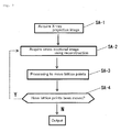
Fig. 2 is a flowchart showing the schematic procedure of a shape extraction method of the first embodiment of the present invention. -
Fig. 3 is an explanatory drawing for describing a projection image acquisition method of the first embodiment of the present invention. -
Fig. 4 is an explanatory drawing for explaining the shape extraction method of the first embodiment of the present invention. -
Fig. 5 is a flowchart for describing a procedure for moving lattice points, in the first embodiment of the present invention. -
Fig. 6 is an explanatory drawing for describing a procedure for moving lattice points, in the first embodiment of the present invention. -
Fig. 7 is an explanatory drawing for describing a procedure for moving lattice points, in the first embodiment of the present invention. -
Fig. 8 is an explanatory drawing for describing a procedure for moving lattice points, in the first embodiment of the present invention. -
Fig. 9 is an explanatory drawing for describing the advantages of the shape extraction method of the first embodiment of the present invention, withFig. 9(a) showing extraction results using the conventional method, andFig. 9(b) showing extraction results using the method of the embodiment. -
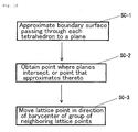
Fig. 10 is a flowchart for describing a procedure for moving lattice points, in a second embodiment of the present invention. -
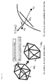
Fig. 11 is an explanatory drawing for describing boundary mesh deformation processing. -
Fig. 12 is an explanatory drawing for describing boundary mesh deformation processing. - A shape extraction system and a shape extraction device of a first embodiment of the present invention will be described in the following with reference to
Fig. 1 to Fig. 9 . - A shape extraction system of this embodiment is provided with a projective
image receiving section 1, a crosssection reconstruction section 2, a latticepoint movement section 3, and a surfaceshape output section 4. Each of these functional elements can basically be configured using computer programs. - The projective
image receiving section 1 receives image data of a projective image that has been acquired by radiation projection to an object. Here, the radiation is not only x-rays, but also includes a neutron beam and an electron beam. Also, the projection image is not only a transmission image, but also includes a reflected image. - The cross
section reconstruction section 2 uses a predetermined mesh structure to acquire cross-sectional images of the subject from image data of the projective image by reconstruction using tomography (known as CT). - The lattice
point movement section 3 is configured to carry out - (1) processing to move lattice points constituting the mesh in conformity with the surface shape of the object, based on cross-sectional images that have been acquired by reconstruction, and
- (2) processing to send a mesh that has had lattice point position corrected by the processing of (1) above to the cross
section reconstruction section 2, and acquiring an updated cross sectional image from the crosssection reconstruction section 2. - Detailed operation of the lattice
point movement section 3 will be described later. - The surface
shape output section 4 outputs the updated cross-sectional image to a suitable memory or to a subsequent process. - Next, a shape extraction method that uses the previously described system will be described in detail with reference to the flowchart of
Fig. 2 . In the following, description will be given using x-rays exemplifying the radiation. - First, an x-ray projection image (with this embodiment an x-ray transmission image) is obtained by a projection of irradiation to an object. A method of acquiring the x-ray projection image will be described with reference to
Fig. 3 . With this example, anobject 13 is placed between anx-ray source 11 and anx-ray detector 12. Thisobject 13 is mounted on a rotation table 14. If x-rays are projected to theobject 13 while theobject 13 is rotated by the rotation table 14, it is possible to acquire an x-ray projection image such as is shown inFig. 3 (b) from thex-ray detector 12. With the illustrated example, a so-called fan beam structure is shown where acquisition of one-dimensional projective images is repeated, but it is also possible to adopt a cone beam structure with which it is possible to acquire two-dimensional projective images simply by rotating the subject. As a method of acquiring x-ray projection images, it is possible to use a similar method to that in the related art, and so further detailed description will be omitted. - With the system of this embodiment, image data for a projection image that has been created as described above is received by the projective
image receiving section 1. - Next, a predetermined mesh structure is used to acquire cross-sectional images of the subject from image data of the projective images by reconstruction using tomography. This step will be further described with reference to
Fig. 4 . With the example ofFig. 4 , the object shown inFig. 4(a) is used. The obtained projection image (transmission image with the above example) is shown inFig. 4 (b) . Further, with this example, the triangular mesh structure shown inFig 4(c) is used as the predetermined mesh structure. On the premise of this mesh structure, it is possible to reconstruct a cross section image of the object using tomography. As a method for reconstructing cross-sectional images using tomography, it is possible to use a conventional method such as ML-EM (Maximum Likelihood - Expectation Maximization), and so detailed description will be omitted. Also, a cross-sectional image acquired through reconstruction is shown inFig. 4(c) . Here, portions shown in half tone (gray) are recognized as "blur". - Next, lattice points constituting the mesh structure are moved in conformity with the surface shape of the object, based on the cross-sectional image that has been acquired by reconstruction. A procedure for moving the lattice points will be described in detail with reference to
Fig. 5 . - First, a boundary line passing through each triangle constituting the mesh structure is approximated to a straight line. As will be understood, the position of the actual boundary line is unclear in this step, and so some sort of estimation is necessary. With this embodiment therefore, as described in the following, a method is used whereby first a normal of the boundary line is calculated, and secondly a position of a straight line is calculated. It is possible to reverse the order of these calculations.
- A normal of the estimated boundary line can be calculated using a gradient vector of the CT value.
- First, it is assumed that
a straight line approximation of a boundary of triangle T is a set of points x that satisfy the following equation.
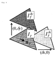
- Then, the entire mesh is subjected to translation by a microscopic amount in a positive direction of each axis (with this example the x-axis and the y-axis), and CT reconstruction is carried out. Here, the amount of movement in the x-axis direction is made δx, and the amount of movement in the y-axis direction is made δy.
- Next, a unit normal vector nT for the triangle T is calculated from the following equation (refer to
Fig. 6 ).
- IT : CT value with no translation
-

-

- In this way it is possible to obtain a normal to the estimated boundary line. Specifically, it is possible to determine orientation of the boundary line using this normal.
- The position of the boundary line can be estimated as follows.
- First, as described above,
a straight line approximation of a boundary surface of triangle T is a set of points x that satisfy the following equation.
- Then, point pT is placed on an edge, of the three edges of triangle T, where an orthogonal projection to a straight having a direction of vector nT becomes longest, and a ratio of surface areas of the triangle that has been divided by the straight line (specifically, an internal ratio) satisfies the following equation (refer to
Fig. 7 ).
-

-

- IT : CT value of triangle
- W: CT value (constant) of object
- B: CT value (constant) of air
- Using this condition, it is possible to estimate the position of a boundary line between the object and the air. If the position and orientation of the boundary line are known, it is possible to acquire a straight line that passes through the triangular region (namely the boundary line).
- Next, intersection points of the straight lines that have been acquired for each region, or points that approximate thereto, are obtained. Specifically, it is possible to carry out calculations as follows.
- Lattice point v is moved to a point x where E(x) below is minimum. Here, since the three or more straight lines generally do not cross at a single point, with this embodiment a point where a square sum of distance to the straight lines is the minimum is substituted for the single point (refer to the following equation).

N(v): set of triangles having lattice point ν as apex and CT value that is blurred - In this way it is possible to place a single lattice point on the estimated boundary line. By applying this operation to the triangular meshes that are blurred, it is possible to move each lattice point. If the moved lattice points are connected, it is possible to acquire the estimated boundary line.
- Next, lattice points that have been moved with the previously described procedure are further moved on the boundary line. Specifically, a barycentric position for lattice points surrounding the lattice point is first calculated. Then, the lattice point is moved to a position that is closest to the barycentric point, on the boundary line. In this way, there is the advantage that it is easy to carry out reconstruction using an ML-EL method.
- Next, it is determined whether or not the lattice point has actually moved in steps up to the aforementioned. In the case where the lattice point has moved, a moved lattice point is assumed and processing of the previous steps SA-2 to SA-4 is repeated. The result of carrying out lattice movement and repeating the reconstruction is shown in (d) to (f) of
Fig. 4 - In the case where the lattice point has not moved, a finally obtained cross-sectional image is output. The output destination can be set in accordance with the intended use of the data, but is, for example, a memory for data storage or a process for additional processing.
- With conventional CT reconstruction, calculation was performed using a square and regular lattice. Differing from this, with the procedure of the embodiment described above, the shape of the lattice is a convex polygon, and calculation for reconstruction is carried out using an irregular (unstructured) lattice (although it is also possible to use a regular lattice in an initial state). Further, with this embodiment, the shape of this lattice can be changed dynamically. These points constitute the feature of the above described procedure.
- Next, with reference to
Fig. 9 , a specific example using the above-described embodiment will be described by comparison with a conventional method. - With the conventional method (
Fig. 9(a) ), blurring is noticeable on the boundary line, as will also be understood from CT values of a cross-section in the direction of the arrows in the drawing. Conversely, with the example (Fig. 9(b) ), the boundary line is clear and there is little blurring. This effect is particularly striking at corner sections of the object. With the example ofFig. 9 , CT values of the object (subject) can be regarded as having three types. In this type of case also, in the case where preliminary CT values can be anticipated, it is possible to predict the boundary line by applying the previously described method to each boundary between two materials. - According to the method of this embodiment, therefore, there is the advantage that it is possible in an industrial situation, for example, to accurately acquire the shape of an component, being the object, in an industrial application.
- Next, a shape extraction method and shape extraction device of a second embodiment of the present invention will be described with reference to
Fig. 10 . In the description of this embodiment, elements that are basically common to the above-described first embodiment are assigned the same reference numerals, and cumbersome description will be avoided. - With the above-described first embodiment, it was possible to extract the surface shape of a subject by using a triangular mesh as a mesh structure. Differing from this, the second embodiment described in the following extracts a solid shape by using a tetrahedron mesh as the mesh structure. Also, with the first embodiment an ML - EL method was adopted as the CT reconstruction method. Differing from this, with the second embodiment an already known Feldkamp method (L. A. Feldkamp, L. C. Davis, and J. W. Kress. Practical conebeam algorithm. J. Opt. Soc. Am. a, 1:612 - 619, 1984.) is used. In this way it is possible, with the second embodiment, to obtain CT values f (c) at a barycenter c of each tetrahedron constituting the mesh. Here, a CT value f (c) at the barycenter of each tetrahedron can be treated as a CT value representing the element (the mesh).
- However, even in the case of extracting a solid shape, the device and method for extracting a solid shape are basically common to the above-described first embodiment. Specifically, each of the steps shown in
Fig. 2 are common to both embodiments, and the block diagram shown inFig. 1 is also common. It is essentially necessary, however, to make the following word replacements.
2D⇒3D
polygon⇒polyhedron
Triangle⇒tetrahedron
Straight line⇒planar surface
boundary line⇒boundary surface
surface area⇒volume - It is therefore necessary to slightly change the steps shown in SB-1 to SB-3 in
Fig. 5 . In the following, description of steps SC-1 to SC-3 corresponding to each step inFig. 5 is based onFig. 10 . Each step ofFig. 10 also, similarly to the case inFig. 5 , shows an example for shaping the step SA-3 ofFig. 2 . - First, processing to approximate a boundary surface passing through each tetrahedron constituting the mesh structure to a planar surface will be described.
- First, detection of a material boundary is carried out using CT values inherent to the material (already known). In the case where CT values for two types of material A and B are already known, a CT value Ft at a boundary surface between material A and material B is obtained as an average value of the CT values for A and B. With this example, since a component of a single material that has been placed in the atmosphere is assumed, material A is air and material B is the component. By comparing this value and the CT value of each tetrahedron, it is possible differentiate a tetrahedron included in material A and a tetrahedron included in material B. It is then possible to obtain a boundary mesh M as a set of triangles (triangles constituting surfaces of the tetrahedrons), commonly contained in tetrahedrons of material A and tetrahedrons of material B. Accordingly, an individual boundary mesh is a planar surface mesh of triangles. In this state, the boundary line surface usually passes through inner part of a tetrahedron mesh positioned on the boundary, but as will be understood, at what position of the mesh it passes is not known. Accordingly, at this point in time a boundary mesh M does not usually conform to the boundary surface of the subject body.
- Processing to approximate a position of the boundary mesh M to an ideal boundary surface by moving the position of the obtained boundary mesh M will be described in the following. As a prerequisite the optimum position of the boundary mesh M is considered to be as follows. Specifically, in order to be the optimum (namely corresponding to a boundary surface) boundary mesh M, the following are necessary:
- a barycenter mi of a triangle constituting the boundary mesh must be on the material boundary; and
- a normal of that triangle must be equivalent to a gradient direction of a CT value of that barycentric point (namely a direction in which CT value increases or decreases).
- How the barycentric position and normal direction of the detected boundary surface change at the correct material boundary is schematically shown in
Fig. 11(a) . However, "correct material boundary" here is not known at this point in time. In the description here, therefore, description is for "conditions that are supposed to be satisfied if an obtained boundary is correct". From now on, a barycentric position after movement will be represented by m'i. - A position m'i of a barycenter of a triangle constituting an optimum boundary mesh M is a point between barycenters ci and cj of two tetrahedrons including the boundary, where f(m'i) = Ft (refer to
Fig. 11(b) andFig. 12 ). - Ft is generally a number that a user can easily designate. For example, in the case where two things that touch at the boundary are air and an object, then since respective CT values are themselves generally known, it is possible to make between those two values Ft.
- Also, a normal to a triangle constituting the optimum boundary mesh is a vector n(m'i) for which a gradient ∇f(m'i) of a CT value for an obtained position m'i has been normalized. ∇f(m'i) can be obtained using central difference, as in the following equation.

- As a result of the above described processing, it is possible to acquire a boundary mesh M positioned on the material boundary surface. Specifically, it becomes possible to approximate the boundary surface to a planar surface.
- Apexes of adjacent meshes M are expected to align at both ends of edges constituting the boundary. However, with a boundary mesh that has been acquired as described above, the apexes do not generally align.
- QEM (quadric error metrics) is therefore used in order to cause the apexes of the boundary mesh M to move to an optimum position. Specifically, a position at which E(p), being a square of distance between each apex point p of the boundary mesh M and a planar surface of a boundary mesh that has been estimated as described above, becomes minimum, is obtained. E(p) is represented by the following formula.

- N (p) here represents a group of triangles that are adjacent to the apex p, while m'i and n(m'i) represent optimum barycentric position and normal of respective triangles ti.
- In the case of moving an apex using QEM, there may be cases in which a drawback arises where the mesh is reversed. In this type of case, it is preferable to carry out generating a new mesh (known as re-mesh). An already known re-mesh method can be used, and so detailed description will be omitted.
- Next, using E (p) obtained as described above, an extension point is moved such that that value becomes minimum. This step corresponds to step SB-3 in
Fig. 5 . - Subsequent processing is the same as that after SA-4 in
Fig. 2 in the description of the first embodiment, and so detailed description will be omitted. Also, the structure of the device and method of the second embodiment other than described above can be the same as for the first embodiment. - The present invention is not limited to the above-described embodiments, and various modifications can additionally be obtained within a scope that does not depart from the spirit of the invention.
- For example, each of the above-described structural elements can exist as a functional block, and can also exist as independent hardware. Also, as a method of implementation, it is possible to use hardware or to use computer software. Further, a single functional element of the present invention may be realized as a set of a plurality of functional elements, and a plurality of functional elements of the present invention may be implemented by a single functional element.
- It is also possible for each functional element constituting the present invention to exist separately. In the case of existing separately, necessary data can be exchanged by means of a network, for example. Similarly, it is also possible for each function of an internal part of each section to exist separately. For example, it is possible to implement each functional element, or some of the functional elements, of this embodiment using grid computing or cloud computing.
- Also, in the above-described first embodiment a mesh is constructed using triangles, but it is also possible to use different convex polygons instead of triangles.
-
- 1
- Projection image receiving section
- 2
- Cross-section Reconstruction section
- 3
- lattice point movement section
- 4
- Surface shape output section
- 11
- beam source
- 12
- Beam detector
- 13
- Object
- 14
- Rotating table
Claims (8)
- A shape extraction method comprising:(1) a step of receiving image data of a projective image that has been acquired by radiation projection to an object;(2) a step of using a predetermined mesh structure to acquire a cross-sectional image of the object from the image data of the projective image by reconstruction using tomography;(3) a step of causing a lattice point, that forms the mesh structure, to move in conformity with the surface shape of the obj ect, based on the cross-sectional image that has been acquired by the reconstruction; and(4) a step of carrying out step (2) using a mesh that has had position of the lattice point corrected using step (3), and then repeatedly executing step (3) and step (2) as many times as required.
- The shape extraction method of claim 1, wherein the processing for causing the lattice point to move in conformity with the surface shape of the object, in step (3), comprises:(3a) a step of approximating a boundary line between the object and portions outside of the object, the boundary line passing through a convex polygon that constitutes the mesh structure and that shares a specified lattice point, to a straight line for each convex polygon; and(3b) a step of moving the specified lattice point to an intersection point of the straight line for each convex polygon, or to a point approximated to that intersection point.
- The shape extraction method of claim 2, wherein the processing to approximate a boundary line between the object and portions outside of the object to a straight line for each convex polygon, in step (3a), comprises:(3a1) a step of obtaining a normal to the boundary line, based on a gradient vector of image data of the convex polygon; and(3a2) a step of obtaining a position of the boundary line such that a ratio of divided surface areas of the convex polygon, that has been divided by the boundary line, corresponds to a value of image data of the convex polygon.
- The shape extraction method of claim 1, wherein the mesh structure is a tetrahedron mesh for producing a three-dimensional shape.
- The shape extraction method of claim 4, wherein the processing for causing the lattice point to move in conformity with the surface shape of the object, in step (3), comprises:(3p) a step of obtaining barycentric positions for two adjacent tetrahedron meshes that also include a boundary surface;(3q) a step of obtaining a point constituting a predetermined CT value, between the barycentric positions of two tetrahedron meshes, as a barycenter of a triangle constituting a boundary mesh;(3r) a step of obtaining orientation of the boundary mesh such that a normal direction of a triangle constituting the boundary mesh conforms to a gradient direction of the CT values of the two adjacent tetrahedron meshes; and(3s) a step of moving the lattice point using an apex position of the triangle constituting the boundary mesh, that was obtained in steps 3q and 3r.
- A shape extraction system, comprising a projective image receiving section, a cross section reconstruction section, a lattice point movement section, and a surface shape output section, wherein
the projective image receiving section receives image data of a projective image that has been acquired by radiation projection to an object,
the cross section reconstruction section uses a predetermined mesh structure to acquire a cross-sectional image of the object from the image data of the projective image, by reconstruction using tomography,
the lattice point movement section is configured to carry out(1) processing to cause a lattice point, that forms the mesh, to move in conformity with the surface shape of the object, based on the cross-sectional image that has been acquired by the reconstruction, and2) processing to send a mesh that has had position of a lattice point corrected by the processing of (1) above to the cross section reconstruction section, and acquiring an updated cross sectional image from the cross section reconstruction section, andthe surface shape output section outputs the updated cross sectional image. - The shape extraction system of claim 6, wherein the mesh structure is a tetrahedron mesh for producing a three-dimensional shape.
- A computer program for executing the shape extraction method of any one of claim 1 to claim 5 using a computer.
Applications Claiming Priority (2)
| Application Number | Priority Date | Filing Date | Title |
|---|---|---|---|
| JP2011150024 | 2011-07-06 | ||
| PCT/JP2012/054889 WO2013005455A1 (en) | 2011-07-06 | 2012-02-28 | Shape extraction method and shape extraction system |
Publications (3)
| Publication Number | Publication Date |
|---|---|
| EP2731078A1 true EP2731078A1 (en) | 2014-05-14 |
| EP2731078A4 EP2731078A4 (en) | 2015-03-04 |
| EP2731078B1 EP2731078B1 (en) | 2017-12-13 |
Family
ID=47436816
Family Applications (1)
| Application Number | Title | Priority Date | Filing Date |
|---|---|---|---|
| EP12808211.2A Not-in-force EP2731078B1 (en) | 2011-07-06 | 2012-02-28 | Shape extraction method and shape extraction system |
Country Status (4)
| Country | Link |
|---|---|
| US (1) | US9336598B2 (en) |
| EP (1) | EP2731078B1 (en) |
| JP (1) | JP5888681B2 (en) |
| WO (1) | WO2013005455A1 (en) |
Families Citing this family (4)
| Publication number | Priority date | Publication date | Assignee | Title |
|---|---|---|---|---|
| JP6708117B2 (en) * | 2016-12-26 | 2020-06-10 | カシオ計算機株式会社 | Graphic drawing device, graphic drawing method, server device, program, and method for transmitting program |
| JP7216953B2 (en) * | 2018-11-30 | 2023-02-02 | 国立大学法人 東京大学 | Surface extraction method of CT volume in X-ray CT |
| CN110796693B (en) * | 2019-09-11 | 2023-03-21 | 重庆大学 | Method for directly generating two-dimensional finite element model from industrial CT slice image |
| CN116597100B (en) * | 2023-07-18 | 2023-10-20 | 杭州杰竞科技有限公司 | Automatic addressing method and system for 3D model exhibition hall |
Family Cites Families (10)
| Publication number | Priority date | Publication date | Assignee | Title |
|---|---|---|---|---|
| JPH0973558A (en) | 1995-09-07 | 1997-03-18 | Fujitsu Ltd | Polygon generator |
| JPH1125293A (en) | 1997-07-02 | 1999-01-29 | Hitachi Ltd | Mesh generation method |
| JP2002024855A (en) | 2000-07-12 | 2002-01-25 | Ricoh Co Ltd | Three-dimensional shape generation method and storage medium storing program for implementing the method |
| JP4061013B2 (en) | 2000-08-30 | 2008-03-12 | 株式会社リコー | 3D shape generation method, storage medium storing program for executing the method, and 3D shape generation apparatus |
| JP2003123057A (en) | 2001-10-15 | 2003-04-25 | Minolta Co Ltd | Method and apparatus for generating three-dimensional shape model |
| JP2005245830A (en) | 2004-03-05 | 2005-09-15 | Jgs:Kk | Tumor detection method, tumor detection apparatus and program |
| US7203267B2 (en) | 2004-06-30 | 2007-04-10 | General Electric Company | System and method for boundary estimation using CT metrology |
| JP4620565B2 (en) | 2005-10-06 | 2011-01-26 | 株式会社日立製作所 | Analysis mesh generator |
| CN101903911A (en) * | 2007-12-20 | 2010-12-01 | 皇家飞利浦电子股份有限公司 | 3D reconstruction of body and body contours |
| WO2009083864A2 (en) | 2007-12-20 | 2009-07-09 | Philips Intellectual Property & Standards Gmbh | Iterative reconstruction of polyhedral objects from few projections |
-
2012
- 2012-02-28 EP EP12808211.2A patent/EP2731078B1/en not_active Not-in-force
- 2012-02-28 WO PCT/JP2012/054889 patent/WO2013005455A1/en not_active Ceased
- 2012-02-28 JP JP2013522483A patent/JP5888681B2/en not_active Expired - Fee Related
- 2012-02-28 US US14/131,198 patent/US9336598B2/en not_active Expired - Fee Related
Also Published As
| Publication number | Publication date |
|---|---|
| WO2013005455A1 (en) | 2013-01-10 |
| JP5888681B2 (en) | 2016-03-22 |
| EP2731078A4 (en) | 2015-03-04 |
| US9336598B2 (en) | 2016-05-10 |
| JPWO2013005455A1 (en) | 2015-02-23 |
| US20140169651A1 (en) | 2014-06-19 |
| EP2731078B1 (en) | 2017-12-13 |
Similar Documents
| Publication | Publication Date | Title |
|---|---|---|
| EP3716214A1 (en) | Medical image processing apparatus and method for acquiring training images | |
| CN102711613B (en) | Computed tomography imaging method and system | |
| US11927586B2 (en) | Item inspection by radiation imaging using an iterative projection-matching approach | |
| US8724889B2 (en) | Method and apparatus for CT image reconstruction | |
| JP4920205B2 (en) | System and method for boundary estimation using CT measurements | |
| EP2547983B1 (en) | System and method for generating enhanced density distribution in three dimensional skeletal models | |
| Jia et al. | GPU-based fast low-dose cone beam CT reconstruction via total variation | |
| Huang et al. | Restoration of missing data in limited angle tomography based on Helgason–Ludwig consistency conditions | |
| Van Aarle et al. | Super-resolution for computed tomography based on discrete tomography | |
| Chan et al. | HIGH-ORDER TOTAL VARIATION REGULARIZATION APPROACH FOR AXIALLY SYMMETRIC OBJECT TOMOGRAPHY FROM A SINGLE RADIOGRAPH. | |
| US9466136B2 (en) | Methods and systems for performing model-based image processing | |
| EP2731078B1 (en) | Shape extraction method and shape extraction system | |
| US20200027254A1 (en) | Correction of sharp-edge artifacts in differential phase contrast ct images and its improvement in automatic material identification | |
| US9361712B2 (en) | CT image generation device and method and CT image generation system | |
| CN110268441A (en) | Method for obtaining 3D model data of multiple parts of an object | |
| Linde et al. | Trajectory optimization for few-view robot-based CT: Transitioning from static to object-specific acquisition geometries | |
| Karimi et al. | A hybrid stochastic-deterministic gradient descent algorithm for image reconstruction in cone-beam computed tomography | |
| Ito et al. | Orientation optimization and jig construction for xray ct scanning | |
| Miloevic | Fractal analysis of two dimensional images: parameters of the space-filling and shape | |
| JP5635732B2 (en) | Progressive convergence of multiple iteration algorithms | |
| Nguyen et al. | A low-cost and easy-to-use phantom for cone-beam geometry calibration of a tomographic X-ray system | |
| US12555294B2 (en) | Segmentation of computed tomography voxel data using machine learning | |
| Liu et al. | Cooperative data fusion of transmission and surface scan for improving limited-angle computed tomography reconstruction | |
| CN108780587A (en) | By correcting the lossless detection method carried out | |
| CN115359049B (en) | Finite angle CT image reconstruction method and device based on nonlinear diffusion model |
Legal Events
| Date | Code | Title | Description |
|---|---|---|---|
| PUAI | Public reference made under article 153(3) epc to a published international application that has entered the european phase |
Free format text: ORIGINAL CODE: 0009012 |
|
| 17P | Request for examination filed |
Effective date: 20140109 |
|
| AK | Designated contracting states |
Kind code of ref document: A1 Designated state(s): AL AT BE BG CH CY CZ DE DK EE ES FI FR GB GR HR HU IE IS IT LI LT LU LV MC MK MT NL NO PL PT RO RS SE SI SK SM TR |
|
| DAX | Request for extension of the european patent (deleted) | ||
| REG | Reference to a national code |
Ref country code: DE Ref legal event code: R079 Ref document number: 602012040926 Country of ref document: DE Free format text: PREVIOUS MAIN CLASS: G06T0015000000 Ipc: G01N0023040000 |
|
| A4 | Supplementary search report drawn up and despatched |
Effective date: 20150202 |
|
| RIC1 | Information provided on ipc code assigned before grant |
Ipc: G01N 23/04 20060101AFI20150127BHEP Ipc: G06T 11/00 20060101ALI20150127BHEP |
|
| 17Q | First examination report despatched |
Effective date: 20160729 |
|
| STAA | Information on the status of an ep patent application or granted ep patent |
Free format text: STATUS: EXAMINATION IS IN PROGRESS |
|
| GRAP | Despatch of communication of intention to grant a patent |
Free format text: ORIGINAL CODE: EPIDOSNIGR1 |
|
| STAA | Information on the status of an ep patent application or granted ep patent |
Free format text: STATUS: GRANT OF PATENT IS INTENDED |
|
| INTG | Intention to grant announced |
Effective date: 20170623 |
|
| GRAS | Grant fee paid |
Free format text: ORIGINAL CODE: EPIDOSNIGR3 |
|
| GRAA | (expected) grant |
Free format text: ORIGINAL CODE: 0009210 |
|
| STAA | Information on the status of an ep patent application or granted ep patent |
Free format text: STATUS: THE PATENT HAS BEEN GRANTED |
|
| AK | Designated contracting states |
Kind code of ref document: B1 Designated state(s): AL AT BE BG CH CY CZ DE DK EE ES FI FR GB GR HR HU IE IS IT LI LT LU LV MC MK MT NL NO PL PT RO RS SE SI SK SM TR |
|
| REG | Reference to a national code |
Ref country code: GB Ref legal event code: FG4D |
|
| REG | Reference to a national code |
Ref country code: AT Ref legal event code: REF Ref document number: 954869 Country of ref document: AT Kind code of ref document: T Effective date: 20171215 Ref country code: CH Ref legal event code: EP |
|
| REG | Reference to a national code |
Ref country code: IE Ref legal event code: FG4D |
|
| REG | Reference to a national code |
Ref country code: DE Ref legal event code: R096 Ref document number: 602012040926 Country of ref document: DE |
|
| REG | Reference to a national code |
Ref country code: NL Ref legal event code: MP Effective date: 20171213 |
|
| REG | Reference to a national code |
Ref country code: LT Ref legal event code: MG4D |
|
| PG25 | Lapsed in a contracting state [announced via postgrant information from national office to epo] |
Ref country code: FI Free format text: LAPSE BECAUSE OF FAILURE TO SUBMIT A TRANSLATION OF THE DESCRIPTION OR TO PAY THE FEE WITHIN THE PRESCRIBED TIME-LIMIT Effective date: 20171213 Ref country code: NO Free format text: LAPSE BECAUSE OF FAILURE TO SUBMIT A TRANSLATION OF THE DESCRIPTION OR TO PAY THE FEE WITHIN THE PRESCRIBED TIME-LIMIT Effective date: 20180313 Ref country code: LT Free format text: LAPSE BECAUSE OF FAILURE TO SUBMIT A TRANSLATION OF THE DESCRIPTION OR TO PAY THE FEE WITHIN THE PRESCRIBED TIME-LIMIT Effective date: 20171213 Ref country code: SE Free format text: LAPSE BECAUSE OF FAILURE TO SUBMIT A TRANSLATION OF THE DESCRIPTION OR TO PAY THE FEE WITHIN THE PRESCRIBED TIME-LIMIT Effective date: 20171213 |
|
| PGFP | Annual fee paid to national office [announced via postgrant information from national office to epo] |
Ref country code: DE Payment date: 20180219 Year of fee payment: 7 |
|
| REG | Reference to a national code |
Ref country code: AT Ref legal event code: MK05 Ref document number: 954869 Country of ref document: AT Kind code of ref document: T Effective date: 20171213 |
|
| PG25 | Lapsed in a contracting state [announced via postgrant information from national office to epo] |
Ref country code: LV Free format text: LAPSE BECAUSE OF FAILURE TO SUBMIT A TRANSLATION OF THE DESCRIPTION OR TO PAY THE FEE WITHIN THE PRESCRIBED TIME-LIMIT Effective date: 20171213 Ref country code: BG Free format text: LAPSE BECAUSE OF FAILURE TO SUBMIT A TRANSLATION OF THE DESCRIPTION OR TO PAY THE FEE WITHIN THE PRESCRIBED TIME-LIMIT Effective date: 20180313 Ref country code: HR Free format text: LAPSE BECAUSE OF FAILURE TO SUBMIT A TRANSLATION OF THE DESCRIPTION OR TO PAY THE FEE WITHIN THE PRESCRIBED TIME-LIMIT Effective date: 20171213 Ref country code: RS Free format text: LAPSE BECAUSE OF FAILURE TO SUBMIT A TRANSLATION OF THE DESCRIPTION OR TO PAY THE FEE WITHIN THE PRESCRIBED TIME-LIMIT Effective date: 20171213 Ref country code: GR Free format text: LAPSE BECAUSE OF FAILURE TO SUBMIT A TRANSLATION OF THE DESCRIPTION OR TO PAY THE FEE WITHIN THE PRESCRIBED TIME-LIMIT Effective date: 20180314 |
|
| PG25 | Lapsed in a contracting state [announced via postgrant information from national office to epo] |
Ref country code: NL Free format text: LAPSE BECAUSE OF FAILURE TO SUBMIT A TRANSLATION OF THE DESCRIPTION OR TO PAY THE FEE WITHIN THE PRESCRIBED TIME-LIMIT Effective date: 20171213 |
|
| PG25 | Lapsed in a contracting state [announced via postgrant information from national office to epo] |
Ref country code: ES Free format text: LAPSE BECAUSE OF FAILURE TO SUBMIT A TRANSLATION OF THE DESCRIPTION OR TO PAY THE FEE WITHIN THE PRESCRIBED TIME-LIMIT Effective date: 20171213 Ref country code: SK Free format text: LAPSE BECAUSE OF FAILURE TO SUBMIT A TRANSLATION OF THE DESCRIPTION OR TO PAY THE FEE WITHIN THE PRESCRIBED TIME-LIMIT Effective date: 20171213 Ref country code: CZ Free format text: LAPSE BECAUSE OF FAILURE TO SUBMIT A TRANSLATION OF THE DESCRIPTION OR TO PAY THE FEE WITHIN THE PRESCRIBED TIME-LIMIT Effective date: 20171213 Ref country code: EE Free format text: LAPSE BECAUSE OF FAILURE TO SUBMIT A TRANSLATION OF THE DESCRIPTION OR TO PAY THE FEE WITHIN THE PRESCRIBED TIME-LIMIT Effective date: 20171213 Ref country code: CY Free format text: LAPSE BECAUSE OF FAILURE TO SUBMIT A TRANSLATION OF THE DESCRIPTION OR TO PAY THE FEE WITHIN THE PRESCRIBED TIME-LIMIT Effective date: 20171213 |
|
| PG25 | Lapsed in a contracting state [announced via postgrant information from national office to epo] |
Ref country code: PL Free format text: LAPSE BECAUSE OF FAILURE TO SUBMIT A TRANSLATION OF THE DESCRIPTION OR TO PAY THE FEE WITHIN THE PRESCRIBED TIME-LIMIT Effective date: 20171213 Ref country code: SM Free format text: LAPSE BECAUSE OF FAILURE TO SUBMIT A TRANSLATION OF THE DESCRIPTION OR TO PAY THE FEE WITHIN THE PRESCRIBED TIME-LIMIT Effective date: 20171213 Ref country code: IS Free format text: LAPSE BECAUSE OF FAILURE TO SUBMIT A TRANSLATION OF THE DESCRIPTION OR TO PAY THE FEE WITHIN THE PRESCRIBED TIME-LIMIT Effective date: 20180413 Ref country code: AT Free format text: LAPSE BECAUSE OF FAILURE TO SUBMIT A TRANSLATION OF THE DESCRIPTION OR TO PAY THE FEE WITHIN THE PRESCRIBED TIME-LIMIT Effective date: 20171213 Ref country code: IT Free format text: LAPSE BECAUSE OF FAILURE TO SUBMIT A TRANSLATION OF THE DESCRIPTION OR TO PAY THE FEE WITHIN THE PRESCRIBED TIME-LIMIT Effective date: 20171213 Ref country code: RO Free format text: LAPSE BECAUSE OF FAILURE TO SUBMIT A TRANSLATION OF THE DESCRIPTION OR TO PAY THE FEE WITHIN THE PRESCRIBED TIME-LIMIT Effective date: 20171213 |
|
| REG | Reference to a national code |
Ref country code: CH Ref legal event code: PL Ref country code: DE Ref legal event code: R097 Ref document number: 602012040926 Country of ref document: DE |
|
| PG25 | Lapsed in a contracting state [announced via postgrant information from national office to epo] |
Ref country code: MC Free format text: LAPSE BECAUSE OF FAILURE TO SUBMIT A TRANSLATION OF THE DESCRIPTION OR TO PAY THE FEE WITHIN THE PRESCRIBED TIME-LIMIT Effective date: 20171213 |
|
| PLBE | No opposition filed within time limit |
Free format text: ORIGINAL CODE: 0009261 |
|
| STAA | Information on the status of an ep patent application or granted ep patent |
Free format text: STATUS: NO OPPOSITION FILED WITHIN TIME LIMIT |
|
| 26N | No opposition filed |
Effective date: 20180914 |
|
| GBPC | Gb: european patent ceased through non-payment of renewal fee |
Effective date: 20180313 |
|
| REG | Reference to a national code |
Ref country code: IE Ref legal event code: MM4A |
|
| REG | Reference to a national code |
Ref country code: BE Ref legal event code: MM Effective date: 20180228 |
|
| PG25 | Lapsed in a contracting state [announced via postgrant information from national office to epo] |
Ref country code: LU Free format text: LAPSE BECAUSE OF NON-PAYMENT OF DUE FEES Effective date: 20180228 Ref country code: LI Free format text: LAPSE BECAUSE OF NON-PAYMENT OF DUE FEES Effective date: 20180228 Ref country code: CH Free format text: LAPSE BECAUSE OF NON-PAYMENT OF DUE FEES Effective date: 20180228 Ref country code: DK Free format text: LAPSE BECAUSE OF FAILURE TO SUBMIT A TRANSLATION OF THE DESCRIPTION OR TO PAY THE FEE WITHIN THE PRESCRIBED TIME-LIMIT Effective date: 20171213 |
|
| REG | Reference to a national code |
Ref country code: FR Ref legal event code: ST Effective date: 20181031 |
|
| PG25 | Lapsed in a contracting state [announced via postgrant information from national office to epo] |
Ref country code: IE Free format text: LAPSE BECAUSE OF NON-PAYMENT OF DUE FEES Effective date: 20180228 |
|
| PG25 | Lapsed in a contracting state [announced via postgrant information from national office to epo] |
Ref country code: FR Free format text: LAPSE BECAUSE OF NON-PAYMENT OF DUE FEES Effective date: 20180228 Ref country code: BE Free format text: LAPSE BECAUSE OF NON-PAYMENT OF DUE FEES Effective date: 20180228 Ref country code: GB Free format text: LAPSE BECAUSE OF NON-PAYMENT OF DUE FEES Effective date: 20180313 Ref country code: SI Free format text: LAPSE BECAUSE OF FAILURE TO SUBMIT A TRANSLATION OF THE DESCRIPTION OR TO PAY THE FEE WITHIN THE PRESCRIBED TIME-LIMIT Effective date: 20171213 |
|
| REG | Reference to a national code |
Ref country code: DE Ref legal event code: R119 Ref document number: 602012040926 Country of ref document: DE |
|
| PG25 | Lapsed in a contracting state [announced via postgrant information from national office to epo] |
Ref country code: DE Free format text: LAPSE BECAUSE OF NON-PAYMENT OF DUE FEES Effective date: 20190903 Ref country code: MT Free format text: LAPSE BECAUSE OF NON-PAYMENT OF DUE FEES Effective date: 20180228 |
|
| PG25 | Lapsed in a contracting state [announced via postgrant information from national office to epo] |
Ref country code: TR Free format text: LAPSE BECAUSE OF FAILURE TO SUBMIT A TRANSLATION OF THE DESCRIPTION OR TO PAY THE FEE WITHIN THE PRESCRIBED TIME-LIMIT Effective date: 20171213 |
|
| PG25 | Lapsed in a contracting state [announced via postgrant information from national office to epo] |
Ref country code: PT Free format text: LAPSE BECAUSE OF FAILURE TO SUBMIT A TRANSLATION OF THE DESCRIPTION OR TO PAY THE FEE WITHIN THE PRESCRIBED TIME-LIMIT Effective date: 20171213 Ref country code: HU Free format text: LAPSE BECAUSE OF FAILURE TO SUBMIT A TRANSLATION OF THE DESCRIPTION OR TO PAY THE FEE WITHIN THE PRESCRIBED TIME-LIMIT; INVALID AB INITIO Effective date: 20120228 |
|
| PG25 | Lapsed in a contracting state [announced via postgrant information from national office to epo] |
Ref country code: MK Free format text: LAPSE BECAUSE OF NON-PAYMENT OF DUE FEES Effective date: 20171213 |
|
| PG25 | Lapsed in a contracting state [announced via postgrant information from national office to epo] |
Ref country code: AL Free format text: LAPSE BECAUSE OF FAILURE TO SUBMIT A TRANSLATION OF THE DESCRIPTION OR TO PAY THE FEE WITHIN THE PRESCRIBED TIME-LIMIT Effective date: 20171213 |