EP2731075A1 - Backfilling points in a point cloud - Google Patents
Backfilling points in a point cloud Download PDFInfo
- Publication number
- EP2731075A1 EP2731075A1 EP13190777.6A EP13190777A EP2731075A1 EP 2731075 A1 EP2731075 A1 EP 2731075A1 EP 13190777 A EP13190777 A EP 13190777A EP 2731075 A1 EP2731075 A1 EP 2731075A1
- Authority
- EP
- European Patent Office
- Prior art keywords
- point cloud
- points
- new
- data array
- image
- Prior art date
- Legal status (The legal status is an assumption and is not a legal conclusion. Google has not performed a legal analysis and makes no representation as to the accuracy of the status listed.)
- Granted
Links
Images






Classifications
-
- G—PHYSICS
- G06—COMPUTING OR CALCULATING; COUNTING
- G06T—IMAGE DATA PROCESSING OR GENERATION, IN GENERAL
- G06T15/00—Three-dimensional [3D] image rendering
- G06T15/04—Texture mapping
-
- G—PHYSICS
- G06—COMPUTING OR CALCULATING; COUNTING
- G06T—IMAGE DATA PROCESSING OR GENERATION, IN GENERAL
- G06T3/00—Geometric image transformations in the plane of the image
- G06T3/40—Scaling of whole images or parts thereof, e.g. expanding or contracting
- G06T3/4007—Scaling of whole images or parts thereof, e.g. expanding or contracting based on interpolation, e.g. bilinear interpolation
-
- G—PHYSICS
- G06—COMPUTING OR CALCULATING; COUNTING
- G06T—IMAGE DATA PROCESSING OR GENERATION, IN GENERAL
- G06T1/00—General purpose image data processing
-
- G—PHYSICS
- G06—COMPUTING OR CALCULATING; COUNTING
- G06T—IMAGE DATA PROCESSING OR GENERATION, IN GENERAL
- G06T17/00—Three-dimensional [3D] modelling for computer graphics
-
- G—PHYSICS
- G06—COMPUTING OR CALCULATING; COUNTING
- G06T—IMAGE DATA PROCESSING OR GENERATION, IN GENERAL
- G06T3/00—Geometric image transformations in the plane of the image
- G06T3/40—Scaling of whole images or parts thereof, e.g. expanding or contracting
- G06T3/4038—Image mosaicing, e.g. composing plane images from plane sub-images
-
- G—PHYSICS
- G06—COMPUTING OR CALCULATING; COUNTING
- G06T—IMAGE DATA PROCESSING OR GENERATION, IN GENERAL
- G06T5/00—Image enhancement or restoration
- G06T5/70—Denoising; Smoothing
-
- H—ELECTRICITY
- H04—ELECTRIC COMMUNICATION TECHNIQUE
- H04N—PICTORIAL COMMUNICATION, e.g. TELEVISION
- H04N13/00—Stereoscopic video systems; Multi-view video systems; Details thereof
- H04N13/10—Processing, recording or transmission of stereoscopic or multi-view image signals
- H04N13/106—Processing image signals
- H04N13/128—Adjusting depth or disparity
-
- H—ELECTRICITY
- H04—ELECTRIC COMMUNICATION TECHNIQUE
- H04N—PICTORIAL COMMUNICATION, e.g. TELEVISION
- H04N13/00—Stereoscopic video systems; Multi-view video systems; Details thereof
- H04N13/20—Image signal generators
- H04N13/204—Image signal generators using stereoscopic image cameras
- H04N13/25—Image signal generators using stereoscopic image cameras using two or more image sensors with different characteristics other than in their location or field of view, e.g. having different resolutions or colour pickup characteristics; using image signals from one sensor to control the characteristics of another sensor
-
- G—PHYSICS
- G06—COMPUTING OR CALCULATING; COUNTING
- G06T—IMAGE DATA PROCESSING OR GENERATION, IN GENERAL
- G06T2210/00—Indexing scheme for image generation or computer graphics
- G06T2210/56—Particle system, point based geometry or rendering
Definitions
- the present disclosure relates generally to point clouds and, in particular, to increasing the resolution of point clouds. Still more particularly, the present disclosure relates to a system and method for increasing the number of points in a point cloud to increase the resolution of the point cloud.
- a point cloud is a collection of points in a three-dimensional (3D) coordinate system that describe a three-dimensional scene.
- the points in a point cloud represent external surfaces of objects.
- a light detection and ranging (LIDAR) system is an example of one type of sensor system capable of generating a point cloud.
- Point clouds may also be generated using, for example, stereo camera systems, mobile laser imaging systems, and other types of sensor systems.
- Point clouds may be used for performing various operations such as, for example, object identification, object classification, scene visualization, segmentation, two-dimensional image data enhancement, and/or other types of operations.
- the level of performance with which these operations are performed using a point cloud may depend on the resolution of that point cloud.
- the "resolution" of a point cloud may be the level of detail with which features in the scene captured by the point cloud may be discernible within the point cloud.
- the resolution of a point cloud may depend on the number of points in the point cloud and/or the point density of the points in one or more portions of the point cloud.
- point density is a measure of the number of points per unit volume. A portion of a point cloud having a higher density than another portion of the point cloud may be less sparse than the other portion.
- object identification, object classification, segmentation, and/or visualization of a scene using a sparse point cloud may yield inaccurate results.
- a point cloud may be insufficiently dense to correctly identify or classify an object.
- Some currently available solutions for increasing the number of points in a point cloud include making assumptions about the objects in the scene. For example, assumptions may be made about the shape of an object in the scene and new points may be added to the point cloud based on those assumptions. However, with these types of solutions, the locations in the three-dimensional reference coordinate system at which the new points are added may be less accurate than desired.
- some currently available solutions may be unable to account for actual holes or gaps in a scene. For example, with some currently available solutions, new points may be added to a point cloud at locations that represent actual holes or gaps in the scene. Still further, some currently available solutions may add points to a point cloud that connect objects that are unconnected in the scene, such as, for example, a tree top and the ground. Therefore, it would be desirable to have a method and apparatus that takes into account at least some of the issues discussed above, as well as other possible issues.
- an apparatus comprises an image processing system.
- the image processing system is configured to map at least a portion of points in a point cloud of a scene to a two-dimensional image of the scene to form transformed points.
- the image processing system is configured to create a fused data array using the two-dimensional image and the transformed points. Further, the image processing system is configured to identify new points for the point cloud using the fused data array and add the new points to the point cloud to form a new point cloud.
- an image processing system comprises a fusion manager, a depth value generator, and a point cloud manager.
- the fusion manager is configured to map at least a portion of points in a point cloud of a scene to a two-dimensional image of the scene to form transformed points and configured to create a fused data array using the two-dimensional image and the transformed points.
- the fused data array includes matched elements associated with filled data vectors comprising non-null depth values and unmatched elements associated with unfilled data vectors comprising null depth values.
- the depth value generator is configured to identify new depth values to replace at least a portion of the null depth values.
- the point cloud manager is configured to identify new points for the point cloud using the new depth values and add the new points to the point cloud to form a new point cloud.
- a computer-implemented method for increasing a number of points in a point cloud is provided.
- a two-dimensional image of a scene and the point cloud of the scene are received. At least a portion of the points in the point cloud are mapped to the two-dimensional image to form transformed points.
- a fused data array is created using the two-dimensional image and the transformed points. New points for the point cloud are identified using the fused data array. The new points are added to the point cloud to form a new point cloud.
- the different illustrative embodiments recognize and take into account different considerations. For example, the illustrative embodiments recognize and take into account that it may be desirable to have a method for increasing the number of points in a point cloud by adding new points to locations in the three-dimensional reference coordinate system for the point cloud that have a desired level of accuracy.
- the illustrative embodiments recognize and take into account that a two-dimensional image of the same scene captured by a point cloud may be used to increase the number of points in a point cloud.
- the illustrative embodiments recognize and take into account that it may be desirable to process the two-dimensional image to increase the number of points in the point cloud without making assumptions about the scene and/or the shapes of objects in the scene captured in the two-dimensional image.
- the illustrative embodiments provide a system and method for increasing the number of points in a point cloud of a scene using a two-dimensional image of the scene. Further, this system and method may increase the number of points in the point cloud without making any assumptions about the scene.
- image processing environment 100 is an example of an environment in which image processing system 102 may be used to process images and point clouds.
- image processing system 102 may be implemented in computer system 104.
- Computer system 104 may be comprised of one or more computers and/or other types of hardware. When more than one computer is present in computer system 104, these computers may be in communication with one another.
- Image processing system 102 may be configured to receive data from first sensor system 106 and second sensor system 108.
- First sensor system 106 and second sensor system 108 are configured to generate data about scene 110.
- Scene 110 may include features 111.
- Features 111 may include, for example, without limitation, objects 112.
- Objects 112 may include, for example, without limitation, any number of vehicles, buildings, manmade structures, people, animals, landscape features, and/or other types of objects. Further, features 111 may also include, for example, a background of scene 110.
- first sensor system 106 may take the form of first imaging system 114.
- First imaging system 114 may be any system configured to generate imaging data 116 for scene 110.
- first imaging system 114 takes the form of camera system 118.
- camera system 118 may take the form of an electro-optical camera system.
- Imaging data 116 may include, for example, without limitation, image 120.
- image 120 may be two-dimensional image 121.
- image 120 When generated by an electro-optical camera system, image 120 may be referred to as an electro-optical image.
- image 120 may be comprised of pixels 122.
- Pixels 122 may be arranged in a two-dimensional array comprised of rows and columns.
- pixel locations 124 may identify the locations of pixels 122 within this array.
- each of pixel locations 124 may identify a row and column for a corresponding pixel.
- each of pixels 122 may be associated with pixel data.
- the pixel data for a pixel may include, for example, without limitation, a number of color values, an intensity value, and/or other values.
- the number of color values may include, for example, a red value, a green value, and a blue value based on the RGB color model.
- second sensor system 108 may take the form of second imaging system 126.
- Second imaging system 126 may be any system configured to generate point data 128 for scene 110.
- second imaging system 126 takes the form of light detection and ranging system 130.
- Point data 128 may include point cloud 132.
- Point cloud 132 may take the form of three-dimensional point cloud 133 in these illustrative examples.
- Point cloud 132 of scene 110 may be generated from a different perspective than image 120 of scene 110 in some illustrative examples.
- Point cloud 132 is comprised of points 134 in a three-dimensional reference coordinate system.
- each of point locations 136 may identify the coordinates for a corresponding point in this three-dimensional reference coordinate system.
- the reference coordinate system may be a real world coordinate system such as, for example, a geographical coordinate system.
- Resolution 140 of point cloud 132 may be an identification of the level of detail with which features 111 in scene 110 captured by point cloud 132 may be discernible within point cloud 132. In some cases, resolution 140 of point cloud 132 may depend on number 138 of points 134 in point cloud 132. For example, as number 138 of points 134 in point cloud 132 increases, resolution 140 of point cloud 132 may also increase.
- Image processing system 102 is configured to receive image 120 generated by camera system 118 and point cloud 132 generated by light detection and ranging system 130. Image processing system 102 uses image 120 to increase number 138 of point cloud 132, and thereby resolution 140 of point cloud 132. More specifically, image processing system 102 may be configured to generate new points that may be added to point cloud 132.
- image processing system 102 may include fusion manager 142, depth value generator 144, and point cloud manager 145.
- Fusion manager 142 is configured to map at least a portion of points 134 in point cloud 132 to image 120 to form transformed points 146. More specifically, fusion manager 142 is configured to map the point locations for at least a portion of points 134 in point cloud 132 to pixel locations in the image plane of image 120.
- the image plane of image 120 may be the plane that lies within the two-dimensional array of pixels 122.
- Transformed points 146 may be formed using, for example, transformation algorithm 148.
- Transformation algorithm 148 may include any number of processes, equations, and/or algorithms for mapping at least a portion of points 134 to pixel locations in the image plane of image 120.
- transformation algorithm 148 may include a camera pose estimation algorithm such as, for example, an efficient perspective-n-point (EPnP) camera pose estimation algorithm.
- EPnP efficient perspective-n-point
- the camera pose estimation algorithm may provide pose information for a pose of camera system 118.
- the pose of camera system 118 may be comprised of at least one of an orientation and position of camera system 118.
- Fusion manager 142 uses transformation algorithm 148 to transform the three-dimensional reference coordinate system for point cloud 132 into a three-dimensional camera-centric coordinate system.
- fusion manager 142 may use the pose information for camera system 118 provided by the camera post estimation algorithm to transform the three-dimensional reference coordinate system into the three-dimensional camera-centric coordinate system.
- the origin of the three-dimensional reference coordinate system may be moved to the location of camera system 118.
- Fusion manager 142 then identifies camera-centric coordinates for points 134 in the three-dimensional camera-centric coordinate system.
- fusion manager 142 is configured to map the camera-centric coordinates for points 134 to corresponding pixel locations in the image plane of image 120 to form transformed points 146.
- the camera-centric coordinates for a point in point cloud 132 may be mapped to a pixel location that lies inside image 120 or outside of image 120 but in the same image plane as image 120.
- Transformed points 146 may include only those points that are mapped to pixel locations within image 120.
- Fusion manager 142 is configured to create fused data array 150 using image 120 and transformed points 146.
- Fused data array 150 includes data that has been fused together based on image 120 and point cloud 132.
- fused data array 150 may include elements 152. Each of elements 152 may correspond to one of pixels 122 in image 120, and each of pixels 122 may correspond to one of elements 152. In particular, elements 152 may have a one-to-one correspondence with pixels 122 in image 120. In this manner, fused data array 150 may have a same size as the array of pixels 122 in image 120.
- each of transformed points 146 corresponds to a pixel in image 120
- each of transformed points 146 may also correspond to the element in fused data array 150 that corresponds to that pixel.
- Each of transformed points 146 may be described as mapping to a corresponding one of elements 152.
- transformed points 146 may map to a first portion of elements 152.
- This first portion of elements may be referred to as matched elements.
- a second portion of elements 152 may not have any transformed points that map to these elements.
- the second portion of elements 152 may be referred to as unmatched elements.
- each of elements 152 may be associated with a data vector, such as, for example, data vector 154.
- data vector 154 may include depth value 156.
- Depth value 156 may be a distance between the transformed point corresponding to the element associated with data vector 154 and camera system 118 within the three-dimensional camera-centric coordinate system.
- depth value 156 When the element associated with data vector 154 is an unmatched element, depth value 156 may be a null or zero value. When the element associated with data vector 154 is a matched element, depth value 156 may be a non-null or non-zero value. Data vector 154 may be referred to as an unfilled data vector when depth value 156 is a null or zero value and a filled data vector when depth value 156 is a non-null or non-zero value. In this manner, unmatched elements in fused data array 150 may be associated with unfilled data vectors and matched elements in fused data array 150 may be associated with filled data vectors.
- data vector 154 may also include other data such as, for example, pixel location 157, original pixel data 159, and/or other types of data.
- Pixel location 157 may be the pixel location for the pixel corresponding to the element associated with data vector 154.
- Original pixel data 159 may be the pixel data in image 120 for the pixel corresponding to the element associated with data vector 154.
- depth value generator 144 is configured to generate new depth values 158 for at least a portion of the unfilled data vectors associated with unmatched elements in fused data array 150. In this manner, depth value generator 144 may identify new depth values 158 to replace at least a portion of the null depth values. The unfilled data vectors may then be filled, by fusion manager 142, with new depth values 158 to form modified fused data array 160.
- New depth values 158 may be generated using modified fused data array 160.
- depth value generator 144 may use windows of selected sizes to scan and process fused data array 150.
- estimation techniques such as linear estimation techniques, may be used to generate new depth values 158. An example of one implementation for the process of generating new depth values 158 is described in Figures 2-6 below.
- Point cloud manager 145 is configured to use modified fused data array 160 to create new point cloud 162.
- point cloud manager 145 may use the portion of elements in fused data array 150 having data vectors filled with new depth values 158 to identify new points 164 for point cloud 132.
- point cloud manager 145 may map each of the pixel locations for the pixels corresponding to the portion of elements in fused data array 150 having data vectors filled with new depth values 158 to camera-centric coordinates in the three-dimensional camera-centric coordinate system. These camera-centric coordinates may then be transformed into the three-dimensional reference coordinate system for the original point cloud, point cloud 132, to form new points 164. This transformation may be performed using, for example, without limitation, inverse transformation algorithm 166. Inverse transformation algorithm 166 may be the inverse of transformation algorithm 148 used by fusion manager 142.
- Point cloud manager 145 adds new points 164 to point cloud 132 to form new point cloud 162. This process of adding new points 164 to point cloud 132 may be referred to as "backfilling" point cloud 132.
- New point cloud 162 may have a greater number of points than number 138 of points 134 in point cloud 132.
- New points 164 may provide new point cloud 162 with an increased resolution as compare to resolution 140 of point cloud 132.
- New point 164 may capture features 111 in scene 110 with a desired level of accuracy.
- new point cloud 162 may be used in the place of point cloud 132 for performing any number of operations.
- new points 164 may enhance the visualization of scene 110 in new point cloud 162 as compared to point cloud 132. Further, new points 164 may allow one or more of objects 112 in scene 110 to be identified and/or classified using new point cloud 162 with a higher level of accuracy as compared to using point cloud 132.
- initial fused image 168 may be generated by fusion manager 142 using image 120 and point cloud 132. At least a portion of the points in point cloud 132 may be mapped to pixel locations in image 120 and overlaid on image 120 to create initial fused image 168.
- Final fused image 170 may be generated by fusion manager 142 using image 120 and new point cloud 162. At least a portion of the points in new point cloud 162 may be mapped to pixel locations in image 120 and overlaid on image 120 to create final fused image 170.
- the visualization of scene 110 in final fused image 170 may be enhanced as compared to the visualization of scene 110 in initial fused image 168.
- the greater number of points in final fused image 170 as compared to initial fused image 168 may enhance the visualization of scene 110 in final fused image 170.
- image processing environment 100 in Figure 1 is not meant to imply physical or architectural limitations to the manner in which an illustrative embodiment may be implemented.
- Other components in addition to or in place of the ones illustrated may be used. Some components may be optional.
- the blocks are presented to illustrate some functional components. One or more of these blocks may be combined, divided, or combined and divided into different blocks when implemented in an illustrative embodiment.
- depth value generator 144 may be considered part of fusion manager 142. In other illustrative examples, fusion manager 142 and/or depth value generator 144 may be considered part of point cloud manager 145.
- some other module in image processing system 102 may be used to form initial fused image 168 and/or final fused image 170.
- some other data processing system or processor unit may be configured to process image 120 and new point cloud 162 to form final fused image 170.
- FIGS 2-6 illustrations of a process for generating new depth values for unfilled data vectors associated with unmatched elements in a fused data array are depicted in accordance with an illustrative embodiment.
- the process illustrated in Figures 2-6 may be an example of one manner in which new depth values 158 in Figure 1 may be generated. Further, this process may be performed using, for example, depth value generator 144 in Figure 1 .
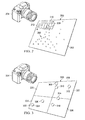
- fused data array 200 may be an example of one implementation for fused data array 150 in Figure 1 .
- fused data array 200 may be the fusion of image 202 and transformed points 206.
- Image 202 may be an image generated by, for example, camera system 204.
- Transformed points 206 may include a portion of the points in a point cloud mapped to pixel locations in image 202, and thereby, elements in fused data array 200.
- Fused data array 200 may have been generated by, for example, fusion manager 142 in Figure 1 .
- depth value generator 144 may move window 208 along fused data array 200 in the direction of arrow 210 and arrow 212 to process fused data array 200.
- window 208 may be moved to the location of every element within fused data array 200.
- window 208 may have one of a group of selected sizes.
- a "group of" items may include one or more items. In this manner, a group of selected sizes may include one or more selected sizes.
- Fused data array 200 may be fully scanned and processed using a window having each size in the group of selected sizes.
- Moving window 208 to the location of an element in fused data array 200 means centering window 208 at that element in this illustrative example.
- the portion of fused data array 200 overlapped by window 208 may be processed by depth value generator 144 to identify a new depth value for the unfilled data vector associated with this unmatched element.
- FIG. 3 an illustration of a portion of fused data array 200 overlapped by window 208 from Figure 2 is depicted in accordance with an illustrative embodiment.
- portion 300 of fused data array 200 from Figure 2 is overlapped by window 208.
- group of matched elements 302 identify the elements in portion 300 of fused data array 200 to which a portion of transformed points 206 in Figure 2 have been mapped. All other elements (not shown in this view) in portion 300 of fused data array 200 may be unmatched elements to which transformed points have not been mapped. As depicted, group of matched elements 302 includes matched elements 304, 306, 308, 310, 312, 314, and 316.
- Depth value generator 144 first confirms that the depth value in the data vector associated with the element at which window 208 is centered is a null depth value. If the depth value is a non-null depth value, depth value generator 144 moves window 208 to another location. If the depth value is a null depth value, depth value generator 144 continues processing portion 300 of fused data array 200.
- portion 300 of fused data array 200 is depicted divided into quadrants 320, 322, 324, and 326.
- Depth value generator 144 is configured to confirm that a sufficient number of matched elements are present in portion 300 of fused data array 200. Further, depth value generator 144 is configured to confirm that at least one matched element is present in each of quadrants 320, 322, 324, and 326.
- depth value generator 144 may continue processing portion 300 of fused data array 200.
- depth value generator 144 may move window 208 to a next location along fused data array 200.
- depth value generator 144 is configured to generate a score for each matched element in group of matched elements 302.
- the score for a matched element may be based on the depth value in the filled data vector associated with the matched element and a similarity of the matched element to the other matched elements in group of matched elements 302.
- the depth value in the filled data vector associated with the matched element may be the distance between camera system 204 and the location of the transformed point, which has been mapped to the matched element, within the three-dimensional camera-centric coordinate system.
- the depth values for group of matched elements 302 may be distances 402, 404, 406, 408, 410, 412, and 414 between matched elements 304, 306, 308, 310, 312, 314, and 316, respectively, and camera system 204.
- the similarity of the matched element to the other matched elements in group of matched elements 302 may be based on any number of features. These features may include, for example, without limitation, pixel location, color, intensity, and/or other types of features or data within a data vector. In this illustrative example, the similarity of the matched element to the other matched elements may be based on the distance between the pixel location identified in the data vector associated with the matched element and ideal pixel location 400. The pixel location may be the same as the location for the matched element within fused data array 200.
- the scores generated for group of matched elements 302, as described in Figure 4 may be sorted, or ordered.
- the desired number of support elements may be five support elements in this illustrative example.
- the five matched elements having the five lowest scores are selected as support elements 500.
- Support elements 500 include matched elements 306, 308, 310, 312, and 314.
- support elements 500 may be selected such that the number of new points created for actual holes and/or gaps in the scene captured by image 202 is reduced. Further, support elements 500 may be selected such that the new points created actually represent an external surface of an object.
- FIG. 6 an illustration of the generation of a new depth value is depicted in accordance with an illustrative embodiment.
- support elements 500 from Figure 5 may be used to generate a new depth value for element 600 at which window 208 was centered.
- Element 600 is at location 602 in fused data array 200, which may be the center location of portion 300 of fused data array 200.
- the new depth value for element 600 may be generated using, for example, linear estimation.
- a linear estimation algorithm may use the depth value in the filled data vector associated with each of support elements 500 to estimate the new depth value for element 600. This new depth value may be used to fill the data vector associated with element 600.
- the entire fused data array 200 may be scanned and processed with a window having each of a group of selected sizes. Still further, this entire process of using the windows having the group of selected sizes may be iterated any number of times to fill at least a portion of the unfilled data vectors associated with the unmatched elements in fused data array 200.
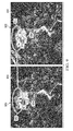
- Fused image 700 may be an example of one implementation for fused data array 150 in Figure 1 .
- Fused image 700 may be a combination of image 702 and transformed points 704.
- each pixel in fused image 700 may be associated with a data vector, such as data vector 154 in Figure 1 .
- initial fused image 800 is an example of one implementation for initial fused image 168 in Figure 1 .
- final fused image 802 is an example of one implementation for final fused image 170 in Figure 1 .
- initial fused image 800 is a fusion of image 804 and transformed points 806.
- Transformed points 806 may include points mapped from an original point cloud, such as, for example, point cloud 132 in Figure 1 .
- Final fused image 802 is a fusion of the same image 804 and transformed points 808.
- Transformed points 808 may include points mapped from a new point cloud, such as, for example, new point cloud 162 in Figure 1 .
- the scene captured in image 804 may be better realized by transformed points 808 in final fused image 802 as compared to transformed points 806 in initial fused image 800.
- FIG. 9 an illustration of a comparison of a final fused image generated when support elements are used and a final fused image generated when support elements are not used is depicted in accordance with an illustrative embodiment.
- a comparison of final fused image 900 and final fused image 902 is depicted.
- These final fused images are examples of implementations for final fused image 170 in Figure 1 .
- Final fused image 900 is a fusion of image 904 and transformed points 906.
- Final fused image 902 is a fusion of the same image 904 and transformed points 908.
- Transformed points 906 and transformed points 908 may both include points mapped from a corresponding new point cloud to which new points have been added.
- transformed points 906 may include points from a new point cloud generated without the use of support elements.
- Transformed points 908 may include points from a new point cloud generated with the use of support elements.
- the surface and shape of the top of the building depicted in portion 912 of final fused image 900 may be less clearly defined and less accurate than the surface and shape of top of the building depicted in portion 914 of final fused image 902.
- table 1000 includes column 1002, column 1004, row 1006, and row 1008.
- Column 1002 includes final fused image 1010 and final fused image 1014 generated using two iterations of scanning windows having a group of selected sizes across a fused data array.
- Column 1004 includes final fused image 1012 and final fused image 1016 generated using ten iterations of scanning windows having a group of selected sizes across a fused data array.
- Row 1006 includes final fused image 1010 and final fused image 1012 generated using eight sizes of windows per iteration. Further, row 1008 includes final fused image 1014 and final fused image 1016 generated using sixteen sizes of windows per iteration.
- the number of points included in a final fused image increases as the number of iterations and the number of sizes for the windows per iteration increase. As the number of points in a final fused image increases, visualization of the scene within the final fused image may be enhanced.
- fused images in Figures 7-10 are not meant to imply physical or architectural limitations to the manner in which an illustrative embodiment may be implemented. These fused images are examples of how fused images, such as initial fused image 168 and final fused image 170 from Figure 1 , may be implemented.
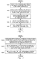
- FIG. 11 an illustration of a process for increasing a number of points in a point cloud in the form of a flowchart is depicted in accordance with an illustrative embodiment.
- the process illustrated in Figure 11 may be implemented using image processing system 102 in Figure 1 .
- the process begins by receiving a two-dimensional image from a first sensor system and a point cloud from a second sensor system (operation 1100).
- the two-dimensional image may be received from a first sensor system in the form of a camera system, such as camera system 118 in Figure 1 .
- the two-dimensional image may be a color image.
- the point cloud may be received from a second sensor system in the form of a light detection and ranging system, such as light detection and ranging system 130 in Figure 1 .
- Both the two-dimensional image and the point cloud may be of the same scene. However, depending on the implementation, the two-dimensional image and the point cloud may capture the same scene from the same or different perspectives.
- At least a portion of the points in the point cloud may be mapped to the two-dimensional image to form transformed points (operation 1102).
- a fused data array is created using the two-dimensional image and the transformed points (operation 1104).
- new points for the point cloud are identified using the fused data array (operation 1106).
- the new points are added to the point cloud to form a new point cloud (operation 1108), with the process terminating thereafter.
- the increased number of points in the new point cloud as compared to the original point cloud may provide the new point cloud with an increased resolution as compared to the original point cloud.
- the new point cloud may capture features in the scene more accurately than the original point cloud.
- the new point cloud may be used to perform a number of different operations such as, for example, without limitation, object identification, object classification, segmentation, scene visualization, and/or other types of operations.
- FIG. 12 an illustration of a process for mapping points in a point cloud to a two-dimensional image to form transformed points in the form of a flowchart is depicted in accordance with an illustrative embodiment.
- the process illustrated in Figure 12 may be used to implement operation 1102 in Figure 11 . Further, this process may be performed using fusion manager 142 in image processing system 102 in Figure 1 .
- the process begins by transforming the three-dimensional reference coordinate system for the point cloud into a three-dimensional camera-centric coordinate system to identify camera-centric coordinates for the points in the point cloud (operation 1200).
- the three-dimensional reference coordinate system may be, for example, a geographical coordinate system or some other type of real world coordinate system.
- the origin of the three-dimensional camera-centric coordinate system is the location of the camera system that generated the two-dimensional image.
- the rotation, R , and the translation, T may be identified using a transformation algorithm that includes a camera pose estimation algorithm, such as an efficient perspective-n-point camera pose estimation algorithm.
- This efficient perspective-n-point camera pose estimation algorithm identifies pose information for a pose of the camera system that generated the two-dimensional image.
- the pose of the camera system may be comprised of at least one of an orientation and position of the camera system.
- the transformation algorithm uses the pose information of the camera system to generate the camera-centric coordinates for the point.
- each of the initial transformed points may be a point corresponding to a pixel at a particular pixel location within the image plane of the two-dimensional image.
- the portion of the initial transformed points selected may include points having a row, u , that is greater than zero and less than or equal to the maximum number of rows in the two-dimensional image and having a column, v , that is greater than zero and less than or equal to the maximum number of columns in the two-dimensional image.
- the transformed points may only include pixel locations that are inside the two-dimensional image and not outside of the two-dimensional image.
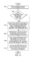
- FIG. 13 an illustration of a process for creating a fused data array in the form of a flowchart is depicted in accordance with an illustrative embodiment. The process illustrated in Figure 13 may be used to implement operation 1104 in Figure 11 .
- the process normalizes the depth values for each of the remaining transformed points to form normalized depth values (operation 1306).
- the predetermined minimum distance and the predetermined maximum distance may be computed automatically using, for example, a computer system.
- each element of the fused data array is associated with a data vector comprising a pixel location, a depth value, and original pixel data (operation 1308).
- the elements in the fused data array may have a one-to-one correspondence with the pixels in the two-dimensional image.
- the pixel location in the data vector associated with an element in the fused data array may include the row and column for the pixel corresponding to the element.
- the depth value in the data vector associated with the element may be the normalized distance identified for the transformed point that has been mapped to the pixel corresponding to the element. If no transformed point has been mapped to the pixel corresponding to the element, the depth value may be null.
- the original pixel data in the data vector associated with the element may include, for example, the red value, the green value, and the blue value for the pixel corresponding to the element.
- q i is the data vector associated with the i th element in the fused data array
- u i is the row for the pixel corresponding to the i th element
- v i is the column for the pixel corresponding to the i th element
- d i o is the depth value for a transformed point mapped to the pixel corresponding to the i th element
- r i ,g i ,b i are the red value, the green value, and the blue value for the pixel corresponding to the i th element.
- each of the elements in the fused data array may be indexed such that each of the elements may be capable of being uniquely referenced (operation 1310), with the process terminating thereafter.
- the elements in the fused data array corresponding to pixels to which transformed points have been mapped are matched elements.
- the elements in the fused data array corresponding to pixels to which no transformed points have been mapped are unmatched elements.
- FIG. 14 an illustration of a process for generating new depth values in the form of a flowchart is depicted in accordance with an illustrative embodiment. The process illustrated in Figure 14 may be used to implement operation 1106 in Figure 11 .
- the process begins by identifying a maximum number of iterations for processing of a fused data array (operation 1400). Next, a group of selected sizes for a window is identified for use in processing the fused data array (operation 1402). Thereafter, a size for the window is selected from the group of selected sizes (operation 1404).
- Each of the sizes in group of selected sizes may be an n by n size. In this manner, each window may have a length and width that are equal. In this illustrative example, each n may be an odd number.
- the window is moved to the location of an element in the fused data array (operation 1406).
- a determination is made as to whether the element is a matched element or an unmatched element (operation 1408).
- a matched element has a data vector with a non-null depth value.
- An unmatched element has a data vector with a null depth value. If the element is a matched element, a determination is made as to whether any unprocessed locations are present in the fused data array (operation 1410).
- the process returns to operation 1406 as described above. Otherwise, a determination is made as to whether any sizes in the group of selected sizes for the window are still present (operation 1412). If any sizes in the group of selected sizes for the window are still present, the process returns to operation 1404 as described above. Otherwise, one iteration is now considered as being completed and a determination is made as to whether the maximum number of iterations has been reached (operation 1414). If the maximum number of iterations has not been reached, the process returns to operation 1402 as described above. Otherwise, the process creates new points for a point cloud using new depth values generated for at least a portion of the unmatched elements in the fused data array (operation 1416), with the process terminating thereafter.
- the matched elements in the portion of the fused data array overlapped by the window meet the selected criteria if the number of matched elements is greater than a selected threshold and if at least one matched element is present in each quadrant of the portion of the fused data array overlapped by the window.
- a score is generated for each of the matched elements in the portion of the fused data array overlapped by the window (operation 1420).
- the score may be a goodness score for the matched element. The goodness score may be based on a combination of the distance of the transformed point mapped to the pixel corresponding to the element from the camera system and a dissimilarity of the matched element to the other matched elements.
- a feature may be, for example, pixel location, intensity, color, or some other type of feature.
- the response to that feature may be a value for that feature.
- the matched elements having a preselected number of the lowest scores are selected as support elements (operation 1422). For example, a number may be preselected for the desired number of support elements. This preselected number may be four, five, eight, ten, or some other number.
- the scores generated in operation 1420 may be sorted. If the preselected number is five, the matched elements having the five lowest scores are selected as the support elements.
- d l o ⁇ is the new depth value
- ⁇ 0 , ⁇ 1 , and ⁇ 2 are weights.
- any type of polynomial approximation algorithm may be used to solve for the new depth value using the depth values for the support elements.
- the process proceeds to operation 1410 as described above. In this manner, the new depth value is not added to the data vector corresponding to the element at which the window is centered. Rather, the depth value in this data vector remains null. However, if the new depth value is within the selected range, the new depth value is added to the data vector associated with the element at which the window is centered (operation 1430). The process then proceeds to operation 1410 as described above.
- FIG. 15 an illustration of a process for generating new points for a point cloud in the form of a flowchart is depicted in accordance with an illustrative example. The process illustrated in Figure 15 may be used to implement operation 1416 in Figure 14 .
- the process begins by denormalizing the new depth values generated for at least a portion of the unmatched elements in the fused data array (operation 1500). Each of these new depth values is used to create a new point for the point cloud.
- Camera-centric coordinates are generated for the new points for the point clouds using the denormalized depth values and the pixel locations in the data vectors for which the new depth values were generated (operation 1502).
- point locations for the new points in the three-dimensional reference coordinate system of the original point cloud are identified using the camera-centric coordinates (operation 1504), with the process terminating thereafter.
- the point locations in the three-dimensional reference coordinate system are identified using an inverse of the transformation algorithm used in operation 1200.
- each block in the flowcharts may represent a module, a segment, a function, and/or a portion of an operation or step.
- one or more of the blocks may be implemented using software, hardware, or a combination of the two.
- the hardware may, for example, take the form of integrated circuits that are manufactured or configured to perform one or more operations in the flowcharts.
- Data processing system 1600 may be used to implement one or more computers in computer system 104 in Figure 1 . Further, fusion manager 142, depth value generator 144, and/or point cloud manager 145 in Figure 1 may be implemented using data processing system 1600. Still further, a data processing system similar to data processing system 1600 may be implemented within first sensor system 106 and/or second sensor system 108 in Figure 1 .
- data processing system 1600 includes communications framework 1602, which provides communications between processor unit 1604, storage devices 1606, communications unit 1608, input/output unit 1610, and display 1612.
- communications framework 1602 may be implemented as a bus system.
- Processor unit 1604 is configured to execute instructions for software to perform a number of operations.
- Processor unit 1604 may comprise a number of processors, a multi-processor core, and/or some other type of processor, depending on the implementation.
- processor unit 1604 may take the form of a hardware unit, such as a circuit system, an application specific integrated circuit (ASIC), a programmable logic device, or some other suitable type of hardware unit.
- ASIC application specific integrated circuit
- Storage devices 1606 may be in communication with processor unit 1604 through communications framework 1602.
- a storage device also referred to as a computer readable storage device, is any piece of hardware capable of storing information on a temporary and/or permanent basis. This information may include, but is not limited to, data, program code, and/or other information.
- Memory 1614 and persistent storage 1616 are examples of storage devices 1606.
- Memory 1614 may take the form of, for example, a random access memory or some type of volatile or non-volatile storage device.
- Persistent storage 1616 may comprise any number of components or devices.
- persistent storage 1616 may comprise a hard drive, a flash memory, a rewritable optical disk, a rewritable magnetic tape, or some combination of the above.
- the media used by persistent storage 1616 may or may not be removable.
- Communications unit 1608 allows data processing system 1600 to communicate with other data processing systems and/or devices. Communications unit 1608 may provide communications using physical and/or wireless communications links.
- Input/output unit 1610 allows input to be received from and output to be sent to other devices connected to data processing system 1600.
- input/output unit 1610 may allow user input to be received through a keyboard, a mouse, and/or some other type of input device.
- input/output unit 1610 may allow output to be sent to a printer connected to data processing system 1600.
- Display 1612 is configured to display information to a user.
- Display 1612 may comprise, for example, without limitation, a monitor, a touch screen, a laser display, a holographic display, a virtual display device, and/or some other type of display device.
- processor unit 1604 may perform the processes of the different illustrative embodiments using computer-implemented instructions. These instructions may be referred to as program code, computer usable program code, or computer readable program code and may be read and executed by one or more processors in processor unit 1604.
- program code 1618 is located in a functional form on computer readable media 1620, which is selectively removable, and may be loaded onto or transferred to data processing system 1600 for execution by processor unit 1604.
- Program code 1618 and computer readable media 1620 together form computer program product 1622.
- computer readable media 1620 may be computer readable storage media 1624 or computer readable signal media 1626.
- Computer readable storage media 1624 is a physical or tangible storage device used to store program code 1618 rather than a medium that propagates or transmits program code 1618.
- Computer readable storage media 1624 may be, for example, without limitation, an optical or magnetic disk or a persistent storage device that is connected to data processing system 1600.
- program code 1618 may be transferred to data processing system 1600 using computer readable signal media 1626.
- Computer readable signal media 1626 may be, for example, a propagated data signal containing program code 1618. This data signal may be an electromagnetic signal, an optical signal, and/or some other type of signal that can be transmitted over physical and/or wireless communications links.
- data processing system 1600 in Figure 16 is not meant to provide architectural limitations to the manner in which the illustrative embodiments may be implemented.
- the different illustrative embodiments may be implemented in a data processing system that includes components in addition to or in place of those illustrated for data processing system 1600. Further, components shown in Figure 16 may be varied from the illustrative examples shown.
- the illustrative embodiments may be implemented using any hardware device or system capable of running program code.
- the data processing system may include organic components integrated with inorganic components and/or may be comprised entirely of organic components excluding a human being.
- a storage device may be comprised of an organic semiconductor.
- the illustrative embodiments provide a system and method for increasing the number of points in a point cloud.
- a two-dimensional image and a point cloud of a same scene are received. At least a portion of the points in the point cloud are mapped to the two-dimensional image to form transformed points.
- a fused data array is created using the two-dimensional image and the transformed points. New points for the point cloud are identified using the fused data array. The new points are added to the point cloud to form a new point cloud.
- the new point cloud formed using the image processing system described by the illustrative embodiments may allow a number of operations to be performed with a higher level of accuracy and/or efficiency as compared to the original point cloud. For example, object identification, object classification, segmentation, and/or other image processing operations may be performed more accurately using the new point cloud as compared to the original point cloud.
- the increased number of new points in the new point cloud may provide better visualization of the scene as compared to the original point cloud.
- the new point cloud may be used to better enhance the two-dimensional image as compared to the original point cloud.
- the image processing system described by the different illustrative embodiments allows this new point cloud having an increased number of points to be formed without making any assumptions about the types of objects in the scene, about the shapes of objects in the scene, and/or about the background of the scene.
- the process provided by the illustrative embodiments may form a new point cloud that more accurately represents the scene as compared to a process that makes assumptions about the scene to increase the number of points in the point cloud.
Landscapes
- Engineering & Computer Science (AREA)
- Physics & Mathematics (AREA)
- General Physics & Mathematics (AREA)
- Theoretical Computer Science (AREA)
- Multimedia (AREA)
- Signal Processing (AREA)
- Computer Graphics (AREA)
- Geometry (AREA)
- Software Systems (AREA)
- Image Processing (AREA)
- Image Analysis (AREA)
- Image Generation (AREA)
- Processing Or Creating Images (AREA)
- Length Measuring Devices By Optical Means (AREA)
Abstract
Description
- The present disclosure relates generally to point clouds and, in particular, to increasing the resolution of point clouds. Still more particularly, the present disclosure relates to a system and method for increasing the number of points in a point cloud to increase the resolution of the point cloud.
- A point cloud is a collection of points in a three-dimensional (3D) coordinate system that describe a three-dimensional scene. Typically, the points in a point cloud represent external surfaces of objects. A light detection and ranging (LIDAR) system is an example of one type of sensor system capable of generating a point cloud. Point clouds may also be generated using, for example, stereo camera systems, mobile laser imaging systems, and other types of sensor systems.
- Point clouds may be used for performing various operations such as, for example, object identification, object classification, scene visualization, segmentation, two-dimensional image data enhancement, and/or other types of operations. The level of performance with which these operations are performed using a point cloud may depend on the resolution of that point cloud.
- As used herein, the "resolution" of a point cloud may be the level of detail with which features in the scene captured by the point cloud may be discernible within the point cloud. The resolution of a point cloud may depend on the number of points in the point cloud and/or the point density of the points in one or more portions of the point cloud. As used herein, "point density" is a measure of the number of points per unit volume. A portion of a point cloud having a higher density than another portion of the point cloud may be less sparse than the other portion.
- In some situations, object identification, object classification, segmentation, and/or visualization of a scene using a sparse point cloud may yield inaccurate results. For example, a point cloud may be insufficiently dense to correctly identify or classify an object.
- Some currently available solutions for increasing the number of points in a point cloud include making assumptions about the objects in the scene. For example, assumptions may be made about the shape of an object in the scene and new points may be added to the point cloud based on those assumptions. However, with these types of solutions, the locations in the three-dimensional reference coordinate system at which the new points are added may be less accurate than desired.
- Further, some currently available solutions may be unable to account for actual holes or gaps in a scene. For example, with some currently available solutions, new points may be added to a point cloud at locations that represent actual holes or gaps in the scene. Still further, some currently available solutions may add points to a point cloud that connect objects that are unconnected in the scene, such as, for example, a tree top and the ground. Therefore, it would be desirable to have a method and apparatus that takes into account at least some of the issues discussed above, as well as other possible issues.
- In one illustrative embodiment, an apparatus comprises an image processing system. The image processing system is configured to map at least a portion of points in a point cloud of a scene to a two-dimensional image of the scene to form transformed points. The image processing system is configured to create a fused data array using the two-dimensional image and the transformed points. Further, the image processing system is configured to identify new points for the point cloud using the fused data array and add the new points to the point cloud to form a new point cloud.
- In another illustrative embodiment, an image processing system comprises a fusion manager, a depth value generator, and a point cloud manager. The fusion manager is configured to map at least a portion of points in a point cloud of a scene to a two-dimensional image of the scene to form transformed points and configured to create a fused data array using the two-dimensional image and the transformed points. The fused data array includes matched elements associated with filled data vectors comprising non-null depth values and unmatched elements associated with unfilled data vectors comprising null depth values. The depth value generator is configured to identify new depth values to replace at least a portion of the null depth values. The point cloud manager is configured to identify new points for the point cloud using the new depth values and add the new points to the point cloud to form a new point cloud.
- In yet another illustrative embodiment, a computer-implemented method for increasing a number of points in a point cloud is provided. A two-dimensional image of a scene and the point cloud of the scene are received. At least a portion of the points in the point cloud are mapped to the two-dimensional image to form transformed points. A fused data array is created using the two-dimensional image and the transformed points. New points for the point cloud are identified using the fused data array. The new points are added to the point cloud to form a new point cloud.
- Any of the preceding embodiments described herein, can also contemplate the following computer-implemented method as described in the clauses below.
- Clause 12. A computer-implemented method for increasing a number of points in a point cloud (132), the computer-implemented method comprising:
- receiving a two-dimensional image (121) of a scene (110) and the point cloud (132) of the scene (110);
- mapping at least a portion of the points in the point cloud (132) to the two-dimensional image (121) to form transformed points (146);
- creating a fused data array (150) using the two-dimensional image (121) and the transformed points (146);
- identifying new points (164) for the point cloud (132) using the fused data array (150); and
- adding the new points (164) to the point cloud (132) to form a new point cloud (162).
- Clause 13. The computer-implemented method of Clause 12, wherein mapping the at least a portion of the points in the point cloud (132) to the two-dimensional image (121) to form the transformed points (146) comprises:
- identifying pose information for a camera system;
- transforming a three-dimensional reference coordinate system for the point cloud (132) to a three-dimensional camera-centric coordinate system using the pose information to identify camera-centric coordinates for the points in the point cloud (132); and
- mapping the at least a portion of the points in the point cloud (132) having the camera-centric coordinates to pixel locations (124) in the two-dimensional image (121).
- Clause 14. The computer-implemented method of clause 12 or 13, wherein creating the fused data array (150) using the two-dimensional image (121) and the transformed points (146) comprises:
- forming the fused data array (150), wherein the fused data array (150) is comprised of elements (152) having a one-to-one correspondence with pixels in the two-dimensional image (121); and
- associating data vectors (154) with the elements (152) in the fused data array (150), wherein the data vectors (154) include filled data vectors (154) comprising non-null depth values and unfilled data vectors (154) comprising null depth values.
- Clause 15. The computer-implemented method of clause 14, wherein identifying the new points (164) for the point cloud (132) using the fused data array (150) comprises:
- generating new depth values (158) to replace at least a portion of the null depth values; and
- identifying the new points (164) for the point cloud (132) using the new depth values (158).
-
Clause 16. The computer-implemented method of clause 15, wherein generating the new depth values (158) to replace the at least a portion of the null depth values comprises:- centering a window at a location of an element in the fused data array (150), wherein the element is associated with an unfilled data vector (154) comprising a null depth value;
- identifying support elements (500) in a portion of the fused data array (150) overlapped by the window; and
- generating a new depth value (156) to replace the null depth value using the support elements (500) and a linear estimation algorithm.
- Clause 17. The computer-implemented method of
clause 16, wherein identifying the support elements (500) in the portion of the fused data array (150) overlapped by the window comprises:- determining whether matched elements (304, 306, 308, 310, 312, 314, 316) in the portion of the fused data array (150) overlapped by the window meet selected criteria;
- responsive to the matched elements (304, 306, 308, 310, 312, 314, 316) meeting the selected criteria, scoring each of the matched elements (304, 306, 308, 310, 312, 314, 316) with a goodness score;
- sorting the matched elements (304, 306, 308, 310, 312, 314, 316) by the goodness score; and
- selecting a portion of the matched elements (304, 306, 308, 310, 312, 314, 316) as the support elements (500).
- Clause 18. The computer-implemented method of
clause 16 or 17, further comprising:- repeating the steps of centering the window at the location of the element in the fused data array (150), identifying the support elements (500) in the portion of the fused data array (150) overlapped by the window, and generating the new depth value (156) to replace the null depth value using the support elements (500) and the linear estimation algorithm for each location in the fused data array (150).
- Clause 19. The computer-implemented method of any of clauses 15 to 18, wherein identifying the new points (164) for the point cloud (132) using the new depth values (158) comprises:
- identifying camera-centric coordinates within a three-dimensional camera-centric coordinate system for the new points (164) using the new depth values (158); and
- transforming the camera-centric coordinates to point locations within a three-dimensional reference coordinate system for the point cloud (132) to form the new points (164).
- Clause 20. The computer-implemented method of any of clauses 15 to 19, wherein generating the new depth values (158) to replace the at least a portion of the null depth values comprises:
- processing the fused data array (150) using windows to generate the new depth values (158).
- The features and functions can be achieved independently in various embodiments of the present disclosure or may be combined in yet other embodiments in which further details can be seen with reference to the following description and drawings.
- The novel features believed characteristic of the illustrative embodiments are set forth in the appended claims. The illustrative embodiments, however, as well as a preferred mode of use, further objectives and features thereof, will best be understood by reference to the following detailed description of an illustrative embodiment of the present disclosure when read in conjunction with the accompanying drawings, wherein:
-
Figure 1 is an example of an environment in which an image processing system may be used to process images and point clouds in the form of a block diagram in accordance with an illustrative embodiment; -
Figure 2 is an illustration of a fused data array in accordance with an illustrative embodiment; -
Figure 3 is an illustration of a portion of a fused data array overlapped by a window in accordance with an illustrative embodiment; -
Figure 4 is an illustration of a process for generating scores for each of a group of matched elements in accordance with an illustrative embodiment; -
Figure 5 is an illustration of a selection of support elements in accordance with an illustrative embodiment; -
Figure 6 is an illustration of the generation of a new depth value in accordance with an illustrative embodiment; -
Figure 7 is an illustration of a fused image in accordance with an illustrative embodiment; -
Figure 8 is an illustration of a comparison between two fused images in accordance with an illustrative embodiment; -
Figure 9 is an illustration of a comparison of a final fused image in accordance with an illustrative embodiment; -
Figure 10 is an illustration of a table of final fused images in accordance with an illustrative embodiment; -
Figure 11 is an illustration of a process for increasing a number of points in a point cloud in the form of a flowchart in accordance with an illustrative embodiment; -
Figure 12 is an illustration of a process for mapping points in a point cloud to a two-dimensional image to form transformed points in the form of a flowchart in accordance with an illustrative embodiment; -
Figure 13 is an illustration of a process for creating a fused data array in the form of a flowchart in accordance with an illustrative embodiment; -
Figure 14 is an illustration of a process for generating new depth values in the form of a flowchart in accordance with an illustrative embodiment; -
Figure 15 is an illustration of a process for generating new points for a point cloud in the form of a flowchart in accordance with an illustrative embodiment; and -
Figure 16 is an illustration of a data processing system in the form of a block diagram in accordance with an illustrative embodiment. - The different illustrative embodiments recognize and take into account different considerations. For example, the illustrative embodiments recognize and take into account that it may be desirable to have a method for increasing the number of points in a point cloud by adding new points to locations in the three-dimensional reference coordinate system for the point cloud that have a desired level of accuracy.
- Further, the illustrative embodiments recognize and take into account that a two-dimensional image of the same scene captured by a point cloud may be used to increase the number of points in a point cloud. However, the illustrative embodiments recognize and take into account that it may be desirable to process the two-dimensional image to increase the number of points in the point cloud without making assumptions about the scene and/or the shapes of objects in the scene captured in the two-dimensional image.
- Thus, the illustrative embodiments provide a system and method for increasing the number of points in a point cloud of a scene using a two-dimensional image of the scene. Further, this system and method may increase the number of points in the point cloud without making any assumptions about the scene.
- With reference now to
Figure 1 , an illustration of an image processing environment in the form of a block diagram is depicted in accordance with an illustrative embodiment. InFigure 1 ,image processing environment 100 is an example of an environment in whichimage processing system 102 may be used to process images and point clouds. - As depicted,
image processing system 102 may be implemented incomputer system 104.Computer system 104 may be comprised of one or more computers and/or other types of hardware. When more than one computer is present incomputer system 104, these computers may be in communication with one another. -
Image processing system 102 may be configured to receive data fromfirst sensor system 106 andsecond sensor system 108.First sensor system 106 andsecond sensor system 108 are configured to generate data aboutscene 110.Scene 110 may include features 111.Features 111 may include, for example, without limitation, objects 112.Objects 112 may include, for example, without limitation, any number of vehicles, buildings, manmade structures, people, animals, landscape features, and/or other types of objects. Further, features 111 may also include, for example, a background ofscene 110. - In these illustrative examples,
first sensor system 106 may take the form offirst imaging system 114.First imaging system 114 may be any system configured to generateimaging data 116 forscene 110. In one illustrative example,first imaging system 114 takes the form ofcamera system 118. Further,camera system 118 may take the form of an electro-optical camera system. -
Imaging data 116 may include, for example, without limitation,image 120. In particular,image 120 may be two-dimensional image 121. When generated by an electro-optical camera system,image 120 may be referred to as an electro-optical image. - As depicted,
image 120 may be comprised ofpixels 122.Pixels 122 may be arranged in a two-dimensional array comprised of rows and columns. In this illustrative example,pixel locations 124 may identify the locations ofpixels 122 within this array. As one illustrative example, each ofpixel locations 124 may identify a row and column for a corresponding pixel. - Additionally, each of
pixels 122 may be associated with pixel data. The pixel data for a pixel may include, for example, without limitation, a number of color values, an intensity value, and/or other values. The number of color values may include, for example, a red value, a green value, and a blue value based on the RGB color model. - In these illustrative examples,
second sensor system 108 may take the form ofsecond imaging system 126.Second imaging system 126 may be any system configured to generatepoint data 128 forscene 110. In one illustrative example,second imaging system 126 takes the form of light detection and rangingsystem 130. -
Point data 128 may includepoint cloud 132.Point cloud 132 may take the form of three-dimensional point cloud 133 in these illustrative examples.Point cloud 132 ofscene 110 may be generated from a different perspective thanimage 120 ofscene 110 in some illustrative examples. -
Point cloud 132 is comprised ofpoints 134 in a three-dimensional reference coordinate system. In these illustrative examples, each ofpoint locations 136 may identify the coordinates for a corresponding point in this three-dimensional reference coordinate system. In one illustrative example, the reference coordinate system may be a real world coordinate system such as, for example, a geographical coordinate system. -
Resolution 140 ofpoint cloud 132 may be an identification of the level of detail with which features 111 inscene 110 captured bypoint cloud 132 may be discernible withinpoint cloud 132. In some cases,resolution 140 ofpoint cloud 132 may depend onnumber 138 ofpoints 134 inpoint cloud 132. For example, asnumber 138 ofpoints 134 inpoint cloud 132 increases,resolution 140 ofpoint cloud 132 may also increase. -
Image processing system 102 is configured to receiveimage 120 generated bycamera system 118 andpoint cloud 132 generated by light detection and rangingsystem 130.Image processing system 102 usesimage 120 to increasenumber 138 ofpoint cloud 132, and therebyresolution 140 ofpoint cloud 132. More specifically,image processing system 102 may be configured to generate new points that may be added topoint cloud 132. - As depicted,
image processing system 102 may includefusion manager 142,depth value generator 144, andpoint cloud manager 145.Fusion manager 142 is configured to map at least a portion ofpoints 134 inpoint cloud 132 to image 120 to form transformed points 146. More specifically,fusion manager 142 is configured to map the point locations for at least a portion ofpoints 134 inpoint cloud 132 to pixel locations in the image plane ofimage 120. The image plane ofimage 120 may be the plane that lies within the two-dimensional array ofpixels 122. - Transformed
points 146 may be formed using, for example,transformation algorithm 148.Transformation algorithm 148 may include any number of processes, equations, and/or algorithms for mapping at least a portion ofpoints 134 to pixel locations in the image plane ofimage 120. In an illustrative example,transformation algorithm 148 may include a camera pose estimation algorithm such as, for example, an efficient perspective-n-point (EPnP) camera pose estimation algorithm. - The camera pose estimation algorithm may provide pose information for a pose of
camera system 118. The pose ofcamera system 118 may be comprised of at least one of an orientation and position ofcamera system 118. -
Fusion manager 142 usestransformation algorithm 148 to transform the three-dimensional reference coordinate system forpoint cloud 132 into a three-dimensional camera-centric coordinate system. In particular,fusion manager 142 may use the pose information forcamera system 118 provided by the camera post estimation algorithm to transform the three-dimensional reference coordinate system into the three-dimensional camera-centric coordinate system. - With this transformation, the origin of the three-dimensional reference coordinate system may be moved to the location of
camera system 118.Fusion manager 142 then identifies camera-centric coordinates forpoints 134 in the three-dimensional camera-centric coordinate system. - Thereafter,
fusion manager 142 is configured to map the camera-centric coordinates forpoints 134 to corresponding pixel locations in the image plane ofimage 120 to form transformed points 146. In this manner, the camera-centric coordinates for a point inpoint cloud 132 may be mapped to a pixel location that lies insideimage 120 or outside ofimage 120 but in the same image plane asimage 120. Transformedpoints 146 may include only those points that are mapped to pixel locations withinimage 120. -
Fusion manager 142 is configured to create fused data array 150 usingimage 120 and transformedpoints 146. Fused data array 150 includes data that has been fused together based onimage 120 andpoint cloud 132. - As depicted, fused data array 150 may include
elements 152. Each ofelements 152 may correspond to one ofpixels 122 inimage 120, and each ofpixels 122 may correspond to one ofelements 152. In particular,elements 152 may have a one-to-one correspondence withpixels 122 inimage 120. In this manner, fused data array 150 may have a same size as the array ofpixels 122 inimage 120. - Further, because each of transformed
points 146 corresponds to a pixel inimage 120, each of transformedpoints 146 may also correspond to the element in fused data array 150 that corresponds to that pixel. Each of transformedpoints 146 may be described as mapping to a corresponding one ofelements 152. - For example, transformed
points 146 may map to a first portion ofelements 152. This first portion of elements may be referred to as matched elements. However, a second portion ofelements 152 may not have any transformed points that map to these elements. The second portion ofelements 152 may be referred to as unmatched elements. - In these illustrative examples, each of
elements 152 may be associated with a data vector, such as, for example,data vector 154. As depicted,data vector 154 may includedepth value 156.Depth value 156 may be a distance between the transformed point corresponding to the element associated withdata vector 154 andcamera system 118 within the three-dimensional camera-centric coordinate system. - When the element associated with
data vector 154 is an unmatched element,depth value 156 may be a null or zero value. When the element associated withdata vector 154 is a matched element,depth value 156 may be a non-null or non-zero value.Data vector 154 may be referred to as an unfilled data vector whendepth value 156 is a null or zero value and a filled data vector whendepth value 156 is a non-null or non-zero value. In this manner, unmatched elements in fused data array 150 may be associated with unfilled data vectors and matched elements in fused data array 150 may be associated with filled data vectors. - Additionally, depending on the implementation,
data vector 154 may also include other data such as, for example,pixel location 157,original pixel data 159, and/or other types of data.Pixel location 157 may be the pixel location for the pixel corresponding to the element associated withdata vector 154.Original pixel data 159 may be the pixel data inimage 120 for the pixel corresponding to the element associated withdata vector 154. - In these illustrative examples,
depth value generator 144 is configured to generate new depth values 158 for at least a portion of the unfilled data vectors associated with unmatched elements in fused data array 150. In this manner,depth value generator 144 may identify new depth values 158 to replace at least a portion of the null depth values. The unfilled data vectors may then be filled, byfusion manager 142, with new depth values 158 to form modified fuseddata array 160. -
New depth values 158 may be generated using modified fuseddata array 160. In particular,depth value generator 144 may use windows of selected sizes to scan and process fused data array 150. Further, estimation techniques, such as linear estimation techniques, may be used to generate new depth values 158. An example of one implementation for the process of generating new depth values 158 is described inFigures 2-6 below. -
Point cloud manager 145 is configured to use modified fuseddata array 160 to createnew point cloud 162. In particular,point cloud manager 145 may use the portion of elements in fused data array 150 having data vectors filled with new depth values 158 to identifynew points 164 forpoint cloud 132. - As one illustrative example,
point cloud manager 145 may map each of the pixel locations for the pixels corresponding to the portion of elements in fused data array 150 having data vectors filled with new depth values 158 to camera-centric coordinates in the three-dimensional camera-centric coordinate system. These camera-centric coordinates may then be transformed into the three-dimensional reference coordinate system for the original point cloud,point cloud 132, to formnew points 164. This transformation may be performed using, for example, without limitation,inverse transformation algorithm 166.Inverse transformation algorithm 166 may be the inverse oftransformation algorithm 148 used byfusion manager 142. -
Point cloud manager 145 addsnew points 164 topoint cloud 132 to formnew point cloud 162. This process of addingnew points 164 topoint cloud 132 may be referred to as "backfilling"point cloud 132.New point cloud 162 may have a greater number of points thannumber 138 ofpoints 134 inpoint cloud 132. New points 164 may providenew point cloud 162 with an increased resolution as compare toresolution 140 ofpoint cloud 132.New point 164 may capturefeatures 111 inscene 110 with a desired level of accuracy. - Consequently,
new point cloud 162 may be used in the place ofpoint cloud 132 for performing any number of operations. For example, without limitation,new points 164 may enhance the visualization ofscene 110 innew point cloud 162 as compared topoint cloud 132. Further,new points 164 may allow one or more ofobjects 112 inscene 110 to be identified and/or classified usingnew point cloud 162 with a higher level of accuracy as compared to usingpoint cloud 132. - For example, initial fused
image 168 may be generated byfusion manager 142 usingimage 120 andpoint cloud 132. At least a portion of the points inpoint cloud 132 may be mapped to pixel locations inimage 120 and overlaid onimage 120 to create initial fusedimage 168. Final fusedimage 170 may be generated byfusion manager 142 usingimage 120 andnew point cloud 162. At least a portion of the points innew point cloud 162 may be mapped to pixel locations inimage 120 and overlaid onimage 120 to create final fusedimage 170. - The visualization of
scene 110 in final fusedimage 170 may be enhanced as compared to the visualization ofscene 110 in initial fusedimage 168. In particular, the greater number of points in final fusedimage 170 as compared to initial fusedimage 168 may enhance the visualization ofscene 110 in final fusedimage 170. - The illustration of
image processing environment 100 inFigure 1 is not meant to imply physical or architectural limitations to the manner in which an illustrative embodiment may be implemented. Other components in addition to or in place of the ones illustrated may be used. Some components may be optional. Also, the blocks are presented to illustrate some functional components. One or more of these blocks may be combined, divided, or combined and divided into different blocks when implemented in an illustrative embodiment. - For example, in some illustrative examples,
depth value generator 144 may be considered part offusion manager 142. In other illustrative examples,fusion manager 142 and/ordepth value generator 144 may be considered part ofpoint cloud manager 145. - In other illustrative examples, some other module in
image processing system 102 may be used to form initial fusedimage 168 and/or final fusedimage 170. In still other cases, some other data processing system or processor unit may be configured to processimage 120 andnew point cloud 162 to form final fusedimage 170. - Turning now to
Figures 2-6 , illustrations of a process for generating new depth values for unfilled data vectors associated with unmatched elements in a fused data array are depicted in accordance with an illustrative embodiment. The process illustrated inFigures 2-6 may be an example of one manner in which new depth values 158 inFigure 1 may be generated. Further, this process may be performed using, for example,depth value generator 144 inFigure 1 . - With reference now to
Figure 2 , an illustration of a fused data array is depicted in accordance with an illustrative embodiment. In this illustrative example, fuseddata array 200 may be an example of one implementation for fused data array 150 inFigure 1 . - In
Figure 2 , fuseddata array 200 may be the fusion ofimage 202 and transformedpoints 206.Image 202 may be an image generated by, for example,camera system 204. Transformedpoints 206 may include a portion of the points in a point cloud mapped to pixel locations inimage 202, and thereby, elements in fuseddata array 200. Fuseddata array 200 may have been generated by, for example,fusion manager 142 inFigure 1 . - As depicted,
depth value generator 144 may movewindow 208 along fuseddata array 200 in the direction ofarrow 210 andarrow 212 to process fuseddata array 200. For example,window 208 may be moved to the location of every element within fuseddata array 200. In this illustrative example,window 208 may have one of a group of selected sizes. As used herein, a "group of" items may include one or more items. In this manner, a group of selected sizes may include one or more selected sizes. - Fused
data array 200 may be fully scanned and processed using a window having each size in the group of selected sizes. Movingwindow 208 to the location of an element in fuseddata array 200 means centeringwindow 208 at that element in this illustrative example. When the element at whichwindow 208 is centered is an unmatched element, the portion of fuseddata array 200 overlapped bywindow 208 may be processed bydepth value generator 144 to identify a new depth value for the unfilled data vector associated with this unmatched element. - With reference now to
Figure 3 , an illustration of a portion of fuseddata array 200 overlapped bywindow 208 fromFigure 2 is depicted in accordance with an illustrative embodiment. In this illustrative example,portion 300 of fuseddata array 200 fromFigure 2 is overlapped bywindow 208. - In
Figure 3 , group of matchedelements 302 identify the elements inportion 300 of fuseddata array 200 to which a portion of transformedpoints 206 inFigure 2 have been mapped. All other elements (not shown in this view) inportion 300 of fuseddata array 200 may be unmatched elements to which transformed points have not been mapped. As depicted, group of matchedelements 302 includes matchedelements -
Depth value generator 144 first confirms that the depth value in the data vector associated with the element at whichwindow 208 is centered is a null depth value. If the depth value is a non-null depth value,depth value generator 144 moveswindow 208 to another location. If the depth value is a null depth value,depth value generator 144 continues processingportion 300 of fuseddata array 200. - In this illustrative example,
portion 300 of fuseddata array 200 is depicted divided intoquadrants Depth value generator 144 is configured to confirm that a sufficient number of matched elements are present inportion 300 of fuseddata array 200. Further,depth value generator 144 is configured to confirm that at least one matched element is present in each ofquadrants - Once
depth value generator 144 confirms that a sufficient number of matched elements are present inportion 300 of fuseddata array 200 and that at least one matched element is present in each ofquadrants depth value generator 144 may continue processingportion 300 of fuseddata array 200. When a sufficient number of matched elements are not present inportion 300 or when one ofquadrants depth value generator 144 may movewindow 208 to a next location along fuseddata array 200. - Turning now to
Figure 4 , an illustration of a process for generating scores for each of group of matchedelements 302 fromFigure 3 is depicted in accordance with an illustrative embodiment. InFigure 4 ,depth value generator 144 is configured to generate a score for each matched element in group of matchedelements 302. The score for a matched element may be based on the depth value in the filled data vector associated with the matched element and a similarity of the matched element to the other matched elements in group of matchedelements 302. - The depth value in the filled data vector associated with the matched element may be the distance between
camera system 204 and the location of the transformed point, which has been mapped to the matched element, within the three-dimensional camera-centric coordinate system. The depth values for group of matchedelements 302 may bedistances elements camera system 204. - The similarity of the matched element to the other matched elements in group of matched
elements 302 may be based on any number of features. These features may include, for example, without limitation, pixel location, color, intensity, and/or other types of features or data within a data vector. In this illustrative example, the similarity of the matched element to the other matched elements may be based on the distance between the pixel location identified in the data vector associated with the matched element andideal pixel location 400. The pixel location may be the same as the location for the matched element within fuseddata array 200. - With reference now to
Figure 5 , an illustration of a selection of support elements is depicted in accordance with an illustrative embodiment. In this illustrative example, the scores generated for group of matchedelements 302, as described inFigure 4 , may be sorted, or ordered. - The desired number of support elements may be five support elements in this illustrative example. The five matched elements having the five lowest scores are selected as
support elements 500.Support elements 500 include matchedelements - In this illustrative example, support
elements 500 may be selected such that the number of new points created for actual holes and/or gaps in the scene captured byimage 202 is reduced. Further,support elements 500 may be selected such that the new points created actually represent an external surface of an object. - Turning now to
Figure 6 , an illustration of the generation of a new depth value is depicted in accordance with an illustrative embodiment. In this illustrative example, supportelements 500 fromFigure 5 may be used to generate a new depth value forelement 600 at whichwindow 208 was centered.Element 600 is atlocation 602 in fuseddata array 200, which may be the center location ofportion 300 of fuseddata array 200. - The new depth value for
element 600 may be generated using, for example, linear estimation. In particular, a linear estimation algorithm may use the depth value in the filled data vector associated with each ofsupport elements 500 to estimate the new depth value forelement 600. This new depth value may be used to fill the data vector associated withelement 600. - The process described in
Figures 3-6 may be repeated for each location in fuseddata array 200 to whichwindow 208 fromFigure 2 is moved. Further, the entire process described inFigures 2-6 may be repeated using windows of different selected sizes. - In this manner, the entire fused
data array 200 may be scanned and processed with a window having each of a group of selected sizes. Still further, this entire process of using the windows having the group of selected sizes may be iterated any number of times to fill at least a portion of the unfilled data vectors associated with the unmatched elements in fuseddata array 200. - The illustrations in
Figures 2-6 are not meant to imply physical or architectural limitations to the manner in which an illustrative embodiment may be implemented. These illustrations are presented to describe the concept of generating new depth values in an abstract manner. - With reference now to
Figure 7 , an illustration of a fused image is depicted in accordance with an illustrative embodiment. Fusedimage 700 may be an example of one implementation for fused data array 150 inFigure 1 . Fusedimage 700 may be a combination ofimage 702 and transformedpoints 704. In this illustrative example, each pixel in fusedimage 700 may be associated with a data vector, such asdata vector 154 inFigure 1 . - Turning now to
Figure 8 , an illustration of a comparison between two fused images is depicted in accordance with an illustrative embodiment. In this illustrative example, initial fusedimage 800 is an example of one implementation for initial fusedimage 168 inFigure 1 . Further, final fusedimage 802 is an example of one implementation for final fusedimage 170 inFigure 1 . - As depicted, initial fused
image 800 is a fusion ofimage 804 and transformedpoints 806. Transformedpoints 806 may include points mapped from an original point cloud, such as, for example,point cloud 132 inFigure 1 . Final fusedimage 802 is a fusion of thesame image 804 and transformedpoints 808. Transformedpoints 808 may include points mapped from a new point cloud, such as, for example,new point cloud 162 inFigure 1 . The scene captured inimage 804 may be better realized by transformedpoints 808 in final fusedimage 802 as compared to transformedpoints 806 in initial fusedimage 800. - With reference now to
Figure 9 , an illustration of a comparison of a final fused image generated when support elements are used and a final fused image generated when support elements are not used is depicted in accordance with an illustrative embodiment. In this illustrative example, a comparison of final fusedimage 900 and final fusedimage 902 is depicted. These final fused images are examples of implementations for final fusedimage 170 inFigure 1 . - Final fused
image 900 is a fusion ofimage 904 and transformedpoints 906. Final fusedimage 902 is a fusion of thesame image 904 and transformedpoints 908. Transformedpoints 906 and transformedpoints 908 may both include points mapped from a corresponding new point cloud to which new points have been added. - However, transformed
points 906 may include points from a new point cloud generated without the use of support elements. Transformedpoints 908 may include points from a new point cloud generated with the use of support elements. As depicted, the surface and shape of the top of the building depicted inportion 912 of final fusedimage 900 may be less clearly defined and less accurate than the surface and shape of top of the building depicted inportion 914 of final fusedimage 902. - With reference now to
Figure 10 , an illustration of a table of final fused images is depicted in accordance with an illustrative embodiment. InFigure 10 , table 1000 includescolumn 1002,column 1004,row 1006, androw 1008. -
Column 1002 includes final fusedimage 1010 and final fusedimage 1014 generated using two iterations of scanning windows having a group of selected sizes across a fused data array.Column 1004 includes final fusedimage 1012 and final fusedimage 1016 generated using ten iterations of scanning windows having a group of selected sizes across a fused data array. -
Row 1006 includes final fusedimage 1010 and final fusedimage 1012 generated using eight sizes of windows per iteration. Further,row 1008 includes final fusedimage 1014 and final fusedimage 1016 generated using sixteen sizes of windows per iteration. - As depicted, the number of points included in a final fused image increases as the number of iterations and the number of sizes for the windows per iteration increase. As the number of points in a final fused image increases, visualization of the scene within the final fused image may be enhanced.
- The illustrations of fused images in
Figures 7-10 are not meant to imply physical or architectural limitations to the manner in which an illustrative embodiment may be implemented. These fused images are examples of how fused images, such as initial fusedimage 168 and final fusedimage 170 fromFigure 1 , may be implemented. - With reference now to
Figure 11 , an illustration of a process for increasing a number of points in a point cloud in the form of a flowchart is depicted in accordance with an illustrative embodiment. The process illustrated inFigure 11 may be implemented usingimage processing system 102 inFigure 1 . - The process begins by receiving a two-dimensional image from a first sensor system and a point cloud from a second sensor system (operation 1100). In
operation 1100, the two-dimensional image may be received from a first sensor system in the form of a camera system, such ascamera system 118 inFigure 1 . In this illustrative example, the two-dimensional image may be a color image. Further, the point cloud may be received from a second sensor system in the form of a light detection and ranging system, such as light detection and rangingsystem 130 inFigure 1 . - Both the two-dimensional image and the point cloud may be of the same scene. However, depending on the implementation, the two-dimensional image and the point cloud may capture the same scene from the same or different perspectives.
- Next, at least a portion of the points in the point cloud may be mapped to the two-dimensional image to form transformed points (operation 1102). Next, a fused data array is created using the two-dimensional image and the transformed points (operation 1104).
- Thereafter, new points for the point cloud are identified using the fused data array (operation 1106). The new points are added to the point cloud to form a new point cloud (operation 1108), with the process terminating thereafter. The increased number of points in the new point cloud as compared to the original point cloud may provide the new point cloud with an increased resolution as compared to the original point cloud.
- In other words, the new point cloud may capture features in the scene more accurately than the original point cloud. The new point cloud may be used to perform a number of different operations such as, for example, without limitation, object identification, object classification, segmentation, scene visualization, and/or other types of operations.
- With reference now to
Figure 12 , an illustration of a process for mapping points in a point cloud to a two-dimensional image to form transformed points in the form of a flowchart is depicted in accordance with an illustrative embodiment. The process illustrated inFigure 12 may be used to implementoperation 1102 inFigure 11 . Further, this process may be performed usingfusion manager 142 inimage processing system 102 inFigure 1 . - The process begins by transforming the three-dimensional reference coordinate system for the point cloud into a three-dimensional camera-centric coordinate system to identify camera-centric coordinates for the points in the point cloud (operation 1200). The three-dimensional reference coordinate system may be, for example, a geographical coordinate system or some other type of real world coordinate system. The origin of the three-dimensional camera-centric coordinate system is the location of the camera system that generated the two-dimensional image.
- For example, for each point at a given location, Xp,Yp,Zp , in the three-dimensional reference coordinate system, the camera-centric coordinates are identified as follows:

- The rotation, R , and the translation, T , may be identified using a transformation algorithm that includes a camera pose estimation algorithm, such as an efficient perspective-n-point camera pose estimation algorithm. This efficient perspective-n-point camera pose estimation algorithm identifies pose information for a pose of the camera system that generated the two-dimensional image. The pose of the camera system may be comprised of at least one of an orientation and position of the camera system. The transformation algorithm uses the pose information of the camera system to generate the camera-centric coordinates for the point.
- Next, the points having the camera-centric coordinates are mapped to pixel locations in an image plane for the two-dimensional image to form initial transformed points (operation 1202). Each of the initial transformed points may be a point corresponding to a pixel at a particular pixel location within the image plane of the two-dimensional image. For example, each point may be mapped to a pixel location, u,v , as follows:
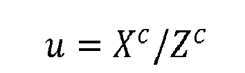

- Thereafter, a portion of the initial transformed points are selected based on selected criteria to form the transformed points (operation 1204), with the process terminating thereafter. In
operation 1204, the portion of the initial transformed points selected may include points having a row, u , that is greater than zero and less than or equal to the maximum number of rows in the two-dimensional image and having a column, v , that is greater than zero and less than or equal to the maximum number of columns in the two-dimensional image. In this manner, the transformed points may only include pixel locations that are inside the two-dimensional image and not outside of the two-dimensional image. - With reference now to
Figure 13 , an illustration of a process for creating a fused data array in the form of a flowchart is depicted in accordance with an illustrative embodiment. The process illustrated inFigure 13 may be used to implementoperation 1104 inFigure 11 . - The process begins by identifying a distance for each of the transformed points (operation 1300). This distance may be the distance between the camera-centric coordinates for the transformed point and the camera system. The distance may be identified as follows:

- Thereafter, a determination is made as to whether any of the transformed points have been mapped to a same pixel location (operation 1302). If any of the transformed points have been mapped to the same pixel location, then for each pixel location to which multiple transformed points have been mapped, the transformed point that is closest to the camera system is kept and the other transformed points are discarded (operation 1304).
- Next, the process normalizes the depth values for each of the remaining transformed points to form normalized depth values (operation 1306). For example, for each remaining transformed point, i , the normalized distance is identified as follows:


operation 1300;

- Thereafter, the fused data array is created in which each element of the fused data array is associated with a data vector comprising a pixel location, a depth value, and original pixel data (operation 1308). The elements in the fused data array may have a one-to-one correspondence with the pixels in the two-dimensional image. The pixel location in the data vector associated with an element in the fused data array may include the row and column for the pixel corresponding to the element. The depth value in the data vector associated with the element may be the normalized distance identified for the transformed point that has been mapped to the pixel corresponding to the element. If no transformed point has been mapped to the pixel corresponding to the element, the depth value may be null. The original pixel data in the data vector associated with the element may include, for example, the red value, the green value, and the blue value for the pixel corresponding to the element.
- In this manner, the data vector associated with an element in the fused data array may be represented as follows:


- Next, each of the elements in the fused data array may be indexed such that each of the elements may be capable of being uniquely referenced (operation 1310), with the process terminating thereafter. For example, each element may be indexed as follows:

- The elements in the fused data array corresponding to pixels to which transformed points have been mapped are matched elements. The elements in the fused data array corresponding to pixels to which no transformed points have been mapped are unmatched elements.
- With reference again to
operation 1302, if none of the transformed points have been mapped to same pixel location, the process proceeds tooperation 1306 as described above. In this manner, the process described inFigure 13 may be used to create a fused data array, such as fused data array 150 inFigure 1 . - With reference now to
Figure 14 , an illustration of a process for generating new depth values in the form of a flowchart is depicted in accordance with an illustrative embodiment. The process illustrated inFigure 14 may be used to implementoperation 1106 inFigure 11 . - The process begins by identifying a maximum number of iterations for processing of a fused data array (operation 1400). Next, a group of selected sizes for a window is identified for use in processing the fused data array (operation 1402). Thereafter, a size for the window is selected from the group of selected sizes (operation 1404). Each of the sizes in group of selected sizes may be an n by n size. In this manner, each window may have a length and width that are equal. In this illustrative example, each n may be an odd number.
- The window is moved to the location of an element in the fused data array (operation 1406). A determination is made as to whether the element is a matched element or an unmatched element (operation 1408). A matched element has a data vector with a non-null depth value. An unmatched element has a data vector with a null depth value. If the element is a matched element, a determination is made as to whether any unprocessed locations are present in the fused data array (operation 1410).
- If any unprocessed locations are present in the fused data array, the process returns to
operation 1406 as described above. Otherwise, a determination is made as to whether any sizes in the group of selected sizes for the window are still present (operation 1412). If any sizes in the group of selected sizes for the window are still present, the process returns tooperation 1404 as described above. Otherwise, one iteration is now considered as being completed and a determination is made as to whether the maximum number of iterations has been reached (operation 1414). If the maximum number of iterations has not been reached, the process returns tooperation 1402 as described above. Otherwise, the process creates new points for a point cloud using new depth values generated for at least a portion of the unmatched elements in the fused data array (operation 1416), with the process terminating thereafter. - With reference again to
operation 1408, if the element is an unmatched element, a determination is made as to whether the matched elements in the portion of a fused data array overlapped by the window meets selected criteria (operation 1418). The matched elements in the portion of the fused data array overlapped by the window meet the selected criteria if the number of matched elements is greater than a selected threshold and if at least one matched element is present in each quadrant of the portion of the fused data array overlapped by the window. - If the matched elements do not meet the selected criteria, the process proceeds to
operation 1410 as described above. Otherwise, a score is generated for each of the matched elements in the portion of the fused data array overlapped by the window (operation 1420). For example, the score may be a goodness score for the matched element. The goodness score may be based on a combination of the distance of the transformed point mapped to the pixel corresponding to the element from the camera system and a dissimilarity of the matched element to the other matched elements. - With n matched elements in the portion of the fused data array overlapped by the window, the goodness score may be generated as follows:


where Gi is the goodness score of the ith matched element; M i is a dissimilarity score for the ith matched element; Δ i is a distance measurement for the ith matched element; j is an index for the n matched elements; F is a response to a feature; m is the number of features;

- In this illustrative example, a feature may be, for example, pixel location, intensity, color, or some other type of feature. The response to that feature may be a value for that feature.
- Next, the matched elements having a preselected number of the lowest scores are selected as support elements (operation 1422). For example, a number may be preselected for the desired number of support elements. This preselected number may be four, five, eight, ten, or some other number. In
operation 1422, the scores generated inoperation 1420 may be sorted. If the preselected number is five, the matched elements having the five lowest scores are selected as the support elements. - A determination is then made as to whether a support element is present in each quadrant (operation 1424). If a support element is not present in each quadrant, the process proceeds to
operation 1410 as described above. Otherwise, a new depth value is generated for the element at which the window is centered using a linear estimation algorithm and the support elements (operation 1426). - In
operation 1426, the new depth value may be identified using a linear system such as, for example:

- Thereafter, a determination is made as to whether the new depth value is within a selected range (operation 1428). The new depth value may be within the selected range if


where
- If the new depth value is not within the selected range, the process proceeds to
operation 1410 as described above. In this manner, the new depth value is not added to the data vector corresponding to the element at which the window is centered. Rather, the depth value in this data vector remains null. However, if the new depth value is within the selected range, the new depth value is added to the data vector associated with the element at which the window is centered (operation 1430). The process then proceeds tooperation 1410 as described above. - With reference now to
Figure 15 , an illustration of a process for generating new points for a point cloud in the form of a flowchart is depicted in accordance with an illustrative example. The process illustrated inFigure 15 may be used to implementoperation 1416 inFigure 14 . - The process begins by denormalizing the new depth values generated for at least a portion of the unmatched elements in the fused data array (operation 1500). Each of these new depth values is used to create a new point for the point cloud. The new depth values may be denormalized as follows:


- Camera-centric coordinates are generated for the new points for the point clouds using the denormalized depth values and the pixel locations in the data vectors for which the new depth values were generated (operation 1502). The camera-centric coordinates are generated as follows:


- Thereafter, point locations for the new points in the three-dimensional reference coordinate system of the original point cloud are identified using the camera-centric coordinates (operation 1504), with the process terminating thereafter. The point locations in the three-dimensional reference coordinate system are identified using an inverse of the transformation algorithm used in
operation 1200. For example, the point locations may be identified as follows:
- The flowcharts in the different depicted embodiments illustrate the architecture, functionality, and operation of some possible implementations of the system and method described in the illustrative embodiments. In this regard, each block in the flowcharts may represent a module, a segment, a function, and/or a portion of an operation or step. For example, one or more of the blocks may be implemented using software, hardware, or a combination of the two. The hardware may, for example, take the form of integrated circuits that are manufactured or configured to perform one or more operations in the flowcharts.
- In some alternative implementations of an illustrative embodiment, the function or functions noted in the blocks may occur out of the order noted in the figures. For example, in some cases, two blocks shown in succession may be executed substantially concurrently, or performed in the reverse order, depending on the particular implementation. Also, other blocks may be added to the illustrated blocks in a flowchart.
- Turning now to
Figure 16 , an illustration of a data processing system in the form of a block diagram is depicted in accordance with an illustrative embodiment.Data processing system 1600 may be used to implement one or more computers incomputer system 104 inFigure 1 . Further,fusion manager 142,depth value generator 144, and/orpoint cloud manager 145 inFigure 1 may be implemented usingdata processing system 1600. Still further, a data processing system similar todata processing system 1600 may be implemented withinfirst sensor system 106 and/orsecond sensor system 108 inFigure 1 . - As depicted,
data processing system 1600 includescommunications framework 1602, which provides communications betweenprocessor unit 1604,storage devices 1606,communications unit 1608, input/output unit 1610, anddisplay 1612. In some cases,communications framework 1602 may be implemented as a bus system. -
Processor unit 1604 is configured to execute instructions for software to perform a number of operations.Processor unit 1604 may comprise a number of processors, a multi-processor core, and/or some other type of processor, depending on the implementation. In some cases,processor unit 1604 may take the form of a hardware unit, such as a circuit system, an application specific integrated circuit (ASIC), a programmable logic device, or some other suitable type of hardware unit. - Instructions for the operating system, applications, and/or programs run by
processor unit 1604 may be located instorage devices 1606.Storage devices 1606 may be in communication withprocessor unit 1604 throughcommunications framework 1602. As used herein, a storage device, also referred to as a computer readable storage device, is any piece of hardware capable of storing information on a temporary and/or permanent basis. This information may include, but is not limited to, data, program code, and/or other information. -
Memory 1614 andpersistent storage 1616 are examples ofstorage devices 1606.Memory 1614 may take the form of, for example, a random access memory or some type of volatile or non-volatile storage device.Persistent storage 1616 may comprise any number of components or devices. For example,persistent storage 1616 may comprise a hard drive, a flash memory, a rewritable optical disk, a rewritable magnetic tape, or some combination of the above. The media used bypersistent storage 1616 may or may not be removable. -
Communications unit 1608 allowsdata processing system 1600 to communicate with other data processing systems and/or devices.Communications unit 1608 may provide communications using physical and/or wireless communications links. - Input/
output unit 1610 allows input to be received from and output to be sent to other devices connected todata processing system 1600. For example, input/output unit 1610 may allow user input to be received through a keyboard, a mouse, and/or some other type of input device. As another example, input/output unit 1610 may allow output to be sent to a printer connected todata processing system 1600. -
Display 1612 is configured to display information to a user.Display 1612 may comprise, for example, without limitation, a monitor, a touch screen, a laser display, a holographic display, a virtual display device, and/or some other type of display device. - In this illustrative example, the processes of the different illustrative embodiments may be performed by
processor unit 1604 using computer-implemented instructions. These instructions may be referred to as program code, computer usable program code, or computer readable program code and may be read and executed by one or more processors inprocessor unit 1604. - In these examples,
program code 1618 is located in a functional form on computerreadable media 1620, which is selectively removable, and may be loaded onto or transferred todata processing system 1600 for execution byprocessor unit 1604.Program code 1618 and computerreadable media 1620 together formcomputer program product 1622. In this illustrative example, computerreadable media 1620 may be computerreadable storage media 1624 or computerreadable signal media 1626. - Computer
readable storage media 1624 is a physical or tangible storage device used to storeprogram code 1618 rather than a medium that propagates or transmitsprogram code 1618. Computerreadable storage media 1624 may be, for example, without limitation, an optical or magnetic disk or a persistent storage device that is connected todata processing system 1600. - Alternatively,
program code 1618 may be transferred todata processing system 1600 using computerreadable signal media 1626. Computerreadable signal media 1626 may be, for example, a propagated data signal containingprogram code 1618. This data signal may be an electromagnetic signal, an optical signal, and/or some other type of signal that can be transmitted over physical and/or wireless communications links. - The illustration of
data processing system 1600 inFigure 16 is not meant to provide architectural limitations to the manner in which the illustrative embodiments may be implemented. The different illustrative embodiments may be implemented in a data processing system that includes components in addition to or in place of those illustrated fordata processing system 1600. Further, components shown inFigure 16 may be varied from the illustrative examples shown. - The illustrative embodiments may be implemented using any hardware device or system capable of running program code. As one illustrative example, the data processing system may include organic components integrated with inorganic components and/or may be comprised entirely of organic components excluding a human being. For example, a storage device may be comprised of an organic semiconductor.
- Thus, the illustrative embodiments provide a system and method for increasing the number of points in a point cloud. In one illustrative embodiment, a two-dimensional image and a point cloud of a same scene are received. At least a portion of the points in the point cloud are mapped to the two-dimensional image to form transformed points. A fused data array is created using the two-dimensional image and the transformed points. New points for the point cloud are identified using the fused data array. The new points are added to the point cloud to form a new point cloud.
- The new point cloud formed using the image processing system described by the illustrative embodiments may allow a number of operations to be performed with a higher level of accuracy and/or efficiency as compared to the original point cloud. For example, object identification, object classification, segmentation, and/or other image processing operations may be performed more accurately using the new point cloud as compared to the original point cloud.
- Further, the increased number of new points in the new point cloud may provide better visualization of the scene as compared to the original point cloud. Still further, the new point cloud may be used to better enhance the two-dimensional image as compared to the original point cloud.
- The image processing system described by the different illustrative embodiments allows this new point cloud having an increased number of points to be formed without making any assumptions about the types of objects in the scene, about the shapes of objects in the scene, and/or about the background of the scene. In this manner, the process provided by the illustrative embodiments may form a new point cloud that more accurately represents the scene as compared to a process that makes assumptions about the scene to increase the number of points in the point cloud.
- The description of the different illustrative embodiments has been presented for purposes of illustration and description, and is not intended to be exhaustive or limited to the embodiments in the form disclosed. Many modifications and variations will be apparent to those of ordinary skill in the art. Further, different illustrative embodiments may provide different features as compared to other illustrative embodiments. The embodiment or embodiments selected are chosen and described in order to best explain the principles of the embodiments, the practical application, and to enable others of ordinary skill in the art to understand the disclosure for various embodiments with various modifications as are suited to the particular use contemplated.
Claims (15)
- An apparatus comprising:an image processing system (102) configured to map at least a portion of points (134) in a point cloud (132) of a scene (110) to a two-dimensional image (121) of the scene (110) to form transformed points (146); create a fused data array (150) using the two-dimensional image (121) and the transformed points (146); identify new points (164) for the point cloud (132) using the fused data array (150); and add the new points (164) to the point cloud (132) to form a new point cloud (162).
- The apparatus of claim 1, wherein the image processing system (102) comprises:a fusion manager (142) configured to map the at least a portion of the points in the point cloud (132) to the two-dimensional image (121) to form the transformed points (146) and configured to create the fused data array (150) using the two-dimensional image (121) and the transformed points (146).
- The apparatus of claim 1 or 2, wherein the fused data array (150) comprises matched elements (304, 306, 308, 310, 312, 314, 316) associated with filled data vectors (154) comprising non-null depth values and unmatched elements associated with unfilled data vectors (154) comprising null depth values.
- The apparatus of any of claims 1 to 3, wherein the image processing system (102) further comprises:a depth value generator (144) configured to identify new depth values (158) to replace at least a portion of the null depth values.
- The apparatus of any of claims 1 to 4, wherein the image processing system (102) further comprises:a point cloud manager (145) configured to identify the new points (164) for the point cloud (132) using the new depth values (158).
- The apparatus of claim 5, wherein the point cloud manager (145) is further configured to add the new points (164) to the point cloud (132) to form the new point cloud (162).
- The apparatus of any of claims 1 to 6, wherein the fused data array (150) is comprised of elements (152), wherein each of the elements (152) is associated with a data vector (154) comprising at least one of a pixel location (157), a depth value, and original pixel data (159).
- The apparatus of any of claims 1 to 7, further comprising:a first sensor system configured to generate the two-dimensional image (121); anda second sensor system configured to generate the point cloud (132).
- The apparatus of claim 8, wherein the first sensor system is a camera system and wherein the second sensor system is a light detection and ranging system.
- The apparatus of claim 9, wherein the image processing system (102) is configured to map the at least a portion of the points in the point cloud (132) to the two-dimensional image (121) using pose information for the camera system.
- An image processing system (102) comprising:a fusion manager (142) configured to map at least a portion of points (134) in a point cloud (132) of a scene (110) to a two-dimensional image (121) of the scene (110) to form transformed points (146) and configured to create a fused data array (150) using the two-dimensional image (121) and the transformed points (146),wherein the fused data array (150) includes matched elements (304, 306, 308, 310, 312, 314, 316) associated with filled data vectors (154) comprising non-null depth values and unmatched elements associated with unfilled data vectors (154) comprising null depth values;a depth value generator (144) configured to identify new depth values (158) to replace at least a portion of the null depth values; anda point cloud manager (145) configured to identify new points (164) for the point cloud (132) using the new depth values (158) and add the new points (164) to the point cloud (132) to form a new point cloud (162).
- A computer-implemented method for increasing a number of points in a point cloud (132), the computer-implemented method comprising:receiving a two-dimensional image (121) of a scene (110) and the point cloud (132) of the scene (110);mapping at least a portion of the points in the point cloud (132) to the two-dimensional image (121) to form transformed points (146);creating a fused data array (150) using the two-dimensional image (121) and the transformed points (146);identifying new points (164) for the point cloud (132) using the fused data array (150); andadding the new points (164) to the point cloud (132) to form a new point cloud (162).
- The computer-implemented method of claim 12, wherein mapping the at least a portion of the points in the point cloud (132) to the two-dimensional image (121) to form the transformed points (146) comprises:identifying pose information for a camera system;transforming a three-dimensional reference coordinate system for the point cloud (132) to a three-dimensional camera-centric coordinate system using the pose information to identify camera-centric coordinates for the points in the point cloud (132); andmapping the at least a portion of the points in the point cloud (132) having the camera-centric coordinates to pixel locations (124) in the two-dimensional image (121).
- The computer-implemented method of claim 12 or 13, wherein creating the fused data array (150) using the two-dimensional image (121) and the transformed points (146) comprises:forming the fused data array (150), wherein the fused data array (150) is comprised of elements (152) having a one-to-one correspondence with pixels in the two-dimensional image (121); andassociating data vectors (154) with the elements (152) in the fused data array (150), wherein the data vectors (154) include filled data vectors (154) comprising non-null depth values and unfilled data vectors (154) comprising null depth values.
- The computer-implemented method of any of claims 12 to 14, wherein identifying the new points (164) for the point cloud (132) using the fused data array (150) comprises:generating new depth values (158) to replace at least a portion of the null depth values; andidentifying the new points (164) for the point cloud (132) using the new depth values (158).
Applications Claiming Priority (1)
| Application Number | Priority Date | Filing Date | Title |
|---|---|---|---|
| US13/673,429 US9811880B2 (en) | 2012-11-09 | 2012-11-09 | Backfilling points in a point cloud |
Publications (2)
| Publication Number | Publication Date |
|---|---|
| EP2731075A1 true EP2731075A1 (en) | 2014-05-14 |
| EP2731075B1 EP2731075B1 (en) | 2018-06-20 |
Family
ID=49554009
Family Applications (1)
| Application Number | Title | Priority Date | Filing Date |
|---|---|---|---|
| EP13190777.6A Active EP2731075B1 (en) | 2012-11-09 | 2013-10-30 | Backfilling points in a point cloud |
Country Status (8)
| Country | Link |
|---|---|
| US (1) | US9811880B2 (en) |
| EP (1) | EP2731075B1 (en) |
| JP (1) | JP5778237B2 (en) |
| KR (1) | KR102096673B1 (en) |
| CN (1) | CN103810744B (en) |
| AU (1) | AU2013227985B2 (en) |
| BR (1) | BR102013028714B1 (en) |
| CA (1) | CA2826534C (en) |
Families Citing this family (41)
| Publication number | Priority date | Publication date | Assignee | Title |
|---|---|---|---|---|
| US20140363073A1 (en) * | 2013-06-11 | 2014-12-11 | Microsoft Corporation | High-performance plane detection with depth camera data |
| US10262462B2 (en) | 2014-04-18 | 2019-04-16 | Magic Leap, Inc. | Systems and methods for augmented and virtual reality |
| CN105469447A (en) * | 2014-09-11 | 2016-04-06 | 富泰华工业(深圳)有限公司 | Point-cloud boundary right-angle side repairing system and method |
| US10032311B1 (en) * | 2014-09-29 | 2018-07-24 | Rockwell Collins, Inc. | Synthetic image enhancing system, device, and method |
| US9772405B2 (en) | 2014-10-06 | 2017-09-26 | The Boeing Company | Backfilling clouds of 3D coordinates |
| FR3028988B1 (en) * | 2014-11-20 | 2018-01-19 | Commissariat A L'energie Atomique Et Aux Energies Alternatives | METHOD AND APPARATUS FOR REAL-TIME ADAPTIVE FILTERING OF BURNED DISPARITY OR DEPTH IMAGES |
| CN105701861A (en) * | 2014-11-28 | 2016-06-22 | 富泰华工业(深圳)有限公司 | Point cloud sampling method and system |
| CN104484895B (en) * | 2014-12-24 | 2018-11-20 | 天脉聚源(北京)科技有限公司 | A kind of data display method and device |
| CA3005894A1 (en) * | 2015-11-20 | 2017-05-26 | Magic Leap, Inc. | Methods and systems for large-scale determination of rgbd camera poses |
| CN105427239B (en) * | 2015-12-05 | 2018-05-22 | 刘忠艳 | A kind of two-dimensional points cloud matching process |
| KR102733195B1 (en) * | 2015-12-14 | 2024-11-25 | 파나소닉 인텔렉츄얼 프로퍼티 코포레이션 오브 아메리카 | Three-dimensional data coding method, three-dimensional data decoding method, three-dimensional data coding device, and three-dimensional data decoding device |
| US9972067B2 (en) | 2016-10-11 | 2018-05-15 | The Boeing Company | System and method for upsampling of sparse point cloud for 3D registration |
| US10176589B2 (en) | 2017-01-31 | 2019-01-08 | Mitsubishi Electric Research Labroatories, Inc. | Method and system for completing point clouds using planar segments |
| US10444506B2 (en) * | 2017-04-03 | 2019-10-15 | Microsoft Technology Licensing, Llc | Mixed reality measurement with peripheral tool |
| EP3467782A1 (en) * | 2017-10-06 | 2019-04-10 | Thomson Licensing | Method and device for generating points of a 3d scene |
| US10535138B2 (en) * | 2017-11-21 | 2020-01-14 | Zoox, Inc. | Sensor data segmentation |
| US10816334B2 (en) | 2017-12-04 | 2020-10-27 | Microsoft Technology Licensing, Llc | Augmented reality measurement and schematic system including tool having relatively movable fiducial markers |
| CN109978984A (en) * | 2017-12-27 | 2019-07-05 | Tcl集团股份有限公司 | Face three-dimensional rebuilding method and terminal device |
| US20210027505A1 (en) * | 2018-04-11 | 2021-01-28 | Sony Corporation | Image processing apparatus and method |
| KR102080997B1 (en) * | 2018-08-06 | 2020-02-24 | 현대건설주식회사 | Automatic Indoor Costruction progress inspection system and methodology using 360 degree Camera |
| EP3623752A1 (en) * | 2018-09-17 | 2020-03-18 | Riegl Laser Measurement Systems GmbH | Method for generating an orthogonal view of an object |
| US10614579B1 (en) | 2018-10-10 | 2020-04-07 | The Boeing Company | Three dimensional model generation using heterogeneous 2D and 3D sensor fusion |
| KR102640235B1 (en) * | 2019-01-11 | 2024-02-23 | 삼성전자주식회사 | Method and apparatus for encoding 3-dimensional data and method and apparatus for decoding 3-dimensional data |
| WO2020155159A1 (en) * | 2019-02-02 | 2020-08-06 | 深圳市大疆创新科技有限公司 | Method for increasing point cloud sampling density, point cloud scanning system, and readable storage medium |
| US10346998B1 (en) * | 2019-02-25 | 2019-07-09 | Nurulize, Inc. | Method of merging point clouds that identifies and retains preferred points |
| KR102343123B1 (en) * | 2019-10-04 | 2021-12-27 | 현대건설 주식회사 | Tracking management System based on photodata for construction field |
| DE102019134324A1 (en) * | 2019-12-13 | 2021-06-17 | Connaught Electronics Ltd. | A method of measuring the topography of an environment |
| CN111161338B (en) * | 2019-12-26 | 2022-05-17 | 浙江大学 | A point cloud density enhancement method based on two-dimensional image grayscale for depth prediction |
| CN111223145A (en) * | 2020-01-03 | 2020-06-02 | 上海有个机器人有限公司 | Data processing method, system, service device and storage medium thereof |
| CN111260781B (en) * | 2020-01-15 | 2024-04-19 | 北京云迹科技股份有限公司 | Method and device for generating image information and electronic equipment |
| CN113362236B (en) * | 2020-03-05 | 2024-03-05 | 北京京东乾石科技有限公司 | Point cloud enhancement method, point cloud enhancement device, storage medium and electronic equipment |
| CN111815707B (en) * | 2020-07-03 | 2024-05-28 | 北京爱笔科技有限公司 | Point cloud determining method, point cloud screening method, point cloud determining device, point cloud screening device and computer equipment |
| CN111950658B (en) * | 2020-08-28 | 2024-02-09 | 南京大学 | Deep learning-based LiDAR point cloud and optical image priori coupling classification method |
| CN113344789B (en) * | 2021-06-29 | 2023-03-21 | Oppo广东移动通信有限公司 | Image splicing method and device, electronic equipment and computer readable storage medium |
| CN113409227B (en) * | 2021-08-19 | 2021-11-30 | 深圳市信润富联数字科技有限公司 | Point cloud picture repairing method and device, electronic equipment and storage medium |
| CN114067281B (en) * | 2021-09-30 | 2025-08-05 | 国网山东省电力公司青岛供电公司 | A shore power ship cable break visual detection and early warning method and system |
| CN114004871B (en) * | 2022-01-04 | 2022-04-15 | 山东大学 | A point cloud registration method and system based on point cloud completion |
| WO2024118396A1 (en) * | 2022-11-28 | 2024-06-06 | Faro Technologies, Inc. | Generating a parallax free two and a half (2.5) dimensional point cloud using a high resolution image |
| CN115760855B (en) * | 2023-01-09 | 2023-05-23 | 中建科技集团有限公司 | Workpiece inspection method and related equipment |
| CN117423102A (en) * | 2023-10-26 | 2024-01-19 | 腾讯科技(深圳)有限公司 | Point cloud data processing methods and related equipment |
| GB2640277A (en) * | 2024-04-10 | 2025-10-15 | V Nova Int Ltd | Determining a location of a point |
Citations (4)
| Publication number | Priority date | Publication date | Assignee | Title |
|---|---|---|---|---|
| WO2006083297A2 (en) * | 2004-06-10 | 2006-08-10 | Sarnoff Corporation | Method and apparatus for aligning video to three-dimensional point clouds |
| US7363157B1 (en) * | 2005-02-10 | 2008-04-22 | Sarnoff Corporation | Method and apparatus for performing wide area terrain mapping |
| US20080112610A1 (en) * | 2006-11-14 | 2008-05-15 | S2, Inc. | System and method for 3d model generation |
| EP2442134A1 (en) * | 2010-10-01 | 2012-04-18 | Jay Young Wee | Image acquisition unit, acquisition method, and associated control unit |
Family Cites Families (11)
| Publication number | Priority date | Publication date | Assignee | Title |
|---|---|---|---|---|
| US7586489B2 (en) * | 2005-08-01 | 2009-09-08 | Nvidia Corporation | Method of generating surface defined by boundary of three-dimensional point cloud |
| US7840042B2 (en) * | 2006-01-20 | 2010-11-23 | 3M Innovative Properties Company | Superposition for visualization of three-dimensional data acquisition |
| CN101377404B (en) | 2008-07-11 | 2010-04-14 | 北京航空航天大学 | An Ambiguity Elimination Method for Space Circle Pose Recognition Based on Angle Constraint |
| US8588547B2 (en) * | 2008-08-05 | 2013-11-19 | Pictometry International Corp. | Cut-line steering methods for forming a mosaic image of a geographical area |
| WO2011013079A1 (en) * | 2009-07-30 | 2011-02-03 | Primesense Ltd. | Depth mapping based on pattern matching and stereoscopic information |
| US8885890B2 (en) * | 2010-05-07 | 2014-11-11 | Microsoft Corporation | Depth map confidence filtering |
| US20120056982A1 (en) * | 2010-09-08 | 2012-03-08 | Microsoft Corporation | Depth camera based on structured light and stereo vision |
| CN102129708A (en) | 2010-12-10 | 2011-07-20 | 北京邮电大学 | Fast multi-level virtual and real occlusion processing method in augmented reality environment |
| EP2686827A1 (en) * | 2011-03-18 | 2014-01-22 | C3 Technologies AB | 3d streets |
| US8629901B2 (en) * | 2011-05-19 | 2014-01-14 | National Taiwan University | System and method of revising depth of a 3D image pair |
| US9111444B2 (en) * | 2012-10-31 | 2015-08-18 | Raytheon Company | Video and lidar target detection and tracking system and method for segmenting moving targets |
-
2012
- 2012-11-09 US US13/673,429 patent/US9811880B2/en active Active
-
2013
- 2013-09-06 CA CA2826534A patent/CA2826534C/en active Active
- 2013-09-10 AU AU2013227985A patent/AU2013227985B2/en active Active
- 2013-10-01 KR KR1020130117208A patent/KR102096673B1/en active Active
- 2013-10-30 EP EP13190777.6A patent/EP2731075B1/en active Active
- 2013-11-07 BR BR102013028714-8A patent/BR102013028714B1/en active IP Right Grant
- 2013-11-08 JP JP2013231790A patent/JP5778237B2/en active Active
- 2013-11-11 CN CN201310556662.2A patent/CN103810744B/en active Active
Patent Citations (4)
| Publication number | Priority date | Publication date | Assignee | Title |
|---|---|---|---|---|
| WO2006083297A2 (en) * | 2004-06-10 | 2006-08-10 | Sarnoff Corporation | Method and apparatus for aligning video to three-dimensional point clouds |
| US7363157B1 (en) * | 2005-02-10 | 2008-04-22 | Sarnoff Corporation | Method and apparatus for performing wide area terrain mapping |
| US20080112610A1 (en) * | 2006-11-14 | 2008-05-15 | S2, Inc. | System and method for 3d model generation |
| EP2442134A1 (en) * | 2010-10-01 | 2012-04-18 | Jay Young Wee | Image acquisition unit, acquisition method, and associated control unit |
Non-Patent Citations (1)
| Title |
|---|
| TOTH ET AL: "Integration of lidar data with simultaneously acquired digitalimagery", ASPRS 2001,, 1 April 2001 (2001-04-01), pages 14pp, XP009176257 * |
Also Published As
| Publication number | Publication date |
|---|---|
| CN103810744B (en) | 2018-09-21 |
| US9811880B2 (en) | 2017-11-07 |
| EP2731075B1 (en) | 2018-06-20 |
| CA2826534C (en) | 2017-06-13 |
| CA2826534A1 (en) | 2014-05-09 |
| KR102096673B1 (en) | 2020-04-03 |
| KR20140060454A (en) | 2014-05-20 |
| US20140132733A1 (en) | 2014-05-15 |
| BR102013028714B1 (en) | 2022-02-01 |
| AU2013227985B2 (en) | 2019-01-24 |
| AU2013227985A1 (en) | 2014-05-29 |
| JP2014096152A (en) | 2014-05-22 |
| JP5778237B2 (en) | 2015-09-16 |
| CN103810744A (en) | 2014-05-21 |
| BR102013028714A2 (en) | 2014-10-07 |
Similar Documents
| Publication | Publication Date | Title |
|---|---|---|
| US9811880B2 (en) | Backfilling points in a point cloud | |
| US10477178B2 (en) | High-speed and tunable scene reconstruction systems and methods using stereo imagery | |
| CN113240734B (en) | Vehicle cross-position judging method, device, equipment and medium based on aerial view | |
| CN116129234B (en) | Attention-based 4D millimeter wave radar and vision fusion method | |
| CN113838069B (en) | Point cloud segmentation method and system based on flatness constraints | |
| CN115588047A (en) | A 3D Object Detection Method Based on Scene Coding | |
| CN117576653A (en) | Target tracking methods, devices, computer equipment and storage media | |
| CN117132737A (en) | A three-dimensional architectural model construction method, system and equipment | |
| Parmehr et al. | Automatic registration of optical imagery with 3d lidar data using local combined mutual information | |
| Lv et al. | Semantically guided multi-view stereo for dense 3d road mapping | |
| CN114611635B (en) | Object recognition method, device, storage medium and electronic device | |
| Hu et al. | A combined clustering and image mapping based point cloud segmentation for 3D object detection | |
| Dong et al. | Semantic lidar odometry and mapping for mobile robots using rangeNet++ | |
| CN105374043A (en) | Method and device of background filtering of visual odometry | |
| Ko et al. | Stereo matching using census transform of adaptive window sizes with gradient images | |
| CN119228981A (en) | Image three-dimensional reconstruction method and device, storage medium and electronic device | |
| Faulkner et al. | Semantic segmentation on 3D point clouds with high density variations | |
| Ren et al. | An Enhanced GC-RANSAC Approach for Subway Indoor Ground Segmentation | |
| Cupec et al. | Fast 2.5 D Mesh Segmentation to Approximately Convex Surfaces. | |
| Bulatov et al. | On Applications of Sequential Multi-view Dense Reconstruction from Aerial Images. | |
| Noh et al. | Highly Dense 3D Surface Generation Using Multi‐image Matching | |
| EP4614437A1 (en) | Dynamic multi-dimensional media content projection | |
| Hu et al. | Dense corresponding pixel matching between aerial epipolar images using an RGB-belief propagation algorithm | |
| Hamid-Lakzaeian et al. | An integrated octree-RANSAC technique for automated LiDAR building data segmentation for decorative buildings | |
| Joga et al. | 3D reconstruction of regular objects from multiple 2D images using a reference object |
Legal Events
| Date | Code | Title | Description |
|---|---|---|---|
| PUAI | Public reference made under article 153(3) epc to a published international application that has entered the european phase |
Free format text: ORIGINAL CODE: 0009012 |
|
| 17P | Request for examination filed |
Effective date: 20131030 |
|
| AK | Designated contracting states |
Kind code of ref document: A1 Designated state(s): AL AT BE BG CH CY CZ DE DK EE ES FI FR GB GR HR HU IE IS IT LI LT LU LV MC MK MT NL NO PL PT RO RS SE SI SK SM TR |
|
| AX | Request for extension of the european patent |
Extension state: BA ME |
|
| R17P | Request for examination filed (corrected) |
Effective date: 20141028 |
|
| RBV | Designated contracting states (corrected) |
Designated state(s): AL AT BE BG CH CY CZ DE DK EE ES FI FR GB GR HR HU IE IS IT LI LT LU LV MC MK MT NL NO PL PT RO RS SE SI SK SM TR |
|
| 17Q | First examination report despatched |
Effective date: 20150715 |
|
| GRAP | Despatch of communication of intention to grant a patent |
Free format text: ORIGINAL CODE: EPIDOSNIGR1 |
|
| INTG | Intention to grant announced |
Effective date: 20180102 |
|
| GRAS | Grant fee paid |
Free format text: ORIGINAL CODE: EPIDOSNIGR3 |
|
| GRAA | (expected) grant |
Free format text: ORIGINAL CODE: 0009210 |
|
| AK | Designated contracting states |
Kind code of ref document: B1 Designated state(s): AL AT BE BG CH CY CZ DE DK EE ES FI FR GB GR HR HU IE IS IT LI LT LU LV MC MK MT NL NO PL PT RO RS SE SI SK SM TR |
|
| REG | Reference to a national code |
Ref country code: GB Ref legal event code: FG4D |
|
| REG | Reference to a national code |
Ref country code: IE Ref legal event code: FG4D |
|
| REG | Reference to a national code |
Ref country code: DE Ref legal event code: R096 Ref document number: 602013039126 Country of ref document: DE |
|
| REG | Reference to a national code |
Ref country code: AT Ref legal event code: REF Ref document number: 1011125 Country of ref document: AT Kind code of ref document: T Effective date: 20180715 |
|
| REG | Reference to a national code |
Ref country code: NL Ref legal event code: MP Effective date: 20180620 |
|
| REG | Reference to a national code |
Ref country code: FR Ref legal event code: PLFP Year of fee payment: 6 |
|
| PG25 | Lapsed in a contracting state [announced via postgrant information from national office to epo] |
Ref country code: FI Free format text: LAPSE BECAUSE OF FAILURE TO SUBMIT A TRANSLATION OF THE DESCRIPTION OR TO PAY THE FEE WITHIN THE PRESCRIBED TIME-LIMIT Effective date: 20180620 Ref country code: NO Free format text: LAPSE BECAUSE OF FAILURE TO SUBMIT A TRANSLATION OF THE DESCRIPTION OR TO PAY THE FEE WITHIN THE PRESCRIBED TIME-LIMIT Effective date: 20180920 Ref country code: BG Free format text: LAPSE BECAUSE OF FAILURE TO SUBMIT A TRANSLATION OF THE DESCRIPTION OR TO PAY THE FEE WITHIN THE PRESCRIBED TIME-LIMIT Effective date: 20180920 Ref country code: SE Free format text: LAPSE BECAUSE OF FAILURE TO SUBMIT A TRANSLATION OF THE DESCRIPTION OR TO PAY THE FEE WITHIN THE PRESCRIBED TIME-LIMIT Effective date: 20180620 Ref country code: LT Free format text: LAPSE BECAUSE OF FAILURE TO SUBMIT A TRANSLATION OF THE DESCRIPTION OR TO PAY THE FEE WITHIN THE PRESCRIBED TIME-LIMIT Effective date: 20180620 |
|
| REG | Reference to a national code |
Ref country code: LT Ref legal event code: MG4D |
|
| PG25 | Lapsed in a contracting state [announced via postgrant information from national office to epo] |
Ref country code: HR Free format text: LAPSE BECAUSE OF FAILURE TO SUBMIT A TRANSLATION OF THE DESCRIPTION OR TO PAY THE FEE WITHIN THE PRESCRIBED TIME-LIMIT Effective date: 20180620 Ref country code: GR Free format text: LAPSE BECAUSE OF FAILURE TO SUBMIT A TRANSLATION OF THE DESCRIPTION OR TO PAY THE FEE WITHIN THE PRESCRIBED TIME-LIMIT Effective date: 20180921 Ref country code: LV Free format text: LAPSE BECAUSE OF FAILURE TO SUBMIT A TRANSLATION OF THE DESCRIPTION OR TO PAY THE FEE WITHIN THE PRESCRIBED TIME-LIMIT Effective date: 20180620 Ref country code: RS Free format text: LAPSE BECAUSE OF FAILURE TO SUBMIT A TRANSLATION OF THE DESCRIPTION OR TO PAY THE FEE WITHIN THE PRESCRIBED TIME-LIMIT Effective date: 20180620 |
|
| REG | Reference to a national code |
Ref country code: AT Ref legal event code: MK05 Ref document number: 1011125 Country of ref document: AT Kind code of ref document: T Effective date: 20180620 |
|
| PG25 | Lapsed in a contracting state [announced via postgrant information from national office to epo] |
Ref country code: NL Free format text: LAPSE BECAUSE OF FAILURE TO SUBMIT A TRANSLATION OF THE DESCRIPTION OR TO PAY THE FEE WITHIN THE PRESCRIBED TIME-LIMIT Effective date: 20180620 |
|
| PG25 | Lapsed in a contracting state [announced via postgrant information from national office to epo] |
Ref country code: SK Free format text: LAPSE BECAUSE OF FAILURE TO SUBMIT A TRANSLATION OF THE DESCRIPTION OR TO PAY THE FEE WITHIN THE PRESCRIBED TIME-LIMIT Effective date: 20180620 Ref country code: CZ Free format text: LAPSE BECAUSE OF FAILURE TO SUBMIT A TRANSLATION OF THE DESCRIPTION OR TO PAY THE FEE WITHIN THE PRESCRIBED TIME-LIMIT Effective date: 20180620 Ref country code: EE Free format text: LAPSE BECAUSE OF FAILURE TO SUBMIT A TRANSLATION OF THE DESCRIPTION OR TO PAY THE FEE WITHIN THE PRESCRIBED TIME-LIMIT Effective date: 20180620 Ref country code: IS Free format text: LAPSE BECAUSE OF FAILURE TO SUBMIT A TRANSLATION OF THE DESCRIPTION OR TO PAY THE FEE WITHIN THE PRESCRIBED TIME-LIMIT Effective date: 20181020 Ref country code: AT Free format text: LAPSE BECAUSE OF FAILURE TO SUBMIT A TRANSLATION OF THE DESCRIPTION OR TO PAY THE FEE WITHIN THE PRESCRIBED TIME-LIMIT Effective date: 20180620 Ref country code: RO Free format text: LAPSE BECAUSE OF FAILURE TO SUBMIT A TRANSLATION OF THE DESCRIPTION OR TO PAY THE FEE WITHIN THE PRESCRIBED TIME-LIMIT Effective date: 20180620 Ref country code: PL Free format text: LAPSE BECAUSE OF FAILURE TO SUBMIT A TRANSLATION OF THE DESCRIPTION OR TO PAY THE FEE WITHIN THE PRESCRIBED TIME-LIMIT Effective date: 20180620 |
|
| PG25 | Lapsed in a contracting state [announced via postgrant information from national office to epo] |
Ref country code: IT Free format text: LAPSE BECAUSE OF FAILURE TO SUBMIT A TRANSLATION OF THE DESCRIPTION OR TO PAY THE FEE WITHIN THE PRESCRIBED TIME-LIMIT Effective date: 20180620 Ref country code: SM Free format text: LAPSE BECAUSE OF FAILURE TO SUBMIT A TRANSLATION OF THE DESCRIPTION OR TO PAY THE FEE WITHIN THE PRESCRIBED TIME-LIMIT Effective date: 20180620 Ref country code: ES Free format text: LAPSE BECAUSE OF FAILURE TO SUBMIT A TRANSLATION OF THE DESCRIPTION OR TO PAY THE FEE WITHIN THE PRESCRIBED TIME-LIMIT Effective date: 20180620 |
|
| REG | Reference to a national code |
Ref country code: DE Ref legal event code: R097 Ref document number: 602013039126 Country of ref document: DE |
|
| PLBE | No opposition filed within time limit |
Free format text: ORIGINAL CODE: 0009261 |
|
| STAA | Information on the status of an ep patent application or granted ep patent |
Free format text: STATUS: NO OPPOSITION FILED WITHIN TIME LIMIT |
|
| 26N | No opposition filed |
Effective date: 20190321 |
|
| PG25 | Lapsed in a contracting state [announced via postgrant information from national office to epo] |
Ref country code: DK Free format text: LAPSE BECAUSE OF FAILURE TO SUBMIT A TRANSLATION OF THE DESCRIPTION OR TO PAY THE FEE WITHIN THE PRESCRIBED TIME-LIMIT Effective date: 20180620 |
|
| REG | Reference to a national code |
Ref country code: CH Ref legal event code: PL |
|
| REG | Reference to a national code |
Ref country code: BE Ref legal event code: MM Effective date: 20181031 |
|
| PG25 | Lapsed in a contracting state [announced via postgrant information from national office to epo] |
Ref country code: MC Free format text: LAPSE BECAUSE OF FAILURE TO SUBMIT A TRANSLATION OF THE DESCRIPTION OR TO PAY THE FEE WITHIN THE PRESCRIBED TIME-LIMIT Effective date: 20180620 Ref country code: LU Free format text: LAPSE BECAUSE OF NON-PAYMENT OF DUE FEES Effective date: 20181030 |
|
| REG | Reference to a national code |
Ref country code: IE Ref legal event code: MM4A |
|
| PG25 | Lapsed in a contracting state [announced via postgrant information from national office to epo] |
Ref country code: BE Free format text: LAPSE BECAUSE OF NON-PAYMENT OF DUE FEES Effective date: 20181031 Ref country code: LI Free format text: LAPSE BECAUSE OF NON-PAYMENT OF DUE FEES Effective date: 20181031 Ref country code: CH Free format text: LAPSE BECAUSE OF NON-PAYMENT OF DUE FEES Effective date: 20181031 Ref country code: SI Free format text: LAPSE BECAUSE OF FAILURE TO SUBMIT A TRANSLATION OF THE DESCRIPTION OR TO PAY THE FEE WITHIN THE PRESCRIBED TIME-LIMIT Effective date: 20180620 |
|
| PG25 | Lapsed in a contracting state [announced via postgrant information from national office to epo] |
Ref country code: IE Free format text: LAPSE BECAUSE OF NON-PAYMENT OF DUE FEES Effective date: 20181030 |
|
| PG25 | Lapsed in a contracting state [announced via postgrant information from national office to epo] |
Ref country code: AL Free format text: LAPSE BECAUSE OF FAILURE TO SUBMIT A TRANSLATION OF THE DESCRIPTION OR TO PAY THE FEE WITHIN THE PRESCRIBED TIME-LIMIT Effective date: 20180620 |
|
| PG25 | Lapsed in a contracting state [announced via postgrant information from national office to epo] |
Ref country code: MT Free format text: LAPSE BECAUSE OF NON-PAYMENT OF DUE FEES Effective date: 20181030 |
|
| PG25 | Lapsed in a contracting state [announced via postgrant information from national office to epo] |
Ref country code: TR Free format text: LAPSE BECAUSE OF FAILURE TO SUBMIT A TRANSLATION OF THE DESCRIPTION OR TO PAY THE FEE WITHIN THE PRESCRIBED TIME-LIMIT Effective date: 20180620 |
|
| PG25 | Lapsed in a contracting state [announced via postgrant information from national office to epo] |
Ref country code: PT Free format text: LAPSE BECAUSE OF FAILURE TO SUBMIT A TRANSLATION OF THE DESCRIPTION OR TO PAY THE FEE WITHIN THE PRESCRIBED TIME-LIMIT Effective date: 20180620 |
|
| PG25 | Lapsed in a contracting state [announced via postgrant information from national office to epo] |
Ref country code: HU Free format text: LAPSE BECAUSE OF FAILURE TO SUBMIT A TRANSLATION OF THE DESCRIPTION OR TO PAY THE FEE WITHIN THE PRESCRIBED TIME-LIMIT; INVALID AB INITIO Effective date: 20131030 Ref country code: CY Free format text: LAPSE BECAUSE OF FAILURE TO SUBMIT A TRANSLATION OF THE DESCRIPTION OR TO PAY THE FEE WITHIN THE PRESCRIBED TIME-LIMIT Effective date: 20180620 Ref country code: MK Free format text: LAPSE BECAUSE OF NON-PAYMENT OF DUE FEES Effective date: 20180620 |
|
| P01 | Opt-out of the competence of the unified patent court (upc) registered |
Effective date: 20230516 |
|
| PGFP | Annual fee paid to national office [announced via postgrant information from national office to epo] |
Ref country code: DE Payment date: 20251029 Year of fee payment: 13 |
|
| PGFP | Annual fee paid to national office [announced via postgrant information from national office to epo] |
Ref country code: GB Payment date: 20251027 Year of fee payment: 13 |
|
| PGFP | Annual fee paid to national office [announced via postgrant information from national office to epo] |
Ref country code: FR Payment date: 20251027 Year of fee payment: 13 |