EP2730898A1 - Bearing, housing including a set of bearings, associated method and computer program - Google Patents
Bearing, housing including a set of bearings, associated method and computer program Download PDFInfo
- Publication number
- EP2730898A1 EP2730898A1 EP13192403.7A EP13192403A EP2730898A1 EP 2730898 A1 EP2730898 A1 EP 2730898A1 EP 13192403 A EP13192403 A EP 13192403A EP 2730898 A1 EP2730898 A1 EP 2730898A1
- Authority
- EP
- European Patent Office
- Prior art keywords
- bearing
- frequency
- module
- representative
- rings
- Prior art date
- Legal status (The legal status is an assumption and is not a legal conclusion. Google has not performed a legal analysis and makes no representation as to the accuracy of the status listed.)
- Granted
Links
Images

Classifications
-
- F—MECHANICAL ENGINEERING; LIGHTING; HEATING; WEAPONS; BLASTING
- F16—ENGINEERING ELEMENTS AND UNITS; GENERAL MEASURES FOR PRODUCING AND MAINTAINING EFFECTIVE FUNCTIONING OF MACHINES OR INSTALLATIONS; THERMAL INSULATION IN GENERAL
- F16C—SHAFTS; FLEXIBLE SHAFTS; ELEMENTS OR CRANKSHAFT MECHANISMS; ROTARY BODIES OTHER THAN GEARING ELEMENTS; BEARINGS
- F16C41/00—Other accessories, e.g. devices integrated in the bearing not relating to the bearing function as such
-
- F—MECHANICAL ENGINEERING; LIGHTING; HEATING; WEAPONS; BLASTING
- F16—ENGINEERING ELEMENTS AND UNITS; GENERAL MEASURES FOR PRODUCING AND MAINTAINING EFFECTIVE FUNCTIONING OF MACHINES OR INSTALLATIONS; THERMAL INSULATION IN GENERAL
- F16C—SHAFTS; FLEXIBLE SHAFTS; ELEMENTS OR CRANKSHAFT MECHANISMS; ROTARY BODIES OTHER THAN GEARING ELEMENTS; BEARINGS
- F16C19/00—Bearings with rolling contact, for exclusively rotary movement
- F16C19/52—Bearings with rolling contact, for exclusively rotary movement with devices affected by abnormal or undesired conditions
- F16C19/525—Bearings with rolling contact, for exclusively rotary movement with devices affected by abnormal or undesired conditions related to temperature and heat, e.g. insulation
-
- F—MECHANICAL ENGINEERING; LIGHTING; HEATING; WEAPONS; BLASTING
- F16—ENGINEERING ELEMENTS AND UNITS; GENERAL MEASURES FOR PRODUCING AND MAINTAINING EFFECTIVE FUNCTIONING OF MACHINES OR INSTALLATIONS; THERMAL INSULATION IN GENERAL
- F16C—SHAFTS; FLEXIBLE SHAFTS; ELEMENTS OR CRANKSHAFT MECHANISMS; ROTARY BODIES OTHER THAN GEARING ELEMENTS; BEARINGS
- F16C19/00—Bearings with rolling contact, for exclusively rotary movement
- F16C19/52—Bearings with rolling contact, for exclusively rotary movement with devices affected by abnormal or undesired conditions
- F16C19/527—Bearings with rolling contact, for exclusively rotary movement with devices affected by abnormal or undesired conditions related to vibration and noise
-
- F—MECHANICAL ENGINEERING; LIGHTING; HEATING; WEAPONS; BLASTING
- F16—ENGINEERING ELEMENTS AND UNITS; GENERAL MEASURES FOR PRODUCING AND MAINTAINING EFFECTIVE FUNCTIONING OF MACHINES OR INSTALLATIONS; THERMAL INSULATION IN GENERAL
- F16C—SHAFTS; FLEXIBLE SHAFTS; ELEMENTS OR CRANKSHAFT MECHANISMS; ROTARY BODIES OTHER THAN GEARING ELEMENTS; BEARINGS
- F16C41/00—Other accessories, e.g. devices integrated in the bearing not relating to the bearing function as such
- F16C41/008—Identification means, e.g. markings, RFID-tags; Data transfer means
-
- G—PHYSICS
- G01—MEASURING; TESTING
- G01H—MEASUREMENT OF MECHANICAL VIBRATIONS OR ULTRASONIC, SONIC OR INFRASONIC WAVES
- G01H1/00—Measuring characteristics of vibrations in solids by using direct conduction to the detector
- G01H1/003—Measuring characteristics of vibrations in solids by using direct conduction to the detector of rotating machines
-
- G—PHYSICS
- G01—MEASURING; TESTING
- G01M—TESTING STATIC OR DYNAMIC BALANCE OF MACHINES OR STRUCTURES; TESTING OF STRUCTURES OR APPARATUS, NOT OTHERWISE PROVIDED FOR
- G01M13/00—Testing of machine parts
- G01M13/04—Bearings
- G01M13/045—Acoustic or vibration analysis
Definitions
- the present invention relates to a bearing including an inner ring and an outer ring and rolling bodies positioned between said rings, one of said rings being rotary and the other not.
- Such bearings are for example used in various equipments, in particular transmissions, for example helicopter transmissions, as described in document EP0172104 .
- the present invention aims in particular to improve the monitoring of such equipment.
- the invention proposes a bearing of the aforementioned type, characterized in that it further includes:
- Such a bearing makes it possible to provide information on the local and actual operating conditions of the bearings.
- the bearing according to the invention further includes one or more of the following features:
- the present invention proposes a housing including a set of bearing(s) according to the first aspect of the invention, further including a radiofrequency receiving module and a multiplex transmission module, said housing being suitable for receiving, by means of the radiofrequency receiving module, the data emitted by each bearing of the bearing assembly, processing the data and sending said process data to a recipient outside said housing, using the multiplex transmission module.
- the present invention proposes a method for determining a malfunction in a bearing including at least an inner ring, an outer ring, and rolling bodies positioned between said inner and outer rings, one of said rings being rotary and the other being not rotary, said method comprising the following steps:
- the present invention proposes a computer program intended for a module for determining a malfunction in a bearing including at least an inner ring, an outer ring, and rolling bodies positioned between said inner and outer rings, one of said rings being rotary and the other being not rotary, said computer program being characterized in that it includes software instructions which, when run on a computer of said module for determining a malfunction in a bearing, carry out the steps of a method according to the third aspect of the invention.
- FIG. 1 shows a cross-sectional view of a helicopter transmission 1.
- This transmission 1 is suitable for transmitting rotational movement between the primary shaft 4, which is the shaft of the engine, and a secondary shaft 5, which is the rotor of the helicopter, according to several transmission ratios. It comprises an outer housing 6 which includes, aside from the primary and secondary shafts, several bearings 2 and several gears 3.
- each of these bearings 2 is similar to the mechanical bearing 10 described below in reference to figures 2 and 3 .
- a mechanical bearing 10 in one embodiment of the invention includes two coaxial rings: an outer ring 11 and an inner ring 12.
- rolling elements for example beads, are placed in a lubricant and kept separated by a cage (not shown).
- a bearing 10 optimizes the friction between two parts and procures support for one of the two parts, which is rotating.
- One of these parts is secured to the inner ring 12.
- This is for example a rotating shaft positioned in the housing 13 circumscribed by the inner ring 12.
- the inner ring 12 is for example mounted tightened on the rotating shaft.
- this shaft is for example the primary shaft 4.
- the other part is fastened to the outer ring 13.
- the other part is a part of the housing outside the transmission 1, and is stationary relative to the rotating shaft.
- a processing module 20 is fixed on one of the rings.
- the processing module 20 is integrated into a fixed housing on a ring of the bearing, by screwing or crimping.
- a form is created in a ring of the bearing, that form serving as a support for the processing module 20.
- the processing module 20 is fixed on the outer surface of the outer ring 11.
- the processing module 20 includes a microprocessor 21, a memory 22, a sensor 23 suitable for measuring one or more parameters, a radiofrequency transmitter 24, and a power supply module 25.
- the power supply module 25 is suitable for supplying electricity to the components of the processing module 20, the operation of which requires such electricity. Thus, it provides electricity in particular to the microprocessor 21, the radiofrequency transceiver 24, and optionally the sensor 23.
- the senor 23 is a sensor suitable for measuring at least one parameter representative of vibrations along one axis (for example, the radial axis relative to the rings of the bearing), or along two axes or three axes.
- a sensor for example comprises one or more accelerometers.
- the sensor 23 suitable for measuring at least one parameter representative of the vibrations occurring in the entire frequency range, i.e., a low frequency (below 10 Hz), medium frequency (10-1,000 Hz), high frequency (above 1,000 Hz), and ultrasonic frequency (20-2,000 kHz).
- the sensor 23 is suitable for measuring at least one parameter representative of the vibrations occurring in part of that frequency range.
- the senor 23 is suitable for delivering a signal, for example analog, to the microprocessor 21, indicating the successive measurements of the parameter taken by the sensor 23.
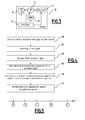
- microprocessor 21 executes software instructions from a program stored in the memory 22, the following steps are carried out, in reference to figure 4 :
- a step 100 the signal indicating successive measurements by the sensor 23 is delivered to the microprocessor 21.
- a step 101 the signal provided by the sensor is sampled and converted into numerical data representing successive values of the measured parameter.
- this numerical data is stored in the memory 22.
- a frequency representation of the signal is determined, for example using a Fourier transform (or a Laplace transform, or a Z-tranform, etc.).
- the spectrum thus determined includes peaks, each peak (or local maximum) corresponding to a frequency specific to each of the different parts of the bearing, such as the inner ring, the outer ring, the rolling elements, the cage, the lubricant.
- Each part such as rings, rolling elements, cage, etc., included by the bearing emits a vibration that can be connected to the frequency of rotation of the bearing.
- This vibration specific to the considered part of the bearing evolves with the wear of the considered part of the bearing and the wear of the bearing or damage to the functional surfaces of the contact ensuring proper operation of the bearing.
- the acquisition of play following wear or damage of the functional surfaces modifies the frequency position of that specific vibration in the vibrational spectrum, the amplitude or the phase relative to the speed of rotation.
- the lubricant also affects the vibrational spectrum of the bearing, since its purity, for example, may influence the form of the vibrational spectrum.
- This spectrum constitutes the signature of the bearing in its state corresponding to the considered time range.
- a step 104 one or more elements representative of the spectrum are compared relative to one or more corresponding so-called reference elements.
- These reference elements are determined based on a spectrum or one or more previously determined spectrums, called reference spectrums, or are calculated using theoretical formulas.
- These elements representative of the spectrum for example include a specific frequency of part of the bearing or the specific frequencies of several such parts, and/or the amplitude of one or more of said specific frequencies, and/or the energy of the spectrum in a predetermined frequency band.
- the frequency is a harmonic of the speed of rotation.
- these representative elements of the spectrum are compared to corresponding elements representative of a reference spectrum, for example determined from the new bearing.
- the reference spectrum may also be a spectrum obtained in a time range earlier than the currently considered range.
- the reference elements are for example obtained based on average spectrums or as a function of spectrums previously measured, for example on a new bearing, serving as a reference state or coming from a model of the progression of damage to the functional surfaces.
- a step 105 the presence or absence of a malfunction relative to the bearing is determined as a function of this comparison and, for example, minimum predetermined thresholds of the offset between the compared elements.
- the theoretical frequency is calculated for one part or each of several parts (rings, rolling elements, cage, lubricant, etc.) of the bearing.
- the vibrational signal emitted by the bearing is acquired.
- Filtering may be applied.
- the latter including a frequency component on the X axis and an amplitude component on the Y axis, is divided into several spectral bands (for example, the successive bands B1, B2, B3 and B4), each band being a zone in which a frequency subject to the monitoring is located.
- the sampling of the signal i.e., the acquisition of the corresponding frequency transform
- the sampling of the signal may be done by synchronizing the acquisition of the signal to the speed of rotation of the inner ring relative to the outer ring. This method requires a precise measurement of the variations of the relative speed of rotation.
- This processing makes it possible to eliminate the non-stationarity of the signal, which may move the specific frequencies sought, the specific frequencies of the parts of the bearing being harmonics of the speed of rotation.
- the monitored amplitude may be that of an acceleration, a speed or a movement. This choice depends primarily on the desired sensitivity for the measurement and the speed of rotation.
- the specific frequency of at least one part of the bearing is detected and a frequency shift of that specific frequency is thus identified in the obtained spectrum by comparison to the specific frequency of that same part in a reference spectrum or by comparison to the theoretical specific frequency of that same part given by the formulas.
- the presence of peeling on that part is determined based on a comparison.
- a maintenance operation may therefore be planned before the damage to the bearing becomes excessive or causes a breakdown on the transmission.
- the frequency peak specific to a part is detected following the search, in the obtained current spectrum, for the frequency peak closest to the frequency peak of said part in the reference spectrum (or the theoretical frequency), that peak being such that the difference between the amplitudes of the peak must further comply with certain conditions, for example have a standard below a given threshold.
- radiofrequency transmitter 24 which is suitable for transmitting it to a monitoring module 7 by radiofrequency channel.
- the transmission modalities are for example as follows: transmission every period with a fixed duration T, transmission each time data with a fixed volume V is available, and/or transmission when the value of a coefficient resulting from the comparison of step 105 reaches a fixed alert threshold, the coefficient being calculated by the processing module as a function of the value of the measurement data most recently stored.
- the alert threshold, the volume and/or the fixed duration T is stored in memory 22, for example.
- the set of sensors 23 for example includes a sensor suitable for measuring the temperature and/or the angular position of one ring relative to the other ring, etc.
- the set of sensors includes different types of sensors, for example a vibration sensor, temperature sensor, the measurements provided allow extensive coverage of the evolutions of defects within the bearing.
- Figure 5 illustrates the detectability of defects as a function of the methods and time. The moments A to E follow one another in that order over time.
- This defect may be detected as of moment B by ultrasound analysis (detection that ultrasound amplitude thresholds have been exceeded).
- this defect may be detected by multispectral analysis according to the invention as indicated in reference to steps 100-105.
- this defect may be detected by vibrational analysis (detection that vibration amplitude thresholds have been exceeded).
- This beginning of peeling in a bearing will cause, in a final stage as of moment E, a temperature increase, the debris thus released deteriorating the lubricant.
- the temperature increase may be detected by monitoring the temperatures.
- the ultrasound analysis consists of measuring the amplitudes of the time signal only.
- the components of the processing module 20 are integrated on microelectronics of the ASIC type.
- the radiofrequency transmitter 24 is replaced by a radiofrequency transceiver 24, capable of receiving information by radiofrequency channel.
- This information, processed by the microprocessor 21, is for example used to modify the processing of the measurements done by the processing module (no sampling, frequency of data transmissions, averaging parameters, etc.) and/or to modify the fixed alert threshold, volume and/or duration T that is stored in memory 22, for example.
- the processing module 20 is fixed on the inner face of the outer ring 11, i.e., on the face of the outer ring across from the inner ring 12.
- the module 20 is fixed on the inner face of the inner ring 12, i.e., on the face of the outer ring across from the element around which the inner ring 12 is fixed.
- the module 20 is fixed on the outer face of the inner ring 12, i.e., on the face of the inner ring across from the outer ring 11.
- the transmission 1 further includes the monitoring module 7 fixed on the outside of the housing 6.
- the monitoring module 7 comprises a radiofrequency receiver capable of receiving the radiofrequency data emitted by each of the bearings 2 similar to the bearing 10 described above.
- the monitoring module 7 further comprises a memory and is suitable for storing the radiofrequency data matched with an identifier of the bearing from which it was emitted, and optionally matched with dating data for example representative of the time of receipt of the data by the monitoring module.
- the monitoring module 7 is suitable for performing processing operations on that data. For example, the monitoring module 7 performs averaging operations for data emitted by a bearing. For example, the monitoring module 7 is suitable for combining data emitted by separate bearings, so as to identify or characterize malfunctions as a function of that combined data.
- the system for example averages the amplitudes of the signal relative to a frequency division defined from specific frequencies of the parts of the bearing.
- the temperature is also averaged and recorded. As previously illustrated, it serves as a final alert threshold in the event the other indicators have not detected a defect.
- the monitoring module 7 includes transmission means, for example wired, suitable for transmitting the processed data to centralization equipment.
- the processing module 20 then uses the radiofrequency transmitter 24 to send the digital data resulting from step 100, 101, 102, 103-or 104 to another processing module, which in turn performs all or some of the subsequent steps.
- This other processing module is, depending on the embodiments, remote from the bearing; for example, it is integrated into the monitoring module 7. In one embodiment, it may be integrated into the bearing, but located somewhere other than the processing module 20.
- the invention thus makes it possible to monitor the elements of the transmission and their operating conditions, and to identify signs of malfunction. It is thus possible to detect, as early as possible and more precisely than in the systems of the prior art, the occurrence of cracks on gear teeth and deteriorations of bearings, and to take the necessary corrective actions.
- BPFI Ball Pass Frequency of the Inner Ring, which is the frequency at which the rolling elements 14 pass in the rolling path of the inner ring
- BPFI z 2 ⁇ 1 + D w d m ⁇ cos ⁇
- z is the number of rolling elements in each row of rolling elements
- D w is the diameter of a rolling element 14
- d m is the diameter of the circle traveled by a rolling element
- ⁇ is the contact angle of the rolling elements on the path.
- the shifts of this BPFI frequency are representative of damage affecting the rolling path of the inner ring.
- BPFO Ball Pass Frequency of the Outer Ring, which is the frequency at which the rolling elements 14 pass in the rolling path of the outer ring
- BPFO z 2 ⁇ 1 - D w d m ⁇ cos ⁇ .
- the shifts of this BPFO frequency are representative of damage affecting the rolling path of the outer ring (fragments or slits, for example).
- BSF Ball Spin Frequency, which is the frequency at which the rolling elements 14 rotate around themselves in the bearing
- the shifts of this BSF frequency are representative of damage affecting a rolling element.
- Frequency which is the frequency at which the cage, containing the rolling elements 14, rotates
- FTF 1 2 ⁇ 1 - D w d m ⁇ cos ⁇ .
Landscapes
- Engineering & Computer Science (AREA)
- General Engineering & Computer Science (AREA)
- Physics & Mathematics (AREA)
- Mechanical Engineering (AREA)
- General Physics & Mathematics (AREA)
- Acoustics & Sound (AREA)
- Testing Of Devices, Machine Parts, Or Other Structures Thereof (AREA)
- Rolling Contact Bearings (AREA)
Abstract
- a first module (20) including at least one set of sensor(s) suitable for performing successive measurements of at least one parameter representative of the vibrations within the bearing; and
- a second module (20) suitable for determining a frequency representation of the signal corresponding to the successive measurements, and for obtaining a set of elements(s) representative of said frequency representation based on that frequency representation, so as to compare at least one representative element of said set with a corresponding reference element and identify a malfunction based on that comparison (10).
Description
- The present invention relates to a bearing including an inner ring and an outer ring and rolling bodies positioned between said rings, one of said rings being rotary and the other not.
- Such bearings are for example used in various equipments, in particular transmissions, for example helicopter transmissions, as described in document
EP0172104 . - In such a transmission, it is necessary to monitor the state and operating conditions of the component elements thereof, in particular elements for which the bearing is the support. The known monitoring elements for such a transmission generally use an array of sensors outside the transmission, and the reliability is not very satisfactory.
- The present invention aims in particular to improve the monitoring of such equipment.
- To that end, according to a first aspect, the invention proposes a bearing of the aforementioned type, characterized in that it further includes:
- a first module including at least one set of sensor(s) suitable for performing successive measurements of at least one parameter representative of the vibrations within the bearing; and
- a second module suitable for determining a frequency representation of the signal corresponding to the successive measurements, and for obtaining a set of elements(s) representative of said frequency representation as a function of that frequency representation, so as to compare at least one representative element of said set with a corresponding reference element and identify a malfunction as a function of that comparison.
- Such a bearing makes it possible to provide information on the local and actual operating conditions of the bearings.
- In embodiments, the bearing according to the invention further includes one or more of the following features:
- a set of sensor(s) is suitable for performing successive measurements of at least one parameter representative of low-frequency, medium-frequency, high-frequency and/or ultrasonic frequency vibrations, within the bearing;
- the first module is secured to one of said rings;
- the second module is suitable for comparing said at least one element representative of said frequency representation with a corresponding reference element;
- said set of representative element(s) includes at least one frequency corresponding to a peak of the frequency representation, and/or the amplitude of said peak, and/or the spectral energy in a predetermined bandwidth of the frequency representation;
- the time separating two successive time samples considered for the frequency transform used to determine the frequency representation depends on the relative speed of rotation between the two inner and outer rings;
- the second module is secured to one of said rings;
- the bearing includes radiofrequency communication module suitable for emitting data depending on at least said representative element;
- the bearing further includes power supply means for at least the first module;
- the set of sensor(s) is further suitable for measuring the temperature and/or a relative angular movement between the inner and outer rings;
- the first module is a system on chip.
- According to a second aspect, the present invention proposes a housing including a set of bearing(s) according to the first aspect of the invention, further including a radiofrequency receiving module and a multiplex transmission module, said housing being suitable for receiving, by means of the radiofrequency receiving module, the data emitted by each bearing of the bearing assembly, processing the data and sending said process data to a recipient outside said housing, using the multiplex transmission module.
- According to a third aspect, the present invention proposes a method for determining a malfunction in a bearing including at least an inner ring, an outer ring, and rolling bodies positioned between said inner and outer rings, one of said rings being rotary and the other being not rotary, said method comprising the following steps:
- performing successive measurements of a parameter representative of the vibrations within the bearing;
- determining a frequency representation of the signal corresponding to the successive measurements, and obtaining a set of elements(s) representative of said frequency representation as a function of said frequency representation;
- comparing at least one element representative of said assembly with a corresponding reference element so as to identify a malfunction as a function of said comparison.
- According to a fourth aspect, the present invention proposes a computer program intended for a module for determining a malfunction in a bearing including at least an inner ring, an outer ring, and rolling bodies positioned between said inner and outer rings, one of said rings being rotary and the other being not rotary, said computer program being characterized in that it includes software instructions which, when run on a computer of said module for determining a malfunction in a bearing, carry out the steps of a method according to the third aspect of the invention.
- These features and advantages of the invention will appear upon reading the following description, provided solely as an example, and done in reference to the appended drawings, in which:
-
figure 1 shows a cross-sectional view of a helicopter transmission; -
figure 2 is a view of a bearing in one embodiment of the invention; -
figure 3 is a summary view of a processing module of the bearing in one embodiment of the invention; -
figure 4 is a flowchart of steps carried out by the processing module offigure 3 in one embodiment of the invention; -
figure 5 illustrates the detectability of defects as a function of the methods and time. -
Figure 1 shows a cross-sectional view of a helicopter transmission 1. This transmission 1 is suitable for transmitting rotational movement between the primary shaft 4, which is the shaft of the engine, and asecondary shaft 5, which is the rotor of the helicopter, according to several transmission ratios. It comprises an outer housing 6 which includes, aside from the primary and secondary shafts,several bearings 2 and several gears 3. - In one embodiment of the invention, each of these
bearings 2 is similar to themechanical bearing 10 described below in reference tofigures 2 and3 . - In reference to
figure 2 , a mechanical bearing 10 in one embodiment of the invention includes two coaxial rings: anouter ring 11 and aninner ring 12. - Between these
coaxial rings - In a known manner, a
bearing 10 optimizes the friction between two parts and procures support for one of the two parts, which is rotating. - One of these parts (not shown) is secured to the
inner ring 12. This is for example a rotating shaft positioned in thehousing 13 circumscribed by theinner ring 12. Theinner ring 12 is for example mounted tightened on the rotating shaft. In the case of the transmission 1, this shaft is for example the primary shaft 4. - The other part is fastened to the
outer ring 13. For example, the other part is a part of the housing outside the transmission 1, and is stationary relative to the rotating shaft. - It will be noted that in
other bearings 10 according to the invention, it is the outer ring that is tightly fixed to a rotating part, while the inner ring is secured to the stationary part. - According to the invention, a
processing module 20 is fixed on one of the rings. For example, theprocessing module 20 is integrated into a fixed housing on a ring of the bearing, by screwing or crimping. In another example, a form is created in a ring of the bearing, that form serving as a support for theprocessing module 20. - As shown in
figure 2 , in the considered case, theprocessing module 20 is fixed on the outer surface of theouter ring 11. - The
processing module 20 includes amicroprocessor 21, amemory 22, asensor 23 suitable for measuring one or more parameters, aradiofrequency transmitter 24, and apower supply module 25. - The
power supply module 25 is suitable for supplying electricity to the components of theprocessing module 20, the operation of which requires such electricity. Thus, it provides electricity in particular to themicroprocessor 21, theradiofrequency transceiver 24, and optionally thesensor 23. - In one embodiment, the
sensor 23 is a sensor suitable for measuring at least one parameter representative of vibrations along one axis (for example, the radial axis relative to the rings of the bearing), or along two axes or three axes. Such a sensor for example comprises one or more accelerometers. - In one embodiment, the
sensor 23 suitable for measuring at least one parameter representative of the vibrations occurring in the entire frequency range, i.e., a low frequency (below 10 Hz), medium frequency (10-1,000 Hz), high frequency (above 1,000 Hz), and ultrasonic frequency (20-2,000 kHz). - In another embodiment, the
sensor 23 is suitable for measuring at least one parameter representative of the vibrations occurring in part of that frequency range. - In one embodiment, the
sensor 23 is suitable for delivering a signal, for example analog, to themicroprocessor 21, indicating the successive measurements of the parameter taken by thesensor 23. - After the
microprocessor 21 executes software instructions from a program stored in thememory 22, the following steps are carried out, in reference tofigure 4 : - In a
step 100, the signal indicating successive measurements by thesensor 23 is delivered to themicroprocessor 21. - In a
step 101, the signal provided by the sensor is sampled and converted into numerical data representing successive values of the measured parameter. - In a
step 102, this numerical data is stored in thememory 22. - In a
step 103, from this successive numerical temporal data over a time range with length T0, a frequency representation of the signal is determined, for example using a Fourier transform (or a Laplace transform, or a Z-tranform, etc.). - The spectrum thus determined includes peaks, each peak (or local maximum) corresponding to a frequency specific to each of the different parts of the bearing, such as the inner ring, the outer ring, the rolling elements, the cage, the lubricant.
- Each part such as rings, rolling elements, cage, etc., included by the bearing emits a vibration that can be connected to the frequency of rotation of the bearing. This vibration specific to the considered part of the bearing evolves with the wear of the considered part of the bearing and the wear of the bearing or damage to the functional surfaces of the contact ensuring proper operation of the bearing. The acquisition of play following wear or damage of the functional surfaces modifies the frequency position of that specific vibration in the vibrational spectrum, the amplitude or the phase relative to the speed of rotation.
- The lubricant also affects the vibrational spectrum of the bearing, since its purity, for example, may influence the form of the vibrational spectrum.
- This spectrum constitutes the signature of the bearing in its state corresponding to the considered time range.
- In a
step 104, one or more elements representative of the spectrum are compared relative to one or more corresponding so-called reference elements. These reference elements are determined based on a spectrum or one or more previously determined spectrums, called reference spectrums, or are calculated using theoretical formulas. - These elements representative of the spectrum for example include a specific frequency of part of the bearing or the specific frequencies of several such parts, and/or the amplitude of one or more of said specific frequencies, and/or the energy of the spectrum in a predetermined frequency band.
- These representative frequencies depend on the geometric characteristics of the bearing, as well as its type (ball bearing, roller bearing, etc.).
- The theoretical calculation formulas are well known by those skilled in the art and will be recalled below. The frequency is a harmonic of the speed of rotation.
- In one embodiment, these representative elements of the spectrum are compared to corresponding elements representative of a reference spectrum, for example determined from the new bearing.
- The reference spectrum may also be a spectrum obtained in a time range earlier than the currently considered range. In one embodiment, the reference elements are for example obtained based on average spectrums or as a function of spectrums previously measured, for example on a new bearing, serving as a reference state or coming from a model of the progression of damage to the functional surfaces.
- In a
step 105, the presence or absence of a malfunction relative to the bearing is determined as a function of this comparison and, for example, minimum predetermined thresholds of the offset between the compared elements. - For example, let us consider the case of a bearing whereof the rings rotate at two different speeds of rotation.
- The theoretical frequency is calculated for one part or each of several parts (rings, rolling elements, cage, lubricant, etc.) of the bearing.
- This calculation makes it possible to define the theoretical frequency of each considered part of the bearing, and therefore its position in the spectrum.
- One of these frequencies is for example obtained using the following formula:
- ■

- The vibrational signal emitted by the bearing is acquired.
- Filtering may be applied.
- The current spectrum of the bearing is obtained.
- The latter, including a frequency component on the X axis and an amplitude component on the Y axis, is divided into several spectral bands (for example, the successive bands B1, B2, B3 and B4), each band being a zone in which a frequency subject to the monitoring is located.
- If the speeds of rotation of the bearing are not fixed, the sampling of the signal, i.e., the acquisition of the corresponding frequency transform, may be done by synchronizing the acquisition of the signal to the speed of rotation of the inner ring relative to the outer ring. This method requires a precise measurement of the variations of the relative speed of rotation.
- This processing makes it possible to eliminate the non-stationarity of the signal, which may move the specific frequencies sought, the specific frequencies of the parts of the bearing being harmonics of the speed of rotation.
- In each band B1 to B4, the following processing is for example applied:
- i/ Identification of the theoretical specific frequencies and associated harmonics (multiples of the specific frequency) in each band. The amplitude of the vibrational spectrum of each of these frequencies is compared to its amplitude for a new bearing.
- ii/ In each spectral band (B1, B2, B3, B4), calculating an indicator relative to the form of the signal (kurtosis, average of the amplitudes, peak-to-peak ratio). The level of this indicator is compared to that of the new bearing so as to determine its level of damage.
- The monitored amplitude may be that of an acceleration, a speed or a movement. This choice depends primarily on the desired sensitivity for the measurement and the speed of rotation.
- For example, in one embodiment, the specific frequency of at least one part of the bearing is detected and a frequency shift of that specific frequency is thus identified in the obtained spectrum by comparison to the specific frequency of that same part in a reference spectrum or by comparison to the theoretical specific frequency of that same part given by the formulas. The presence of peeling on that part is determined based on a comparison. A maintenance operation may therefore be planned before the damage to the bearing becomes excessive or causes a breakdown on the transmission.
- In one embodiment, the frequency peak specific to a part is detected following the search, in the obtained current spectrum, for the frequency peak closest to the frequency peak of said part in the reference spectrum (or the theoretical frequency), that peak being such that the difference between the amplitudes of the peak must further comply with certain conditions, for example have a standard below a given threshold.
- Then, information resulting from this processing is provided to the
radiofrequency transmitter 24, which is suitable for transmitting it to amonitoring module 7 by radiofrequency channel. - The transmission modalities are for example as follows: transmission every period with a fixed duration T, transmission each time data with a fixed volume V is available, and/or transmission when the value of a coefficient resulting from the comparison of
step 105 reaches a fixed alert threshold, the coefficient being calculated by the processing module as a function of the value of the measurement data most recently stored. The alert threshold, the volume and/or the fixed duration T is stored inmemory 22, for example. - In one embodiment, the set of
sensors 23 for example includes a sensor suitable for measuring the temperature and/or the angular position of one ring relative to the other ring, etc. - When the set of sensors includes different types of sensors, for example a vibration sensor, temperature sensor, the measurements provided allow extensive coverage of the evolutions of defects within the bearing.
-
Figure 5 illustrates the detectability of defects as a function of the methods and time. The moments A to E follow one another in that order over time. - Let us consider that at moment A, the beginning of peeling has occurred.
- This defect may be detected as of moment B by ultrasound analysis (detection that ultrasound amplitude thresholds have been exceeded).
- As of moment C, this defect may be detected by multispectral analysis according to the invention as indicated in reference to steps 100-105.
- As of moment D, this defect may be detected by vibrational analysis (detection that vibration amplitude thresholds have been exceeded).
- This beginning of peeling in a bearing will cause, in a final stage as of moment E, a temperature increase, the debris thus released deteriorating the lubricant. The temperature increase may be detected by monitoring the temperatures.
- The ultrasound analysis consists of measuring the amplitudes of the time signal only.
- In one embodiment, the components of the
processing module 20 are integrated on microelectronics of the ASIC type. - In one embodiment, the
radiofrequency transmitter 24 is replaced by aradiofrequency transceiver 24, capable of receiving information by radiofrequency channel. This information, processed by themicroprocessor 21, is for example used to modify the processing of the measurements done by the processing module (no sampling, frequency of data transmissions, averaging parameters, etc.) and/or to modify the fixed alert threshold, volume and/or duration T that is stored inmemory 22, for example. - It will be noted that in another embodiment, the
processing module 20 is fixed on the inner face of theouter ring 11, i.e., on the face of the outer ring across from theinner ring 12. In another embodiment, themodule 20 is fixed on the inner face of theinner ring 12, i.e., on the face of the outer ring across from the element around which theinner ring 12 is fixed. In another embodiment, themodule 20 is fixed on the outer face of theinner ring 12, i.e., on the face of the inner ring across from theouter ring 11. - In one embodiment of the invention, the transmission 1 further includes the
monitoring module 7 fixed on the outside of the housing 6. - The
monitoring module 7 comprises a radiofrequency receiver capable of receiving the radiofrequency data emitted by each of thebearings 2 similar to thebearing 10 described above. - The
monitoring module 7 further comprises a memory and is suitable for storing the radiofrequency data matched with an identifier of the bearing from which it was emitted, and optionally matched with dating data for example representative of the time of receipt of the data by the monitoring module. - In one embodiment, the
monitoring module 7 is suitable for performing processing operations on that data. For example, themonitoring module 7 performs averaging operations for data emitted by a bearing. For example, themonitoring module 7 is suitable for combining data emitted by separate bearings, so as to identify or characterize malfunctions as a function of that combined data. - The system for example averages the amplitudes of the signal relative to a frequency division defined from specific frequencies of the parts of the bearing. The temperature is also averaged and recorded. As previously illustrated, it serves as a final alert threshold in the event the other indicators have not detected a defect.
- In one embodiment, the
monitoring module 7 includes transmission means, for example wired, suitable for transmitting the processed data to centralization equipment. - In one embodiment, only part of the
processing operations 100 to 105 are performed in theprocessing module 20 secured to the ring. In such a case, theprocessing module 20 then uses theradiofrequency transmitter 24 to send the digital data resulting fromstep monitoring module 7. In one embodiment, it may be integrated into the bearing, but located somewhere other than theprocessing module 20. - The invention thus makes it possible to monitor the elements of the transmission and their operating conditions, and to identify signs of malfunction. It is thus possible to detect, as early as possible and more precisely than in the systems of the prior art, the occurrence of cracks on gear teeth and deteriorations of bearings, and to take the necessary corrective actions.
- It also makes it possible to detect, as early as possible and more precisely than the systems of the prior art, for example, excessive temperature variations, etc., and to take the necessary corrective actions.
- In one embodiment, the
power supply module 25 includes a fuel cell, a battery integrated into the system on chip, and/or is suitable for receiving electricity resulting from the conversion of the mechanical energy generated by the ball bearing, as described below. - Several theoretical formulas for determining specific frequencies are provided below, where it is considered that only one ring rotates.
- The passage frequency of a rolling element of the inner ring (BPFI, Ball Pass Frequency of the Inner Ring, which is the frequency at which the rolling elements 14 pass in the rolling path of the inner ring), is:

where
z is the number of rolling elements in each row of rolling elements;
Dw is the diameter of a rolling element 14;
dm is the diameter of the circle traveled by a rolling element;
α is the contact angle of the rolling elements on the path. - The shifts of this BPFI frequency are representative of damage affecting the rolling path of the inner ring.
- The theoretical formula of the passage frequency of a rolling element of the outer ring (BPFO, Ball Pass Frequency of the Outer Ring, which is the frequency at which the rolling elements 14 pass in the rolling path of the outer ring), is:

- The shifts of this BPFO frequency are representative of damage affecting the rolling path of the outer ring (fragments or slits, for example).
- The theoretical formula for the frequency of rotation of the rolling elements rolling around themselves (BSF, Ball Spin Frequency, which is the frequency at which the rolling elements 14 rotate around themselves in the bearing), is:

- The shifts of this BSF frequency are representative of damage affecting a rolling element.
- The theoretical formula of the Fundamental Train Frequency (FTF, which is the frequency at which the cage, containing the rolling elements 14, rotates), is

- The shifts of this FTF frequency are representative of damage affecting the cage.
Claims (20)
- A bearing (10) including an inner ring (12), an outer ring (11), and rolling bodies positioned between said inner and outer rings, one of said rings being rotary and the other not, said bearing being characterized in that it further includes:- a first module (20) including at least one set of sensor(s) suitable for performing successive measurements of at least one parameter representative of the vibrations within the bearing; and- a second module (20) suitable for determining a frequency representation of the signal corresponding to the successive measurements, and for obtaining a set of elements(s) representative of said frequency representation as a function of that frequency representation, so as to compare at least one representative element of said set with a corresponding reference element and identify a malfunction as a function of that comparison (10).
- The bearing (10) according to claim 1, wherein a set of sensor(s) is suitable for performing successive measurements of at least one parameter representative of low-frequency, medium-frequency, high-frequency and/or ultrasonic frequency vibrations, within the bearing.
- The bearing (10) according to claim 1 or 2, wherein the first module (20) is secured to one of said rings.
- The bearing (10) according to one of the preceding claims, wherein said second module (20) is suitable for comparing said at least one element representative of said frequency representation with a corresponding reference element.
- The bearing (10) according to one of the preceding claims, wherein said set of representative element(s) includes at least one frequency corresponding to a peak of the frequency representation, and/or the amplitude of said peak, and/or the spectral energy in a predetermined bandwidth of the frequency representation.
- The bearing (10) according to one of the preceding claims, wherein the time separating two successive time samples considered for the frequency transform used to determine the frequency representation depends on the relative speed of rotation between the two inner (12) and outer (11) rings.
- The bearing (10) according to one of the preceding claims, wherein the second module (20) is secured to one of said rings (11, 12).
- The bearing (10) according to one of the preceding claims, including a radiofrequency communication module (24) suitable for emitting data depending on at least said representative element.
- The bearing (10) according to one of the preceding claims, further including power supply means (25) for at least the first module (20).
- The bearing (10) according to one of the preceding claims, wherein the set of sensor(s) (23) is further suitable for measuring the temperature and/or a relative angular movement between the inner and outer rings.
- The bearing according to one of the preceding claims, wherein the first module is a system on chip.
- A housing (1) including a set of bearing(s) (2, 10) according to one of the preceding claims, further including a radiofrequency receiving module (7) and a multiplex transmission module (7), said housing being suitable for receiving, by means of the radiofrequency receiving module, the data emitted by each bearing of the bearing assembly, processing the data and sending said process data to a recipient outside said housing, using the multiplex transmission module.
- A method for determining a malfunction in a bearing (10) including at least an inner ring (12), an outer ring (11), and rolling bodies positioned between said inner and outer rings, one of said rings being rotary and the other not, said method including the following steps:- performing successive measurements of a parameter representative of the vibrations within the bearing;- determining a frequency representation of the signal corresponding to the successive measurements, and obtaining a set of elements(s) representative of said frequency representation as a function of on said frequency representation;- comparing at least one element representative of said assembly with a corresponding reference element so as to identify a malfunction as a function of said comparison.
- The method according to claim 13, wherein the at least one measured parameter is representative of the low-frequency, medium-frequency, high-frequency and/or ultrasonic frequency vibrations, within the bearing.
- The method according to claim 13 or 14, wherein the bearing (10) includes a first module (20) secured to one of said rings and including at least one set of sensor(s) (23) suitable for performing said successive measurements.
- The method according to claim 15, wherein the bearing (10) includes a second module (20) suitable for determining said frequency representation of the signal, and obtaining a set of element(s) representative of said frequency representation as a function of said frequency representation.
- The method according to claim 16, wherein the second module (20) is further suitable for comparing at least one element representative of said set with a corresponding reference element in order to identify a malfunction based on said comparison.
- The method according to one of claims 13 to 17, wherein said set of representative element(s) includes at least one frequency corresponding to a peak of the frequency representation, and/or the amplitude of said peak, and/or the spectral energy in a predetermined bandwidth of the frequency representation.
- The method according to one of claims 13 to 18, wherein the time separating two successive considered time samples for the frequency transform used to determine the frequency representation is a function of the relative speed of rotation between the two inner (12) and outer (11) rings.
- A computer program intended for a module (20) for determining a malfunction in a bearing (10) including at least an inner ring (12), an outer ring (11), and rolling bodies positioned between said inner and outer rings, one of said rings being rotary and the other being not rotary, said computer program being characterized in that it includes software instructions which, when run on a computer (21) of said module for determining a malfunction in a bearing, carry out the steps of a method according to one of claims 13 to 19.
Applications Claiming Priority (1)
| Application Number | Priority Date | Filing Date | Title |
|---|---|---|---|
| FR1260743A FR2998019B1 (en) | 2012-11-12 | 2012-11-12 | BEARING, HOUSING COMPRISING A BEARING ASSEMBLY (S), METHOD AND COMPUTER PROGRAM |
Publications (2)
| Publication Number | Publication Date |
|---|---|
| EP2730898A1 true EP2730898A1 (en) | 2014-05-14 |
| EP2730898B1 EP2730898B1 (en) | 2023-04-05 |
Family
ID=47505151
Family Applications (1)
| Application Number | Title | Priority Date | Filing Date |
|---|---|---|---|
| EP13192403.7A Active EP2730898B1 (en) | 2012-11-12 | 2013-11-12 | Bearing, housing including a set of bearings, associated method and computer program |
Country Status (3)
| Country | Link |
|---|---|
| US (1) | US9464671B2 (en) |
| EP (1) | EP2730898B1 (en) |
| FR (1) | FR2998019B1 (en) |
Cited By (4)
| Publication number | Priority date | Publication date | Assignee | Title |
|---|---|---|---|---|
| FR3041760A1 (en) * | 2015-09-30 | 2017-03-31 | Ntn-Snr Roulements | METHOD FOR DETECTING A TRANSIENT ROTATION FAILURE OF A ROTATING MEMBER |
| CN107063678A (en) * | 2016-10-27 | 2017-08-18 | 大连理工大学 | It is a kind of from base standard gear and its measuring method |
| FR3051043A1 (en) * | 2016-05-09 | 2017-11-10 | Ntn-Snr Roulements | METHOD FOR DETECTING A ROTATION STATE OF A MECHANICAL ASSEMBLY COMPRISING A ROTATING MEMBER |
| CN111896257A (en) * | 2020-07-15 | 2020-11-06 | 江门职业技术学院 | Rolling bearing fault diagnosis method and system |
Families Citing this family (10)
| Publication number | Priority date | Publication date | Assignee | Title |
|---|---|---|---|---|
| JP6205803B2 (en) * | 2013-04-05 | 2017-10-04 | 日本精工株式会社 | Test equipment for radial rolling bearings |
| DE102015202130A1 (en) * | 2015-02-06 | 2016-08-11 | Schaeffler Technologies AG & Co. KG | Construction kit for warehouse and warehouse arrangement |
| US10788395B2 (en) * | 2017-02-10 | 2020-09-29 | Aktiebolaget Skf | Method and device of processing of vibration sensor signals |
| JP6856403B2 (en) * | 2017-02-24 | 2021-04-07 | 本田技研工業株式会社 | Squeeze film damper bearing device |
| US10794173B2 (en) * | 2017-04-13 | 2020-10-06 | Weatherford Technology Holdings, Llc | Bearing fault detection for surface pumping units |
| CN109784305B (en) * | 2019-01-29 | 2020-12-08 | 石家庄铁道大学 | A Dictionary Construction Method of Lapalce Wavelet-Based Sparse Representation Based on Waveform Shock Matching |
| FR3104716B1 (en) * | 2019-12-13 | 2021-12-17 | Centre Techn Ind Mecanique | Method for detecting angular offset between a rolling ring and a rotating hollow body in engagement with each other |
| CN113588269A (en) * | 2021-09-06 | 2021-11-02 | 四川安沃德轨道装备科技有限公司 | Bearing service state monitoring method and system |
| IT202200019032A1 (en) * | 2022-09-16 | 2024-03-16 | Mecaer Aviation Group S P A | AIRCRAFT SAFETY SYSTEM AND RELATED MONITORING SYSTEM |
| DE102023202324A1 (en) * | 2023-03-15 | 2024-09-19 | Aktiebolaget Skf | Apparatus and method for determining an envelope of a signal |
Citations (7)
| Publication number | Priority date | Publication date | Assignee | Title |
|---|---|---|---|---|
| EP0172104A1 (en) | 1984-08-06 | 1986-02-19 | AEROSPATIALE Société Nationale Industrielle | Main transmission gear box for a two-engine helicopter |
| US20020139191A1 (en) * | 2001-03-29 | 2002-10-03 | Hedeen Robert A. | System and method for conditioned-based monitoring of a bearing assembly |
| US20050119840A1 (en) * | 2003-01-10 | 2005-06-02 | Rolls-Royce Plc | Bearing anomaly detection and location |
| EP1548419A1 (en) * | 2002-08-30 | 2005-06-29 | NSK Ltd. | Method and device for monitoring status of mechanical equipment and abnormality diagnosing device |
| US20080234964A1 (en) * | 2004-09-13 | 2008-09-25 | Nsk Ltd. | Abnormality Diagnosing Apparatus and Abnormality Diagnosing Method |
| FR2918172A1 (en) * | 2007-06-27 | 2009-01-02 | Univ Reims Champagne Ardenne | DEVICE AND METHOD FOR MONITORING THE VIBRATION CONDITION OF A ROTATING MACHINE. |
| DE102008021360A1 (en) * | 2008-04-29 | 2009-11-05 | Siemens Aktiengesellschaft | Method and device for detecting bearing damage |
Family Cites Families (8)
| Publication number | Priority date | Publication date | Assignee | Title |
|---|---|---|---|---|
| FR2796679B1 (en) * | 1999-07-23 | 2001-08-24 | Skf France | INSTRUMENT BEARING |
| TW579424B (en) * | 2001-07-09 | 2004-03-11 | Shell Int Research | Vibration analysis for predictive maintenance in machinery |
| JP4753654B2 (en) * | 2005-08-03 | 2011-08-24 | Ntn株式会社 | Evaluation method for rolling bearing parts |
| US20070262875A1 (en) * | 2006-05-12 | 2007-11-15 | El-Ibiary Yehia M | RF tag for a mechanical component |
| DE102010024850A1 (en) * | 2010-06-23 | 2011-12-29 | Deutsches Zentrum für Luft- und Raumfahrt e.V. | Method for determining rotation speed of e.g. rotatable shaft that is rotated opposite to e.g. outer ring in tachogenerator, involves determining rotation speed based on detected signal patterns of output signal at piezoresistive transducer |
| JP5442553B2 (en) * | 2010-07-21 | 2014-03-12 | 日立建機株式会社 | Bearing damage detection method |
| CN102412858B (en) * | 2011-11-04 | 2016-08-24 | 南京中兴软件有限责任公司 | The method of RF transceiver, terminal and terminal received signals |
| CN102709668B (en) * | 2012-05-17 | 2014-08-13 | 华为技术有限公司 | Mounting bracket |
-
2012
- 2012-11-12 FR FR1260743A patent/FR2998019B1/en not_active Expired - Fee Related
-
2013
- 2013-11-12 EP EP13192403.7A patent/EP2730898B1/en active Active
- 2013-11-12 US US14/078,320 patent/US9464671B2/en not_active Expired - Fee Related
Patent Citations (7)
| Publication number | Priority date | Publication date | Assignee | Title |
|---|---|---|---|---|
| EP0172104A1 (en) | 1984-08-06 | 1986-02-19 | AEROSPATIALE Société Nationale Industrielle | Main transmission gear box for a two-engine helicopter |
| US20020139191A1 (en) * | 2001-03-29 | 2002-10-03 | Hedeen Robert A. | System and method for conditioned-based monitoring of a bearing assembly |
| EP1548419A1 (en) * | 2002-08-30 | 2005-06-29 | NSK Ltd. | Method and device for monitoring status of mechanical equipment and abnormality diagnosing device |
| US20050119840A1 (en) * | 2003-01-10 | 2005-06-02 | Rolls-Royce Plc | Bearing anomaly detection and location |
| US20080234964A1 (en) * | 2004-09-13 | 2008-09-25 | Nsk Ltd. | Abnormality Diagnosing Apparatus and Abnormality Diagnosing Method |
| FR2918172A1 (en) * | 2007-06-27 | 2009-01-02 | Univ Reims Champagne Ardenne | DEVICE AND METHOD FOR MONITORING THE VIBRATION CONDITION OF A ROTATING MACHINE. |
| DE102008021360A1 (en) * | 2008-04-29 | 2009-11-05 | Siemens Aktiengesellschaft | Method and device for detecting bearing damage |
Cited By (5)
| Publication number | Priority date | Publication date | Assignee | Title |
|---|---|---|---|---|
| FR3041760A1 (en) * | 2015-09-30 | 2017-03-31 | Ntn-Snr Roulements | METHOD FOR DETECTING A TRANSIENT ROTATION FAILURE OF A ROTATING MEMBER |
| FR3051043A1 (en) * | 2016-05-09 | 2017-11-10 | Ntn-Snr Roulements | METHOD FOR DETECTING A ROTATION STATE OF A MECHANICAL ASSEMBLY COMPRISING A ROTATING MEMBER |
| CN107063678A (en) * | 2016-10-27 | 2017-08-18 | 大连理工大学 | It is a kind of from base standard gear and its measuring method |
| CN111896257A (en) * | 2020-07-15 | 2020-11-06 | 江门职业技术学院 | Rolling bearing fault diagnosis method and system |
| CN111896257B (en) * | 2020-07-15 | 2022-03-18 | 江门职业技术学院 | A kind of rolling bearing fault diagnosis method and system |
Also Published As
| Publication number | Publication date |
|---|---|
| EP2730898B1 (en) | 2023-04-05 |
| FR2998019A1 (en) | 2014-05-16 |
| FR2998019B1 (en) | 2016-07-22 |
| US9464671B2 (en) | 2016-10-11 |
| US20140169715A1 (en) | 2014-06-19 |
Similar Documents
| Publication | Publication Date | Title |
|---|---|---|
| EP2730898B1 (en) | Bearing, housing including a set of bearings, associated method and computer program | |
| EP2522977B1 (en) | Abnormality diagnosis device for rolling bearing, wind power generator, and abnormality diagnosis system | |
| US10519935B2 (en) | Condition monitoring system and wind power generation system using the same | |
| US10360737B2 (en) | System and method for improved drive system diagnostics | |
| US10337958B2 (en) | Bearing device vibration analysis method, bearing device vibration analyzer, and rolling bearing condition monitoring system | |
| JP7027782B2 (en) | Rolling bearing abnormality diagnostic device | |
| CN106481785B (en) | A state monitoring method and unit for bearings | |
| US8364424B2 (en) | System and method for monitoring a wind turbine gearbox | |
| US9459179B2 (en) | Method and device for monitoring a drive train of a wind power plant | |
| US11105712B2 (en) | Integrated vibe/ODM fusion and trending analysis for prognostic health management of engine bearing | |
| CN108700492B (en) | Abnormality diagnosis device and abnormality diagnosis method | |
| EP3842780B1 (en) | Method and device for diagnosing abnormality in rolling bearing | |
| JP2018179735A (en) | Method and apparatus for diagnosing abnormality of rotating parts | |
| CN103140672A (en) | Method for performing condition monitoring in a wind power plant | |
| US10975849B2 (en) | Condition monitoring system and wind turbine including the same | |
| CN107429818A (en) | The measuring system and measuring method of the variable on planet carrier for detecting epicyclic transmission mechanism | |
| JP2022185599A (en) | Abnormality diagnosis method and abnormality diagnosis device for rolling bearing | |
| WO2018088564A1 (en) | Bearing abnormality diagnostic method and diagnostic system | |
| JP6639266B2 (en) | Abnormality diagnosis device and abnormality diagnosis method | |
| JP2016070767A (en) | Automatic vibration diagnostic equipment for rotating machinery | |
| JP2017207435A (en) | Abnormality diagnostic method | |
| JP2017150884A (en) | Abnormality diagnosis device and abnormality diagnosis method | |
| CN119064003A (en) | System and associated method for monitoring rolling element bearings | |
| JP6561720B2 (en) | Bearing evaluation device | |
| Kramti et al. | Advanced diagnostic methods for bearings in wind tur-bine: Indicators analysis and hyperparameters automa-tion |
Legal Events
| Date | Code | Title | Description |
|---|---|---|---|
| PUAI | Public reference made under article 153(3) epc to a published international application that has entered the european phase |
Free format text: ORIGINAL CODE: 0009012 |
|
| 17P | Request for examination filed |
Effective date: 20131112 |
|
| AK | Designated contracting states |
Kind code of ref document: A1 Designated state(s): AL AT BE BG CH CY CZ DE DK EE ES FI FR GB GR HR HU IE IS IT LI LT LU LV MC MK MT NL NO PL PT RO RS SE SI SK SM TR |
|
| AX | Request for extension of the european patent |
Extension state: BA ME |
|
| R17P | Request for examination filed (corrected) |
Effective date: 20141015 |
|
| RBV | Designated contracting states (corrected) |
Designated state(s): AL AT BE BG CH CY CZ DE DK EE ES FI FR GB GR HR HU IE IS IT LI LT LU LV MC MK MT NL NO PL PT RO RS SE SI SK SM TR |
|
| STAA | Information on the status of an ep patent application or granted ep patent |
Free format text: STATUS: EXAMINATION IS IN PROGRESS |
|
| 17Q | First examination report despatched |
Effective date: 20180817 |
|
| GRAP | Despatch of communication of intention to grant a patent |
Free format text: ORIGINAL CODE: EPIDOSNIGR1 |
|
| STAA | Information on the status of an ep patent application or granted ep patent |
Free format text: STATUS: GRANT OF PATENT IS INTENDED |
|
| RIC1 | Information provided on ipc code assigned before grant |
Ipc: F16C 19/52 20060101ALI20221007BHEP Ipc: F16C 41/00 20060101ALI20221007BHEP Ipc: G01M 13/045 20190101ALI20221007BHEP Ipc: G01H 1/00 20060101AFI20221007BHEP |
|
| INTG | Intention to grant announced |
Effective date: 20221107 |
|
| GRAS | Grant fee paid |
Free format text: ORIGINAL CODE: EPIDOSNIGR3 |
|
| GRAA | (expected) grant |
Free format text: ORIGINAL CODE: 0009210 |
|
| STAA | Information on the status of an ep patent application or granted ep patent |
Free format text: STATUS: THE PATENT HAS BEEN GRANTED |
|
| AK | Designated contracting states |
Kind code of ref document: B1 Designated state(s): AL AT BE BG CH CY CZ DE DK EE ES FI FR GB GR HR HU IE IS IT LI LT LU LV MC MK MT NL NO PL PT RO RS SE SI SK SM TR |
|
| REG | Reference to a national code |
Ref country code: GB Ref legal event code: FG4D |
|
| REG | Reference to a national code |
Ref country code: DE Ref legal event code: R096 Ref document number: 602013083548 Country of ref document: DE |
|
| REG | Reference to a national code |
Ref country code: CH Ref legal event code: EP |
|
| REG | Reference to a national code |
Ref country code: AT Ref legal event code: REF Ref document number: 1558554 Country of ref document: AT Kind code of ref document: T Effective date: 20230415 |
|
| REG | Reference to a national code |
Ref country code: IE Ref legal event code: FG4D |
|
| P01 | Opt-out of the competence of the unified patent court (upc) registered |
Effective date: 20230606 |
|
| REG | Reference to a national code |
Ref country code: LT Ref legal event code: MG9D |
|
| REG | Reference to a national code |
Ref country code: NL Ref legal event code: MP Effective date: 20230405 |
|
| REG | Reference to a national code |
Ref country code: AT Ref legal event code: MK05 Ref document number: 1558554 Country of ref document: AT Kind code of ref document: T Effective date: 20230405 |
|
| PG25 | Lapsed in a contracting state [announced via postgrant information from national office to epo] |
Ref country code: NL Free format text: LAPSE BECAUSE OF FAILURE TO SUBMIT A TRANSLATION OF THE DESCRIPTION OR TO PAY THE FEE WITHIN THE PRESCRIBED TIME-LIMIT Effective date: 20230405 |
|
| PG25 | Lapsed in a contracting state [announced via postgrant information from national office to epo] |
Ref country code: SE Free format text: LAPSE BECAUSE OF FAILURE TO SUBMIT A TRANSLATION OF THE DESCRIPTION OR TO PAY THE FEE WITHIN THE PRESCRIBED TIME-LIMIT Effective date: 20230405 Ref country code: PT Free format text: LAPSE BECAUSE OF FAILURE TO SUBMIT A TRANSLATION OF THE DESCRIPTION OR TO PAY THE FEE WITHIN THE PRESCRIBED TIME-LIMIT Effective date: 20230807 Ref country code: NO Free format text: LAPSE BECAUSE OF FAILURE TO SUBMIT A TRANSLATION OF THE DESCRIPTION OR TO PAY THE FEE WITHIN THE PRESCRIBED TIME-LIMIT Effective date: 20230705 Ref country code: ES Free format text: LAPSE BECAUSE OF FAILURE TO SUBMIT A TRANSLATION OF THE DESCRIPTION OR TO PAY THE FEE WITHIN THE PRESCRIBED TIME-LIMIT Effective date: 20230405 Ref country code: AT Free format text: LAPSE BECAUSE OF FAILURE TO SUBMIT A TRANSLATION OF THE DESCRIPTION OR TO PAY THE FEE WITHIN THE PRESCRIBED TIME-LIMIT Effective date: 20230405 |
|
| PG25 | Lapsed in a contracting state [announced via postgrant information from national office to epo] |
Ref country code: RS Free format text: LAPSE BECAUSE OF FAILURE TO SUBMIT A TRANSLATION OF THE DESCRIPTION OR TO PAY THE FEE WITHIN THE PRESCRIBED TIME-LIMIT Effective date: 20230405 Ref country code: PL Free format text: LAPSE BECAUSE OF FAILURE TO SUBMIT A TRANSLATION OF THE DESCRIPTION OR TO PAY THE FEE WITHIN THE PRESCRIBED TIME-LIMIT Effective date: 20230405 Ref country code: LV Free format text: LAPSE BECAUSE OF FAILURE TO SUBMIT A TRANSLATION OF THE DESCRIPTION OR TO PAY THE FEE WITHIN THE PRESCRIBED TIME-LIMIT Effective date: 20230405 Ref country code: LT Free format text: LAPSE BECAUSE OF FAILURE TO SUBMIT A TRANSLATION OF THE DESCRIPTION OR TO PAY THE FEE WITHIN THE PRESCRIBED TIME-LIMIT Effective date: 20230405 Ref country code: IS Free format text: LAPSE BECAUSE OF FAILURE TO SUBMIT A TRANSLATION OF THE DESCRIPTION OR TO PAY THE FEE WITHIN THE PRESCRIBED TIME-LIMIT Effective date: 20230805 Ref country code: HR Free format text: LAPSE BECAUSE OF FAILURE TO SUBMIT A TRANSLATION OF THE DESCRIPTION OR TO PAY THE FEE WITHIN THE PRESCRIBED TIME-LIMIT Effective date: 20230405 Ref country code: GR Free format text: LAPSE BECAUSE OF FAILURE TO SUBMIT A TRANSLATION OF THE DESCRIPTION OR TO PAY THE FEE WITHIN THE PRESCRIBED TIME-LIMIT Effective date: 20230706 Ref country code: AL Free format text: LAPSE BECAUSE OF FAILURE TO SUBMIT A TRANSLATION OF THE DESCRIPTION OR TO PAY THE FEE WITHIN THE PRESCRIBED TIME-LIMIT Effective date: 20230405 |
|
| PG25 | Lapsed in a contracting state [announced via postgrant information from national office to epo] |
Ref country code: FI Free format text: LAPSE BECAUSE OF FAILURE TO SUBMIT A TRANSLATION OF THE DESCRIPTION OR TO PAY THE FEE WITHIN THE PRESCRIBED TIME-LIMIT Effective date: 20230405 |
|
| REG | Reference to a national code |
Ref country code: DE Ref legal event code: R097 Ref document number: 602013083548 Country of ref document: DE |
|
| PG25 | Lapsed in a contracting state [announced via postgrant information from national office to epo] |
Ref country code: SK Free format text: LAPSE BECAUSE OF FAILURE TO SUBMIT A TRANSLATION OF THE DESCRIPTION OR TO PAY THE FEE WITHIN THE PRESCRIBED TIME-LIMIT Effective date: 20230405 |
|
| PG25 | Lapsed in a contracting state [announced via postgrant information from national office to epo] |
Ref country code: SM Free format text: LAPSE BECAUSE OF FAILURE TO SUBMIT A TRANSLATION OF THE DESCRIPTION OR TO PAY THE FEE WITHIN THE PRESCRIBED TIME-LIMIT Effective date: 20230405 Ref country code: SK Free format text: LAPSE BECAUSE OF FAILURE TO SUBMIT A TRANSLATION OF THE DESCRIPTION OR TO PAY THE FEE WITHIN THE PRESCRIBED TIME-LIMIT Effective date: 20230405 Ref country code: RO Free format text: LAPSE BECAUSE OF FAILURE TO SUBMIT A TRANSLATION OF THE DESCRIPTION OR TO PAY THE FEE WITHIN THE PRESCRIBED TIME-LIMIT Effective date: 20230405 Ref country code: EE Free format text: LAPSE BECAUSE OF FAILURE TO SUBMIT A TRANSLATION OF THE DESCRIPTION OR TO PAY THE FEE WITHIN THE PRESCRIBED TIME-LIMIT Effective date: 20230405 Ref country code: DK Free format text: LAPSE BECAUSE OF FAILURE TO SUBMIT A TRANSLATION OF THE DESCRIPTION OR TO PAY THE FEE WITHIN THE PRESCRIBED TIME-LIMIT Effective date: 20230405 Ref country code: CZ Free format text: LAPSE BECAUSE OF FAILURE TO SUBMIT A TRANSLATION OF THE DESCRIPTION OR TO PAY THE FEE WITHIN THE PRESCRIBED TIME-LIMIT Effective date: 20230405 |
|
| PLBE | No opposition filed within time limit |
Free format text: ORIGINAL CODE: 0009261 |
|
| STAA | Information on the status of an ep patent application or granted ep patent |
Free format text: STATUS: NO OPPOSITION FILED WITHIN TIME LIMIT |
|
| 26N | No opposition filed |
Effective date: 20240108 |
|
| PG25 | Lapsed in a contracting state [announced via postgrant information from national office to epo] |
Ref country code: SI Free format text: LAPSE BECAUSE OF FAILURE TO SUBMIT A TRANSLATION OF THE DESCRIPTION OR TO PAY THE FEE WITHIN THE PRESCRIBED TIME-LIMIT Effective date: 20230405 |
|
| PG25 | Lapsed in a contracting state [announced via postgrant information from national office to epo] |
Ref country code: SI Free format text: LAPSE BECAUSE OF FAILURE TO SUBMIT A TRANSLATION OF THE DESCRIPTION OR TO PAY THE FEE WITHIN THE PRESCRIBED TIME-LIMIT Effective date: 20230405 Ref country code: IT Free format text: LAPSE BECAUSE OF FAILURE TO SUBMIT A TRANSLATION OF THE DESCRIPTION OR TO PAY THE FEE WITHIN THE PRESCRIBED TIME-LIMIT Effective date: 20230405 |
|
| REG | Reference to a national code |
Ref country code: DE Ref legal event code: R119 Ref document number: 602013083548 Country of ref document: DE |
|
| REG | Reference to a national code |
Ref country code: CH Ref legal event code: PL |
|
| PG25 | Lapsed in a contracting state [announced via postgrant information from national office to epo] |
Ref country code: MC Free format text: LAPSE BECAUSE OF FAILURE TO SUBMIT A TRANSLATION OF THE DESCRIPTION OR TO PAY THE FEE WITHIN THE PRESCRIBED TIME-LIMIT Effective date: 20230405 |
|
| PG25 | Lapsed in a contracting state [announced via postgrant information from national office to epo] |
Ref country code: LU Free format text: LAPSE BECAUSE OF NON-PAYMENT OF DUE FEES Effective date: 20231112 |
|
| PG25 | Lapsed in a contracting state [announced via postgrant information from national office to epo] |
Ref country code: CH Free format text: LAPSE BECAUSE OF NON-PAYMENT OF DUE FEES Effective date: 20231130 |
|
| GBPC | Gb: european patent ceased through non-payment of renewal fee |
Effective date: 20231112 |
|
| PG25 | Lapsed in a contracting state [announced via postgrant information from national office to epo] |
Ref country code: MC Free format text: LAPSE BECAUSE OF FAILURE TO SUBMIT A TRANSLATION OF THE DESCRIPTION OR TO PAY THE FEE WITHIN THE PRESCRIBED TIME-LIMIT Effective date: 20230405 Ref country code: LU Free format text: LAPSE BECAUSE OF NON-PAYMENT OF DUE FEES Effective date: 20231112 Ref country code: CH Free format text: LAPSE BECAUSE OF NON-PAYMENT OF DUE FEES Effective date: 20231130 |
|
| REG | Reference to a national code |
Ref country code: BE Ref legal event code: MM Effective date: 20231130 |
|
| REG | Reference to a national code |
Ref country code: IE Ref legal event code: MM4A |
|
| PG25 | Lapsed in a contracting state [announced via postgrant information from national office to epo] |
Ref country code: IE Free format text: LAPSE BECAUSE OF NON-PAYMENT OF DUE FEES Effective date: 20231112 Ref country code: DE Free format text: LAPSE BECAUSE OF NON-PAYMENT OF DUE FEES Effective date: 20240601 |
|
| PG25 | Lapsed in a contracting state [announced via postgrant information from national office to epo] |
Ref country code: GB Free format text: LAPSE BECAUSE OF NON-PAYMENT OF DUE FEES Effective date: 20231112 |
|
| PG25 | Lapsed in a contracting state [announced via postgrant information from national office to epo] |
Ref country code: BE Free format text: LAPSE BECAUSE OF NON-PAYMENT OF DUE FEES Effective date: 20231130 |
|
| PG25 | Lapsed in a contracting state [announced via postgrant information from national office to epo] |
Ref country code: FR Free format text: LAPSE BECAUSE OF NON-PAYMENT OF DUE FEES Effective date: 20231130 |
|
| PG25 | Lapsed in a contracting state [announced via postgrant information from national office to epo] |
Ref country code: IE Free format text: LAPSE BECAUSE OF NON-PAYMENT OF DUE FEES Effective date: 20231112 Ref country code: GB Free format text: LAPSE BECAUSE OF NON-PAYMENT OF DUE FEES Effective date: 20231112 Ref country code: FR Free format text: LAPSE BECAUSE OF NON-PAYMENT OF DUE FEES Effective date: 20231130 Ref country code: DE Free format text: LAPSE BECAUSE OF NON-PAYMENT OF DUE FEES Effective date: 20240601 Ref country code: BE Free format text: LAPSE BECAUSE OF NON-PAYMENT OF DUE FEES Effective date: 20231130 |
|
| PG25 | Lapsed in a contracting state [announced via postgrant information from national office to epo] |
Ref country code: BG Free format text: LAPSE BECAUSE OF FAILURE TO SUBMIT A TRANSLATION OF THE DESCRIPTION OR TO PAY THE FEE WITHIN THE PRESCRIBED TIME-LIMIT Effective date: 20230405 |
|
| PG25 | Lapsed in a contracting state [announced via postgrant information from national office to epo] |
Ref country code: BG Free format text: LAPSE BECAUSE OF FAILURE TO SUBMIT A TRANSLATION OF THE DESCRIPTION OR TO PAY THE FEE WITHIN THE PRESCRIBED TIME-LIMIT Effective date: 20230405 |
|
| PG25 | Lapsed in a contracting state [announced via postgrant information from national office to epo] |
Ref country code: CY Free format text: LAPSE BECAUSE OF FAILURE TO SUBMIT A TRANSLATION OF THE DESCRIPTION OR TO PAY THE FEE WITHIN THE PRESCRIBED TIME-LIMIT; INVALID AB INITIO Effective date: 20131112 |
|
| PG25 | Lapsed in a contracting state [announced via postgrant information from national office to epo] |
Ref country code: HU Free format text: LAPSE BECAUSE OF FAILURE TO SUBMIT A TRANSLATION OF THE DESCRIPTION OR TO PAY THE FEE WITHIN THE PRESCRIBED TIME-LIMIT; INVALID AB INITIO Effective date: 20131112 |
|
| PG25 | Lapsed in a contracting state [announced via postgrant information from national office to epo] |
Ref country code: TR Free format text: LAPSE BECAUSE OF FAILURE TO SUBMIT A TRANSLATION OF THE DESCRIPTION OR TO PAY THE FEE WITHIN THE PRESCRIBED TIME-LIMIT Effective date: 20230405 |