EP2730857A1 - Solar receiver panel and support structure - Google Patents
Solar receiver panel and support structure Download PDFInfo
- Publication number
- EP2730857A1 EP2730857A1 EP13192080.3A EP13192080A EP2730857A1 EP 2730857 A1 EP2730857 A1 EP 2730857A1 EP 13192080 A EP13192080 A EP 13192080A EP 2730857 A1 EP2730857 A1 EP 2730857A1
- Authority
- EP
- European Patent Office
- Prior art keywords
- tubes
- panel
- crotch portion
- receiver
- coupled
- Prior art date
- Legal status (The legal status is an assumption and is not a legal conclusion. Google has not performed a legal analysis and makes no representation as to the accuracy of the status listed.)
- Granted
Links
Images


Classifications
-
- F—MECHANICAL ENGINEERING; LIGHTING; HEATING; WEAPONS; BLASTING
- F24—HEATING; RANGES; VENTILATING
- F24S—SOLAR HEAT COLLECTORS; SOLAR HEAT SYSTEMS
- F24S80/00—Details, accessories or component parts of solar heat collectors not provided for in groups F24S10/00-F24S70/00
- F24S80/30—Arrangements for connecting the fluid circuits of solar collectors with each other or with other components, e.g. pipe connections; Fluid distributing means, e.g. headers
-
- B—PERFORMING OPERATIONS; TRANSPORTING
- B21—MECHANICAL METAL-WORKING WITHOUT ESSENTIALLY REMOVING MATERIAL; PUNCHING METAL
- B21D—WORKING OR PROCESSING OF SHEET METAL OR METAL TUBES, RODS OR PROFILES WITHOUT ESSENTIALLY REMOVING MATERIAL; PUNCHING METAL
- B21D53/00—Making other particular articles
- B21D53/02—Making other particular articles heat exchangers or parts thereof, e.g. radiators, condensers fins, headers
-
- F—MECHANICAL ENGINEERING; LIGHTING; HEATING; WEAPONS; BLASTING
- F24—HEATING; RANGES; VENTILATING
- F24S—SOLAR HEAT COLLECTORS; SOLAR HEAT SYSTEMS
- F24S10/00—Solar heat collectors using working fluids
- F24S10/70—Solar heat collectors using working fluids the working fluids being conveyed through tubular absorbing conduits
- F24S10/74—Solar heat collectors using working fluids the working fluids being conveyed through tubular absorbing conduits the tubular conduits are not fixed to heat absorbing plates and are not touching each other
- F24S10/742—Solar heat collectors using working fluids the working fluids being conveyed through tubular absorbing conduits the tubular conduits are not fixed to heat absorbing plates and are not touching each other the conduits being parallel to each other
-
- F—MECHANICAL ENGINEERING; LIGHTING; HEATING; WEAPONS; BLASTING
- F24—HEATING; RANGES; VENTILATING
- F24S—SOLAR HEAT COLLECTORS; SOLAR HEAT SYSTEMS
- F24S20/00—Solar heat collectors specially adapted for particular uses or environments
- F24S20/20—Solar heat collectors for receiving concentrated solar energy, e.g. receivers for solar power plants
-
- Y—GENERAL TAGGING OF NEW TECHNOLOGICAL DEVELOPMENTS; GENERAL TAGGING OF CROSS-SECTIONAL TECHNOLOGIES SPANNING OVER SEVERAL SECTIONS OF THE IPC; TECHNICAL SUBJECTS COVERED BY FORMER USPC CROSS-REFERENCE ART COLLECTIONS [XRACs] AND DIGESTS
- Y02—TECHNOLOGIES OR APPLICATIONS FOR MITIGATION OR ADAPTATION AGAINST CLIMATE CHANGE
- Y02E—REDUCTION OF GREENHOUSE GAS [GHG] EMISSIONS, RELATED TO ENERGY GENERATION, TRANSMISSION OR DISTRIBUTION
- Y02E10/00—Energy generation through renewable energy sources
- Y02E10/40—Solar thermal energy, e.g. solar towers
-
- Y—GENERAL TAGGING OF NEW TECHNOLOGICAL DEVELOPMENTS; GENERAL TAGGING OF CROSS-SECTIONAL TECHNOLOGIES SPANNING OVER SEVERAL SECTIONS OF THE IPC; TECHNICAL SUBJECTS COVERED BY FORMER USPC CROSS-REFERENCE ART COLLECTIONS [XRACs] AND DIGESTS
- Y02—TECHNOLOGIES OR APPLICATIONS FOR MITIGATION OR ADAPTATION AGAINST CLIMATE CHANGE
- Y02E—REDUCTION OF GREENHOUSE GAS [GHG] EMISSIONS, RELATED TO ENERGY GENERATION, TRANSMISSION OR DISTRIBUTION
- Y02E10/00—Energy generation through renewable energy sources
- Y02E10/40—Solar thermal energy, e.g. solar towers
- Y02E10/44—Heat exchange systems
-
- Y—GENERAL TAGGING OF NEW TECHNOLOGICAL DEVELOPMENTS; GENERAL TAGGING OF CROSS-SECTIONAL TECHNOLOGIES SPANNING OVER SEVERAL SECTIONS OF THE IPC; TECHNICAL SUBJECTS COVERED BY FORMER USPC CROSS-REFERENCE ART COLLECTIONS [XRACs] AND DIGESTS
- Y10—TECHNICAL SUBJECTS COVERED BY FORMER USPC
- Y10T—TECHNICAL SUBJECTS COVERED BY FORMER US CLASSIFICATION
- Y10T29/00—Metal working
- Y10T29/49—Method of mechanical manufacture
- Y10T29/4935—Heat exchanger or boiler making
- Y10T29/49355—Solar energy device making
Definitions
- the present disclosure relates to solar power plants, and, more particularly, to a solar receiver arrangement and a support structure.
- a concentrated solar power plant use a solar receiver steam generator located at an elevation of a support tower, where the solar rays are focused for utilizing the solar heat to produce electricity.
- Solar receiver steam generators generally include various fluid carrying tubes that are heated by focusing sunrays thereon, in turn heating fluid to be utilized for producing electricity.
- Grouping and arrangement of tubes and support elements for supporting such grouped and arranged tubes are quite important and critical from the point of view of effectively utilizing heat flux of the sunrays without failure.
- the support element designs restrict a substantial amount of heat flux, the fluid heating may be affected.
- the supporting elements utilize a greater number of components in order to support or attach individual tube or grouped tubes, the chances of developing high local stress at or around attachment regions are high.
- a greater number of components in the support element, depending upon the grouping and arrangement of the tubes, would be unmanageable from the view of assembly and maintenance.
- the present disclosure provides a solar receiver arrangement and a support structure that will be presented in the following simplified summary to provide a basic understanding of one or more aspects of the disclosure that are intended to overcome the discussed drawbacks, but to include all advantages thereof along with providing some additional advantages.
- This summary is not an extensive overview of the disclosure. It is intended to neither identify key or critical elements of the disclosure, nor to delineate the scope of the present disclosure. Rather, the sole purpose of this summary is to present some concepts of the disclosure, its objects and advantages in a simplified form as a prelude to the more detailed description that is presented hereinafter.
- An object of the present disclosure is to describe a solar receiver arrangement and a support structure that may be substantially more manageable in terms of assemblage and maintenance, may ensure maximum exposure to heat flux, and reduces local stress development while connection thereof.
- a further object of the present disclosure to describe such a support structure, that is capable of particularly applicable for use in tying and supporting together the tubes of the solar receiver panels, wherein the tubes to be joined bear a tangential relationship to each other.
- Yet another object is to describe a solar receiver arrangement and a support structure that is capable of being fabricated and assembled with a relative ease.
- Still a further object of the present disclosure is to describe such solar receiver arrangement and support structure that is economical to produce and to employ.
- the support structure for a solar receiver arrangement comprises: a plurality of tie members tangentially coupling a plurality of tubes, for configuring at least one receiver panel, in such a manner that at least one tie member is coupled in at least one crotch portion between a pair of tubes; a plurality of panel support members, at least one panel support member of the plurality of panel support members coupled to the receiver panel selectively in the at least one crotch portion between a pair of tubes; and at least one latching member configured to detachably attach the plurality of panel support members for engaging the plurality of receiver panels.
- each of the plurality of tie members are substantially short-length rods that are welded in the crotch portion between the pair of the tubes for coupling the pair of tubes by covering a substantially small region thereof to have maximum direct solar rays incident directly over the tubes.
- at least one tie member may be coupled in both the opposite crotch portions of the pair of tubes.
- each of the plurality of panel support members is coupled to at least one receiver panel selectively in the at least one crotch portion, lying substantially at a middle region of the plurality of receiver panels.
- the at least one latching member comprises a channel member to receive the plurality of panel support members to detachably attach thereto.
- each of the plurality of panel support members may be a longitudinally extending threaded rod that may be received in the channel for engaging the plurality of receiver panels.
- the solar receiver arrangement comprises: a plurality of receiver panels arranged adjacent to one another, each panel having a plurality of tubes coupled tangentially to one another; a plurality of tie members coupling the plurality of tangentially arranged tubes in such a manner that at least one tie member is coupled in at least one crotch portion between a pair of tubes; and a plurality of panel support members, at least one panel support member of the plurality of panel support members coupled to at least one receiver panel selectively in the at least one crotch portion between a pair of tubes.
- the plurality of receiver panels may be arranged adjacent to one another, in at least one of a spaced apart configuration and a closely associated configuration.
- the solar receiver arrangement further comprises at least one latching member configured to detachably attach the plurality of panel support members for engaging the plurality of receiver panels.
- the at least one latching member comprises a channel member to receive the plurality of panel support members to detachably attach thereto.
- each of the plurality of panel support members include a longitudinally extending threaded rod that is received in the channel for engaging the plurality of receiver panels.
- a solar receiver panel and a method for making are provided.
- the solar receiver panel comprises: a plurality of tubes tangential to one another; a plurality of tie members for coupling the plurality of tangentially arranged tubes in such a manner that at least one tie member is coupled in at least one crotch portion between a pair of tubes; and at least one panel support member coupled to the plurality of tubes selectively in the at least one crotch portion between a pair of tubes.
- the method for making a solar receiver panel comprises: arranging a plurality of tubes tangentially to one another; welding a plurality of tie members for coupling the plurality of tangential arranged tubes in such a manner that at least one tie member is welded in at least one crotch portion between a pair of tubes; and welding at least one panel support member to the plurality of tubes selectively in the at least one crotch portion between a pair of tubes.
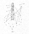
- FIG. 1 illustrates a concentrated solar power plant set-up, in accordance with an exemplary embodiment of the present disclosure
- FIG. 2 illustrates a solar receiver tube and support arrangements, in accordance with an exemplary embodiment of the present disclosure
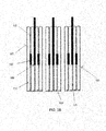
- FIGS. 3A and 3B respectively, illustrate cross-sectional top and side views of the solar receiver tube and support arrangements, along axis Y-Y' and axis Z-Z', in accordance with an exemplary embodiment of the present disclosure.
- the solar power plant set-up 1000 includes a concentrated solar tower assembly 100 having a tower structure 200 and a solar receiver 300 placed at the top thereof, where solar rays are concentrated from a heliostat 400 for the production of electricity.
- the solar receiver 300 includes various tubes or tube panels through which fluid flows for carrying the solar heat accumulated therein due to concentrated solar rays by the heliostat 400.
- FIG. 2 illustrates a solar receiver tube and support arrangements that may be successfully utilized in relation to any solar receiver, such as the solar receiver 300, as known there, in accordance with an exemplary embodiment of the present disclosure.
- the tower structure 200 and the solar receiver 300 may include a variety of components for performing their assigned purpose, and only those components are shown that are relevant for the description of various embodiments of the present disclosure.
- FIGS. 3A and 3B which, respectively, illustrate cross-sectional top and side views of the solar receiver tube and support arrangements, along axis Y-Y' and axis Z-Z', in accordance with an exemplary embodiment of the present disclosure.
- An arrangement of the solar receiver 300 (hereinafter referred to 'solar receiver arrangement 300') includes a plurality of receiver panels 500 arranged adjacent to one another. Each panel 500 has a plurality of tubes 510 substantially parallel and coupled tangentially to one another, and extends for fluidly connecting an inlet header of the panel 500 to an outlet header of the panel 500.
- the tubes 510 are primarily grouped in particular numbers that are predetermined as per the need and accordingly arranged. For example, as shown in FIGS. 3A and 3B , four tubes 510 are grouped to configure one panel 500. However, without departing from the scope of the present disclosure, any numbers of tubes, such as the tubes 510, may be grouped to configure the panel 500.
- the grouped tubes 510 are arranged adjacent to one another in such a manner that an outer surface of one tube 510 tangentially touched an outer surface of the adjacent tube 510, thereby forming a crotch portion 520 between a pair of tubes, such as the tubes 510.
- Such grouped and arranged tubes 510 are coupled together to form the panels 500, and accordingly the panels 500 are arranged to form the solar receiver arrangement 300 by utilizing a support structure 600.
- the support structure 600 includes a plurality of tie members, such as tie members 700.
- the tie members 700 are utilized for coupling the plurality of tubes 510 arranged tangentially to one another, for configuring at least one receiver panel, such as the panels 500.
- At least one tie member 700 may be placed in the at least one crotch portion 520 of the pair of tubes 510 for being coupled therebetween, thereby coupling the pair of tubes 510 together.
- two crotch portions 520 one opposite to other, are formed while tangentially arranging the pair of tubes 510. Therefore in an example, as shown in FIGS.
- two tie members 700 may be utilized for coupling the two adjacent tubes 510, in which one tie member 700 is placed in each crotch portion 520, configured by tangentially orientating the pair of tubes 510.
- only tie member 700 may be utilized for coupling the pair of tubes 510 by coupling in only one crotch portion 520 of the pair of tubes 510.
- the tie members 700 are coupled to the tubes 510 via welding, without departing the scope of other coupling methods or structures.
- the tie members 700 are substantially short-length rods that are welded in the crotch portion 520 between the pair of the tubes 510 for coupling thereto by substantially covering a relatively small region thereof for maximum direct solar rays' incident directly over the tubes 510, ensuring maximum exposure of the tubes 510 to heat flux.
- the support structure 600 or its associated components, such as the tie members 700 may be precluded from the area of the panel 500 where there is solar flux.
- the support structure 600 further includes a plurality of panel support members, such as a panel support member 800, utilized for the assembly and grouping of the panels 500 for the formation of the solar receiver arrangement 300.
- a panel support member 800 is coupled to the panel 500 selectively in the at least one crotch portion 520 between any of the pair of tubes 510.
- the panel support members 800 may be coupled to the panel 500 selectively in the at least one crotch portion 520 lying substantially at a middle region of the panels 500.
- the support members 800 may be coupled to at any suitable region of the panel 500.
- the panel support member 800 are coupled to the panel 500, there the tie members 700 are not coupled in the crotch portion 520 of any of the pair of tubes 510.
- the panel support members 800 are coupled in the crotch portion 520 between the pair of tubes 510 via welding, without departing the scope of other couplings.
- the panels 500 are arranged adjacent to one another, in at least one of a spaced apart configuration and a closely associated configuration, for forming the solar receiver arrangement 300.
- a predetermined distance is maintained between two panels 500.
- the predetermined distance may be maintained at zero. Any of the configurations may be chosen as per the requirement and need.
- arranged panels 500 are held up in an engaged position, which is obtained by at least one latching member 900.
- the latching member 900 is configured to detachably attach the plurality of panel support members 800 for engaging the plurality of receiver panels 500.
- the latching member 900 may extend from any supporting element of the solar receiver arrangement 300.
- the latching member 900 may be a hanger rod extending from the solar receiver arrangement 300 structure's portion 310.
- a latching member 900 includes a channel member 910 configured at a distal end thereof.
- the channel member 910 of the latching member 900 receives the panel support member 800, which in one embodiment is the rod, (as shown in FIG. 2 ) to detachably attach thereto for engaging the plurality of receiver panels 500 to configure the solar receiver arrangement 300.
- the solar receiver arrangement and support structure are advantageous in various scopes.
- the support member, particularly the tie members are applicable for use in tying together the tubes for configuring the panel, wherein the tubes to be joined bear a tangential relationship to each other.
- the support arrangement, particularly the panel support member is capable of performing the function of providing support to the tube panels in conjunction with the latching member for forming the solar receiver arrangement.
- the solar receiver arrangement and a support structure are substantially more manageable in terms of assembly and maintenance, and ensure maximum exposure to heat flux, and reduce local stress development during connection thereof due to the involvement of a fewer number of components.
- the solar receiver arrangement and support structure may also be capable of being fabricated and assembled with relative ease.
- the solar receiver arrangement and support structure may also be economical to produce and to employ.
- apart for the aforementioned advantages such a construction method or sequence and the plant include various other advantages of today's plants and method.
Landscapes
- Engineering & Computer Science (AREA)
- Mechanical Engineering (AREA)
- Physics & Mathematics (AREA)
- Life Sciences & Earth Sciences (AREA)
- Sustainable Development (AREA)
- Sustainable Energy (AREA)
- Thermal Sciences (AREA)
- Chemical & Material Sciences (AREA)
- Combustion & Propulsion (AREA)
- General Engineering & Computer Science (AREA)
- Photovoltaic Devices (AREA)
Abstract

Description
- The present disclosure relates to solar power plants, and, more particularly, to a solar receiver arrangement and a support structure.
- A concentrated solar power plant use a solar receiver steam generator located at an elevation of a support tower, where the solar rays are focused for utilizing the solar heat to produce electricity.
- Solar receiver steam generators generally include various fluid carrying tubes that are heated by focusing sunrays thereon, in turn heating fluid to be utilized for producing electricity. Grouping and arrangement of tubes and support elements for supporting such grouped and arranged tubes are quite important and critical from the point of view of effectively utilizing heat flux of the sunrays without failure.
- For examples, if the support element designs restrict a substantial amount of heat flux, the fluid heating may be affected. Further, if the supporting elements utilize a greater number of components in order to support or attach individual tube or grouped tubes, the chances of developing high local stress at or around attachment regions are high. Furthermore, a greater number of components in the support element, depending upon the grouping and arrangement of the tubes, would be unmanageable from the view of assembly and maintenance.
- While previously known support and tube arrangements may have generally been considered satisfactory for their intended purposes, there has remained a need in the art for solar receivers that can improve tube and support arrangements to make it substantially more manageable in terms of assembly and maintenance, more exposure to heat flux, and reduction of local stress development.
- The present disclosure provides a solar receiver arrangement and a support structure that will be presented in the following simplified summary to provide a basic understanding of one or more aspects of the disclosure that are intended to overcome the discussed drawbacks, but to include all advantages thereof along with providing some additional advantages. This summary is not an extensive overview of the disclosure. It is intended to neither identify key or critical elements of the disclosure, nor to delineate the scope of the present disclosure. Rather, the sole purpose of this summary is to present some concepts of the disclosure, its objects and advantages in a simplified form as a prelude to the more detailed description that is presented hereinafter.
- An object of the present disclosure is to describe a solar receiver arrangement and a support structure that may be substantially more manageable in terms of assemblage and maintenance, may ensure maximum exposure to heat flux, and reduces local stress development while connection thereof. A further object of the present disclosure to describe such a support structure, that is capable of particularly applicable for use in tying and supporting together the tubes of the solar receiver panels, wherein the tubes to be joined bear a tangential relationship to each other. Yet another object is to describe a solar receiver arrangement and a support structure that is capable of being fabricated and assembled with a relative ease. Still a further object of the present disclosure is to describe such solar receiver arrangement and support structure that is economical to produce and to employ. Various other objects and features of the present disclosure will be apparent from the following detailed description.
- The above noted and other objects may be achieved by a support structure for a solar receiver arrangement and the solar receiver arrangement itself.
- In one aspect of the present disclosure, the support structure for a solar receiver arrangement comprises: a plurality of tie members tangentially coupling a plurality of tubes, for configuring at least one receiver panel, in such a manner that at least one tie member is coupled in at least one crotch portion between a pair of tubes; a plurality of panel support members, at least one panel support member of the plurality of panel support members coupled to the receiver panel selectively in the at least one crotch portion between a pair of tubes; and at least one latching member configured to detachably attach the plurality of panel support members for engaging the plurality of receiver panels.
- In one embodiment, each of the plurality of tie members are substantially short-length rods that are welded in the crotch portion between the pair of the tubes for coupling the pair of tubes by covering a substantially small region thereof to have maximum direct solar rays incident directly over the tubes. In a further embodiment, at least one tie member may be coupled in both the opposite crotch portions of the pair of tubes.
- In another embodiment, each of the plurality of panel support members is coupled to at least one receiver panel selectively in the at least one crotch portion, lying substantially at a middle region of the plurality of receiver panels.
- In yet another embodiment, the at least one latching member comprises a channel member to receive the plurality of panel support members to detachably attach thereto. In such an embodiment, each of the plurality of panel support members may be a longitudinally extending threaded rod that may be received in the channel for engaging the plurality of receiver panels.
- In another aspect, the solar receiver arrangement comprises: a plurality of receiver panels arranged adjacent to one another, each panel having a plurality of tubes coupled tangentially to one another; a plurality of tie members coupling the plurality of tangentially arranged tubes in such a manner that at least one tie member is coupled in at least one crotch portion between a pair of tubes; and a plurality of panel support members, at least one panel support member of the plurality of panel support members coupled to at least one receiver panel selectively in the at least one crotch portion between a pair of tubes.
- In one embodiment, the plurality of receiver panels may be arranged adjacent to one another, in at least one of a spaced apart configuration and a closely associated configuration.
- In another embodiment, the solar receiver arrangement further comprises at least one latching member configured to detachably attach the plurality of panel support members for engaging the plurality of receiver panels. In a further embodiment, the at least one latching member comprises a channel member to receive the plurality of panel support members to detachably attach thereto. In such an embodiment, each of the plurality of panel support members include a longitudinally extending threaded rod that is received in the channel for engaging the plurality of receiver panels.
- In another aspect, a solar receiver panel and a method for making are provided. The solar receiver panel comprises: a plurality of tubes tangential to one another; a plurality of tie members for coupling the plurality of tangentially arranged tubes in such a manner that at least one tie member is coupled in at least one crotch portion between a pair of tubes; and at least one panel support member coupled to the plurality of tubes selectively in the at least one crotch portion between a pair of tubes.
- Further, the method for making a solar receiver panel comprises: arranging a plurality of tubes tangentially to one another; welding a plurality of tie members for coupling the plurality of tangential arranged tubes in such a manner that at least one tie member is welded in at least one crotch portion between a pair of tubes; and welding at least one panel support member to the plurality of tubes selectively in the at least one crotch portion between a pair of tubes.
- These together with the other aspects of the present disclosure, along with the various features of novelty that characterize the present disclosure, are pointed out with particularity in the present disclosure. For a better understanding of the present disclosure, its operating advantages, and its uses, reference should be made to the accompanying drawings and descriptive matter in which there are illustrated exemplary embodiments of the present disclosure.
- The advantages and features of the present disclosure will better understood with reference to the following detailed description and claims taken in conjunction with the accompanying drawing, wherein like elements are identified with like symbols, and in which:
-
FIG. 1 illustrates a concentrated solar power plant set-up, in accordance with an exemplary embodiment of the present disclosure; -
FIG. 2 illustrates a solar receiver tube and support arrangements, in accordance with an exemplary embodiment of the present disclosure; and -
FIGS. 3A and3B , respectively, illustrate cross-sectional top and side views of the solar receiver tube and support arrangements, along axis Y-Y' and axis Z-Z', in accordance with an exemplary embodiment of the present disclosure. - Like reference numerals refer to like parts throughout the description of several views of the drawings.
- For a thorough understanding of the present disclosure, reference is to be made to the following detailed description, including the appended claims, in connection with the above-described drawings. In the following description, for purposes of explanation, numerous specific details are set forth in order to provide a thorough understanding of the present disclosure. It will be apparent, however, to one skilled in the art that the present disclosure can be practiced without these specific details. In other instances, structures and devices are shown in block diagrams form only, in order to avoid obscuring the disclosure. Reference in this specification to "one embodiment," "an embodiment," "another embodiment," "various embodiments," means that a particular feature, structure, or characteristic described in connection with the embodiment is included in at least one embodiment of the present disclosure. The appearance of the phrase "in one embodiment" in various places in the specification are not necessarily all referring to the same embodiment, nor are separate or alternative embodiments mutually exclusive of other embodiments. Moreover, various features are described which may be exhibited by some embodiments and not by others. Similarly, various requirements are described which may be requirements for some embodiments but may not be of other embodiment's requirement.
- Although the following description contains many specifics for the purposes of illustration, anyone skilled in the art will appreciate that many variations and/or alterations to these details are within the scope of the present disclosure. Similarly, although many of the features of the present disclosure are described in terms of each other, or in conjunction with each other, one skilled in the art will appreciate that many of these features can be provided independently of other features. Accordingly, this description of the present disclosure is set forth without any loss of generality to, and without imposing limitations upon, the present disclosure. Further, the relative terms, such as "inner," "outer," "upper," "lower" and the like, herein do not denote any order, elevation or importance, but rather are used to distinguish one element over another. Further, the terms "a," "an," and "plurality" herein do not denote a limitation of quantity, but rather denote the presence of at least one of the referenced item.
- Referring now to
FIG. 1 , an example of a solar power plant set-up 1000 is illustrated in accordance with an exemplary embodiment of the present disclosure. The solar power plant set-up 1000 includes a concentratedsolar tower assembly 100 having atower structure 200 and asolar receiver 300 placed at the top thereof, where solar rays are concentrated from aheliostat 400 for the production of electricity. Specifically, thesolar receiver 300 includes various tubes or tube panels through which fluid flows for carrying the solar heat accumulated therein due to concentrated solar rays by theheliostat 400. In as much as the construction and arrangement of the solar power plant set-up 1000 having thetower 100, thesolar receiver 300, and theheliostat 400 are all well-known to those skilled in the art, it is not deemed necessary for purposes of acquiring an understanding of the present disclosure, that there be recited herein all of the constructional details and explanation thereof. Rather, it is deemed sufficient to simply note thatFIG. 2 illustrates a solar receiver tube and support arrangements that may be successfully utilized in relation to any solar receiver, such as thesolar receiver 300, as known there, in accordance with an exemplary embodiment of the present disclosure. Further, it should be understood that thetower structure 200 and thesolar receiver 300 may include a variety of components for performing their assigned purpose, and only those components are shown that are relevant for the description of various embodiments of the present disclosure. - The solar receiver tube and support arrangements as illustrated in
FIG. 2 , will also be described in conjunction withFIGS. 3A and3B , which, respectively, illustrate cross-sectional top and side views of the solar receiver tube and support arrangements, along axis Y-Y' and axis Z-Z', in accordance with an exemplary embodiment of the present disclosure. An arrangement of thesolar receiver 300, (hereinafter referred to 'solar receiver arrangement 300') includes a plurality ofreceiver panels 500 arranged adjacent to one another. Eachpanel 500 has a plurality oftubes 510 substantially parallel and coupled tangentially to one another, and extends for fluidly connecting an inlet header of thepanel 500 to an outlet header of thepanel 500. Thetubes 510 are primarily grouped in particular numbers that are predetermined as per the need and accordingly arranged. For example, as shown inFIGS. 3A and3B , fourtubes 510 are grouped to configure onepanel 500. However, without departing from the scope of the present disclosure, any numbers of tubes, such as thetubes 510, may be grouped to configure thepanel 500. The groupedtubes 510 are arranged adjacent to one another in such a manner that an outer surface of onetube 510 tangentially touched an outer surface of theadjacent tube 510, thereby forming acrotch portion 520 between a pair of tubes, such as thetubes 510. Such grouped and arrangedtubes 510 are coupled together to form thepanels 500, and accordingly thepanels 500 are arranged to form thesolar receiver arrangement 300 by utilizing asupport structure 600. - The
support structure 600 includes a plurality of tie members, such astie members 700. Thetie members 700 are utilized for coupling the plurality oftubes 510 arranged tangentially to one another, for configuring at least one receiver panel, such as thepanels 500. At least onetie member 700 may be placed in the at least onecrotch portion 520 of the pair oftubes 510 for being coupled therebetween, thereby coupling the pair oftubes 510 together. Generally, twocrotch portions 520, one opposite to other, are formed while tangentially arranging the pair oftubes 510. Therefore in an example, as shown inFIGS. 3A and3B , twotie members 700 may be utilized for coupling the twoadjacent tubes 510, in which onetie member 700 is placed in eachcrotch portion 520, configured by tangentially orientating the pair oftubes 510. Alternatively, only tiemember 700 may be utilized for coupling the pair oftubes 510 by coupling in only onecrotch portion 520 of the pair oftubes 510. In a preferred embodiment of the present disclosure, thetie members 700 are coupled to thetubes 510 via welding, without departing the scope of other coupling methods or structures. Further, in one embodiment, thetie members 700 are substantially short-length rods that are welded in thecrotch portion 520 between the pair of thetubes 510 for coupling thereto by substantially covering a relatively small region thereof for maximum direct solar rays' incident directly over thetubes 510, ensuring maximum exposure of thetubes 510 to heat flux. Thesupport structure 600 or its associated components, such as thetie members 700 may be precluded from the area of thepanel 500 where there is solar flux. - Coupling the desired number of grouped and arranged
tubes 510 ensures the formation of a required number of thepanels 500 that may be utilized for configuring thesolar receiver arrangement 300. For configuration of thesolar receiver arrangement 300, thesupport structure 600 further includes a plurality of panel support members, such as apanel support member 800, utilized for the assembly and grouping of thepanels 500 for the formation of thesolar receiver arrangement 300. Specifically, at least onepanel support member 800 is coupled to thepanel 500 selectively in the at least onecrotch portion 520 between any of the pair oftubes 510. For example, thepanel support members 800 may be coupled to thepanel 500 selectively in the at least onecrotch portion 520 lying substantially at a middle region of thepanels 500. Alternatively, thesupport members 800 may be coupled to at any suitable region of thepanel 500. Notably, where thepanel support member 800 are coupled to thepanel 500, there thetie members 700 are not coupled in thecrotch portion 520 of any of the pair oftubes 510. In a preferred embodiment of the present disclosure, thepanel support members 800 are coupled in thecrotch portion 520 between the pair oftubes 510 via welding, without departing the scope of other couplings. - Further, the
panels 500, each with thepanel support members 800, are arranged adjacent to one another, in at least one of a spaced apart configuration and a closely associated configuration, for forming thesolar receiver arrangement 300. In the spaced apart configuration, a predetermined distance is maintained between twopanels 500. Further, in the closely associated configuration, the predetermined distance may be maintained at zero. Any of the configurations may be chosen as per the requirement and need. As so desired, arrangedpanels 500 are held up in an engaged position, which is obtained by at least one latchingmember 900. The latchingmember 900 is configured to detachably attach the plurality ofpanel support members 800 for engaging the plurality ofreceiver panels 500. The latchingmember 900 may extend from any supporting element of thesolar receiver arrangement 300. In one embodiment, the latchingmember 900 may be a hanger rod extending from thesolar receiver arrangement 300 structure'sportion 310. Such a latchingmember 900 includes achannel member 910 configured at a distal end thereof. Thechannel member 910 of the latchingmember 900 receives thepanel support member 800, which in one embodiment is the rod, (as shown inFIG. 2 ) to detachably attach thereto for engaging the plurality ofreceiver panels 500 to configure thesolar receiver arrangement 300. - The solar receiver arrangement and support structure are advantageous in various scopes. The support member, particularly the tie members, are applicable for use in tying together the tubes for configuring the panel, wherein the tubes to be joined bear a tangential relationship to each other. Further, the support arrangement, particularly the panel support member, is capable of performing the function of providing support to the tube panels in conjunction with the latching member for forming the solar receiver arrangement. Furthermore, the solar receiver arrangement and a support structure are substantially more manageable in terms of assembly and maintenance, and ensure maximum exposure to heat flux, and reduce local stress development during connection thereof due to the involvement of a fewer number of components. The solar receiver arrangement and support structure may also be capable of being fabricated and assembled with relative ease. Furthermore, the solar receiver arrangement and support structure may also be economical to produce and to employ. Moreover, apart for the aforementioned advantages, such a construction method or sequence and the plant include various other advantages of today's plants and method.
- The foregoing descriptions of specific embodiments of the present disclosure have been presented for purposes of illustration and description. They are not intended to be exhaustive or to limit the present disclosure to the precise forms disclosed, and clearly many modifications and variations are possible in light of the above description. The embodiments were chosen and described in order to best explain the principles of the present disclosure and its practical application, to thereby enable others skilled in the art to best utilize the present disclosure and various embodiments with various modifications as are suited to the particular use contemplated. It is understood that various omission and substitutions of equivalents are contemplated as circumstance may suggest or render expedient, but such are intended to cover the application or implementation without departing from the spirit or scope of the claims of the present disclosure.
-
- 1000
- Solar power plant
- 100
- solar tower assembly
- 200
- Tower structure
- 300
- Solar receiver arrangement
- 310
- Solar receiver structure portion
- 400
- Heliostat
- 500
- Receiver panel, panel
- 510
- Tubes
- 520
- Crotch portion
- 600
- Support structure
- 700
- Tie members
- 800
- Panel support member
- 900
- Latching member
- 910
- Channel member
Claims (13)
- A support structure for a solar receiver arrangement, the support structure comprising:a plurality of tubes arranged to form at least one crotch portion between a pair of tubes;a plurality of tie members tangentially coupling the plurality of tubes to form at least one receiver panel, such that at least one tie member is coupled in the at least one crotch portion;a plurality of panel support members, at least one of said plurality of panel support members coupled to the receiver panel in the at least one crotch portion; andat least one latching member configured to detachably attach the plurality of panel support members and to engage the at least one receiver panel.
- The support structure as claimed in claim 1, wherein each of the plurality of tie members comprises a substantially short-length rod that is welded in and coupled to the at least one crotch portion between said pair of the tubes, each of the plurality of tie members covering a substantially small region thereof to permit maximum direct solar rays incident directly over said tubes.
- The support structure as claimed in claim 1, wherein:the plurality of tubes forms at least two opposite crotch portions between a pair of tubes; andat least one tie member is coupled in both of said at least two opposite crotch portions.
- The support structure as claimed in claim 1, wherein each of the plurality of panel support members is coupled to at least one receiver panel in at least one crotch portion lying substantially at a middle region of the plurality of receiver panels.
- The support structure as claimed in claim 1, wherein the at least one latching member comprises a channel member configured to receive the plurality of panel support members and to detachably attach thereto.
- The support structure as claimed in claim 5, wherein each of the plurality of panel support members comprises a longitudinally extending threaded rod configured to be received in the channel and engage the plurality of receiver panels.
- A solar receiver arrangement comprising:a plurality of receiver panels arranged adjacent to one another, each panel having a plurality of tubes coupled tangentially to one another, said plurality of tubes forming at least one crotch portion therebetween;a plurality of tie members coupling the plurality of tangentially arranged tubes such that at least one tie member is coupled in said at least one crotch portion; anda plurality of panel support members, at least one panel support member of said plurality of panel support members being coupled to at least one of said plurality of receiver panels in said at least one crotch portion.
- The solar receiver arrangement as claimed in claim 7, wherein the receiver panels of said plurality of receiver panels are arranged adjacent to one another, in at least one of a spaced apart configuration and a closely associated configuration.
- The solar receiver arrangement as claimed in claim 7, further comprising:at least one latching member configured to detachably attach the plurality of panel support members to engage the plurality of receiver panels.
- The solar receiver arrangement as claimed in claim 9, wherein the at least one latching member comprises a channel member configured to receive the plurality of panel support members to detachably attach to said channel member.
- The solar receiver arrangement as claimed in claim 9, wherein each of the plurality of panel support members comprises a longitudinally extending threaded rod configured to be received in the channel to engage the plurality of receiver panels.
- A solar receiver panel comprising:a plurality of tubes tangential to one another and forming at least one crotch portion;a plurality of tie members configured to couple the tangentially arranged plurality of tubes such that at least one tie member is coupled in said at least one crotch portion; andat least one panel support member coupled to the plurality of tubes in at least one crotch portion.
- A method for making a solar receiver panel, the method comprising:arranging a plurality of tubes tangentially to one another and forming at least one crotch portion;welding a plurality of tie members to couple the tangentially arranged plurality of tubes such that at least one tie member is welded in at least one crotch portion between a pair of tubes; andwelding at least one panel support member to the plurality of tubes in at least one crotch portion.
Applications Claiming Priority (1)
| Application Number | Priority Date | Filing Date | Title |
|---|---|---|---|
| US13/675,153 US9341392B2 (en) | 2012-11-13 | 2012-11-13 | Solar receiver panel and support structure |
Publications (2)
| Publication Number | Publication Date |
|---|---|
| EP2730857A1 true EP2730857A1 (en) | 2014-05-14 |
| EP2730857B1 EP2730857B1 (en) | 2019-01-09 |
Family
ID=49554090
Family Applications (1)
| Application Number | Title | Priority Date | Filing Date |
|---|---|---|---|
| EP13192080.3A Not-in-force EP2730857B1 (en) | 2012-11-13 | 2013-11-08 | Solar receiver panel and support structure |
Country Status (5)
| Country | Link |
|---|---|
| US (1) | US9341392B2 (en) |
| EP (1) | EP2730857B1 (en) |
| CN (1) | CN103808044B (en) |
| ES (1) | ES2710459T3 (en) |
| ZA (1) | ZA201308498B (en) |
Families Citing this family (1)
| Publication number | Priority date | Publication date | Assignee | Title |
|---|---|---|---|---|
| ES2554828T3 (en) * | 2012-09-19 | 2015-12-23 | Alstom Technology Ltd. | Set and method of concentrated solar tower |
Citations (5)
| Publication number | Priority date | Publication date | Assignee | Title |
|---|---|---|---|---|
| EP0106687A2 (en) * | 1982-10-14 | 1984-04-25 | The Babcock & Wilcox Company | Tube panels and solar receivers incorporating such panels |
| EP0106688A2 (en) * | 1982-10-14 | 1984-04-25 | The Babcock & Wilcox Company | Solar receivers |
| US20100101564A1 (en) * | 2008-10-24 | 2010-04-29 | Iannacchione Steven P | Shop-assembled solar receiver heat exchanger |
| US20100199977A1 (en) * | 2009-02-12 | 2010-08-12 | Babcock Power Services, Inc. | Panel support system for solar boilers |
| US20100199980A1 (en) * | 2009-02-12 | 2010-08-12 | Babcock Power Services, Inc. | Expansion joints for panels in solar boilers |
Family Cites Families (7)
| Publication number | Priority date | Publication date | Assignee | Title |
|---|---|---|---|---|
| US3285504A (en) | 1964-12-10 | 1966-11-15 | Gen Motors Corp | Refrigerant apparatus |
| US3375628A (en) | 1965-07-01 | 1968-04-02 | Foster Whceler Corp | Insulated wall construction for heated surfaces |
| US4412510A (en) | 1978-11-03 | 1983-11-01 | Combustion Engineering, Inc. | Flexible tie for tangent tube construction |
| US4285335A (en) * | 1979-07-30 | 1981-08-25 | Reliable Metal Products, Inc. | Solar energy collector panel |
| US4384550A (en) * | 1980-12-19 | 1983-05-24 | Rockwell International Corporation | Thermal receiver |
| US5482233A (en) | 1994-02-28 | 1996-01-09 | Rockwell International Corporation | Dismountable, slidable tube support clip for accommodating high-temperature thermal expansion |
| US5862800A (en) | 1996-09-27 | 1999-01-26 | Boeing North American, Inc. | Molten nitrate salt solar central receiver of low cycle fatigue 625 alloy |
-
2012
- 2012-11-13 US US13/675,153 patent/US9341392B2/en not_active Expired - Fee Related
-
2013
- 2013-11-08 ES ES13192080T patent/ES2710459T3/en active Active
- 2013-11-08 EP EP13192080.3A patent/EP2730857B1/en not_active Not-in-force
- 2013-11-12 ZA ZA2013/08498A patent/ZA201308498B/en unknown
- 2013-11-13 CN CN201310756821.3A patent/CN103808044B/en not_active Expired - Fee Related
Patent Citations (5)
| Publication number | Priority date | Publication date | Assignee | Title |
|---|---|---|---|---|
| EP0106687A2 (en) * | 1982-10-14 | 1984-04-25 | The Babcock & Wilcox Company | Tube panels and solar receivers incorporating such panels |
| EP0106688A2 (en) * | 1982-10-14 | 1984-04-25 | The Babcock & Wilcox Company | Solar receivers |
| US20100101564A1 (en) * | 2008-10-24 | 2010-04-29 | Iannacchione Steven P | Shop-assembled solar receiver heat exchanger |
| US20100199977A1 (en) * | 2009-02-12 | 2010-08-12 | Babcock Power Services, Inc. | Panel support system for solar boilers |
| US20100199980A1 (en) * | 2009-02-12 | 2010-08-12 | Babcock Power Services, Inc. | Expansion joints for panels in solar boilers |
Also Published As
| Publication number | Publication date |
|---|---|
| US20140130793A1 (en) | 2014-05-15 |
| CN103808044B (en) | 2017-09-19 |
| ZA201308498B (en) | 2014-07-30 |
| US9341392B2 (en) | 2016-05-17 |
| CN103808044A (en) | 2014-05-21 |
| EP2730857B1 (en) | 2019-01-09 |
| ES2710459T3 (en) | 2019-04-25 |
Similar Documents
| Publication | Publication Date | Title |
|---|---|---|
| WO2009121030A3 (en) | Solar thermal receiver for medium-and high-temperature applications | |
| KR20120117748A (en) | Heat exchanger for generating steam for solar power plants | |
| CL2011002000A1 (en) | Heat exchange device configured to capture energy by radiation comprising at least one elementary exchanger in the form of a flag containing an inlet and an outlet manifold, several exchange tubes connected respectively to the inlet and outlet manifold. | |
| US9341392B2 (en) | Solar receiver panel and support structure | |
| EP2730856B1 (en) | Boiler for solar receiver | |
| EP2955461B1 (en) | Improved solar receiver configuration | |
| EP2993425A1 (en) | Thermally-insulated tubular-tower solar receiver comprising a system for harnessing energy losses | |
| RU105730U1 (en) | SPIRAL HEAT EXCHANGER COIL | |
| US9134043B2 (en) | Heat transfer passes for solar boilers | |
| KR20140073494A (en) | Solar radiation receiver | |
| CL2012003370A1 (en) | Concave receiver for stirling disc, has tubes whose surface affects a concentrated beam of sunlight, collectors, deposits, expansion dome, where the tubes leave perpendicularly from one collector and reach perpendicularly to another, also have a straight part that runs from the inside each collector to the place where the curvature of the tube begins and a central part in the shape of an arc of circumference; and method. | |
| US9765992B2 (en) | Solar receiver | |
| CN103930719B (en) | Solar thermal power generation equipment | |
| US20170363329A1 (en) | Solar receiver having improved heliostat field performance | |
| RU102773U1 (en) | PASSIVE HEAT REMOVAL SYSTEM HEAT EXCHANGER MODULE | |
| Gardner et al. | Development of a solar thermal supercritical steam generator | |
| CN106556156A (en) | Light heat-receiving apparatus and tower type solar in a kind of tower power station utilize device | |
| JP2012063119A (en) | Moisture separating heating apparatus | |
| CN201392034Y (en) | Lens light-concentrating and heat-collecting vacuum tube | |
| CN203550249U (en) | Tower-type solar thermal power plant receiver light blocking structure | |
| RU2752410C2 (en) | Section of modules of vertical steam generator | |
| RU2489642C1 (en) | Heat exchanger | |
| RU2012116497A (en) | HEAT EXCHANGE DEVICE | |
| US20140014091A1 (en) | Method of using a stationary dome-shaped structure composed of linked converging lenses as a solar collector system | |
| RU2017117935A (en) | CONNECTING SOLAR MANIFOLD WITH U-SHAPED HEAT PIPES |
Legal Events
| Date | Code | Title | Description |
|---|---|---|---|
| PUAI | Public reference made under article 153(3) epc to a published international application that has entered the european phase |
Free format text: ORIGINAL CODE: 0009012 |
|
| 17P | Request for examination filed |
Effective date: 20131108 |
|
| AK | Designated contracting states |
Kind code of ref document: A1 Designated state(s): AL AT BE BG CH CY CZ DE DK EE ES FI FR GB GR HR HU IE IS IT LI LT LU LV MC MK MT NL NO PL PT RO RS SE SI SK SM TR |
|
| AX | Request for extension of the european patent |
Extension state: BA ME |
|
| R17P | Request for examination filed (corrected) |
Effective date: 20131108 |
|
| RAP1 | Party data changed (applicant data changed or rights of an application transferred) |
Owner name: GENERAL ELECTRIC TECHNOLOGY GMBH |
|
| REG | Reference to a national code |
Ref country code: DE Ref legal event code: R079 Ref document number: 602013049476 Country of ref document: DE Free format text: PREVIOUS MAIN CLASS: F24J0002070000 Ipc: F24S0020200000 |
|
| RIC1 | Information provided on ipc code assigned before grant |
Ipc: F24S 10/70 20180101ALI20180622BHEP Ipc: F24S 80/30 20180101ALI20180622BHEP Ipc: F24S 20/20 20180101AFI20180622BHEP |
|
| GRAP | Despatch of communication of intention to grant a patent |
Free format text: ORIGINAL CODE: EPIDOSNIGR1 |
|
| STAA | Information on the status of an ep patent application or granted ep patent |
Free format text: STATUS: GRANT OF PATENT IS INTENDED |
|
| INTG | Intention to grant announced |
Effective date: 20180808 |
|
| RIN1 | Information on inventor provided before grant (corrected) |
Inventor name: PAYNE, RONALD G |
|
| GRAS | Grant fee paid |
Free format text: ORIGINAL CODE: EPIDOSNIGR3 |
|
| GRAA | (expected) grant |
Free format text: ORIGINAL CODE: 0009210 |
|
| STAA | Information on the status of an ep patent application or granted ep patent |
Free format text: STATUS: THE PATENT HAS BEEN GRANTED |
|
| AK | Designated contracting states |
Kind code of ref document: B1 Designated state(s): AL AT BE BG CH CY CZ DE DK EE ES FI FR GB GR HR HU IE IS IT LI LT LU LV MC MK MT NL NO PL PT RO RS SE SI SK SM TR |
|
| REG | Reference to a national code |
Ref country code: GB Ref legal event code: FG4D |
|
| REG | Reference to a national code |
Ref country code: CH Ref legal event code: EP Ref country code: AT Ref legal event code: REF Ref document number: 1087807 Country of ref document: AT Kind code of ref document: T Effective date: 20190115 |
|
| REG | Reference to a national code |
Ref country code: IE Ref legal event code: FG4D |
|
| REG | Reference to a national code |
Ref country code: DE Ref legal event code: R096 Ref document number: 602013049476 Country of ref document: DE |
|
| REG | Reference to a national code |
Ref country code: ES Ref legal event code: FG2A Ref document number: 2710459 Country of ref document: ES Kind code of ref document: T3 Effective date: 20190425 |
|
| REG | Reference to a national code |
Ref country code: NL Ref legal event code: MP Effective date: 20190109 |
|
| REG | Reference to a national code |
Ref country code: LT Ref legal event code: MG4D |
|
| PG25 | Lapsed in a contracting state [announced via postgrant information from national office to epo] |
Ref country code: NL Free format text: LAPSE BECAUSE OF FAILURE TO SUBMIT A TRANSLATION OF THE DESCRIPTION OR TO PAY THE FEE WITHIN THE PRESCRIBED TIME-LIMIT Effective date: 20190109 |
|
| REG | Reference to a national code |
Ref country code: AT Ref legal event code: MK05 Ref document number: 1087807 Country of ref document: AT Kind code of ref document: T Effective date: 20190109 |
|
| PG25 | Lapsed in a contracting state [announced via postgrant information from national office to epo] |
Ref country code: LT Free format text: LAPSE BECAUSE OF FAILURE TO SUBMIT A TRANSLATION OF THE DESCRIPTION OR TO PAY THE FEE WITHIN THE PRESCRIBED TIME-LIMIT Effective date: 20190109 Ref country code: FI Free format text: LAPSE BECAUSE OF FAILURE TO SUBMIT A TRANSLATION OF THE DESCRIPTION OR TO PAY THE FEE WITHIN THE PRESCRIBED TIME-LIMIT Effective date: 20190109 Ref country code: PL Free format text: LAPSE BECAUSE OF FAILURE TO SUBMIT A TRANSLATION OF THE DESCRIPTION OR TO PAY THE FEE WITHIN THE PRESCRIBED TIME-LIMIT Effective date: 20190109 Ref country code: NO Free format text: LAPSE BECAUSE OF FAILURE TO SUBMIT A TRANSLATION OF THE DESCRIPTION OR TO PAY THE FEE WITHIN THE PRESCRIBED TIME-LIMIT Effective date: 20190409 Ref country code: SE Free format text: LAPSE BECAUSE OF FAILURE TO SUBMIT A TRANSLATION OF THE DESCRIPTION OR TO PAY THE FEE WITHIN THE PRESCRIBED TIME-LIMIT Effective date: 20190109 Ref country code: PT Free format text: LAPSE BECAUSE OF FAILURE TO SUBMIT A TRANSLATION OF THE DESCRIPTION OR TO PAY THE FEE WITHIN THE PRESCRIBED TIME-LIMIT Effective date: 20190509 |
|
| PG25 | Lapsed in a contracting state [announced via postgrant information from national office to epo] |
Ref country code: IS Free format text: LAPSE BECAUSE OF FAILURE TO SUBMIT A TRANSLATION OF THE DESCRIPTION OR TO PAY THE FEE WITHIN THE PRESCRIBED TIME-LIMIT Effective date: 20190509 Ref country code: BG Free format text: LAPSE BECAUSE OF FAILURE TO SUBMIT A TRANSLATION OF THE DESCRIPTION OR TO PAY THE FEE WITHIN THE PRESCRIBED TIME-LIMIT Effective date: 20190409 Ref country code: LV Free format text: LAPSE BECAUSE OF FAILURE TO SUBMIT A TRANSLATION OF THE DESCRIPTION OR TO PAY THE FEE WITHIN THE PRESCRIBED TIME-LIMIT Effective date: 20190109 Ref country code: HR Free format text: LAPSE BECAUSE OF FAILURE TO SUBMIT A TRANSLATION OF THE DESCRIPTION OR TO PAY THE FEE WITHIN THE PRESCRIBED TIME-LIMIT Effective date: 20190109 Ref country code: RS Free format text: LAPSE BECAUSE OF FAILURE TO SUBMIT A TRANSLATION OF THE DESCRIPTION OR TO PAY THE FEE WITHIN THE PRESCRIBED TIME-LIMIT Effective date: 20190109 Ref country code: GR Free format text: LAPSE BECAUSE OF FAILURE TO SUBMIT A TRANSLATION OF THE DESCRIPTION OR TO PAY THE FEE WITHIN THE PRESCRIBED TIME-LIMIT Effective date: 20190410 |
|
| REG | Reference to a national code |
Ref country code: DE Ref legal event code: R097 Ref document number: 602013049476 Country of ref document: DE |
|
| PG25 | Lapsed in a contracting state [announced via postgrant information from national office to epo] |
Ref country code: CZ Free format text: LAPSE BECAUSE OF FAILURE TO SUBMIT A TRANSLATION OF THE DESCRIPTION OR TO PAY THE FEE WITHIN THE PRESCRIBED TIME-LIMIT Effective date: 20190109 Ref country code: RO Free format text: LAPSE BECAUSE OF FAILURE TO SUBMIT A TRANSLATION OF THE DESCRIPTION OR TO PAY THE FEE WITHIN THE PRESCRIBED TIME-LIMIT Effective date: 20190109 Ref country code: AL Free format text: LAPSE BECAUSE OF FAILURE TO SUBMIT A TRANSLATION OF THE DESCRIPTION OR TO PAY THE FEE WITHIN THE PRESCRIBED TIME-LIMIT Effective date: 20190109 Ref country code: SK Free format text: LAPSE BECAUSE OF FAILURE TO SUBMIT A TRANSLATION OF THE DESCRIPTION OR TO PAY THE FEE WITHIN THE PRESCRIBED TIME-LIMIT Effective date: 20190109 Ref country code: EE Free format text: LAPSE BECAUSE OF FAILURE TO SUBMIT A TRANSLATION OF THE DESCRIPTION OR TO PAY THE FEE WITHIN THE PRESCRIBED TIME-LIMIT Effective date: 20190109 Ref country code: AT Free format text: LAPSE BECAUSE OF FAILURE TO SUBMIT A TRANSLATION OF THE DESCRIPTION OR TO PAY THE FEE WITHIN THE PRESCRIBED TIME-LIMIT Effective date: 20190109 Ref country code: DK Free format text: LAPSE BECAUSE OF FAILURE TO SUBMIT A TRANSLATION OF THE DESCRIPTION OR TO PAY THE FEE WITHIN THE PRESCRIBED TIME-LIMIT Effective date: 20190109 |
|
| PLBE | No opposition filed within time limit |
Free format text: ORIGINAL CODE: 0009261 |
|
| STAA | Information on the status of an ep patent application or granted ep patent |
Free format text: STATUS: NO OPPOSITION FILED WITHIN TIME LIMIT |
|
| PG25 | Lapsed in a contracting state [announced via postgrant information from national office to epo] |
Ref country code: SM Free format text: LAPSE BECAUSE OF FAILURE TO SUBMIT A TRANSLATION OF THE DESCRIPTION OR TO PAY THE FEE WITHIN THE PRESCRIBED TIME-LIMIT Effective date: 20190109 |
|
| 26N | No opposition filed |
Effective date: 20191010 |
|
| PG25 | Lapsed in a contracting state [announced via postgrant information from national office to epo] |
Ref country code: SI Free format text: LAPSE BECAUSE OF FAILURE TO SUBMIT A TRANSLATION OF THE DESCRIPTION OR TO PAY THE FEE WITHIN THE PRESCRIBED TIME-LIMIT Effective date: 20190109 |
|
| PG25 | Lapsed in a contracting state [announced via postgrant information from national office to epo] |
Ref country code: TR Free format text: LAPSE BECAUSE OF FAILURE TO SUBMIT A TRANSLATION OF THE DESCRIPTION OR TO PAY THE FEE WITHIN THE PRESCRIBED TIME-LIMIT Effective date: 20190109 |
|
| REG | Reference to a national code |
Ref country code: DE Ref legal event code: R119 Ref document number: 602013049476 Country of ref document: DE |
|
| REG | Reference to a national code |
Ref country code: CH Ref legal event code: PL |
|
| PG25 | Lapsed in a contracting state [announced via postgrant information from national office to epo] |
Ref country code: LU Free format text: LAPSE BECAUSE OF NON-PAYMENT OF DUE FEES Effective date: 20191108 Ref country code: LI Free format text: LAPSE BECAUSE OF NON-PAYMENT OF DUE FEES Effective date: 20191130 Ref country code: MC Free format text: LAPSE BECAUSE OF FAILURE TO SUBMIT A TRANSLATION OF THE DESCRIPTION OR TO PAY THE FEE WITHIN THE PRESCRIBED TIME-LIMIT Effective date: 20190109 Ref country code: CH Free format text: LAPSE BECAUSE OF NON-PAYMENT OF DUE FEES Effective date: 20191130 |
|
| REG | Reference to a national code |
Ref country code: BE Ref legal event code: MM Effective date: 20191130 |
|
| GBPC | Gb: european patent ceased through non-payment of renewal fee |
Effective date: 20191108 |
|
| PG25 | Lapsed in a contracting state [announced via postgrant information from national office to epo] |
Ref country code: GB Free format text: LAPSE BECAUSE OF NON-PAYMENT OF DUE FEES Effective date: 20191108 Ref country code: DE Free format text: LAPSE BECAUSE OF NON-PAYMENT OF DUE FEES Effective date: 20200603 Ref country code: IE Free format text: LAPSE BECAUSE OF NON-PAYMENT OF DUE FEES Effective date: 20191108 Ref country code: FR Free format text: LAPSE BECAUSE OF NON-PAYMENT OF DUE FEES Effective date: 20191130 Ref country code: IT Free format text: LAPSE BECAUSE OF NON-PAYMENT OF DUE FEES Effective date: 20191108 |
|
| PG25 | Lapsed in a contracting state [announced via postgrant information from national office to epo] |
Ref country code: BE Free format text: LAPSE BECAUSE OF NON-PAYMENT OF DUE FEES Effective date: 20191130 |
|
| PGFP | Annual fee paid to national office [announced via postgrant information from national office to epo] |
Ref country code: ES Payment date: 20201201 Year of fee payment: 8 |
|
| PG25 | Lapsed in a contracting state [announced via postgrant information from national office to epo] |
Ref country code: CY Free format text: LAPSE BECAUSE OF FAILURE TO SUBMIT A TRANSLATION OF THE DESCRIPTION OR TO PAY THE FEE WITHIN THE PRESCRIBED TIME-LIMIT Effective date: 20190109 |
|
| PG25 | Lapsed in a contracting state [announced via postgrant information from national office to epo] |
Ref country code: HU Free format text: LAPSE BECAUSE OF FAILURE TO SUBMIT A TRANSLATION OF THE DESCRIPTION OR TO PAY THE FEE WITHIN THE PRESCRIBED TIME-LIMIT; INVALID AB INITIO Effective date: 20131108 Ref country code: MT Free format text: LAPSE BECAUSE OF FAILURE TO SUBMIT A TRANSLATION OF THE DESCRIPTION OR TO PAY THE FEE WITHIN THE PRESCRIBED TIME-LIMIT Effective date: 20190109 |
|
| PG25 | Lapsed in a contracting state [announced via postgrant information from national office to epo] |
Ref country code: MK Free format text: LAPSE BECAUSE OF FAILURE TO SUBMIT A TRANSLATION OF THE DESCRIPTION OR TO PAY THE FEE WITHIN THE PRESCRIBED TIME-LIMIT Effective date: 20190109 |
|
| REG | Reference to a national code |
Ref country code: ES Ref legal event code: FD2A Effective date: 20230222 |
|
| PG25 | Lapsed in a contracting state [announced via postgrant information from national office to epo] |
Ref country code: ES Free format text: LAPSE BECAUSE OF NON-PAYMENT OF DUE FEES Effective date: 20211109 |