EP2730841A1 - Lighting device, corresponding support and corresponding method - Google Patents
Lighting device, corresponding support and corresponding method Download PDFInfo
- Publication number
- EP2730841A1 EP2730841A1 EP13192237.9A EP13192237A EP2730841A1 EP 2730841 A1 EP2730841 A1 EP 2730841A1 EP 13192237 A EP13192237 A EP 13192237A EP 2730841 A1 EP2730841 A1 EP 2730841A1
- Authority
- EP
- European Patent Office
- Prior art keywords
- housing
- mounting surface
- lighting module
- members
- magnetically
- Prior art date
- Legal status (The legal status is an assumption and is not a legal conclusion. Google has not performed a legal analysis and makes no representation as to the accuracy of the status listed.)
- Withdrawn
Links
Images


Classifications
-
- F—MECHANICAL ENGINEERING; LIGHTING; HEATING; WEAPONS; BLASTING
- F21—LIGHTING
- F21V—FUNCTIONAL FEATURES OR DETAILS OF LIGHTING DEVICES OR SYSTEMS THEREOF; STRUCTURAL COMBINATIONS OF LIGHTING DEVICES WITH OTHER ARTICLES, NOT OTHERWISE PROVIDED FOR
- F21V21/00—Supporting, suspending, or attaching arrangements for lighting devices; Hand grips
- F21V21/08—Devices for easy attachment to any desired place, e.g. clip, clamp, magnet
- F21V21/096—Magnetic devices
-
- F—MECHANICAL ENGINEERING; LIGHTING; HEATING; WEAPONS; BLASTING
- F21—LIGHTING
- F21V—FUNCTIONAL FEATURES OR DETAILS OF LIGHTING DEVICES OR SYSTEMS THEREOF; STRUCTURAL COMBINATIONS OF LIGHTING DEVICES WITH OTHER ARTICLES, NOT OTHERWISE PROVIDED FOR
- F21V17/00—Fastening of component parts of lighting devices, e.g. shades, globes, refractors, reflectors, filters, screens, grids or protective cages
- F21V17/10—Fastening of component parts of lighting devices, e.g. shades, globes, refractors, reflectors, filters, screens, grids or protective cages characterised by specific fastening means or way of fastening
- F21V17/105—Fastening of component parts of lighting devices, e.g. shades, globes, refractors, reflectors, filters, screens, grids or protective cages characterised by specific fastening means or way of fastening using magnets
-
- F—MECHANICAL ENGINEERING; LIGHTING; HEATING; WEAPONS; BLASTING
- F21—LIGHTING
- F21V—FUNCTIONAL FEATURES OR DETAILS OF LIGHTING DEVICES OR SYSTEMS THEREOF; STRUCTURAL COMBINATIONS OF LIGHTING DEVICES WITH OTHER ARTICLES, NOT OTHERWISE PROVIDED FOR
- F21V19/00—Fastening of light sources or lamp holders
- F21V19/001—Fastening of light sources or lamp holders the light sources being semiconductors devices, e.g. LEDs
- F21V19/003—Fastening of light source holders, e.g. of circuit boards or substrates holding light sources
-
- F—MECHANICAL ENGINEERING; LIGHTING; HEATING; WEAPONS; BLASTING
- F21—LIGHTING
- F21V—FUNCTIONAL FEATURES OR DETAILS OF LIGHTING DEVICES OR SYSTEMS THEREOF; STRUCTURAL COMBINATIONS OF LIGHTING DEVICES WITH OTHER ARTICLES, NOT OTHERWISE PROVIDED FOR
- F21V19/00—Fastening of light sources or lamp holders
- F21V19/001—Fastening of light sources or lamp holders the light sources being semiconductors devices, e.g. LEDs
- F21V19/003—Fastening of light source holders, e.g. of circuit boards or substrates holding light sources
- F21V19/0035—Fastening of light source holders, e.g. of circuit boards or substrates holding light sources the fastening means being capable of simultaneously attaching of an other part, e.g. a housing portion or an optical component
-
- F—MECHANICAL ENGINEERING; LIGHTING; HEATING; WEAPONS; BLASTING
- F21—LIGHTING
- F21V—FUNCTIONAL FEATURES OR DETAILS OF LIGHTING DEVICES OR SYSTEMS THEREOF; STRUCTURAL COMBINATIONS OF LIGHTING DEVICES WITH OTHER ARTICLES, NOT OTHERWISE PROVIDED FOR
- F21V29/00—Protecting lighting devices from thermal damage; Cooling or heating arrangements specially adapted for lighting devices or systems
- F21V29/50—Cooling arrangements
- F21V29/70—Cooling arrangements characterised by passive heat-dissipating elements, e.g. heat-sinks
- F21V29/74—Cooling arrangements characterised by passive heat-dissipating elements, e.g. heat-sinks with fins or blades
- F21V29/76—Cooling arrangements characterised by passive heat-dissipating elements, e.g. heat-sinks with fins or blades with essentially identical parallel planar fins or blades, e.g. with comb-like cross-section
- F21V29/763—Cooling arrangements characterised by passive heat-dissipating elements, e.g. heat-sinks with fins or blades with essentially identical parallel planar fins or blades, e.g. with comb-like cross-section the planes containing the fins or blades having the direction of the light emitting axis
-
- F—MECHANICAL ENGINEERING; LIGHTING; HEATING; WEAPONS; BLASTING
- F21—LIGHTING
- F21Y—INDEXING SCHEME ASSOCIATED WITH SUBCLASSES F21K, F21L, F21S and F21V, RELATING TO THE FORM OR THE KIND OF THE LIGHT SOURCES OR OF THE COLOUR OF THE LIGHT EMITTED
- F21Y2105/00—Planar light sources
- F21Y2105/10—Planar light sources comprising a two-dimensional [2D] array of point-like light-generating elements
-
- F—MECHANICAL ENGINEERING; LIGHTING; HEATING; WEAPONS; BLASTING
- F21—LIGHTING
- F21Y—INDEXING SCHEME ASSOCIATED WITH SUBCLASSES F21K, F21L, F21S and F21V, RELATING TO THE FORM OR THE KIND OF THE LIGHT SOURCES OR OF THE COLOUR OF THE LIGHT EMITTED
- F21Y2115/00—Light-generating elements of semiconductor light sources
- F21Y2115/10—Light-emitting diodes [LED]
-
- Y—GENERAL TAGGING OF NEW TECHNOLOGICAL DEVELOPMENTS; GENERAL TAGGING OF CROSS-SECTIONAL TECHNOLOGIES SPANNING OVER SEVERAL SECTIONS OF THE IPC; TECHNICAL SUBJECTS COVERED BY FORMER USPC CROSS-REFERENCE ART COLLECTIONS [XRACs] AND DIGESTS
- Y10—TECHNICAL SUBJECTS COVERED BY FORMER USPC
- Y10T—TECHNICAL SUBJECTS COVERED BY FORMER US CLASSIFICATION
- Y10T29/00—Metal working
- Y10T29/49—Method of mechanical manufacture
- Y10T29/49002—Electrical device making
- Y10T29/49117—Conductor or circuit manufacturing
- Y10T29/49124—On flat or curved insulated base, e.g., printed circuit, etc.
- Y10T29/4913—Assembling to base an electrical component, e.g., capacitor, etc.
Definitions
- the description relates to lighting devices.
- Various embodiments can relate to solid state lighting (SSL) devices using, for example, LED light radiation sources.
- SSL solid state lighting
- this object is achieved by a lighting device having the features indicated specifically in the claims which follow.
- Various embodiments can also relate to a support for mounting such a device and also to a corresponding mounting method.
- the claims form an integral part of the technical teaching provided here in relation to the invention.
- a lighting device includes a mounting housing which is magnetically attractable towards the mounting surface, for example by means of magnets mounted on the housing and ferromagnetic members which are fixed (for example screwed) onto the mounting surface and can attract the magnets, and therefore the housing of the lighting device, towards the mounting surface.
- Various embodiments can therefore overcome the restrictions introduced by the Zhaga specifications, with the standardization of the position of threaded fixing holes, by using ferromagnetic fixing members which can be screwed into the aforementioned holes.
- Various embodiments make it possible for the mounting support of the lighting device to be equipped with members of this type by means of a simple manual screwing operation, so that tools of any kind are not required.
- an embodiment in the context of this description indicates that a particular configuration, structure or feature described in relation to the embodiment is included in at least one embodiment. Therefore, phrases such as "in one embodiment", which may occur at various points in this description, do not necessarily refer to the same embodiment. Moreover, particular forms, structures or features may be combined in any suitable manner in one or more embodiments.
- reference sign 10 denotes a lighting system (luminaire), for example for streetlighting, in its entirety, which lighting system can be mounted on a pole or on a portal or rather can be suspended on a cable.
- lighting system for example for streetlighting
- the system 10 can include a support 12 which, in various embodiments, can be configured as a heat sink and can have a surface S, for example a flat surface, which is suitable for acting as a mounting surface for a lighting device 14.
- a support 12 which, in various embodiments, can be configured as a heat sink and can have a surface S, for example a flat surface, which is suitable for acting as a mounting surface for a lighting device 14.
- the lighting device 14 can in turn include:
- the window 18a can be open or permeable, and therefore the light radiation source (that is the LEDs mounted in the region 16a) is directly exposed to the outside.
- the window 18a can be closed by a transparent (that is "permeable to the light radiation") screen, and therefore the light radiation source is exposed to the outside indirectly, through the transparent screen mounted in the window 18a.
- an array of holes 20, for example threaded holes, for the insertion of fixing screws can be present on the surface S provided for mounting the device 14.
- the holes 20 can be positioned at positions determined according to the Zhaga standards.
- Various embodiments may be based on the principle of not directly screwing the device 14 onto the surface S, and of realizing the mounting by magnetic means, that is by mounting members on the surface S, at the holes 20, in such a way that the device 14, in particular the housing 18, can be magnetically attractable towards the surface S.
- the lighting module 16 can be retained applied onto the mounting surface S in that it is sandwiched between the mounting surface S and the housing 18 magnetically attracted towards the mounting surface S.
- the fixing of the device 14 on the surface S instead of being achieved by direct screwing (that is by means of screws which are screwed into the holes 20 and which tighten the device 14 against the surface S), can be effected as a magnetic mounting realized on account of members (such as indeed the members 22) screwed into the holes 20.
- the members 22 may have a general button-like or token-like (or coin-like) form; in respect of all of this, it is moreover necessary to note that the circular shape shown by way of example in the figures is not in any way imperative for the embodiments: the members can therefore have different shapes, for example polygonal shapes.
- the members 22 can be screwed into the holes 20 with the aid of a threaded tang 22a.
- the tang 22a can therefore be fitted into a respective hole 20 in the surface S and screwed into said hole by acting on the member 22, with a simple manual action - and therefore without having to resort to particular tools - for example until the member 22 rests on the surface S, anchored thereto.
- Figure 5 shows four members 22 fixed in this way onto the surface S.
- the lighting module 16 can have (made, for example, in the planar substrate 16b) U-shaped notches or incisions 100 located at positions corresponding to the positions of the members 22 (and therefore of the holes 20).
- the notches or incisions 100 can be arranged along opposite sides of the substrate 16b of the module 16.
- the housing 18, of which figures 7 and 8 provide two perspective views from roughly opposite points of observation has a general frame-like shape.
- cavities 24, into which members 26 intended to cooperate with the members 22 to realize the magnetic attraction force can be inserted may be present in the housing 18, for example on the side intended to face towards the surface S and along the outline of the window 18a.
- this outcome can be obtained with the aid of members 22 and 26 having magnetic attraction features.
- the members 26 can comprise a magnetized (ferro) magnetic material (for example magnetized plastoferrite or another magnetic material currently used in electrical engineering), so as to generate a magnetic field in order to attract the members 22, which in turn can comprise a ferromagnetic material which is not magnetized per se (for example soft iron or another suitable material).
- a magnetized (ferro) magnetic material for example magnetized plastoferrite or another magnetic material currently used in electrical engineering
- This magnetic attraction force ensures that the housing 18, on which the magnets 26 are mounted, is magnetically attractable towards the surface S, on which the members 22 are fixed (screwed).
- the same outcome can be achieved in a complementary manner, that is with the members 22 being magnets which attract the members 26 which act as an anchor, or by realizing both the members 22 and the members 26 as mutually attracting magnets.
- the relative arrangement of the magnet and of the anchor material attracted thereby can differ from pair to pair of complementary members 22 and 26.
- the housing 18 includes a plurality of magnetically attractive or magnetically attractable members carried by said housing 18, preferably at the periphery of the housing, that is along the outline of the window 18a.
- the members 26 can be mounted in the cavities 24 by interference mounting. In various embodiments, the members 26 can be co-molded directly with the housing 18, for example when, according to various embodiments, the housing 18 is made of molded plastic material.
- Figure 9 and those which follow schematically show the sequence for mounting a device 14 on a support 12, on which the members 22 have been mounted pre-emptively (by being screwed into the holes 20).
- Figure 9 shows the possibility of having the lighting module 16 resting on the surface S, which bears the notches 100 at the members 22 in such a way that each notch 100 embraces a respective member 22.
- the dimensions of the notches 100 can be chosen so as to be coordinated with the dimensions of the members 22, so as to ensure that the outlines of the notches 100 embrace the members 22 with a certain clearance, thereby avoiding a force fit which is capable of inducing mechanical stresses in the substrate 16b of the module 16.
- the housing 18 can be applied from above the module 16, carrying the cavities 24 (in the inside of which the members 26 are located) in alignment with the members 22 (in this respect, see the sequence of figures 11 to 13 ).
- the dimensions of the cavities 24 and/or the shape/dimensions of the members 22 can be chosen such that the members 22 can at least partially penetrate into the cavities 24, ensuring exact relative positioning between the housing 18 and the module 16.
- the members 22 can have an upper portion 22b having smaller radial dimensions than the base portion 22c facing towards the surface S; for illustrative simplicity, the presence of these two portions, which are clearly identifiable in a number of the accompanying figures, is denoted explicitly by reference signs 22b and 22c only in figure 13 .
- Figure 13 also shows the fact that, in various embodiments, the height or thickness of the base portions 22c (that is the dimension in a direction orthogonal with respect to the plane of extent of the surface S) of the members 22 is chosen so as to be at least slightly smaller than the same dimension (that is, in practice, than the thickness) of the substrate 16b of the module 16.
- a gap or interval H is created between the upper circular ring face of the base 22c of the members 22 and the surface of the housing 18 facing the latter.
- the face of the housing 18 which faces and is attracted towards the surface S is able to press the substrate 16b against the surface S with a constant and uniform pressure so as to optimize the heat exchange during operation.
- the relative operations can be carried out manually, without having to resort to specific tools, it being possible to operate in a simple and easy manner even in the case of lighting systems 10 which are mounted at a certain height with respect to the ground.
Landscapes
- Engineering & Computer Science (AREA)
- General Engineering & Computer Science (AREA)
- Non-Portable Lighting Devices Or Systems Thereof (AREA)
- Arrangement Of Elements, Cooling, Sealing, Or The Like Of Lighting Devices (AREA)
- Fastening Of Light Sources Or Lamp Holders (AREA)
Abstract
Description
- The description relates to lighting devices.
- Various embodiments can relate to solid state lighting (SSL) devices using, for example, LED light radiation sources.
- In solid state lighting (SSL) applications, there has of late been the tendency to define lighting module geometries such as to allow standard mechanical interconnections in order to simplify the installation of the systems and to facilitate the relative interchangeability.
- By way of example, in March 2012, the Zhaga consortium approved specifications called "Flat Emitter Streetlight Engine with Separate Control Gear (Book 4)", which standardize the principal geometries of the boards, the dimensions of the light radiation emitting surface (light emitting surface or LES) and the positions of holes provided for screwing lighting modules onto the relative mounting surfaces.
- It has been noted that the installation (or replacement) procedure for the lighting module could be simplified, making it achievable for any operator, if it were possible to avoid having to screw a lighting module or light engine onto a heat sink, or, in general, onto the structure of a lighting device (luminaire).
- This is even the case taking into consideration the fact that streetlighting devices are often mounted on poles or on portals or rather are suspended on cables at heights of 6-8 meters with respect to street level, which makes the installation operations more complex.
- There is therefore a desire to have solutions which make it possible for lighting modules (for example compliant with the Zhaga standards) to be installed/replaced without this requiring screw tightening and/or loosening operations.
- It is an object of various embodiments to provide a solution to this desire.
- According to various embodiments, this object is achieved by a lighting device having the features indicated specifically in the claims which follow. Various embodiments can also relate to a support for mounting such a device and also to a corresponding mounting method. The claims form an integral part of the technical teaching provided here in relation to the invention.
- In various embodiments, a lighting device includes a mounting housing which is magnetically attractable towards the mounting surface, for example by means of magnets mounted on the housing and ferromagnetic members which are fixed (for example screwed) onto the mounting surface and can attract the magnets, and therefore the housing of the lighting device, towards the mounting surface. Various embodiments can therefore overcome the restrictions introduced by the Zhaga specifications, with the standardization of the position of threaded fixing holes, by using ferromagnetic fixing members which can be screwed into the aforementioned holes. Various embodiments make it possible for the mounting support of the lighting device to be equipped with members of this type by means of a simple manual screwing operation, so that tools of any kind are not required.
- Various embodiments make it possible to achieve one or more of the following advantages:
- exceptional cost-effectiveness of the solution,
- possibility to avoid resorting to special tools for mounting the system,
- simplified installation,
- compliance with the Zhaga standards,
- assembly of the LED module without screwing operations.
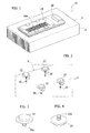
- Various embodiments will now be described, purely by way of non-limiting example, with reference to the accompanying figures, in which:
-
figure 1 schematically shows a lighting system according to embodiments, -
figures 2 to 8 show various components of embodiments, and -
figures 9 to 13 show details of the mounting sequence of embodiments. - In the following description, various specific details aimed at providing a fuller understanding of various exemplary embodiments are explained. The embodiments may be implemented without one or more of the specific details or using other methods, components, materials, etc. In other cases, known structures, materials or operations are not shown or described in detail so that the various aspects of the embodiments may be understood more clearly.
- The reference to "an embodiment" in the context of this description indicates that a particular configuration, structure or feature described in relation to the embodiment is included in at least one embodiment. Therefore, phrases such as "in one embodiment", which may occur at various points in this description, do not necessarily refer to the same embodiment. Moreover, particular forms, structures or features may be combined in any suitable manner in one or more embodiments.
- The reference signs used here are provided solely for the sake of convenience and therefore do not define the scope of protection or ambit of the embodiments.
- In
figure 1 ,reference sign 10 denotes a lighting system (luminaire), for example for streetlighting, in its entirety, which lighting system can be mounted on a pole or on a portal or rather can be suspended on a cable. - The operations for mounting and for electrically connecting such a lighting system (such as the possible positioning of the
system 10 inside a housing for protecting against ambient agents) can be carried out and conducted according to known criteria, and therefore a detailed description is not required at this point. - In various embodiments, the
system 10 can include asupport 12 which, in various embodiments, can be configured as a heat sink and can have a surface S, for example a flat surface, which is suitable for acting as a mounting surface for alighting device 14. - In various embodiments, the
lighting device 14 can in turn include: - a
lighting module 16, formed for example by a planar solid state lighting module including alight radiation source 16a (for example by an array of LEDs mounted on aplanar substrate 16b which resembles a printed circuit board (PCB)), and - a
housing 18 which can frame thelighting module 16 and has awindow 18a therein which makes it possible to expose (allowing the emission of the light radiation externally of the device 10) the light emitting region of themodule 16, that is the region in which thelight radiation source 16a is located. - In various embodiments, the
window 18a can be open or permeable, and therefore the light radiation source (that is the LEDs mounted in theregion 16a) is directly exposed to the outside. - In various embodiments, the
window 18a can be closed by a transparent (that is "permeable to the light radiation") screen, and therefore the light radiation source is exposed to the outside indirectly, through the transparent screen mounted in thewindow 18a. - As can be seen more clearly in
figure 2 , in various embodiments an array ofholes 20, for example threaded holes, for the insertion of fixing screws can be present on the surface S provided for mounting thedevice 14. In various embodiments, theholes 20 can be positioned at positions determined according to the Zhaga standards. - Various embodiments may be based on the principle of not directly screwing the
device 14 onto the surface S, and of realizing the mounting by magnetic means, that is by mounting members on the surface S, at theholes 20, in such a way that thedevice 14, in particular thehousing 18, can be magnetically attractable towards the surface S. - In this way, the
lighting module 16 can be retained applied onto the mounting surface S in that it is sandwiched between the mounting surface S and thehousing 18 magnetically attracted towards the mounting surface S. - In various embodiments, the fixing of the
device 14 on the surface S, instead of being achieved by direct screwing (that is by means of screws which are screwed into theholes 20 and which tighten thedevice 14 against the surface S), can be effected as a magnetic mounting realized on account of members (such as indeed the members 22) screwed into theholes 20. - As can be seen more clearly by observing
figures 2 to 4 , in various embodiments themembers 22 may have a general button-like or token-like (or coin-like) form; in respect of all of this, it is moreover necessary to note that the circular shape shown by way of example in the figures is not in any way imperative for the embodiments: the members can therefore have different shapes, for example polygonal shapes. - In various embodiments, the
members 22 can be screwed into theholes 20 with the aid of a threadedtang 22a. Thetang 22a can therefore be fitted into arespective hole 20 in the surface S and screwed into said hole by acting on themember 22, with a simple manual action - and therefore without having to resort to particular tools - for example until themember 22 rests on the surface S, anchored thereto. -
Figure 5 shows fourmembers 22 fixed in this way onto the surface S. - It will be understood moreover that the presence of four
members 22, screwed into fourholes 20 positioned at the vertices of an ideal square, is shown purely by way of example: the number and the position of theholes 20 and of themembers 22 could indeed be different. Various embodiments can therefore easily adapt toholes 20 of which both the number and the arrangement comply, for example, with Zhaga specifications and/or with different specifications, even of future definition. - In various embodiments, as can be seen more clearly in
figure 6 , thelighting module 16 can have (made, for example, in theplanar substrate 16b) U-shaped notches orincisions 100 located at positions corresponding to the positions of the members 22 (and therefore of the holes 20). In various embodiments, the notches orincisions 100 can be arranged along opposite sides of thesubstrate 16b of themodule 16. - In various embodiments, the
housing 18, of whichfigures 7 and8 provide two perspective views from roughly opposite points of observation, has a general frame-like shape. - In various embodiments,
cavities 24, into whichmembers 26 intended to cooperate with themembers 22 to realize the magnetic attraction force can be inserted, may be present in thehousing 18, for example on the side intended to face towards the surface S and along the outline of thewindow 18a. - In various embodiments, this outcome can be obtained with the aid of
members - To this end, in various embodiments the
members 26 can comprise a magnetized (ferro) magnetic material (for example magnetized plastoferrite or another magnetic material currently used in electrical engineering), so as to generate a magnetic field in order to attract themembers 22, which in turn can comprise a ferromagnetic material which is not magnetized per se (for example soft iron or another suitable material). - This magnetic attraction force ensures that the
housing 18, on which themagnets 26 are mounted, is magnetically attractable towards the surface S, on which themembers 22 are fixed (screwed). - The same outcome can be achieved in a complementary manner, that is with the
members 22 being magnets which attract themembers 26 which act as an anchor, or by realizing both themembers 22 and themembers 26 as mutually attracting magnets. In various embodiments, the relative arrangement of the magnet and of the anchor material attracted thereby can differ from pair to pair ofcomplementary members - Various embodiments can therefore provide that the
housing 18 includes a plurality of magnetically attractive or magnetically attractable members carried by saidhousing 18, preferably at the periphery of the housing, that is along the outline of thewindow 18a. - In various embodiments, the
members 26 can be mounted in thecavities 24 by interference mounting. In various embodiments, themembers 26 can be co-molded directly with thehousing 18, for example when, according to various embodiments, thehousing 18 is made of molded plastic material. -
Figure 9 and those which follow schematically show the sequence for mounting adevice 14 on asupport 12, on which themembers 22 have been mounted pre-emptively (by being screwed into the holes 20). -
Figure 9 shows the possibility of having thelighting module 16 resting on the surface S, which bears thenotches 100 at themembers 22 in such a way that eachnotch 100 embraces arespective member 22. - In various embodiments, the dimensions of the
notches 100 can be chosen so as to be coordinated with the dimensions of themembers 22, so as to ensure that the outlines of thenotches 100 embrace themembers 22 with a certain clearance, thereby avoiding a force fit which is capable of inducing mechanical stresses in thesubstrate 16b of themodule 16. - As shown schematically in
figure 10 , thehousing 18 can be applied from above themodule 16, carrying the cavities 24 (in the inside of which themembers 26 are located) in alignment with the members 22 (in this respect, see the sequence offigures 11 to 13 ). - In various embodiments, the dimensions of the
cavities 24 and/or the shape/dimensions of themembers 22 can be chosen such that themembers 22 can at least partially penetrate into thecavities 24, ensuring exact relative positioning between thehousing 18 and themodule 16. - By way of example, in various embodiments the
members 22 can have anupper portion 22b having smaller radial dimensions than thebase portion 22c facing towards the surface S; for illustrative simplicity, the presence of these two portions, which are clearly identifiable in a number of the accompanying figures, is denoted explicitly byreference signs figure 13 . -
Figure 13 also shows the fact that, in various embodiments, the height or thickness of thebase portions 22c (that is the dimension in a direction orthogonal with respect to the plane of extent of the surface S) of themembers 22 is chosen so as to be at least slightly smaller than the same dimension (that is, in practice, than the thickness) of thesubstrate 16b of themodule 16. - In this way, a gap or interval H is created between the upper circular ring face of the base 22c of the
members 22 and the surface of thehousing 18 facing the latter. In this way, the face of thehousing 18 which faces and is attracted towards the surface S is able to press thesubstrate 16b against the surface S with a constant and uniform pressure so as to optimize the heat exchange during operation. - The assembly sequence shown schematically in
figures 9 to 13 can be reproduced in a contrary way if thehousing 18 is to be removed, for example in order to be able to replace themodule 16, it then being possible to again mount anew module 16 according to the sequence shown here. - The relative operations can be carried out manually, without having to resort to specific tools, it being possible to operate in a simple and easy manner even in the case of
lighting systems 10 which are mounted at a certain height with respect to the ground. - Of course, without affecting the principle of the invention, the constructional details and embodiments may vary, also significantly, with respect to that illustrated here purely by way of non-limiting example, without thereby departing from the scope of protection of the invention. This scope of protection is defined by the accompanying claims.
Claims (10)
- A lighting device (14) for mounting on a mounting surface (S), the device including:- a planar solid state lighting module (16) having a light emitting region (16a),- a housing (18) which frames the lighting module, the housing (18) having a window (18a) therein to expose the light emitting region (16a) of the lighting module (16),wherein the housing (18) is magnetically attractable (22, 26) towards the mounting surface (S) to retain the lighting module (16) applied onto the mounting surface (S) by the lighting module (16) being sandwiched between the mounting surface (S) and the housing (18) magnetically attracted towards the mounting surface (S).
- The device as claimed in claim 1, wherein the housing (18) includes a plurality of magnetically attractive or magnetically attractable members carried by the housing (18), preferably at the periphery of the housing.
- The device as claimed in claim 2, wherein the lighting module (16) includes a flat substrate (16b) having peripheral notches (100) for positioning at said magnetically attractive or magnetically attractable members.
- The device as claimed in any of the preceding claims, wherein the housing (18) is magnetically attractable towards the mounting surface (S) by a plurality of pairs of mutually magnetically attractive members (22, 26), each pair including:- a first member (26) carried by the housing, and- a second member (22) for fixing (22a) to the mounting surface (S).
- The device as claimed in claim 4, wherein the second member (22) in the pair includes a button-like member including a threaded formation (22a) for fixing to the mounting surface by screwing.
- The device as claimed in claim 4 or claim 5, wherein the first member (26) in the pair is located in a cavity (24) in the housing (18), with the second member (22) in the pair at least partly (22b) insertable into the cavity (24).
- The device as claimed in any of claims 4 to 6, wherein one member (26) in the pair is magnetized and acts as an attractive magnet and the other member (22) in the pair is ferromagnetic and acts as an anchor attracted by the magnet.
- The device as claimed in claim 3, in combination with any of claims 4 to 7, wherein the peripheral notches (100) in the flat substrate (16b) are dimensioned to surround with clearance said pairs of magnetically attractive or magnetically attractable members (22, 26).
- A support (12) for mounting a lighting device (14) as claimed in any of claims 1 to 8, wherein the support (12) has a mounting surface (S) provided with fixing cavities (20) for the lighting device (14), said cavities (20) having fixed (20a) therein magnetically attractive or magnetically attractable members (22) to produce magnetic attraction of the housing (18) of the lighting device (14) towards the mounting surface (S).
- A method of mounting onto a mounting surface (S) a planar solid state lighting module (16) having a light emitting region (16a), the method including providing a housing (18) to frame the lighting module (16), the housing (18) having a window (18a) therein to expose the light emitting region (16a) of the lighting module (16), the method including providing said housing (18) as a housing magnetically attractable towards the mounting surface (S) to retain the lighting module (16) applied onto the mounting surface (S) by the lighting module (16) being sandwiched between the mounting surface (S) and the housing (18) magnetically attracted to the mounting surface (S).
Applications Claiming Priority (1)
| Application Number | Priority Date | Filing Date | Title |
|---|---|---|---|
| ITTO20120982 | 2012-11-13 |
Publications (1)
| Publication Number | Publication Date |
|---|---|
| EP2730841A1 true EP2730841A1 (en) | 2014-05-14 |
Family
ID=47522843
Family Applications (1)
| Application Number | Title | Priority Date | Filing Date |
|---|---|---|---|
| EP13192237.9A Withdrawn EP2730841A1 (en) | 2012-11-13 | 2013-11-08 | Lighting device, corresponding support and corresponding method |
Country Status (3)
| Country | Link |
|---|---|
| US (1) | US20140133163A1 (en) |
| EP (1) | EP2730841A1 (en) |
| CN (1) | CN103807670A (en) |
Cited By (2)
| Publication number | Priority date | Publication date | Assignee | Title |
|---|---|---|---|---|
| US20180116196A1 (en) * | 2016-10-31 | 2018-05-03 | Paul Van Kleef | Insect control lighting device |
| US10412953B2 (en) | 2017-02-17 | 2019-09-17 | Clean Concept Llc | Pest control lighting device |
Families Citing this family (2)
| Publication number | Priority date | Publication date | Assignee | Title |
|---|---|---|---|---|
| TWM526777U (en) * | 2015-08-21 | 2016-08-01 | 高準精密工業股份有限公司 | Structure light module with engaging component |
| US10914962B2 (en) * | 2015-08-21 | 2021-02-09 | Everready Precision Ind. Corp | Structured light module with fastening element |
Citations (6)
| Publication number | Priority date | Publication date | Assignee | Title |
|---|---|---|---|---|
| DE202007012249U1 (en) * | 2007-08-31 | 2007-10-25 | Seliger, Roland | Flexible source stone lamp |
| WO2010116301A1 (en) * | 2009-04-08 | 2010-10-14 | Koninklijke Philips Electronics N. V. | Oled luminary with improved mounting means |
| DE102009047489A1 (en) * | 2009-12-04 | 2011-06-09 | Osram Gesellschaft mit beschränkter Haftung | light module |
| US20110304269A1 (en) * | 2010-06-09 | 2011-12-15 | Leader Trend Technology Corp. | Led lamp for easy assembly and fixation |
| EP2481970A2 (en) * | 2011-01-31 | 2012-08-01 | Ceramate Technical Co., Ltd | Magnetic detachable multi-functional led-lamp |
| EP2565955A2 (en) * | 2011-08-30 | 2013-03-06 | Silicon Works Co., Ltd. | Oled tile for illumination |
Family Cites Families (12)
| Publication number | Priority date | Publication date | Assignee | Title |
|---|---|---|---|---|
| US6810612B2 (en) * | 2001-12-11 | 2004-11-02 | Agon-Tech. Corporation | Signboard structure enabling quick and detachable assembling of a face panel thereof |
| EP2122243B1 (en) * | 2007-02-12 | 2016-04-20 | Philips Intellectual Property & Standards GmbH | Modular electric system |
| US20080247160A1 (en) * | 2007-04-04 | 2008-10-09 | Conservation Technology, Llc | Puck light with magnetic cover |
| EP1998105A1 (en) * | 2007-05-29 | 2008-12-03 | Martin Professional A/S | Light fixture with replaceable optics |
| US8187006B2 (en) * | 2009-02-02 | 2012-05-29 | Apex Technologies, Inc | Flexible magnetic interconnects |
| US8651711B2 (en) * | 2009-02-02 | 2014-02-18 | Apex Technologies, Inc. | Modular lighting system and method employing loosely constrained magnetic structures |
| CN201425267Y (en) * | 2009-06-15 | 2010-03-17 | 陈三豹 | Housing of luminaire |
| CN102052591A (en) * | 2009-11-05 | 2011-05-11 | 富士迈半导体精密工业(上海)有限公司 | Solid lighting lamp |
| WO2011083386A1 (en) * | 2010-01-05 | 2011-07-14 | Koninklijke Philips Electronics N.V. | Removable light engine |
| JP5839555B2 (en) * | 2010-11-05 | 2016-01-06 | 株式会社半導体エネルギー研究所 | Lighting device |
| CN202132912U (en) * | 2011-05-24 | 2012-02-01 | 厦门格绿能光电有限公司 | LED (Light-Emitting Diode) radiating module |
| CN202152947U (en) * | 2011-07-28 | 2012-02-29 | 光碁科技股份有限公司 | Non-disposable LED lamp with laminated heat dissipation |
-
2013
- 2013-11-04 US US14/070,611 patent/US20140133163A1/en not_active Abandoned
- 2013-11-08 EP EP13192237.9A patent/EP2730841A1/en not_active Withdrawn
- 2013-11-12 CN CN201310560116.6A patent/CN103807670A/en active Pending
Patent Citations (6)
| Publication number | Priority date | Publication date | Assignee | Title |
|---|---|---|---|---|
| DE202007012249U1 (en) * | 2007-08-31 | 2007-10-25 | Seliger, Roland | Flexible source stone lamp |
| WO2010116301A1 (en) * | 2009-04-08 | 2010-10-14 | Koninklijke Philips Electronics N. V. | Oled luminary with improved mounting means |
| DE102009047489A1 (en) * | 2009-12-04 | 2011-06-09 | Osram Gesellschaft mit beschränkter Haftung | light module |
| US20110304269A1 (en) * | 2010-06-09 | 2011-12-15 | Leader Trend Technology Corp. | Led lamp for easy assembly and fixation |
| EP2481970A2 (en) * | 2011-01-31 | 2012-08-01 | Ceramate Technical Co., Ltd | Magnetic detachable multi-functional led-lamp |
| EP2565955A2 (en) * | 2011-08-30 | 2013-03-06 | Silicon Works Co., Ltd. | Oled tile for illumination |
Cited By (3)
| Publication number | Priority date | Publication date | Assignee | Title |
|---|---|---|---|---|
| US20180116196A1 (en) * | 2016-10-31 | 2018-05-03 | Paul Van Kleef | Insect control lighting device |
| US10337675B2 (en) * | 2016-10-31 | 2019-07-02 | Clean Concept Llc | Insect control lighting device |
| US10412953B2 (en) | 2017-02-17 | 2019-09-17 | Clean Concept Llc | Pest control lighting device |
Also Published As
| Publication number | Publication date |
|---|---|
| US20140133163A1 (en) | 2014-05-15 |
| CN103807670A (en) | 2014-05-21 |
Similar Documents
| Publication | Publication Date | Title |
|---|---|---|
| JP6165832B2 (en) | Line-type lighting device (LINETYPIGHTINGGAPPPARATUS) | |
| JP2017126059A (en) | Display assembly and display including the same | |
| US9188839B2 (en) | Component attachment devices and related systems and methods for machine vision systems | |
| US20140133163A1 (en) | Lighting device, corresponding support and corresponding method | |
| CN101315167A (en) | Light fixture with replaceable optics | |
| US20120218760A1 (en) | Led unit and illumination apparatus using same | |
| US9752737B2 (en) | LED lighting module and luminaire comprising at least one LED lighting module | |
| KR20130018833A (en) | Solid state lighting assembly | |
| US20200292154A1 (en) | Threadless magnetic lightbulb and socket system | |
| CN110418517A (en) | The small light-emitting diode adhesive surface assemble method of display panel | |
| KR20120006859A (en) | Assembly Light Block | |
| KR20090094037A (en) | Device for illuminating means | |
| KR101770629B1 (en) | Assembly for led lamp | |
| KR101635556B1 (en) | Flat lighting device | |
| JP2024098302A (en) | Lighting equipment | |
| CN215061843U (en) | Modular lens and lighting lamp | |
| JP6746411B2 (en) | lighting equipment | |
| US9953550B2 (en) | Scalable illuminated display system | |
| JP2016031857A (en) | lighting equipment | |
| CN216591254U (en) | Illumination module and illumination lamp | |
| CN207298430U (en) | LED lighting module and lighting device | |
| KR100781903B1 (en) | Lighting device using LED module | |
| CN220103006U (en) | Magnetic base | |
| CN215069005U (en) | LED butt joint external member and LED display device | |
| KR20110008248U (en) | Lighting equipment |
Legal Events
| Date | Code | Title | Description |
|---|---|---|---|
| PUAI | Public reference made under article 153(3) epc to a published international application that has entered the european phase |
Free format text: ORIGINAL CODE: 0009012 |
|
| 17P | Request for examination filed |
Effective date: 20131108 |
|
| AK | Designated contracting states |
Kind code of ref document: A1 Designated state(s): AL AT BE BG CH CY CZ DE DK EE ES FI FR GB GR HR HU IE IS IT LI LT LU LV MC MK MT NL NO PL PT RO RS SE SI SK SM TR |
|
| AX | Request for extension of the european patent |
Extension state: BA ME |
|
| R17P | Request for examination filed (corrected) |
Effective date: 20141114 |
|
| RBV | Designated contracting states (corrected) |
Designated state(s): AL AT BE BG CH CY CZ DE DK EE ES FI FR GB GR HR HU IE IS IT LI LT LU LV MC MK MT NL NO PL PT RO RS SE SI SK SM TR |
|
| 17Q | First examination report despatched |
Effective date: 20161207 |
|
| STAA | Information on the status of an ep patent application or granted ep patent |
Free format text: STATUS: THE APPLICATION IS DEEMED TO BE WITHDRAWN |
|
| 18D | Application deemed to be withdrawn |
Effective date: 20170419 |