EP2730498A2 - Joint for composite wings - Google Patents
Joint for composite wings Download PDFInfo
- Publication number
- EP2730498A2 EP2730498A2 EP13192586.9A EP13192586A EP2730498A2 EP 2730498 A2 EP2730498 A2 EP 2730498A2 EP 13192586 A EP13192586 A EP 13192586A EP 2730498 A2 EP2730498 A2 EP 2730498A2
- Authority
- EP
- European Patent Office
- Prior art keywords
- inboard
- outboard
- stringer
- wing
- chord
- Prior art date
- Legal status (The legal status is an assumption and is not a legal conclusion. Google has not performed a legal analysis and makes no representation as to the accuracy of the status listed.)
- Granted
Links
Images



Classifications
-
- B—PERFORMING OPERATIONS; TRANSPORTING
- B64—AIRCRAFT; AVIATION; COSMONAUTICS
- B64C—AEROPLANES; HELICOPTERS
- B64C3/00—Wings
- B64C3/26—Construction, shape, or attachment of separate skins, e.g. panels
-
- B—PERFORMING OPERATIONS; TRANSPORTING
- B64—AIRCRAFT; AVIATION; COSMONAUTICS
- B64C—AEROPLANES; HELICOPTERS
- B64C1/00—Fuselages; Constructional features common to fuselages, wings, stabilising surfaces or the like
- B64C1/26—Attaching the wing or tail units or stabilising surfaces
-
- B—PERFORMING OPERATIONS; TRANSPORTING
- B64—AIRCRAFT; AVIATION; COSMONAUTICS
- B64C—AEROPLANES; HELICOPTERS
- B64C3/00—Wings
- B64C3/18—Spars; Ribs; Stringers
- B64C3/182—Stringers, longerons
-
- B—PERFORMING OPERATIONS; TRANSPORTING
- B64—AIRCRAFT; AVIATION; COSMONAUTICS
- B64C—AEROPLANES; HELICOPTERS
- B64C3/00—Wings
- B64C3/18—Spars; Ribs; Stringers
- B64C3/185—Spars
-
- B—PERFORMING OPERATIONS; TRANSPORTING
- B64—AIRCRAFT; AVIATION; COSMONAUTICS
- B64F—GROUND OR AIRCRAFT-CARRIER-DECK INSTALLATIONS SPECIALLY ADAPTED FOR USE IN CONNECTION WITH AIRCRAFT; DESIGNING, MANUFACTURING, ASSEMBLING, CLEANING, MAINTAINING OR REPAIRING AIRCRAFT, NOT OTHERWISE PROVIDED FOR; HANDLING, TRANSPORTING, TESTING OR INSPECTING AIRCRAFT COMPONENTS, NOT OTHERWISE PROVIDED FOR
- B64F5/00—Designing, manufacturing, assembling, cleaning, maintaining or repairing aircraft, not otherwise provided for; Handling, transporting, testing or inspecting aircraft components, not otherwise provided for
-
- B—PERFORMING OPERATIONS; TRANSPORTING
- B64—AIRCRAFT; AVIATION; COSMONAUTICS
- B64F—GROUND OR AIRCRAFT-CARRIER-DECK INSTALLATIONS SPECIALLY ADAPTED FOR USE IN CONNECTION WITH AIRCRAFT; DESIGNING, MANUFACTURING, ASSEMBLING, CLEANING, MAINTAINING OR REPAIRING AIRCRAFT, NOT OTHERWISE PROVIDED FOR; HANDLING, TRANSPORTING, TESTING OR INSPECTING AIRCRAFT COMPONENTS, NOT OTHERWISE PROVIDED FOR
- B64F5/00—Designing, manufacturing, assembling, cleaning, maintaining or repairing aircraft, not otherwise provided for; Handling, transporting, testing or inspecting aircraft components, not otherwise provided for
- B64F5/10—Manufacturing or assembling aircraft, e.g. jigs therefor
-
- F—MECHANICAL ENGINEERING; LIGHTING; HEATING; WEAPONS; BLASTING
- F16—ENGINEERING ELEMENTS AND UNITS; GENERAL MEASURES FOR PRODUCING AND MAINTAINING EFFECTIVE FUNCTIONING OF MACHINES OR INSTALLATIONS; THERMAL INSULATION IN GENERAL
- F16B—DEVICES FOR FASTENING OR SECURING CONSTRUCTIONAL ELEMENTS OR MACHINE PARTS TOGETHER, e.g. NAILS, BOLTS, CIRCLIPS, CLAMPS, CLIPS OR WEDGES; JOINTS OR JOINTING
- F16B5/00—Joining sheets or plates, e.g. panels, to one another or to strips or bars parallel to them
- F16B5/02—Joining sheets or plates, e.g. panels, to one another or to strips or bars parallel to them by means of fastening members using screw-thread
-
- Y—GENERAL TAGGING OF NEW TECHNOLOGICAL DEVELOPMENTS; GENERAL TAGGING OF CROSS-SECTIONAL TECHNOLOGIES SPANNING OVER SEVERAL SECTIONS OF THE IPC; TECHNICAL SUBJECTS COVERED BY FORMER USPC CROSS-REFERENCE ART COLLECTIONS [XRACs] AND DIGESTS
- Y10—TECHNICAL SUBJECTS COVERED BY FORMER USPC
- Y10T—TECHNICAL SUBJECTS COVERED BY FORMER US CLASSIFICATION
- Y10T29/00—Metal working
- Y10T29/49—Method of mechanical manufacture
- Y10T29/49616—Structural member making
- Y10T29/49622—Vehicular structural member making
Definitions
- the inboard portion of the T-chord may include at least one cutout and the outboard portion of the T-chord may also include at least one cutout.
- a portion of the web of the inboard stringer may extend into the cutout on the inboard portion of the T-chord and a portion of the web of the outboard stringer may extend into the cutout on the outboard portion of the T-chord.
- the inboard and outboard portions of the T-chord may include at least three longitudinal rows of fasteners securing the wing panel assemblies to the T-chord and the splice plate.
- the cutouts on the inboard and outboard portions of the T-chord may extend between fasteners in at least one row of the fasteners.
- the cutouts on the inboard and outboard portions of the T-chord may extend between fasteners in at least two rows of the fasteners.
- the T-chord and splice plate of the joint may be comprised of titanium or aluminum.
- the stringer 60 is bonded to the wing skin 40, 50 to form a wing panel assembly 20, 30.
- the stringer 60 and wing skin 40, 50 may be co-cured so as to form a bond between the two components.
- the wing panel assemblies 20, 30 may then be connected together with T-chord 10 and splice plate 15 to form a wing joint 1.
- the stringer 60 may include a base flange 61 and a web 62. If the stringer 60 is an I stringer, as shown in FIG. 8 , then the stringer 60 may include a cap 63.
- the cap 63 and web 62 of the stringer 60 may be trimmed so that only the base flange 61 of the stringer 60 runs out into the wing joint 1.
- the cap 63 and web 62 may be trimmed to expose a noodle 64 or a plurality of noodles as discussed below.
- An end portion of the inboard wing panel assembly 20 may be positioned between the inboard portion 12 of the T-chord 10 and the inboard portion 16 of the splice plate 15.
- the web 62 and cap 63 may be been trimmed so that only the base flange 61 of the stringer 60, which is bonded to the inboard wing skin 40, is positioned between the T-chord 10 and the splice plate 15.
- the stringer 60 may also include an exposed noodle(s) 64 that is also positioned between the T-chord 10 and the splice plate 15.
- the noodle 64 may be comprised of various materials, such as unidirectional carbon fiber reinforced plastic, laminated carbon fiber reinforced plastic, or glass fiber reinforced plastic. As shown in FIG. 2 , the noodle 64 may not be flush with the base flange 61. If the noodle 64 is not flush with the base flange 61, the T-chord 10 or stringer 60 may be modified to accommodate the non-flush noodle 64, as discussed below.
- FIG. 5A and FIG. 5B show a configuration of T-chord 10 that may be used in the wing joint 1.
- the T-chord 10 may include a scalloped or cutout feature 14 that permits the web 62 of the stringer 60, such as the blade of a blade stringer, to extend between one or more rows of fasteners 80 that connect the T-chord 10 to a spice plate 15.
- the T-chord 10 may include a plurality of rows of fasteners 80.
- the T-chord 10 may include a first row of fasteners 81, a second row of fasteners 82, and a third row of fasteners 83.
- the cutout feature 14 may protrude so it crosses the first and second rows of fasteners 81, 82 as shown in FIG.
- the exposed noodle 64 and base flange 61 may then interface with the bottom of the T-chord 10 when the wing panel assembly 20, the stringer 60 bonded to the wing skin 40, is secured to the T-chord 10 and the splice plate 15, as discussed above.
- exemplary method 100 may include specification and design 104 of the aircraft 102 and material procurement 106.
- component and subassembly manufacturing 108 and system integration 110 of the aircraft 102 takes place.
- the aircraft 102 may go through certification and delivery 112 in order to be placed in service 114.
- routine maintenance and service 116 which may also include modification, reconfiguration, refurbishment, and so on).
- a system integrator may include, without limitation, any number of aircraft manufacturers and major-system subcontractors
- a third party may include, without limitation, any number of vendors, subcontractors, and suppliers
- an operator may be an airline, leasing company, military entity, service organization, and so on.
- the aircraft 102 produced by exemplary method 100 may include an airframe 118 with a plurality of systems 120 and an interior 122.
- high-level systems 120 include one or more of a propulsion system 124, an electrical system 126, a hydraulic system 128, and an environmental system 130. Any number of other systems may be included.
- an aerospace example is shown, the principles of the disclosure may be applied to other industries, such as the automotive industry.
Landscapes
- Engineering & Computer Science (AREA)
- Aviation & Aerospace Engineering (AREA)
- Mechanical Engineering (AREA)
- Manufacturing & Machinery (AREA)
- Transportation (AREA)
- General Engineering & Computer Science (AREA)
- Connection Of Plates (AREA)
- Packages (AREA)
- Slide Fasteners, Snap Fasteners, And Hook Fasteners (AREA)
- Clamps And Clips (AREA)
Abstract
Description
- The configurations described herein relate to a joint for composite wings. The joint may be for a lower side-of-body joint of an aircraft.
- Bolted side-of-body joints may be used to connect wings to the fuselage of an aircraft. One design of a side-of-
body joint 200 presently used to connect a wing to a fuselage is shown inFIG. 12 . The joint 200 includes adouble plus chord 210 that includes avertical portion 211, an upperinboard portion 212, a lowerinboard portion 213, anupper outboard portion 214, and alower outboard portion 215. An inboardwing panel assembly 220 is connected to the inboard side of thedouble plus chord 210 and an outboardwing panel assembly 230 is connected to the outboard side of thedouble plus chord 210. - The inboard
wing panel assembly 220 includes astringer 260 connected to aninboard wing skin 240 and the outboardwing panel assembly 230 includes astringer 260 connected to anoutboard wing skin 250. Thestringer 260 includes abase flange 261 on the bottom of thestringer 260 and acap 263 located on the top with aweb 262 connecting thecap 263 to thebase flange 261. Thebase flange 261 of thestringer 260 is connected to theinboard wing skin 240. Thebase flange 261 may be bonded to theinboard wing skin 240. - The
cap 263 is connected to the upperinboard portion 212 of thedouble plus chord 210 by a plurality offasteners 281. A portion of theweb 262 andbase flange 261 of thestringer 260 is cut so thatbase flange 261 of thestringer 260 does not overlap the lowerinboard portion 213 of thedouble plus chord 210. Aradius filler plate 291 is positioned above thebase flange 261.Fasteners 290 connect theradius filler plate 291 to thebase flange 261 and theinboard wing skin 240, which clamp theinboard wing skin 240 andbase flange 261 to form a crack arrestment mechanism. Only theinboard wing skin 240 of the inboardwing panel assembly 220 is positioned below the lowerinboard portion 213 of thedouble plus chord 210. Theinboard wing skin 240 is positioned between the lowerinboard portion 213 of thedouble plus chord 210 and asplice plate 270.Fasteners 280 connect thesplice plate 270 to the lowerinboard portion 213 of thedouble plus chord 210 securing theinboard wing skin 240 to thejoint 200. - The outboard
wing panel assembly 230 is constructed the same way as the inboardwing panel assembly 220.Fasteners 281 are used to connect thecap 263 of thestringer 260 to theupper outboard portion 214 of thedouble plus chord 210.Fasteners 280 connect theoutboard wing skin 250 to thesplice plate 270 and thelower outboard portion 215 of thedouble plus chord 210. The connection of one portion of a wing panel assembly to a first portion of a joint, and the connection of a second portion of a wing panel assembly to a second portion of the joint may result in differing forces to be applied to the different portions of the assembly. - In view of the foregoing, there exists a need in the art for a side-of-body joint that secures both portions of a wing panel assembly with a clamping configuration having a single interface.
- It may be beneficial to provide a joint that secures both portions of a wing panel assembly with a clamping configuration having a single interface.
- One configuration is a wing joint comprising a T-chord, a splice plate, an inboard wing panel assembly, and an outboard wing panel assembly. The T-chord includes an inboard portion, an outboard portion, and a vertical portion. The splice plate has an inboard portion and an outboard portion. The wing joint includes at least one inboard stringer connected, such as being bonded, to the inboard wing skin to form an inboard wing panel assembly and at least one outboard stringer connected, such as being bonded, to the outboard wing skin to form an outboard wing panel assembly. A portion of the inboard wing panel assembly is positioned between the inboard portion of the T-chord and the inboard portion of the splice plate. A portion of the outboard wing panel assembly is positioned between the outboard portion of the T-chord and the outboard portion of the splice plate. A first plurality of fasteners connect the inboard portion of the T-chord with the inboard portion of the splice plate to secure the inboard wing panel assembly to the T-chord and the splice plate. A second plurality of fasteners connect the outboard portion of the T-chord with the outboard portion of the splice plate to secure the outboard wing panel assembly to the T-chord and the splice plate.
- The outboard stringer and inboard stringer of the wing joint may each include a base flange, at least one web, and at least one noodle. The outboard stringer and inboard stringer may be blade stringers. The outboard stringer and inboard stringer may be I stringers. The I stringers may include a cap. The inboard stringer and outboard stringer may each be trimmed to expose at least one noodle. The inboard wing panel assembly may comprise a portion of an inboard wing skin, a portion of a base flange of an inboard stringer, and a portion of at least one exposed noodle. The outboard wing panel assembly may comprise a portion of an outboard wing skin, a portion of a base flange of an outboard stringer, and a portion of at least one exposed noodle.
- The T-chord of the joint may include a first groove in the inboard portion to accommodate at least one exposed noodle of an inboard stringer and a second groove in the outboard portion to accommodate at least one exposed noodle of an outboard stringer. The joint may include a first shim positioned between the base flange of an inboard stringer and the inboard portion of the T-chord and a second shim positioned between the base flange of the outboard stringer and the outboard portion of the T-chord. The first and second shims may be positioned adjacent to at least one exposed noodle. The joint may be a lower side-of-body joint for a composite wing assembly.
- The inboard portion of the T-chord may include at least one cutout and the outboard portion of the T-chord may also include at least one cutout. A portion of the web of the inboard stringer may extend into the cutout on the inboard portion of the T-chord and a portion of the web of the outboard stringer may extend into the cutout on the outboard portion of the T-chord. The inboard and outboard portions of the T-chord may include at least three longitudinal rows of fasteners securing the wing panel assemblies to the T-chord and the splice plate. The cutouts on the inboard and outboard portions of the T-chord may extend between fasteners in at least one row of the fasteners. The cutouts on the inboard and outboard portions of the T-chord may extend between fasteners in at least two rows of the fasteners. The T-chord and splice plate of the joint may be comprised of titanium or aluminum.
- One configuration is a method of forming a wing joint. The method comprises forming an inboard wing panel assembly and forming an outboard wing panel assembly. The inboard wing panel assembly comprises at least one inboard stringer connected to an inboard wing skin, the stringer including a base flange, at least one web, and at least one noodle. The outboard wing panel assembly comprises at least one outboard stringer connected to an outboard wing skin, the stringer including a base flange, at least one web, and at least one noodle. The method includes trimming the web of the inboard stringer to expose at least one noodle and trimming the web of the outboard stringer to expose at least one noodle. The method includes positioning a portion of the inboard wing panel assembly between an inboard portion of a T-chord and an inboard portion of a splice plate and securing the inboard wing panel assembly to the T-chord and splice plate with a plurality of fasteners. The portion of the inboard wing panel assembly including a portion of the inboard wing skin, a portion of the base flange of the inboard stringer, and at least one exposed noodle. The method includes positioning a portion of the outboard wing panel assembly between an outboard portion of a T-chord and an outboard portion of a splice plate and securing the outboard wing panel assembly to the T-chord and splice plate with a plurality of fasteners. The portion of the outboard wing panel assembly including a portion of the outboard wing skin, a portion of the base flange of the outboard stringer, and at least one exposed noodle.
- The method may include providing a groove in the inboard portion of the T-chord to accommodate at least one exposed noodle of the inboard stringer and providing a groove in the outboard portion of the T-chord to accommodate at least one exposed noodle of the outboard stringer. The method may include providing at least a first shim positioned between the inboard wing panel assembly and the inboard portion of the T-chord and providing at least a second shim positioned between the outboard wing panel assembly and the outboard portion of the T-chord. The shims may be positioned adjacent to at least one exposed noodle.
- The stringers or the method may be composite materials comprised of a plurality of plies. The method may include adding additional sacrificial plies to the stringers prior to forming the wing panel assemblies, the sacrificial plies permitting the removal of at least a portion of the sacrificial plies to provide that an exposed noodle is flush without reducing the load bearing capability of the wing panel assemblies. The forming an inboard wing panel assembly may further comprise co-curing the inboard wing skin and the inboard stringer and forming an outboard wing panel assembly may further comprise co-curing the outboard wing skin and the outboard stringer. The forming an inboard wing panel assembly may further comprise co-bonding the inboard wing skin and the inboard stringer and forming an outboard wing panel assembly may further comprise co-bonding the outboard wing skin and the outboard stringer.
- One configuration is a wing joint that comprises a first clamp plate, a second clamp plate, and a wing panel assembly. The wing panel assembly is comprised of a stringer bonded to a wing skin. A portion of the wing panel assembly is secured between the first clamp plate and the second clamp plate. The stringer of the wing panel assembly has been trimmed to expose a noodle, which is part of the portion of the wing panel assembly secured between the first clamp plate and the second clamp plate.
-
-
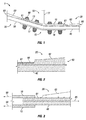
FIG. 1 shows a configuration of a joint for a composite wing; -
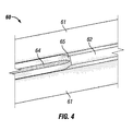
FIG. 2 shows a partial cross-section of a stringer bonded to a wing skin to form a wing panel assembly to be used with a configuration of a joint for a composite wing; -
FIG. 3 shows a schematic showing the potential forces on a configuration of a joint for a composite wing; -
FIG. 4 shows a portion of a stringer that has been trimmed for use with a configuration of a joint for a composite wing; -
FIG. 5A shows a top view of a configuration of a joint for a composite wing; -
FIG. 5B shows a perspective view a configuration of a joint for a composite wing; -
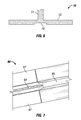
FIG. 6 shows a configuration of a T-chord that includes a groove to accommodate non-flush exposed noodles of a stringer; -
FIG. 7 shows a portion of one configuration of a trimmed stringer for use with a configuration of a joint for a composite wing with shims being positioned adjacent to a non-flush exposed noodle of a stringer; -
FIG. 8 shows an I stringer that may be used with the disclosed wing joint; -
FIG. 9 shows a blade stringer having sacrificial plies that may be used with the disclosed wing joint; -
FIG. 10 is a flow diagram of aircraft production and service methodology in accordance with an advantageous configuration; -
FIG. 11 is a block diagram of an aircraft in accordance with an advantageous configuration; and -
FIG. 12 shows a prior art joint for a composite wing. - While the disclosure is susceptible to various modifications and alternative forms, specific configurations have been shown by way of example in the drawings and will be described in detail herein. However, it should be understood that the disclosure is not intended to be limited to the particular forms disclosed. Rather, the intention is to cover all modifications, equivalents and alternatives falling within the scope of the disclosure as defined by the appended claims.
-
FIG. 1 shows a configuration of a wing joint 1. The wing joint 1 includes afirst clamp plate 10 and asecond clamp plate 15 used together to secure an inboardwing panel assembly 20 and an outboardwing panel assembly 30. Thefirst clamp plate 10 may be a T-chord and the second clamp plate may be a splice plate. Hereinafter, the first clamp plate will be referred to as a T-chord 10 and the second clamp plate will be referred to as asplice plate 15. The T-chord 10 includes avertical portion 11, aninboard portion 12, and anoutboard portion 13. Thesplice plate 15 includes aninboard portion 16 and anoutboard portion 17. The T-chord 10 andsplice plate 15 are used to connect together an inboardwing panel assembly 20 and an outboardwing panel assembly 30. - The inboard
wing panel assembly 20 is comprised of aninboard wing skin 40 and astringer 60. Theinboard wing skin 40 and thestringer 60 may both be comprised of a composite material, which may be comprised of multiple layers of a material bonded and/or cured together. The material may be comprised of various materials used in the formation of composite materials. One example of such material is carbon fiber reinforced plastic. Likewise, the outboardwing panel assembly 30 is comprised of anoutboard wing skin 50 and astringer 60. As discussed above, theoutboard wing skin 50 and thestringer 60 may also be co-bonded or co-cured. Thestringer 60 used may be various stringers used to strengthen composite parts, such as an I stringer or a blade stringer. - The
stringer 60 is bonded to thewing skin wing panel assembly stringer 60 andwing skin wing panel assemblies wing panel assemblies chord 10 andsplice plate 15 to form a wing joint 1. Thestringer 60 may include abase flange 61 and aweb 62. If thestringer 60 is an I stringer, as shown inFIG. 8 , then thestringer 60 may include acap 63. Thecap 63 andweb 62 of thestringer 60 may be trimmed so that only thebase flange 61 of thestringer 60 runs out into the wing joint 1. Thecap 63 andweb 62 may be trimmed to expose anoodle 64 or a plurality of noodles as discussed below. - An end portion of the inboard
wing panel assembly 20 may be positioned between theinboard portion 12 of the T-chord 10 and theinboard portion 16 of thesplice plate 15. As discussed above, theweb 62 andcap 63 may be been trimmed so that only thebase flange 61 of thestringer 60, which is bonded to theinboard wing skin 40, is positioned between the T-chord 10 and thesplice plate 15. As discussed below, thestringer 60 may also include an exposed noodle(s) 64 that is also positioned between the T-chord 10 and thesplice plate 15. A plurality offasteners 80 connect theinboard portion 12 of the T-chord 10 to theinboard portion 16 of thesplice plate 15, securing the inboardwing panel assembly 20 to the wing joint 1. Likewise, the outboardwing panel assembly 30 is connected to theoutboard portion 13 of the T-chord 10 and theoutboard portion 17 of thesplice plate 15. -
FIG. 2 shows a partial cross-section of awing panel assembly 20 that includes astringer 60 bonded to awing skin 40. Theweb 62 andcap 63 have been trimmed to expose anoodle 64 on thebase flange 61 of thestringer 60.Noodles 64 are typically unidirectional fibers that are used to fill a junction between portions of astringer 60 as shown inFIG. 8 . For example, an I stringer may be comprised of two "c" shaped brackets connected together back to back. A void may exist at both the top and bottom junctions where the back of the brackets meet. Anoodle 64, which may be a unidirectional fiber, may be used to fill the void. Thenoodle 64 may be comprised of various materials, such as unidirectional carbon fiber reinforced plastic, laminated carbon fiber reinforced plastic, or glass fiber reinforced plastic. As shown inFIG. 2 , thenoodle 64 may not be flush with thebase flange 61. If thenoodle 64 is not flush with thebase flange 61, the T-chord 10 orstringer 60 may be modified to accommodate thenon-flush noodle 64, as discussed below. -
FIG. 3 is a schematic showing the potential forces that may be applied to the wing joint 1. As both theinboard wing skin 40 andbase flange 61 are secured to the T-chord 10 and thesplice plate 15 at the same interface, the same tension force is applied to both components equally as shown byarrow 85. Further, the tension forces (arrows 90) on both the T-chord 10 andsplice plate 15 are substantially equal and in the same direction, because the two components provide a single interface for capturing thewing panel assembly 20 in comparison to the multiple interfaces of thedouble plus chord 210 shown inFIG. 12 . -
FIG. 4 shows a portion of astringer 60 that may be connected to the wing joint 1 of the present disclosure. Thestringer 60 includes abase flange 61 andweb 62 trimmed to expose anoodle 64. Thestringer 60 may include a web and cap run out 65 where the trimmedweb 62 interfaces with the exposednoodle 64. As discussed above, thenoodle 64 may be comprised of unidirectional fiber and may fill a void between two interfaces in thestringer 60. -
FIG. 5A and FIG. 5B show a configuration of T-chord 10 that may be used in the wing joint 1. The T-chord 10 may include a scalloped orcutout feature 14 that permits theweb 62 of thestringer 60, such as the blade of a blade stringer, to extend between one or more rows offasteners 80 that connect the T-chord 10 to aspice plate 15. The T-chord 10 may include a plurality of rows offasteners 80. For example, the T-chord 10 may include a first row offasteners 81, a second row offasteners 82, and a third row offasteners 83. Thecutout feature 14 may protrude so it crosses the first and second rows offasteners FIG. 5A and FIG. 5B . The T-chord 10 may include a plurality of cutout features 14. The use of thecutout feature 14 of the T-chord 10 may permit thestringer 60 to be more robust by permitting a longer length ofweb 62 along thestringer 60. The number and orientation of the cutout features 14 is for illustrative purposes only. The configuration, depth, and location of the cutout features 14, as well as the number of rows and configuration of fasteners, may be varied as would be appreciated by one of ordinary skill in the art having the benefit of this disclosure. For example, even the individual length of the cutout features 14 may be varied within a single T-chord 10. -
FIG. 6 shows a partial cross-section of a configuration of T-chord 10 that includes at least onegroove 18 on the bottom side of theinboard portion 12 of the T-chord 10. Thegroove 18 may be adapted to accommodate anon-flush noodle 64 present on thewing panel assemblies non-flush noodle 64 into thegroove 18 may enable the interface between the T-chord 10 andwing panel assembly 20 to be flush. The T-chord 10 may include a plurality ofgrooves 18 in the bottom of both the inboard 12 and outboard 13 portions to accommodate a plurality of exposednoodles 64. -
FIG. 7 shows a configuration of a trimmedstringer 60 that includesshims 67 to accommodate fornon-flush noodles 64. The shim(s) 67 are located adjacent to thenon-flush noodle 64 between thebase flange 61 and the T-chord 10. Theshims 67 fill the gaps between thewing panel assembly chord 10 due to thenoodle 64 being non-flush. Theshims 67 are shown for illustrative purposes only as the shape, number, and configuration of theshims 67 may be varied, as would be appreciated by one of ordinary skill in the art having the benefit of this disclosure. -
FIG. 8 shows a cross-section of anI stringer 60 bonded to awing skin 40. TheI stringer 60 includes abase flange 61, aweb 62, and acap 63. For co-bonded wing panels, thebase flange 61 may include abase flange charge 66, which is not required for co-cured wing panels. Thecap 63 may include acap charge 68 for both co-bonded and co-cured wing panels. As shown,noodles 64 fill the gap between theweb 62 and thecap 63 as well as the gap between theweb 62 and thebase flange 61. As discussed above, thecap 63 andweb 62 may be trimmed on one end of thestringer 60 to expose thenoodle 64. The exposednoodle 64 andbase flange 61 may then interface with the bottom of the T-chord 10 when thewing panel assembly 20, thestringer 60 bonded to thewing skin 40, is secured to the T-chord 10 and thesplice plate 15, as discussed above. -
FIG. 9 shows a cross-section of ablade stringer 60 that includes additional plies or layers, referred to herein assacrificial plies 69, that permit the removal of material from thestringer 60 while maintaining the desired structural integrity of thestringer 60. As discussed above, theweb 62 of thestringer 60 is trimmed to expose thenoodle 64 and provide an interface between thestringer 60 and the T-chord 10. Upon exposing thenoodle 64, thenoodle 64 may not be flush with thebase flange 61. To accommodate for a potentialnon-flush noodle 64,sacrificial plies 69 are added to theweb 62 andbase flange 61 of thestringer 60. The sacrificial plies permit theweb 62 andbase flange 61 to be trimmed down to alevel 70, which is flush with the exposednoodle 64 while retaining a thickness of material of thestringer 60 that maintains its intended structural integrity. - Referring more particularly to the drawings, configurations of the disclosure may be described in the context of an aircraft manufacturing and
service method 100 as shown inFIG. 10 and anaircraft 102 as shown inFIG. 11 . During pre-production,exemplary method 100 may include specification anddesign 104 of theaircraft 102 andmaterial procurement 106. During production, component andsubassembly manufacturing 108 andsystem integration 110 of theaircraft 102 takes place. Thereafter, theaircraft 102 may go through certification anddelivery 112 in order to be placed inservice 114. While inservice 114 by a customer, theaircraft 102 is scheduled for routine maintenance and service 116 (which may also include modification, reconfiguration, refurbishment, and so on). - Each of the processes of
exemplary method 100 may be performed or carried out by a system integrator, a third party, and/or an operator (e.g., a customer). For the purposes of this description, a system integrator may include, without limitation, any number of aircraft manufacturers and major-system subcontractors; a third party may include, without limitation, any number of vendors, subcontractors, and suppliers; and an operator may be an airline, leasing company, military entity, service organization, and so on. - As shown in
FIG. 11 , theaircraft 102 produced byexemplary method 100 may include anairframe 118 with a plurality ofsystems 120 and an interior 122. Examples of high-level systems 120 include one or more of apropulsion system 124, anelectrical system 126, ahydraulic system 128, and anenvironmental system 130. Any number of other systems may be included. Although an aerospace example is shown, the principles of the disclosure may be applied to other industries, such as the automotive industry. - Apparatus and method embodied herein may be employed during any one or more of the stages of the aircraft manufacturing and
service method 100. For example, components or subassemblies corresponding toproduction process 108 may be fabricated or manufactured in a manner similar to components or subassemblies produced while theaircraft 102 is inservice 114. Also, one or more apparatus configurations, method configurations, or a combination thereof may be utilized during the production processes 108 and 110, for example, by expediting assembly of or reducing the cost of anaircraft 102. Similarly, one or more of apparatus configurations, method configurations, or a combination thereof may be utilized while theaircraft 102 is inservice 114, for example and without limitation, to maintenance andservice 116. - Further, the disclosure comprises embodiments according to the following clauses:
- A. A wing joint comprising: a T-chord having an inboard portion, an outboard portion, and a vertical portion; a splice plate having an inboard portion and an outboard portion; an inboard wing skin; an outboard wing skin; at least one inboard stringer connected to the inboard wing skin to form an inboard wing panel assembly, a portion of the inboard wing panel assembly positioned between the inboard portion of the T-chord and the inboard portion of the splice plate; a first plurality of fasteners connecting the inboard portion of the T-chord with the inboard portion of the splice plate to secure the inboard wing panel assembly to the T-chord and the splice plate; at least one outboard stringer connected to the outboard wing skin to form an outboard wing panel assembly, a portion of the outboard wing panel assembly positioned between the outboard portion of the T-chord and the outboard portion of the splice plate; and a second plurality of fasteners connecting the outboard portion of the T-chord with the outboard portion of the splice plate to secure the outboard wing panel assembly to the T-chord and the splice plate.
- B. The wing joint of clause A, wherein the joint is a lower side-of-body joint for a composite wing assembly.
- C. The wing joint of clause A, the outboard stringer and the inboard stringer each comprising a base flange, at least one web, and at least one noodle.
- D. The wing joint of clause C, the outboard stringer and the inboard stringer being blade stringers.
- E. The wing joint of clause C, the inboard portion of the T-chord comprising at least one cutout and the outboard portion of the T-chord comprising at least one cutout, a portion of the web of the inboard stringer extending into the cutout on the inboard portion the T-chord and a portion of the web of the outboard stringer extending into the cutout on the outboard portion of the T-chord.
- F. The wing joint of clause E, the first and second plurality of fasteners each comprising at least three longitudinal rows of fasteners, the at least one cutout on the inboard portion extending between fasteners in at least one row of fasteners and the at least one cutout on the outboard portion extending between fasteners in at least one row of fasteners.
- G. The wing joint of clause E, the first and second plurality of fasteners each comprising at least three longitudinal rows of fasteners, the at least one cutout on the inboard portion extending between fasteners in at least two rows of fasteners and the at least one cutout on the outboard portion extending between fasteners in at least two rows of fasteners.
- H. The wing joint of clause C, the outboard stringer and the inboard stringer being I stringers.
- 1. The wing joint of clause H, the I stringers further comprising a cap.
- J. The wing joint of clause C, the outboard stringer and the inboard stringer each being trimmed to expose the at least one noodle.
- K. The wing joint of clause J, wherein the inboard wing panel assembly comprises a portion of the inboard wing skin, a portion of the base flange of the inboard stringer, and a portion of the at least one exposed noodle of the inboard stringer and wherein the outboard wing panel assembly comprises a portion of the outboard wing skin, a portion of the base flange of the outboard stringer, and a portion of the at least one exposed noodle of the outboard stringer.
- L. The wing joint of clause K, the T-chord further comprising a first groove in the inboard portion to accommodate the at least one exposed noodle of the inboard stringer and a second groove in the outboard portion to accommodate the at least one exposed noodle of the outboard stringer.
- M. The wing joint of clause K, further comprising a first shim and a second shim, the first shim positioned between the base flange of the inboard stringer and the inboard portion of the T-chord, the first shim being adjacent to at least one exposed noodle of the inboard stringer, the second shim positioned between the base flange of the outboard stringer and the outboard portion of the T-chord, the second shim being adjacent to at least one exposed noodle of the outboard stringer.
- N. A method of forming a wing joint, the method comprising: forming an inboard wing panel assembly, the inboard wing panel assembly comprising at least one inboard stringer connected to an inboard wing skin, the at least one inboard stringer comprising a base flange, at least one web, and at least one noodle; forming an outboard wing panel assembly, the outboard wing panel assembly comprising at least one outboard stringer connected to an outboard wing skin, the at least one outboard stringer comprising a base flange, at least one web, and at least one noodle; trimming the at least one web of the inboard stringer to expose the at least one noodle; trimming the at least one web of the outboard stringer to expose the at least one noodle; positioning a portion of the inboard wing panel assembly between an inboard portion of a T-chord and an inboard portion of a splice plate, the portion of the inboard wing panel assembly including a portion of the inboard wing skin, a portion of the base flange of the inboard stringer, and the at least one exposed noodle of the inboard stringer; securing the inboard wing panel assembly to the inboard portion of the T-chord and the inboard portion of the splice plate with a plurality of fasteners; positioning a portion of the outboard wing panel assembly between an outboard portion of a T-chord and an outboard portion of a splice plate, the portion of the outboard wing panel assembly including a portion of the outboard wing skin, a portion of the base flange of the outboard stringer, and the at least one exposed noodle of the outboard stringer; and securing the outboard wing panel assembly to the outboard portion of the T-chord and the outboard portion of the splice plate with a plurality of fasteners.
- O. The method of clause N further comprising: providing a groove in the inboard portion of the T-chord to accommodate the at least one exposed noodle of the inboard stringer; and providing a groove in the outboard portion of the T-chord to accommodate the at least one exposed noodle of the outboard stringer.
- P. The method of clause N further comprising: providing at least a first shim positioned between the inboard wing panel assembly and the inboard portion of the T-chord, the first shim being adjacent to the at least one exposed noodle of the inboard stringer; and providing at least a second shim positioned between the outboard wing panel assembly and the outboard portion of the T-chord, the second shim being adjacent to the at least one exposed noodle of the outboard stringer.
- Q. The method of clause N, wherein forming an inboard wing panel assembly further comprises co-curing the inboard wing skin and the inboard stringer and wherein forming an outboard wing panel assembly further comprises co-curing the outboard wing skin and the outboard stringer.
- R. The method of clause N, wherein forming an inboard wing panel assembly further comprises co-bonding the inboard wing skin and the inboard stringer and wherein forming an outboard wing panel assembly further comprises co-bonding the outboard wing skin and the outboard stringer.
- S. The method of clause N, wherein the stringers are composite materials comprised of a plurality of plies.
- T. The method of clause S further comprising: adding additional sacrificial plies to the inboard stringer and the outboard stringer prior to forming the inboard wing panel assembly and prior to forming the outboard wing panel assembly, the additional sacrificial plies permitting removal of the sacrificial plies to provide that the exposed noodle is flush without reducing a load bearing capability of the inboard and outboard wing panel assemblies.
- U. A wing joint comprising: a first clamp plate; a second clamp plate; and a wing panel assembly, the wing panel assembly comprised of a stringer connected to a wing skin, a portion of the wing panel assembly being secured between the first clamp plate and the second clamp plate, wherein the stringer of the portion of the wing panel assembly secured between the first clamp plate and second clamp plate is trimmed to expose a noodle.
- Although this disclosure has been described in terms of certain preferred configurations, other configurations that are apparent to those of ordinary skill in the art, including configurations that do not provide all of the features and advantages set forth herein, are also within the scope of this disclosure. Accordingly, the scope of the present disclosure is defined only by reference to the appended claims and equivalents thereof.
-
- 1
- wing joint
- 10
- T-chord
- 11
- vertical portion of T-chord
- 12
- inboard portion of T-chord
- 13
- outboard portion of T-chord
- 14
- cutout feature in T-chord
- 15
- splice plate
- 16
- inboard portion of splice plate
- 17
- outboard portion of splice plate
- 18
- grooves in T-chord
- 20
- inboard wing panel assembly
- 30
- outboard wing panel assembly
- 40
- inboard wing skin
- 50
- outboard wing skin
- 60
- stringer
- 61
- base flange
- 62
- web
- 63
- cap
- 64
- noodle
- 65
- cap and web run out
- 66
- base flange charge
- 67
- shim
- 68
- cap charge
- 69
- sacrificial plies
- 70
- trimmed level
- 80
- fastener
- 81
- first row of fasteners
- 82
- second row of fasteners
- 83
- third row of fasteners
- 85
- tension force on wing panel assembly
- 90
- tension force on T-chord and splice plate
- 200
- prior art wing joint
- 210
- double plus chord
- 211
- vertical portion of double plus chord
- 212
- upper inboard portion of double plus chord
- 213
- lower inboard portion of double plus chord
- 214
- upper outboard portion of double plus chord
- 215
- lower outboard portion of double plus chord
- 220
- inboard wing panel assembly
- 230
- outboard wing panel assembly
- 240
- inboard wing skin
- 250
- outboard wing skin
- 260
- stringer
- 261
- stringer base flange
- 262
- stringer web
- 263
- stringer cap
- 270
- splice plate
- 280
- fastener
- 281
- fastener
- 282
- fastener
- 291
- radius filler
Claims (15)
- A wing joint (1) comprising:a T-chord (10) having an inboard portion (12), an outboard portion (13), and a vertical portion (11);a splice plate (15) having an inboard portion (16) and an outboard portion (17);an inboard wing skin (40);an outboard wing skin (50);at least one inboard stringer (60) connected to the inboard wing skin (40) to form an inboard wing panel assembly (20), a portion of the inboard wing panel assembly (20) positioned between the inboard portion of the T-chord (12) and the inboard portion of the splice plate (16);a first plurality of fasteners (80) connecting the inboard portion of the T-chord (12) with the inboard portion of the splice plate (16) to secure the inboard wing panel assembly (20) to the T-chord (10) and the splice plate (15);at least one outboard stringer (60) connected to the outboard wing skin (50) to form an outboard wing panel assembly (30), a portion of the outboard wing panel assembly (30) positioned between the outboard portion of the T-chord (13) and the outboard portion of the splice plate (17); anda second plurality of fasteners (80) connecting the outboard portion of the T-chord (13) with the outboard portion of the splice plate (17) to secure the outboard wing panel assembly (30) to the T-chord (10) and the splice plate (15).
- The wing joint (1) of claim 1, wherein the joint (1) is a lower side-of-body joint for a composite wing assembly.
- The wing joint (1) of any preceding claim, wherein the outboard stringer (60) and the inboard stringer (60) are blade stringers, each comprising a base flange (61), at least one web (62), and at least one noodle (64).
- The wing joint (1) of any preceding claim, the inboard portion of the T-chord (12) comprising at least one cutout (14) and the outboard portion of the T-chord (13) comprising at least one cutout (14), a portion of a web (62) of the inboard stringer (60) extending into the cutout (14) on the inboard portion the T-chord (12) and a portion of a web (62) of the outboard stringer (60) extending into the cutout (14) on the outboard portion of the T-chord (13).
- The wing joint (1) of any preceding claim, the first and second plurality of fasteners (80) each comprising at least three longitudinal rows of fasteners (81, 82, 83), wherein at least one cutout (14) on the inboard portion of the T-chord (12) extends between fasteners (80) in at least one row of fasteners (80) and at least one cutout (14) on the outboard portion of the T-chord (13) extends between fasteners (80) in at least one row of fasteners (80).
- The wing joint (1) of any preceding claim, the first and second plurality of fasteners (80) each comprising at least three longitudinal rows of fasteners (81, 82, 83), wherein at least one cutout (14) on the inboard portion of the T-chord (12) extends between fasteners (80) in at least two rows of fasteners (80) and at least one cutout (14) on the outboard portion of the T-chord (13) extends between fasteners (80) in at least two rows of fasteners (80).
- The wing joint (1) of any preceding claim, wherein the outboard stringer (60) and the inboard stringer (60) are I stringers, each having a cap (63).
- The wing joint (1) of any preceding claim, wherein the outboard stringer (60) and the inboard stringer (60) each comprise at least one noodle (64), the outboard stringer (60) and the inboard stringer (60) each being trimmed to expose the at least one noodle (64).
- The wing joint (1) of any preceding claim, wherein the inboard wing panel assembly (20) comprises a portion of the inboard wing skin (40), a portion of a base flange (61) of the inboard stringer (60), and a portion of at least one exposed noodle (64) of the inboard stringer (60) and wherein the outboard wing panel assembly (30) comprises a portion of the outboard wing skin (50), a portion of a base flange (61) of the outboard stringer (60), and a portion of at least one exposed noodle (64) of the outboard stringer (60), wherein the T-chord (10) further comprises a first groove (18) in the inboard portion (12) to accommodate the at least one exposed noodle (64) of the inboard stringer (60) and a second groove (18) in the outboard portion (13) to accommodate the at least one exposed noodle (64) of the outboard stringer (60), and further comprising a first shim (67) and a second shim (67), the first shim (67) positioned between the base flange (61) of the inboard stringer (60) and the inboard portion of the T-chord (12), the first shim (67) being adjacent to at least one exposed noodle (64) of the inboard stringer (60), the second shim (67) positioned between the base flange (61) of the outboard stringer (60) and the outboard portion of the T-chord (13), the second shim (67) being adjacent to at least one exposed noodle (64) of the outboard stringer (60).
- A method of forming a wing joint (1), the method comprising:forming an inboard wing panel assembly (20), the inboard wing panel assembly (20) comprising at least one inboard stringer (60) connected to an inboard wing skin (40), the at least one inboard stringer (60) comprising a base flange (61), at least one web (62), and at least one noodle (64);forming an outboard wing panel assembly (30), the outboard wing panel assembly (30) comprising at least one outboard stringer (60) connected to an outboard wing skin (50), the at least one outboard stringer (60) comprising a base flange (61), at least one web (62), and at least one noodle (64);trimming the at least one web (62) of the inboard stringer (60) to expose the at least one noodle (64);trimming the at least one web (62) of the outboard stringer (60) to expose the at least one noodle (64);positioning a portion of the inboard wing panel assembly (20) between an inboard portion of a T-chord (12) and an inboard portion of a splice plate (16), the portion of the inboard wing panel assembly (20) including a portion of the inboard wing skin (40), a portion of the base flange (61) of the inboard stringer (60), and the at least one exposed noodle (64) of the inboard stringer (60);securing the inboard wing panel assembly (20) to the inboard portion of the T-chord (12) and the inboard portion of the splice plate (16) with a plurality of fasteners (80);positioning a portion of the outboard wing panel assembly (30) between an outboard portion of a T-chord (13) and an outboard portion of a splice plate (17), the portion of the outboard wing panel assembly (30) including a portion of the outboard wing skin (50), a portion of the base flange (61) of the outboard stringer (60), and the at least one exposed noodle (64) of the outboard stringer (60); andsecuring the outboard wing panel assembly (30) to the outboard portion of the T-chord (13) and the outboard portion of the splice plate (17) with a plurality of fasteners (80).
- The method of claim 10 further comprising:providing a groove (18) in the inboard portion of the T-chord (12) to accommodate the at least one exposed noodle (64) of the inboard stringer (60); andproviding a groove (18) in the outboard portion of the T-chord (13) to accommodate the at least one exposed noodle (64) of the outboard stringer (60).
- The method of any of claims 10 to 11 further comprising:providing at least a first shim (67) positioned between the inboard wing panel assembly (20) and the inboard portion of the T-chord (12), the first shim (67) being adjacent to the at least one exposed noodle (64) of the inboard stringer (60); andproviding at least a second shim (67) positioned between the outboard wing panel assembly (30) and the outboard portion of the T-chord (13), the second shim (67) being adjacent to the at least one exposed noodle (64) of the outboard stringer (60).
- The method of any of claims 10 to 12, wherein forming an inboard wing panel assembly (20) further comprises co-curing the inboard wing skin (40) and the inboard stringer (60) and wherein forming an outboard wing panel assembly (30) further comprises co-curing the outboard wing skin (50) and the outboard stringer (60).
- The method of any of claims 10 to 13, wherein forming an inboard wing panel assembly (20) further comprises co-bonding the inboard wing skin (40) and the inboard stringer (60) and wherein forming an outboard wing panel assembly (30) further comprises co-bonding the outboard wing skin (50) and the outboard stringer (60).
- The method of any of claims 10 to 14 further comprising:adding additional sacrificial plies (69) to the inboard stringer (60) and the outboard stringer (60) prior to forming the inboard wing panel assembly (20) and prior to forming the outboard wing panel assembly (30), the additional sacrificial plies (69) permitting removal of the sacrificial plies (69) to provide that the exposed noodle (64) is flush without reducing a load bearing capability of the inboard and outboard wing panel assemblies (20, 30); wherein the stringers (60) are composite materials comprised of a plurality of plies.
Applications Claiming Priority (1)
| Application Number | Priority Date | Filing Date | Title |
|---|---|---|---|
| US13/675,809 US9272769B2 (en) | 2012-11-13 | 2012-11-13 | Joint for composite wings |
Publications (3)
| Publication Number | Publication Date |
|---|---|
| EP2730498A2 true EP2730498A2 (en) | 2014-05-14 |
| EP2730498A3 EP2730498A3 (en) | 2017-11-15 |
| EP2730498B1 EP2730498B1 (en) | 2019-05-01 |
Family
ID=49683419
Family Applications (1)
| Application Number | Title | Priority Date | Filing Date |
|---|---|---|---|
| EP13192586.9A Active EP2730498B1 (en) | 2012-11-13 | 2013-11-12 | Joint for composite wings |
Country Status (9)
| Country | Link |
|---|---|
| US (1) | US9272769B2 (en) |
| EP (1) | EP2730498B1 (en) |
| JP (1) | JP5808379B2 (en) |
| KR (2) | KR20140061237A (en) |
| CN (1) | CN103803054B (en) |
| AU (1) | AU2013245438B2 (en) |
| BR (1) | BR102013029090B1 (en) |
| ES (1) | ES2738790T3 (en) |
| RU (1) | RU2654270C2 (en) |
Cited By (4)
| Publication number | Priority date | Publication date | Assignee | Title |
|---|---|---|---|---|
| CN110027696A (en) * | 2019-04-30 | 2019-07-19 | 中国商用飞机有限责任公司 | Butt joint structure of lower wall plate of airplane |
| EP3689586A1 (en) | 2019-02-04 | 2020-08-05 | Airbus Operations SAS | Method for manufacturing elements from preforms for linking a wing of an aircraft with a central wing unit |
| CN113664530A (en) * | 2021-09-06 | 2021-11-19 | 上海航天精密机械研究所 | Positioning device and assembling method for boosting tail section type frame tail butt joint |
| US20240158068A1 (en) * | 2021-01-26 | 2024-05-16 | Airspace Experience Technologies Inc. | Method of manufacturing composite aircraft structures |
Families Citing this family (20)
| Publication number | Priority date | Publication date | Assignee | Title |
|---|---|---|---|---|
| US9580164B2 (en) * | 2013-07-10 | 2017-02-28 | The Boeing Company | Apparatus and methods for joining aircraft composite structures |
| RU2613661C1 (en) * | 2016-01-11 | 2017-03-21 | Федеральное государственное бюджетное образовательное учреждение высшего образования Казанский национальный исследовательский технический университет им. А.Н. Туполева-КАИ" (КНИТУ-КАИ) | Method to assemble wing from polymer composite material |
| US10329008B2 (en) * | 2016-06-24 | 2019-06-25 | The Boeing Company | Fluid-tight mechanical fastening system and associated structural assembly |
| US10696373B2 (en) | 2016-09-13 | 2020-06-30 | The Boeing Company | Aircraft wings and aircraft including such aircraft wings |
| US9964131B1 (en) | 2017-04-28 | 2018-05-08 | The Boeing Company | Methods and apparatuses for providing corrosion protection to joined surfaces |
| US10773787B2 (en) | 2017-06-14 | 2020-09-15 | The Boeing Company | Wing-to-fuselage joints and aircraft including the same |
| US10766598B2 (en) | 2017-06-14 | 2020-09-08 | The Boeing Company | Wing-to-fuselage joints and aircraft including the same |
| IL259149B (en) | 2018-05-03 | 2022-09-01 | Israel Aerospace Ind Ltd | Structural elements made of composite materials |
| US11433990B2 (en) * | 2018-07-09 | 2022-09-06 | Rohr, Inc. | Active laminar flow control system with composite panel |
| US10786955B2 (en) | 2018-07-16 | 2020-09-29 | The Boeing Company | Apparatuses and methods for fabricating a composite structure and reacting to a placement force |
| US11230072B2 (en) | 2018-07-16 | 2022-01-25 | The Boeing Company | Apparatuses for fabricating a composite structure and reacting to a placement force |
| CN109114079A (en) * | 2018-09-21 | 2019-01-01 | 中国五冶集团有限公司 | A kind of bindiny mechanism of steel plate structure |
| CN109592002B (en) * | 2018-11-02 | 2022-03-15 | 中国航空工业集团公司西安飞机设计研究所 | Butt joint method for composite material wall plates of airplane |
| US11198497B2 (en) * | 2019-06-19 | 2021-12-14 | The Boeing Company | Splice fittings that are affixed to stringers via web-installed fasteners |
| CN110406657B (en) * | 2019-07-31 | 2021-06-01 | 中国商用飞机有限责任公司北京民用飞机技术研究中心 | Civil aircraft wing upper wall plate root connecting corner box, connecting structure and wing |
| CN110498036B (en) * | 2019-08-07 | 2021-08-17 | 中国商用飞机有限责任公司北京民用飞机技术研究中心 | A tail panel connecting structure, tail and aircraft |
| WO2021157672A1 (en) * | 2020-02-04 | 2021-08-12 | Hapsmobile Inc. | Trailing edge spar connection for an unmanned aerial vehicle |
| CN111392028A (en) * | 2020-04-13 | 2020-07-10 | 中国商用飞机有限责任公司 | Long truss repair parts for wing trusses and method for repairing wing trusses |
| CN112591073B (en) * | 2020-12-23 | 2021-09-24 | 北京北航天宇长鹰无人机科技有限公司 | Wing body combines to connect and unmanned aerial vehicle |
| US12466538B1 (en) * | 2024-07-10 | 2025-11-11 | The Boeing Company | Airfoil coupling systems and methods |
Family Cites Families (25)
| Publication number | Priority date | Publication date | Assignee | Title |
|---|---|---|---|---|
| US4606961A (en) * | 1984-10-09 | 1986-08-19 | The Boeing Company | Discretely stiffened composite panel |
| US5348602A (en) | 1993-06-08 | 1994-09-20 | General Electric Company | Method for making a bonded laminated article bend portion |
| US5538589A (en) | 1994-08-31 | 1996-07-23 | The Boeing Company | Composite stringer assembly machine |
| US6513757B1 (en) | 1999-07-19 | 2003-02-04 | Fuji Jukogyo Kabushiki Kaisha | Wing of composite material and method of fabricating the same |
| WO2001036660A2 (en) * | 1999-11-15 | 2001-05-25 | Therasense, Inc. | Transition metal complexes attached to a polymer via a flexible chain |
| AU2001262912A1 (en) | 2000-02-25 | 2001-09-03 | The Boeing Company | Laminated composite radius filler |
| FR2863324B1 (en) * | 2003-12-04 | 2007-12-14 | Airbus France | METHOD FOR PRODUCING A LAMINATED STRUCTURE AND PLANE PROVIDED WITH SUCH A STRUCTURE |
| FR2873347B1 (en) | 2004-07-22 | 2006-11-17 | Airbus France Sas | DEVICE FOR LAUNCHING ELEMENTS OF COMPOSITE STRUCTURE WITH METALLIC STRUCTURE ELEMENTS |
| US7303374B2 (en) | 2005-03-08 | 2007-12-04 | The Boeing Company | Disbond resistant composite joint and method of forming |
| FR2883548B1 (en) * | 2005-03-23 | 2007-06-15 | Airbus France Sas | DEVICE AND METHOD FOR DISSYMMETRIC CARBON-METAL MIXED DISCHARGE |
| US7837148B2 (en) | 2006-06-13 | 2010-11-23 | The Boeing Company | Composite wing-body joint |
| DE102007019692B4 (en) | 2007-04-26 | 2011-06-01 | Airbus Operations Gmbh | Wing-hull section of an airplane |
| GB0708333D0 (en) | 2007-04-30 | 2007-06-06 | Airbus Uk Ltd | Composite structure |
| GB0901228D0 (en) * | 2009-01-26 | 2009-03-11 | Airbus Uk Ltd | Aircraft joint |
| GB0912015D0 (en) * | 2009-07-10 | 2009-08-19 | Airbus Operations Ltd | Stringer |
| FR2948099B1 (en) * | 2009-07-16 | 2012-05-11 | Airbus Operations Sas | METHOD FOR MANUFACTURING A FIXED SAIL AIRCRAFT |
| ES2392236B1 (en) | 2010-01-15 | 2013-10-09 | Airbus Operations, S.L. | AIRCRAFT COMPONENT WITH RIGIDIZED PANELS WITH LARGUERILLOS. |
| RU2428352C1 (en) * | 2010-02-16 | 2011-09-10 | ООО "Прогресстех" | Joint between wing panels centre-wing section panels |
| ES2372849B1 (en) * | 2010-03-25 | 2012-12-13 | Airbus Operations, S.L. | STRUCTURE OF UNION OF TORSION DRAWERS IN AN AIRCRAFT THROUGH A TRIFORM HARDWARE OF NON-METAL COMPOSITE MATERIALS. |
| FR2957795B1 (en) | 2010-03-25 | 2012-06-15 | Oreal | COLORING PROCESS INVOLVING A GLYCOSYL IRIDOID DERIVATIVE |
| US8408493B2 (en) | 2010-05-19 | 2013-04-02 | The Boeing Company | Composite stringer end trim |
| ES2396327B1 (en) | 2010-06-10 | 2014-02-06 | Airbus Operations, S.L. | PROCEDURE FOR THE MANUFACTURE OF LARGE COMPONENT MATERIAL PARTS CONTROLLING THE THICKNESS OF THEIR EDGES |
| GB201009922D0 (en) | 2010-06-14 | 2010-07-21 | Airbus Uk Ltd | Aircraft wing box joint |
| US8578609B2 (en) | 2010-10-27 | 2013-11-12 | Airbus Operations S.L. | Manufacturing procedure of a part made out of a composite material introducing a geometric change in one of its faces |
| US8974886B2 (en) * | 2012-04-25 | 2015-03-10 | The Boeing Company | Disbond resistant composite stiffener runout |
-
2012
- 2012-11-13 US US13/675,809 patent/US9272769B2/en active Active
-
2013
- 2013-10-15 AU AU2013245438A patent/AU2013245438B2/en active Active
- 2013-10-25 KR KR1020130128067A patent/KR20140061237A/en not_active Ceased
- 2013-10-30 JP JP2013225969A patent/JP5808379B2/en active Active
- 2013-11-12 EP EP13192586.9A patent/EP2730498B1/en active Active
- 2013-11-12 BR BR102013029090-4A patent/BR102013029090B1/en active IP Right Grant
- 2013-11-12 RU RU2013150275A patent/RU2654270C2/en active
- 2013-11-12 ES ES13192586T patent/ES2738790T3/en active Active
- 2013-11-13 CN CN201310571164.5A patent/CN103803054B/en active Active
-
2016
- 2016-05-04 KR KR1020160055068A patent/KR101790439B1/en active Active
Non-Patent Citations (1)
| Title |
|---|
| None |
Cited By (7)
| Publication number | Priority date | Publication date | Assignee | Title |
|---|---|---|---|---|
| EP3689586A1 (en) | 2019-02-04 | 2020-08-05 | Airbus Operations SAS | Method for manufacturing elements from preforms for linking a wing of an aircraft with a central wing unit |
| FR3092269A1 (en) * | 2019-02-04 | 2020-08-07 | Airbus Operations | Manufacturing process from preforms of connecting elements of an aircraft wing to a central wing box |
| US11872769B2 (en) | 2019-02-04 | 2024-01-16 | Airbus Operations Sas | Method for manufacturing connecting members for connecting an aircraft wing to a center wing box, using preforms |
| CN110027696A (en) * | 2019-04-30 | 2019-07-19 | 中国商用飞机有限责任公司 | Butt joint structure of lower wall plate of airplane |
| US20240158068A1 (en) * | 2021-01-26 | 2024-05-16 | Airspace Experience Technologies Inc. | Method of manufacturing composite aircraft structures |
| US12358607B2 (en) * | 2021-01-26 | 2025-07-15 | Airspace Experience Technologies, Inc. (ASX) | Method of manufacturing composite aircraft structures |
| CN113664530A (en) * | 2021-09-06 | 2021-11-19 | 上海航天精密机械研究所 | Positioning device and assembling method for boosting tail section type frame tail butt joint |
Also Published As
| Publication number | Publication date |
|---|---|
| EP2730498A3 (en) | 2017-11-15 |
| EP2730498B1 (en) | 2019-05-01 |
| US9272769B2 (en) | 2016-03-01 |
| ES2738790T3 (en) | 2020-01-27 |
| RU2013150275A (en) | 2015-05-20 |
| CN103803054A (en) | 2014-05-21 |
| US20140131518A1 (en) | 2014-05-15 |
| KR20160058732A (en) | 2016-05-25 |
| RU2654270C2 (en) | 2018-05-17 |
| JP5808379B2 (en) | 2015-11-10 |
| KR101790439B1 (en) | 2017-10-25 |
| BR102013029090A2 (en) | 2014-10-21 |
| AU2013245438B2 (en) | 2016-01-21 |
| CN103803054B (en) | 2016-06-15 |
| AU2013245438A1 (en) | 2014-05-29 |
| JP2014097786A (en) | 2014-05-29 |
| KR20140061237A (en) | 2014-05-21 |
| BR102013029090B1 (en) | 2022-01-18 |
Similar Documents
| Publication | Publication Date | Title |
|---|---|---|
| AU2013245438B2 (en) | Joint for composite wings | |
| US10933972B2 (en) | Composite wing edge attachment and method | |
| CA2850800C (en) | Apparatus and methods for joining composite structures of aircrafts | |
| US8490920B2 (en) | Composite bulkhead and skin construction | |
| EP2669186B1 (en) | Bonded composite airfoil and fabrication method | |
| EP3030413B1 (en) | Stiffened composite panels and method of their manufacture | |
| US10421528B2 (en) | Planked stringers that provide structural support for an aircraft wing | |
| EP2336021A2 (en) | High pull-off capability hat stringer | |
| CA2829899C (en) | Joint for composite wings | |
| EP2899117A1 (en) | Joints between a composite skin and a load-bearing component and methods of forming same | |
| US10196126B2 (en) | Rib structure and method of forming thereof | |
| EP2804811A1 (en) | Fastener receptacle strip | |
| EP2848518B1 (en) | Carbon fiber reinforced polymer cargo beam with integrated cargo stanchions and c-splices |
Legal Events
| Date | Code | Title | Description |
|---|---|---|---|
| PUAI | Public reference made under article 153(3) epc to a published international application that has entered the european phase |
Free format text: ORIGINAL CODE: 0009012 |
|
| 17P | Request for examination filed |
Effective date: 20131112 |
|
| AK | Designated contracting states |
Kind code of ref document: A2 Designated state(s): AL AT BE BG CH CY CZ DE DK EE ES FI FR GB GR HR HU IE IS IT LI LT LU LV MC MK MT NL NO PL PT RO RS SE SI SK SM TR |
|
| AX | Request for extension of the european patent |
Extension state: BA ME |
|
| REG | Reference to a national code |
Ref country code: DE Ref legal event code: R079 Ref document number: 602013054565 Country of ref document: DE Free format text: PREVIOUS MAIN CLASS: B64C0003000000 Ipc: B64C0003260000 |
|
| PUAL | Search report despatched |
Free format text: ORIGINAL CODE: 0009013 |
|
| AK | Designated contracting states |
Kind code of ref document: A3 Designated state(s): AL AT BE BG CH CY CZ DE DK EE ES FI FR GB GR HR HU IE IS IT LI LT LU LV MC MK MT NL NO PL PT RO RS SE SI SK SM TR |
|
| AX | Request for extension of the european patent |
Extension state: BA ME |
|
| RIC1 | Information provided on ipc code assigned before grant |
Ipc: B64C 3/26 20060101AFI20171009BHEP Ipc: B64C 1/26 20060101ALI20171009BHEP |
|
| GRAP | Despatch of communication of intention to grant a patent |
Free format text: ORIGINAL CODE: EPIDOSNIGR1 |
|
| STAA | Information on the status of an ep patent application or granted ep patent |
Free format text: STATUS: GRANT OF PATENT IS INTENDED |
|
| INTG | Intention to grant announced |
Effective date: 20181116 |
|
| GRAS | Grant fee paid |
Free format text: ORIGINAL CODE: EPIDOSNIGR3 |
|
| GRAA | (expected) grant |
Free format text: ORIGINAL CODE: 0009210 |
|
| STAA | Information on the status of an ep patent application or granted ep patent |
Free format text: STATUS: THE PATENT HAS BEEN GRANTED |
|
| AK | Designated contracting states |
Kind code of ref document: B1 Designated state(s): AL AT BE BG CH CY CZ DE DK EE ES FI FR GB GR HR HU IE IS IT LI LT LU LV MC MK MT NL NO PL PT RO RS SE SI SK SM TR |
|
| REG | Reference to a national code |
Ref country code: GB Ref legal event code: FG4D |
|
| REG | Reference to a national code |
Ref country code: CH Ref legal event code: EP Ref country code: AT Ref legal event code: REF Ref document number: 1126582 Country of ref document: AT Kind code of ref document: T Effective date: 20190515 |
|
| REG | Reference to a national code |
Ref country code: DE Ref legal event code: R096 Ref document number: 602013054565 Country of ref document: DE |
|
| REG | Reference to a national code |
Ref country code: IE Ref legal event code: FG4D |
|
| REG | Reference to a national code |
Ref country code: NL Ref legal event code: MP Effective date: 20190501 |
|
| REG | Reference to a national code |
Ref country code: LT Ref legal event code: MG4D |
|
| PG25 | Lapsed in a contracting state [announced via postgrant information from national office to epo] |
Ref country code: AL Free format text: LAPSE BECAUSE OF FAILURE TO SUBMIT A TRANSLATION OF THE DESCRIPTION OR TO PAY THE FEE WITHIN THE PRESCRIBED TIME-LIMIT Effective date: 20190501 Ref country code: SE Free format text: LAPSE BECAUSE OF FAILURE TO SUBMIT A TRANSLATION OF THE DESCRIPTION OR TO PAY THE FEE WITHIN THE PRESCRIBED TIME-LIMIT Effective date: 20190501 Ref country code: FI Free format text: LAPSE BECAUSE OF FAILURE TO SUBMIT A TRANSLATION OF THE DESCRIPTION OR TO PAY THE FEE WITHIN THE PRESCRIBED TIME-LIMIT Effective date: 20190501 Ref country code: PT Free format text: LAPSE BECAUSE OF FAILURE TO SUBMIT A TRANSLATION OF THE DESCRIPTION OR TO PAY THE FEE WITHIN THE PRESCRIBED TIME-LIMIT Effective date: 20190901 Ref country code: NO Free format text: LAPSE BECAUSE OF FAILURE TO SUBMIT A TRANSLATION OF THE DESCRIPTION OR TO PAY THE FEE WITHIN THE PRESCRIBED TIME-LIMIT Effective date: 20190801 Ref country code: HR Free format text: LAPSE BECAUSE OF FAILURE TO SUBMIT A TRANSLATION OF THE DESCRIPTION OR TO PAY THE FEE WITHIN THE PRESCRIBED TIME-LIMIT Effective date: 20190501 Ref country code: LT Free format text: LAPSE BECAUSE OF FAILURE TO SUBMIT A TRANSLATION OF THE DESCRIPTION OR TO PAY THE FEE WITHIN THE PRESCRIBED TIME-LIMIT Effective date: 20190501 Ref country code: NL Free format text: LAPSE BECAUSE OF FAILURE TO SUBMIT A TRANSLATION OF THE DESCRIPTION OR TO PAY THE FEE WITHIN THE PRESCRIBED TIME-LIMIT Effective date: 20190501 |
|
| PG25 | Lapsed in a contracting state [announced via postgrant information from national office to epo] |
Ref country code: LV Free format text: LAPSE BECAUSE OF FAILURE TO SUBMIT A TRANSLATION OF THE DESCRIPTION OR TO PAY THE FEE WITHIN THE PRESCRIBED TIME-LIMIT Effective date: 20190501 Ref country code: RS Free format text: LAPSE BECAUSE OF FAILURE TO SUBMIT A TRANSLATION OF THE DESCRIPTION OR TO PAY THE FEE WITHIN THE PRESCRIBED TIME-LIMIT Effective date: 20190501 Ref country code: BG Free format text: LAPSE BECAUSE OF FAILURE TO SUBMIT A TRANSLATION OF THE DESCRIPTION OR TO PAY THE FEE WITHIN THE PRESCRIBED TIME-LIMIT Effective date: 20190801 Ref country code: GR Free format text: LAPSE BECAUSE OF FAILURE TO SUBMIT A TRANSLATION OF THE DESCRIPTION OR TO PAY THE FEE WITHIN THE PRESCRIBED TIME-LIMIT Effective date: 20190802 |
|
| REG | Reference to a national code |
Ref country code: AT Ref legal event code: MK05 Ref document number: 1126582 Country of ref document: AT Kind code of ref document: T Effective date: 20190501 |
|
| PG25 | Lapsed in a contracting state [announced via postgrant information from national office to epo] |
Ref country code: IS Free format text: LAPSE BECAUSE OF FAILURE TO SUBMIT A TRANSLATION OF THE DESCRIPTION OR TO PAY THE FEE WITHIN THE PRESCRIBED TIME-LIMIT Effective date: 20190901 |
|
| REG | Reference to a national code |
Ref country code: DE Ref legal event code: R082 Ref document number: 602013054565 Country of ref document: DE Representative=s name: MAIER, LL.M., MICHAEL C., DE Ref country code: DE Ref legal event code: R082 Ref document number: 602013054565 Country of ref document: DE Representative=s name: BOULT WADE TENNANT LLP, DE |
|
| REG | Reference to a national code |
Ref country code: ES Ref legal event code: FG2A Ref document number: 2738790 Country of ref document: ES Kind code of ref document: T3 Effective date: 20200127 |
|
| PG25 | Lapsed in a contracting state [announced via postgrant information from national office to epo] |
Ref country code: DK Free format text: LAPSE BECAUSE OF FAILURE TO SUBMIT A TRANSLATION OF THE DESCRIPTION OR TO PAY THE FEE WITHIN THE PRESCRIBED TIME-LIMIT Effective date: 20190501 Ref country code: AT Free format text: LAPSE BECAUSE OF FAILURE TO SUBMIT A TRANSLATION OF THE DESCRIPTION OR TO PAY THE FEE WITHIN THE PRESCRIBED TIME-LIMIT Effective date: 20190501 Ref country code: EE Free format text: LAPSE BECAUSE OF FAILURE TO SUBMIT A TRANSLATION OF THE DESCRIPTION OR TO PAY THE FEE WITHIN THE PRESCRIBED TIME-LIMIT Effective date: 20190501 Ref country code: RO Free format text: LAPSE BECAUSE OF FAILURE TO SUBMIT A TRANSLATION OF THE DESCRIPTION OR TO PAY THE FEE WITHIN THE PRESCRIBED TIME-LIMIT Effective date: 20190501 Ref country code: SK Free format text: LAPSE BECAUSE OF FAILURE TO SUBMIT A TRANSLATION OF THE DESCRIPTION OR TO PAY THE FEE WITHIN THE PRESCRIBED TIME-LIMIT Effective date: 20190501 Ref country code: CZ Free format text: LAPSE BECAUSE OF FAILURE TO SUBMIT A TRANSLATION OF THE DESCRIPTION OR TO PAY THE FEE WITHIN THE PRESCRIBED TIME-LIMIT Effective date: 20190501 |
|
| REG | Reference to a national code |
Ref country code: DE Ref legal event code: R097 Ref document number: 602013054565 Country of ref document: DE |
|
| REG | Reference to a national code |
Ref country code: DE Ref legal event code: R082 Ref document number: 602013054565 Country of ref document: DE Representative=s name: BOULT WADE TENNANT LLP, DE |
|
| PG25 | Lapsed in a contracting state [announced via postgrant information from national office to epo] |
Ref country code: SM Free format text: LAPSE BECAUSE OF FAILURE TO SUBMIT A TRANSLATION OF THE DESCRIPTION OR TO PAY THE FEE WITHIN THE PRESCRIBED TIME-LIMIT Effective date: 20190501 |
|
| PLBE | No opposition filed within time limit |
Free format text: ORIGINAL CODE: 0009261 |
|
| STAA | Information on the status of an ep patent application or granted ep patent |
Free format text: STATUS: NO OPPOSITION FILED WITHIN TIME LIMIT |
|
| PG25 | Lapsed in a contracting state [announced via postgrant information from national office to epo] |
Ref country code: TR Free format text: LAPSE BECAUSE OF FAILURE TO SUBMIT A TRANSLATION OF THE DESCRIPTION OR TO PAY THE FEE WITHIN THE PRESCRIBED TIME-LIMIT Effective date: 20190501 |
|
| 26N | No opposition filed |
Effective date: 20200204 |
|
| PG25 | Lapsed in a contracting state [announced via postgrant information from national office to epo] |
Ref country code: PL Free format text: LAPSE BECAUSE OF FAILURE TO SUBMIT A TRANSLATION OF THE DESCRIPTION OR TO PAY THE FEE WITHIN THE PRESCRIBED TIME-LIMIT Effective date: 20190501 |
|
| PG25 | Lapsed in a contracting state [announced via postgrant information from national office to epo] |
Ref country code: SI Free format text: LAPSE BECAUSE OF FAILURE TO SUBMIT A TRANSLATION OF THE DESCRIPTION OR TO PAY THE FEE WITHIN THE PRESCRIBED TIME-LIMIT Effective date: 20190501 |
|
| REG | Reference to a national code |
Ref country code: CH Ref legal event code: PL |
|
| PG25 | Lapsed in a contracting state [announced via postgrant information from national office to epo] |
Ref country code: LU Free format text: LAPSE BECAUSE OF NON-PAYMENT OF DUE FEES Effective date: 20191112 Ref country code: MC Free format text: LAPSE BECAUSE OF FAILURE TO SUBMIT A TRANSLATION OF THE DESCRIPTION OR TO PAY THE FEE WITHIN THE PRESCRIBED TIME-LIMIT Effective date: 20190501 Ref country code: LI Free format text: LAPSE BECAUSE OF NON-PAYMENT OF DUE FEES Effective date: 20191130 Ref country code: CH Free format text: LAPSE BECAUSE OF NON-PAYMENT OF DUE FEES Effective date: 20191130 |
|
| REG | Reference to a national code |
Ref country code: BE Ref legal event code: MM Effective date: 20191130 |
|
| PG25 | Lapsed in a contracting state [announced via postgrant information from national office to epo] |
Ref country code: IE Free format text: LAPSE BECAUSE OF NON-PAYMENT OF DUE FEES Effective date: 20191112 |
|
| PG25 | Lapsed in a contracting state [announced via postgrant information from national office to epo] |
Ref country code: BE Free format text: LAPSE BECAUSE OF NON-PAYMENT OF DUE FEES Effective date: 20191130 |
|
| PG25 | Lapsed in a contracting state [announced via postgrant information from national office to epo] |
Ref country code: CY Free format text: LAPSE BECAUSE OF FAILURE TO SUBMIT A TRANSLATION OF THE DESCRIPTION OR TO PAY THE FEE WITHIN THE PRESCRIBED TIME-LIMIT Effective date: 20190501 |
|
| PG25 | Lapsed in a contracting state [announced via postgrant information from national office to epo] |
Ref country code: HU Free format text: LAPSE BECAUSE OF FAILURE TO SUBMIT A TRANSLATION OF THE DESCRIPTION OR TO PAY THE FEE WITHIN THE PRESCRIBED TIME-LIMIT; INVALID AB INITIO Effective date: 20131112 Ref country code: MT Free format text: LAPSE BECAUSE OF FAILURE TO SUBMIT A TRANSLATION OF THE DESCRIPTION OR TO PAY THE FEE WITHIN THE PRESCRIBED TIME-LIMIT Effective date: 20190501 |
|
| PG25 | Lapsed in a contracting state [announced via postgrant information from national office to epo] |
Ref country code: MK Free format text: LAPSE BECAUSE OF FAILURE TO SUBMIT A TRANSLATION OF THE DESCRIPTION OR TO PAY THE FEE WITHIN THE PRESCRIBED TIME-LIMIT Effective date: 20190501 |
|
| P01 | Opt-out of the competence of the unified patent court (upc) registered |
Effective date: 20230516 |
|
| PGFP | Annual fee paid to national office [announced via postgrant information from national office to epo] |
Ref country code: DE Payment date: 20251128 Year of fee payment: 13 |
|
| PGFP | Annual fee paid to national office [announced via postgrant information from national office to epo] |
Ref country code: GB Payment date: 20251127 Year of fee payment: 13 |
|
| PGFP | Annual fee paid to national office [announced via postgrant information from national office to epo] |
Ref country code: IT Payment date: 20251119 Year of fee payment: 13 |
|
| PGFP | Annual fee paid to national office [announced via postgrant information from national office to epo] |
Ref country code: FR Payment date: 20251125 Year of fee payment: 13 |
|
| PGFP | Annual fee paid to national office [announced via postgrant information from national office to epo] |
Ref country code: ES Payment date: 20251201 Year of fee payment: 13 |