EP2730482B1 - Remote-controlled electric golf bag cart - Google Patents
Remote-controlled electric golf bag cart Download PDFInfo
- Publication number
- EP2730482B1 EP2730482B1 EP12192460.9A EP12192460A EP2730482B1 EP 2730482 B1 EP2730482 B1 EP 2730482B1 EP 12192460 A EP12192460 A EP 12192460A EP 2730482 B1 EP2730482 B1 EP 2730482B1
- Authority
- EP
- European Patent Office
- Prior art keywords
- distance
- remote control
- ground
- antenna
- support frame
- Prior art date
- Legal status (The legal status is an assumption and is not a legal conclusion. Google has not performed a legal analysis and makes no representation as to the accuracy of the status listed.)
- Not-in-force
Links
- 238000005259 measurement Methods 0.000 claims description 22
- 230000001133 acceleration Effects 0.000 claims description 9
- 238000013459 approach Methods 0.000 claims description 3
- 230000007423 decrease Effects 0.000 claims description 2
- 230000003213 activating effect Effects 0.000 claims 1
- 238000004891 communication Methods 0.000 description 3
- 238000000034 method Methods 0.000 description 2
- 239000000969 carrier Substances 0.000 description 1
- 238000007796 conventional method Methods 0.000 description 1
- 238000010586 diagram Methods 0.000 description 1
- 230000007257 malfunction Effects 0.000 description 1
- 238000000926 separation method Methods 0.000 description 1
Images




Classifications
-
- A—HUMAN NECESSITIES
- A63—SPORTS; GAMES; AMUSEMENTS
- A63B—APPARATUS FOR PHYSICAL TRAINING, GYMNASTICS, SWIMMING, CLIMBING, OR FENCING; BALL GAMES; TRAINING EQUIPMENT
- A63B55/00—Bags for golf clubs; Stands for golf clubs for use on the course; Wheeled carriers specially adapted for golf bags
- A63B55/60—Wheeled carriers specially adapted for golf bags
- A63B55/61—Wheeled carriers specially adapted for golf bags motorised
-
- B—PERFORMING OPERATIONS; TRANSPORTING
- B62—LAND VEHICLES FOR TRAVELLING OTHERWISE THAN ON RAILS
- B62B—HAND-PROPELLED VEHICLES, e.g. HAND CARTS OR PERAMBULATORS; SLEDGES
- B62B5/00—Accessories or details specially adapted for hand carts
- B62B5/0026—Propulsion aids
- B62B5/0069—Control
- B62B5/0076—Remotely controlled
-
- A—HUMAN NECESSITIES
- A63—SPORTS; GAMES; AMUSEMENTS
- A63B—APPARATUS FOR PHYSICAL TRAINING, GYMNASTICS, SWIMMING, CLIMBING, OR FENCING; BALL GAMES; TRAINING EQUIPMENT
- A63B55/00—Bags for golf clubs; Stands for golf clubs for use on the course; Wheeled carriers specially adapted for golf bags
- A63B55/60—Wheeled carriers specially adapted for golf bags
- A63B2055/603—Wheeled carriers specially adapted for golf bags with means for trailing the caddy other than by hand
- A63B2055/605—Wheeled carriers specially adapted for golf bags with means for trailing the caddy other than by hand by remote control
-
- A—HUMAN NECESSITIES
- A63—SPORTS; GAMES; AMUSEMENTS
- A63B—APPARATUS FOR PHYSICAL TRAINING, GYMNASTICS, SWIMMING, CLIMBING, OR FENCING; BALL GAMES; TRAINING EQUIPMENT
- A63B2220/00—Measuring of physical parameters relating to sporting activity
- A63B2220/10—Positions
- A63B2220/13—Relative positions
-
- A—HUMAN NECESSITIES
- A63—SPORTS; GAMES; AMUSEMENTS
- A63B—APPARATUS FOR PHYSICAL TRAINING, GYMNASTICS, SWIMMING, CLIMBING, OR FENCING; BALL GAMES; TRAINING EQUIPMENT
- A63B2220/00—Measuring of physical parameters relating to sporting activity
- A63B2220/10—Positions
- A63B2220/16—Angular positions
-
- A—HUMAN NECESSITIES
- A63—SPORTS; GAMES; AMUSEMENTS
- A63B—APPARATUS FOR PHYSICAL TRAINING, GYMNASTICS, SWIMMING, CLIMBING, OR FENCING; BALL GAMES; TRAINING EQUIPMENT
- A63B2220/00—Measuring of physical parameters relating to sporting activity
- A63B2220/20—Distances or displacements
-
- B—PERFORMING OPERATIONS; TRANSPORTING
- B62—LAND VEHICLES FOR TRAVELLING OTHERWISE THAN ON RAILS
- B62B—HAND-PROPELLED VEHICLES, e.g. HAND CARTS OR PERAMBULATORS; SLEDGES
- B62B2202/00—Indexing codes relating to type or characteristics of transported articles
- B62B2202/40—Sport articles
- B62B2202/404—Golf articles, e.g. golfbags
-
- B—PERFORMING OPERATIONS; TRANSPORTING
- B62—LAND VEHICLES FOR TRAVELLING OTHERWISE THAN ON RAILS
- B62B—HAND-PROPELLED VEHICLES, e.g. HAND CARTS OR PERAMBULATORS; SLEDGES
- B62B3/00—Hand carts having more than one axis carrying transport wheels; Steering devices therefor; Equipment therefor
- B62B3/12—Hand carts having more than one axis carrying transport wheels; Steering devices therefor; Equipment therefor characterised by three-wheeled construction
-
- B—PERFORMING OPERATIONS; TRANSPORTING
- B62—LAND VEHICLES FOR TRAVELLING OTHERWISE THAN ON RAILS
- B62B—HAND-PROPELLED VEHICLES, e.g. HAND CARTS OR PERAMBULATORS; SLEDGES
- B62B5/00—Accessories or details specially adapted for hand carts
- B62B5/0026—Propulsion aids
- B62B5/0033—Electric motors
- B62B5/0036—Arrangements of motors
- B62B5/0043—One motor drives one wheel
Definitions
- the present invention relates to a golf bag cart and more particularly to a remote-controlled electric golf bag cart.
- Golf bag carts primarily serve to carry golf equipment so that golf players do not need to carry heavy golf equipment when walking in the golf fields and golf skill practice will not be affected for sake of the additional physical strength consumption.
- Taiwanese utility model patent publication no. 304440 a hand-controlled electric golf bag cart has a motor for driving a wheel assembly, and a control button mounted on a handle of the cart to control the motor. After pressing the control button to control the motor so as to drive the wheel assembly, users do not need to manually keep the golf bag cart moving by themselves.
- Taiwanese utility model patent publication no. 304440 a hand-controlled electric golf bag cart has a motor for driving a wheel assembly, and a control button mounted on a handle of the cart to control the motor. After pressing the control button to control the motor so as to drive the wheel assembly, users do not need to manually keep the golf bag cart moving by themselves.
- an automatic searching and tracking electric golf bag cart came on the market and has an ultrasonic radar and a master controller mounted thereon.
- the master controller is connected to the ultrasonic radar for the ultrasonic radar to transmit an ultrasonic signal toward a forward direction of the electric golf bag cart.
- the master controller can determine a distance and an orientation between the electric golf bag cart and an object in front of the cart according to an ultrasonic signal and its reflected signal, and drives a motor to rotate according to the measured distance so that the electric golf bag cart follows the object ahead and keeps a preset distance from the object (for example 4 to 6 meters).
- a preset distance for example 4 to 6 meters.
- the foregoing electric golf bag cart measures the distance between itself and an object ahead with ultrasonic waves, to some extent, its operation may be affected by objects other than the golf player. If other persons or balls pass between the electric golf bag cart and the person ahead of the cart, such event will result in malfunctions of the electric golf bag cart, for example, the electric golf bag cart stops following or follows a wrong person, and thus make such electric golf bag cart unsatisfactory in operation.
- An objective of the present invention is to provide a remote controlled electric golf bag cart being immune from the interference caused by surrounding persons and obstacle.
- US 4,109,186 entitled “Self-propelled golf cart”, discloses a conventional radio-controlled guidance and speed control system for a vehicle having spaced receivers for receiving magnetic energy signals from a movable energy source. The signals received vary in accordance with the position of the receivers with respect to the energy source, and are electrically processed to control separate motors driving two wheels of the vehicle for starting, stopping and direction controlling.
- WO 99/12793 entitled “Method and apparatus for controlling robotic golf caddy apparatus”, discloses a conventional robotic golf caddy apparatus movably supported on a steering assembly and including a communications assembly for communicating with a GPS system and a central control station in order to guide and steer the apparatus around designated accessible areas of a golf course.
- the apparatus also includes a dead reckoning system with a distance determination device and compass for determining the distance the caddy travels should the communications assembly lose communication with a predetermined minimum number of satellites in the GPS system.
- US 7,353,089 entitled “Method and system for a signal guided motorized vehicle” discloses a conventional motorised cart that supports one or more golf bags and automatically follows a golfer around the golf course from hole to hole. The golfer wears or carries a signal transmitter that emits a signal that is received by the motorised cart and then used by the motorised cart to stay within a predetermined range of the golfer.
- US 5,137,103 entitled “Remote controlled golf bag”, discloses a conventional remote controlled golf cart consisting of two rear wheels and a front wheel mounted on a tricycle-type chassis.
- the rear wheels are coupled to a battery operated electric motor that drives them simultaneously.
- the front wheel is controlled by a motor driven worm device that turns the front wheel to the right or the left.
- a remote control is used to operate the motor, which typically has a rheostat.
- the remote control is a radio signal transmitter and receivers re operably coupled to the drive motor and the directional motor.
- GB 2,283,838 entitled “Motorized carriers”, discloses a conventional automatic motorised golf trolley having control means arranged to maintain a fixed separation distance between the trolley and the golfer.
- the trolley is provided with an ultrasonic transmitter and a directional receiver, the transmitter being arranged to transmit an identification code that is received by a remote unit attached to the golfer.
- the remote control unit comprises an ultrasonic receiver that receives transmitted signals, comparison means for comparing a received signal against a stored code, and means for transmitting, via a transmitter mounted on the remote control unit, a carrier control signal for reception by the receiver of the trolley.
- the remote-controlled electric golf bag cart of the present invention has a remote control transmitting a distance measurement signal; a support frame having a wheel assembly, a golf bag stand and a motor assembly, wherein the motor assembly is connected with the wheel assembly to drive the wheel assembly; and an antenna set mounted on the support frame, having multiple antenna units facing to at least a front side, a left side, a right side of the support frame, and receiving the distance measurement signal transmitted from the remote control with the antenna units; the remote-controlled golf bag cart further comprising: a set of ultrasonic transceivers mounted on a bottom of the front side of the support frame, transmitting ultrasonic waves to the ground and receiving reflected waves; and a control module mounted on the support frame, electrically connected to the antenna set and the motor assembly, and setting a minimum distance, determining an orientation of the remote control with respect to the antenna set after acquiring the distance measurement signal received from the antenna set, calculating a distance between the remote control and the antenna set, and comparing the distance with the minimum distance
- the control module of the remote controlled electric golf bag cart determines an orientation of the remote control with respect to the antenna set and a distance therebetween according to the distance measurement signal without being interfered by other persons or obstacles. Accordingly, the control module controls the motor assembly to drive the wheel assembly so that the support frame will not follow a wrong person or miscalculate the distance during a following course.
- a remote-controlled electric golf bag cart in accordance with the present invention has a remote control 10, a support frame 20, an antenna set 30 and a control module 40.
- the remote control 10 serves to transmit a distance measurement signal.
- the remote control 10 is built in with an acceleration command, a deceleration command, a left turn command and a right turn command.
- the remote control 10 has multiple buttons 11 to correspond to the acceleration command, the deceleration command, the left turn command and the right turn command for users to issue a corresponding command after operating the remote control 10.
- the support frame 20 has a wheel assembly, a golf bag stand 21 and a motor assembly 22.
- the motor assembly 22 is connected with the wheel assembly to drive the wheel assembly.
- the wheel assembly has a set of front wheels 23 and a rear wheel 24.
- the motor assembly 22 is connected with the rear wheel 24 and has a driving member 221, a brake member 222 and a diverting member 223.
- the driving member 221 drives the rear wheel 24 to rotate.
- the brake member 222 stops the rear wheel 24 from rotating.
- the diverting member 223 changes a moving direction of the rear wheel 24.
- the antenna set 30 is mounted on the support frame 20 and receives a distance measurement signal transmitted from the remote control 10 and has multiple antenna units 32 facing to at least the front side, the left side, the right side of the support frame 20.
- the antenna units 32 serve to receive the distance measurement signals transmitted from the remote control 10 and their detailed structure is described later.
- each antenna unit 32 is a panel antenna, and the antenna set 30 further receives the acceleration command, the deceleration command, the left turn command and the right turn command transmitted from the remote control 10.
- the control module is mounted on the support frame 20, is electrically connected to the antenna set 30 and the motor assembly 22, and sets a minimum distance. After acquiring the distance measurement signal received from the antenna set 30, the control module 40 determines an orientation of the remote control 10 with respect to the antenna set 30, calculates a distance between the remote control 10 and the antenna set 30, and compare the distance with the minimum distance. If the distance is greater than the minimum distance, the control module 40 controls the motor assembly 22 to drive the wheel assembly so that the support frame 20 approaches the remote control 10 to maintain the distance between the antenna set 30 and the remote control 10 to be not less than the minimum distance.
- the antenna set 30 has a mounting base 31, multiple antenna units 32 and an antenna-switching unit 33.
- the mounting base 31 is securely mounted on a top of a front end of the support frame 20.
- the antenna units 32 are securely and erectly mounted on the mounting base 31, and respectively face to the front side, the left side, the right side, the left front side and the right front side of the support frame 20 as shown in Fig. 3 .
- the antenna-switching unit 33 is electrically connected to the antenna units 32.
- the control module 40 has an antenna control unit 41 and a body control module (BCM) 42.
- BCM body control module
- the antenna control unit 41 is electrically connected to the antenna-switching unit 33 to acquire the distance measurement signals received from the respective antenna units 32. After detecting a field strength of the received distance measurement signal from each antenna unit 32, the antenna control unit 41 determines an orientation of the remote control 10 with respect to the antenna set 30 according to the field strength of the received distance measurement signal of each antenna unit 32, calculates the distance between the remote control 10 and the antenna set 30, and outputs a corresponding orientation datum and a corresponding distance datum.
- the BCM 42 is electrically connected to the antenna control unit 41 and the driving member 221, the brake member 222 and the diverting member 223 of the motor assembly 22, and is built in with the minimum distance. After receiving the orientation datum and the distance datum outputted from the antenna control unit 41, the BCM 42 determines if a distance corresponding to the distance datum is greater than the minimum distance, if positive, drives the driving member 221 and the diverting member 223 of the motor assembly 22 for the support frame 20 to move forward toward an orientation of the remote control 10 corresponding to the orientation datum, keeps receiving the orientation datum and the distance datum, and if a distance corresponding to the received distance datum is not greater than the minimum distance, activates the brake member 222 of the motor assembly 22 to stop the support frame 20 from moving forward.
- the antenna control unit 41 that determines the orientation and the distance between the remote control 10 and the antenna set 30 according to the field strength of the received distance measurement signal of each antenna unit 32 can detect a received signal strength indicator (RSSI) value of the received distance measurement signal of each antenna unit 32, and is built in with a back propagation network to acquire the orientation datum and the distance datum corresponding to the received RSSI values of each antenna unit 32 inputted to the back propagation network.
- RSSI received signal strength indicator
- the BCM 42 is built in with multiple speed levels and drives the driving member 221 according to one of the speed levels.
- the BCM 42 increases the moving speed of the driving member 221 from the current speed level to a next higher speed level.
- the speeds per hour corresponding to the speed levels may be set to 1.5 km/hour, 3 km/hour, 4.5 km/hour and the like.
- the BCM 42 decreases the moving speed of the driving member 221 from the current speed level to a next lower speed level.
- the BCM 42 drives the diverting member 223 for the support frame 20 to make a left turn or a right turn.
- the remote-controlled electric golf bag cart further has a set of ultrasonic transceivers 50 mounted on a bottom of the front end of the support frame 20, transmitting ultrasonic waves to the ground and receiving reflected waves.
- the control module 40 further has an ultrasonic control unit 43.
- the BCM 42 is further built in with a maximum distance to the ground and a minimum distance to the ground.
- the ultrasonic control unit 43 is electrically connected to the set of ultrasonic transceivers 50 and the BCM 42, calculates a distance of the set of ultrasonic transceivers 50 above the ground after the set of ultrasonic transceivers 50 transmits an ultrasonic wave and receives a reflected wave, and outputs the distance above the ground to the BCM 42.
- the motor assembly 22 drives the support frame 20 to move forward, the BCM 42 continuously receives the distance above the ground and compares it with the maximum distance to the ground and the minimum distance to the ground.
- the BCM 42 controls the motor assembly 22 to continuously drive the support frame 20 to move forward and follow the remote control 10.
- the distance above the ground is less than the minimum distance to the ground, it indicates a bump in the road.
- the distance above the ground is more than the maximum distance to the ground, it indicates a pit in the road.
- the BCM 42 stops the support frame 20 from moving and selectively drives the diverting member 223 to make a turn so as to stay away from the bump or the pit.
- the distance measurement signal transmitted from the remote control 10 is a radio signal in the 2.4 GHz ISM band.
- the remote control 10 when the remote-controlled golf bag cart is operated, the remote control 10 can be carried on a user's body.
- the control module 40 mounted in the support frame 20 determines an orientation of the remote control 10 with respect to the remote control 10 according to the distance measurement signal transmitted from the remote control 10 and calculates a distance therebetween so that the orientation and distance of the user relative to the support frame 20 can be obtained. Such acquisition of the distance and orientation of the remote control is not affected by other persons between the remote control 10 and the support frame 20.
- the antenna control unit 41 in the control module 40 can accurately acquire the orientation and distance of a target, that is, a user carrying the remote control 10, to be followed.
- the BCM 42 After receiving the orientation datum and the distance datum, the BCM 42 then drives the support frame 20 to move forward toward the remote control 10 to achieve the purpose that the remote-controlled electric golf bag cart accurately follows a user. Based on the mechanism using ultrasonic waves to detect a distance to the ground, the remote-controlled electric golf bag cart can automatically stay away from a bumpy road condition to prevent itself from being stuck in a pit, blocked by stairs or damaged by road condition during the following course.
- the remote-controlled electric golf bag cart can get rid of the influence of other persons or obstacles in the field, which may result in incorrect determination of the orientation and distance to the target to be followed, to accurately follow the user carrying the remote control, thereby providing a smoother operation.
Landscapes
- Engineering & Computer Science (AREA)
- Health & Medical Sciences (AREA)
- General Health & Medical Sciences (AREA)
- Physical Education & Sports Medicine (AREA)
- Chemical & Material Sciences (AREA)
- Combustion & Propulsion (AREA)
- Transportation (AREA)
- Mechanical Engineering (AREA)
- Control Of Position, Course, Altitude, Or Attitude Of Moving Bodies (AREA)
Description
- The present invention relates to a golf bag cart and more particularly to a remote-controlled electric golf bag cart.
- Golf bag carts primarily serve to carry golf equipment so that golf players do not need to carry heavy golf equipment when walking in the golf fields and golf skill practice will not be affected for sake of the additional physical strength consumption.
- Nowadays, lots of electric golf bag carts have been available in the market. Disclosed by Taiwanese utility model patent publication no.
304440 - However, as the foregoing electric golf bag cart measures the distance between itself and an object ahead with ultrasonic waves, to some extent, its operation may be affected by objects other than the golf player. If other persons or balls pass between the electric golf bag cart and the person ahead of the cart, such event will result in malfunctions of the electric golf bag cart, for example, the electric golf bag cart stops following or follows a wrong person, and thus make such electric golf bag cart unsatisfactory in operation.
- An objective of the present invention is to provide a remote controlled electric golf bag cart being immune from the interference caused by surrounding persons and obstacle.
- There are several relevant golf bag carts disclosed in the following conventional techniques as references.
-
US 4,109,186 , entitled "Self-propelled golf cart", discloses a conventional radio-controlled guidance and speed control system for a vehicle having spaced receivers for receiving magnetic energy signals from a movable energy source. The signals received vary in accordance with the position of the receivers with respect to the energy source, and are electrically processed to control separate motors driving two wheels of the vehicle for starting, stopping and direction controlling. -
WO 99/12793 -
US 7,353,089 , entitled "Method and system for a signal guided motorized vehicle", discloses a conventional motorised cart that supports one or more golf bags and automatically follows a golfer around the golf course from hole to hole. The golfer wears or carries a signal transmitter that emits a signal that is received by the motorised cart and then used by the motorised cart to stay within a predetermined range of the golfer. -
US 5,137,103 , entitled "Remote controlled golf bag", discloses a conventional remote controlled golf cart consisting of two rear wheels and a front wheel mounted on a tricycle-type chassis. The rear wheels are coupled to a battery operated electric motor that drives them simultaneously. The front wheel is controlled by a motor driven worm device that turns the front wheel to the right or the left. A remote control is used to operate the motor, which typically has a rheostat. The remote control is a radio signal transmitter and receivers re operably coupled to the drive motor and the directional motor. -
GB 2,283,838 - To achieve the foregoing objective, the remote-controlled electric golf bag cart of the present invention has a remote control transmitting a distance measurement signal; a support frame having a wheel assembly, a golf bag stand and a motor assembly, wherein the motor assembly is connected with the wheel assembly to drive the wheel assembly; and an antenna set mounted on the support frame, having multiple antenna units facing to at least a front side, a left side, a right side of the support frame, and receiving the distance measurement signal transmitted from the remote control with the antenna units; the remote-controlled golf bag cart further comprising: a set of ultrasonic transceivers mounted on a bottom of the front side of the support frame, transmitting ultrasonic waves to the ground and receiving reflected waves; and a control module mounted on the support frame, electrically connected to the antenna set and the motor assembly, and setting a minimum distance, determining an orientation of the remote control with respect to the antenna set after acquiring the distance measurement signal received from the antenna set, calculating a distance between the remote control and the antenna set, and comparing the distance with the minimum distance, and if the distance is greater than the minimum distance, controlling the motor assembly to drive the wheel assembly for the support frame to approach the remote control, the control module having an ultrasonic control unit electrically connected to the set of ultrasonic transceivers, calculating a distance of the set of ultrasonic transceivers above the ground after the set of ultrasonic transceivers transmits an ultrasonic wave and receives a reflected wave, and outputting the distance above the ground; and
a body control module (BCM) electrically connected to the motor assembly and the ultrasonic control unit, built in with a maximum distance to the ground and a minimum distance to the ground, continuously receiving a distance above the ground and comparing the distance above the ground with the maximum distance to the ground and the minimum distance to the ground when the motor assembly drives the support frame to move forward, controlling the motor assembly to continuously drive the support frame to move forward when the distance above ground falls between the maximum distance to the ground and the minimum distance to the ground, stopping the support frame from moving and selectively driving the motor assembly to make a turn when determining the distance above the ground is more than the maximum distance to the ground or less than the minimum distance to the ground. - As the remote control is carried by a user, the control module of the remote controlled electric golf bag cart determines an orientation of the remote control with respect to the antenna set and a distance therebetween according to the distance measurement signal without being interfered by other persons or obstacles. Accordingly, the control module controls the motor assembly to drive the wheel assembly so that the support frame will not follow a wrong person or miscalculate the distance during a following course.
- Other objectives, advantages and novel features of the invention will become more apparent from the following detailed description when taken in conjunction with the accompanying drawings.
-
-
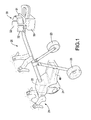
Fig. 1 is a partial perspective view of a remote-controlled electric golf bag cart in accordance with the present invention; -
Fig. 2 is a functional block diagram of the remote-controlled electric golf bag cart inFig. 1 ; -
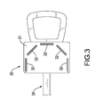
Fig. 3 is a partially enlarged top view of the remote-controlled electric golf bag cart inFig. 1 ; -
Fig. 4 is a first operation side view of the remote-controlled electric golf bag cart inFig. 1 when detecting a distance to the ground; -
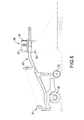
Fig. 5 is a second operation side view of the remote-controlled electric golf bag cart inFig. 1 when detecting a distance to the ground; -
Fig. 6 is a third operation side view of the remote-controlled electric golf bag cart inFig. 1 when detecting a distance to the ground; and -
Fig. 7 is an operation side view of the remote-controlled electric golf bag cart inFig. 1 when following a person with a remote control. - With reference to
Figs. 1 and2 , a remote-controlled electric golf bag cart in accordance with the present invention has aremote control 10, asupport frame 20, an antenna set 30 and acontrol module 40. - The
remote control 10 serves to transmit a distance measurement signal. In the present embodiment, theremote control 10 is built in with an acceleration command, a deceleration command, a left turn command and a right turn command. Theremote control 10 hasmultiple buttons 11 to correspond to the acceleration command, the deceleration command, the left turn command and the right turn command for users to issue a corresponding command after operating theremote control 10. - The
support frame 20 has a wheel assembly, a golf bag stand 21 and amotor assembly 22. Themotor assembly 22 is connected with the wheel assembly to drive the wheel assembly. In the present embodiment, the wheel assembly has a set offront wheels 23 and arear wheel 24. Themotor assembly 22 is connected with therear wheel 24 and has a drivingmember 221, abrake member 222 and adiverting member 223. The drivingmember 221 drives therear wheel 24 to rotate. Thebrake member 222 stops therear wheel 24 from rotating. Thediverting member 223 changes a moving direction of therear wheel 24. - The antenna set 30 is mounted on the
support frame 20 and receives a distance measurement signal transmitted from theremote control 10 and hasmultiple antenna units 32 facing to at least the front side, the left side, the right side of thesupport frame 20. Theantenna units 32 serve to receive the distance measurement signals transmitted from theremote control 10 and their detailed structure is described later. In the present embodiment, eachantenna unit 32 is a panel antenna, and the antenna set 30 further receives the acceleration command, the deceleration command, the left turn command and the right turn command transmitted from theremote control 10. - The control module is mounted on the
support frame 20, is electrically connected to the antenna set 30 and themotor assembly 22, and sets a minimum distance. After acquiring the distance measurement signal received from the antenna set 30, thecontrol module 40 determines an orientation of theremote control 10 with respect to the antenna set 30, calculates a distance between theremote control 10 and the antenna set 30, and compare the distance with the minimum distance. If the distance is greater than the minimum distance, thecontrol module 40 controls themotor assembly 22 to drive the wheel assembly so that thesupport frame 20 approaches theremote control 10 to maintain the distance between the antenna set 30 and theremote control 10 to be not less than the minimum distance. - The detailed structure of the antenna set 30 is further described as follows. The antenna set 30 has a mounting
base 31,multiple antenna units 32 and an antenna-switchingunit 33. The mountingbase 31 is securely mounted on a top of a front end of thesupport frame 20. Theantenna units 32 are securely and erectly mounted on the mountingbase 31, and respectively face to the front side, the left side, the right side, the left front side and the right front side of thesupport frame 20 as shown inFig. 3 . The antenna-switchingunit 33 is electrically connected to theantenna units 32. - The
control module 40 has anantenna control unit 41 and a body control module (BCM) 42. - The
antenna control unit 41 is electrically connected to the antenna-switchingunit 33 to acquire the distance measurement signals received from therespective antenna units 32. After detecting a field strength of the received distance measurement signal from eachantenna unit 32, theantenna control unit 41 determines an orientation of theremote control 10 with respect to the antenna set 30 according to the field strength of the received distance measurement signal of eachantenna unit 32, calculates the distance between theremote control 10 and the antenna set 30, and outputs a corresponding orientation datum and a corresponding distance datum. - The
BCM 42 is electrically connected to theantenna control unit 41 and the drivingmember 221, thebrake member 222 and the divertingmember 223 of themotor assembly 22, and is built in with the minimum distance. After receiving the orientation datum and the distance datum outputted from theantenna control unit 41, theBCM 42 determines if a distance corresponding to the distance datum is greater than the minimum distance, if positive, drives the drivingmember 221 and the divertingmember 223 of themotor assembly 22 for thesupport frame 20 to move forward toward an orientation of theremote control 10 corresponding to the orientation datum, keeps receiving the orientation datum and the distance datum, and if a distance corresponding to the received distance datum is not greater than the minimum distance, activates thebrake member 222 of themotor assembly 22 to stop thesupport frame 20 from moving forward. - The
antenna control unit 41 that determines the orientation and the distance between theremote control 10 and the antenna set 30 according to the field strength of the received distance measurement signal of eachantenna unit 32 can detect a received signal strength indicator (RSSI) value of the received distance measurement signal of eachantenna unit 32, and is built in with a back propagation network to acquire the orientation datum and the distance datum corresponding to the received RSSI values of eachantenna unit 32 inputted to the back propagation network. - The
BCM 42 is built in with multiple speed levels and drives the drivingmember 221 according to one of the speed levels. When receiving the acceleration command transmitted from theremote control 10, theBCM 42 increases the moving speed of the drivingmember 221 from the current speed level to a next higher speed level. Preferably, the speeds per hour corresponding to the speed levels may be set to 1.5 km/hour, 3 km/hour, 4.5 km/hour and the like. Similarly, when receiving the deceleration command transmitted from theremote control 10, theBCM 42 decreases the moving speed of the drivingmember 221 from the current speed level to a next lower speed level. When receiving the left turn command or the right turn command transmitted from theremote control 10, theBCM 42 drives the divertingmember 223 for thesupport frame 20 to make a left turn or a right turn. - As the ground condition of a golf field may be rough, to let the remote-controlled electric golf bag cart automatically stay away from a bumpy area on the road, the remote-controlled electric golf bag cart further has a set of
ultrasonic transceivers 50 mounted on a bottom of the front end of thesupport frame 20, transmitting ultrasonic waves to the ground and receiving reflected waves. Thecontrol module 40 further has anultrasonic control unit 43. TheBCM 42 is further built in with a maximum distance to the ground and a minimum distance to the ground. Theultrasonic control unit 43 is electrically connected to the set ofultrasonic transceivers 50 and theBCM 42, calculates a distance of the set ofultrasonic transceivers 50 above the ground after the set ofultrasonic transceivers 50 transmits an ultrasonic wave and receives a reflected wave, and outputs the distance above the ground to theBCM 42. When themotor assembly 22 drives thesupport frame 20 to move forward, theBCM 42 continuously receives the distance above the ground and compares it with the maximum distance to the ground and the minimum distance to the ground. With reference toFigs. 4 to 6 , when the distance above the ground falls between the maximum distance to the ground and the minimum distance to the ground, theBCM 42 controls themotor assembly 22 to continuously drive thesupport frame 20 to move forward and follow theremote control 10. When the distance above the ground is less than the minimum distance to the ground, it indicates a bump in the road. When the distance above the ground is more than the maximum distance to the ground, it indicates a pit in the road. Hence, when determining the distance above the ground is more than the maximum distance to the ground or less than the minimum distance to the ground, theBCM 42 stops thesupport frame 20 from moving and selectively drives the divertingmember 223 to make a turn so as to stay away from the bump or the pit. - Besides, the distance measurement signal transmitted from the
remote control 10 is a radio signal in the 2.4 GHz ISM band. - With reference to
Fig. 7 , when the remote-controlled golf bag cart is operated, theremote control 10 can be carried on a user's body. Thecontrol module 40 mounted in thesupport frame 20 determines an orientation of theremote control 10 with respect to theremote control 10 according to the distance measurement signal transmitted from theremote control 10 and calculates a distance therebetween so that the orientation and distance of the user relative to thesupport frame 20 can be obtained. Such acquisition of the distance and orientation of the remote control is not affected by other persons between theremote control 10 and thesupport frame 20. Theantenna control unit 41 in thecontrol module 40 can accurately acquire the orientation and distance of a target, that is, a user carrying theremote control 10, to be followed. After receiving the orientation datum and the distance datum, theBCM 42 then drives thesupport frame 20 to move forward toward theremote control 10 to achieve the purpose that the remote-controlled electric golf bag cart accurately follows a user. Based on the mechanism using ultrasonic waves to detect a distance to the ground, the remote-controlled electric golf bag cart can automatically stay away from a bumpy road condition to prevent itself from being stuck in a pit, blocked by stairs or damaged by road condition during the following course. - In sum, the remote-controlled electric golf bag cart can get rid of the influence of other persons or obstacles in the field, which may result in incorrect determination of the orientation and distance to the target to be followed, to accurately follow the user carrying the remote control, thereby providing a smoother operation.
- Even though numerous characteristics and advantages of the present invention have been set forth in the foregoing description, together with details of the structure and function of the invention, the disclosure is illustrative only. Changes may be made in detail, especially in matters of shape, size, and arrangement of parts within the principles of the invention to the full extent indicated by the broad general meaning of the terms in which the appended claims are expressed.
Claims (7)
- A remote-controlled electric golf bag cart comprising:a remote control (10) transmitting a distance measurement signal;a support frame (20) having a wheel assembly, a golf bag stand (21) and a motor assembly (22), wherein the motor assembly (22) is connected with the wheel assembly to drive the wheel assembly; andan antenna set (30) mounted on the support frame (20), having multiple antenna units (32) facing to at least a front side, a left side, a right side of the support frame (20), and receiving the distance measurement signal transmitted from the remote control (10) with the antenna units (32);the remote-controlled electric golf bag cart further comprising:a set of ultrasonic transceivers (50) mounted on a bottom of the front side of the support frame (20), transmitting ultrasonic waves to the ground and receiving reflected waves; anda control module (40) mounted on the support frame (20), electrically connected to the antenna set (30) and the motor assembly (22), and setting a minimum distance, determining an orientation of the remote control (10) with respect to the antenna set (30) after acquiring the distance measurement signal received from the antenna set (30), calculating a distance between the remote control (10) and the antenna set (30), and comparing the distance with the minimum distance, and if the distance is greater than the minimum distance, controlling the motor assembly (22) to drive the wheel assembly for the support frame (20) to approach the remote control (10), the control module having:an ultrasonic control unit (43) electrically connected to the set of ultrasonic transceivers (50), calculating a distance of the set of ultrasonic transceivers (50) above the ground after the set of ultrasonic transceivers (50) transmits an ultrasonic wave and receives a reflected wave, and outputting the distance above the ground; anda body control module (BCM) (42) electrically connected to the motor assembly (22) and the ultrasonic control unit (43), built in with a maximum distance to the ground and a minimum distance to the ground, continuously receiving a distance above the ground and comparing the distance above the ground with the maximum distance to the ground and the minimum distance to the ground when the motor assembly (22) drives the support frame (20) to move forward, controlling the motor assembly (22) to continuously drive the support frame (20) to move forward when the distance above ground falls between the maximum distance to the ground and the minimum distance to the ground, stopping the support frame (20) from moving and selectively driving the motor assembly (22) to make a turn when determining the distance above the ground is more than the maximum distance to the ground or less than the minimum distance to the ground.
- The remote-controlled electric golf bag cart as claimed in claim 1, wherein
the wheel assembly has a set of front wheels (23) and a rear wheel (24); and
the motor assembly (22) is connected with the rear wheel (24) and has:a driving member (221) driving the rear wheel (24) to rotate;a brake member (222) stopping the rear wheel (24) from rotating; anda diverting member (223) changing a moving direction of the rear wheel (24). - The remote-controlled electric golf bag cart as claimed in claim 1, wherein the antenna set (30) has:a mounting base (31) securely mounted on a top of a front side of the support frame (20);multiple antenna units (32) securely and erectly mounted on the mounting base (31), and respectively facing to the front side, the left side, the right side, a left front side and a right front side of the support frame (20); andan antenna-switching unit (33) electrically connected to the antenna units (32).
- The remote-controlled electric golf bag cart as claimed in claim 3, wherein
the control module (40) has an antenna control unit (41) electrically connected to the antenna-switching unit (33) to acquire the distance measurement signals received from the respective antenna units (32), determining an orientation of the remote control (10) with respect to the antenna set (30) according to a field strength of the received distance measurement signal of each antenna unit (32) after detecting the field strength of the received distance measurement signal from each antenna unit (32), calculating the distance between the remote control (10) and the antenna set (30), and outputting a corresponding orientation datum and a corresponding distance datum; and
the BCM (42) is electrically connected to the antenna control unit (41) and the driving member (221), the brake member (222) and the diverting member (223) of the motor assembly (22), and built in with the minimum distance, determining if a distance corresponding to the distance datum is greater than the minimum distance after receiving the orientation datum and the distance datum outputted from the antenna control unit (41), if positive, driving the driving member (221) and the diverting member (223) of the motor assembly (22) for the support frame (20) to move forward toward an orientation of the remote control (10) corresponding to the orientation datum, keeping receiving the orientation datum and the distance datum, and if a distance corresponding to the received distance datum is not greater than the minimum distance, activating the brake member (222) of the motor assembly (22) to stop the support frame (20) from moving forward. - The remote-controlled electric golf bag cart as claimed in any one of claims 2 to 4, wherein
the remote control (10) is built in with an acceleration command and a deceleration command and has multiple buttons (11) to correspond to the acceleration command and the deceleration command so that the remote control (10) is operated to transmit the acceleration command or the deceleration command and the antenna set (30) receives the acceleration command or the deceleration command transmitted from the remote control (10); and
the BCM (42) is built in with multiple speed levels and drives the driving member (221) according to one of the speed levels, increases a moving speed of the driving member (221) from a current speed level to a next higher speed level when receiving the acceleration command transmitted from the remote control (10), and decreases the moving speed of the driving member (221) from the current speed level to a next lower speed level when receiving the deceleration command transmitted from the remote control (10). - The remote-controlled electric golf bag cart as claimed in any one of claims 2 to 5, wherein
the remote control (10) is built in with a left turn command and a right turn command and has multiple buttons (11) to correspond to the left turn command and the right turn command so that the remote control (10) is operated to transmit the left turn command or the right turn command and the antenna set (30) receives the left turn command or the right turn command transmitted from the remote control (10); and
the BCM (42) drives the diverting member (223) to turn the support frame (20) to the left or to the right when receiving the left turn command or the right turn command transmitted from the remote control (10). - The remote-controlled electric golf bag cart as claimed in claim 5 or 6, wherein the distance measurement signal transmitted from the remote control (10) is a radio signal in the 2.4 GHz ISM band.
Priority Applications (1)
| Application Number | Priority Date | Filing Date | Title |
|---|---|---|---|
| EP12192460.9A EP2730482B1 (en) | 2012-11-13 | 2012-11-13 | Remote-controlled electric golf bag cart |
Applications Claiming Priority (1)
| Application Number | Priority Date | Filing Date | Title |
|---|---|---|---|
| EP12192460.9A EP2730482B1 (en) | 2012-11-13 | 2012-11-13 | Remote-controlled electric golf bag cart |
Publications (2)
| Publication Number | Publication Date |
|---|---|
| EP2730482A1 EP2730482A1 (en) | 2014-05-14 |
| EP2730482B1 true EP2730482B1 (en) | 2015-12-30 |
Family
ID=47177821
Family Applications (1)
| Application Number | Title | Priority Date | Filing Date |
|---|---|---|---|
| EP12192460.9A Not-in-force EP2730482B1 (en) | 2012-11-13 | 2012-11-13 | Remote-controlled electric golf bag cart |
Country Status (1)
| Country | Link |
|---|---|
| EP (1) | EP2730482B1 (en) |
Families Citing this family (1)
| Publication number | Priority date | Publication date | Assignee | Title |
|---|---|---|---|---|
| KR102450997B1 (en) * | 2020-11-27 | 2022-10-07 | 주식회사 티티엔지 | A routine-based cart system that recognizes and operates a user's specific behavior and a cart control method using the system |
Family Cites Families (6)
| Publication number | Priority date | Publication date | Assignee | Title |
|---|---|---|---|---|
| US4109186A (en) * | 1974-04-17 | 1978-08-22 | Gettig Engineering & Manufacturing Co., Inc. | Self-propelled golf cart |
| US5137103A (en) * | 1991-05-30 | 1992-08-11 | Cartmell James R | Remote controlled golf bag cart |
| GB9323316D0 (en) * | 1993-11-11 | 1994-01-05 | Crowe Gordon M | Motorized carrier |
| US5944132A (en) * | 1995-07-20 | 1999-08-31 | Golfpro International, Inc. | Method and apparatus for controlling robotic golf caddy apparatus |
| US7353089B1 (en) * | 2004-04-13 | 2008-04-01 | P.E.M. Technologies, Llc | Method and system for a signal guided motorized vehicle |
| TWM304440U (en) | 2006-06-06 | 2007-01-11 | Pop Three Dimensional Picture | Ornament having three-dimensional patterns |
-
2012
- 2012-11-13 EP EP12192460.9A patent/EP2730482B1/en not_active Not-in-force
Also Published As
| Publication number | Publication date |
|---|---|
| EP2730482A1 (en) | 2014-05-14 |
Similar Documents
| Publication | Publication Date | Title |
|---|---|---|
| US8905175B2 (en) | Remote-controlled electric golf bag cart | |
| KR102292262B1 (en) | Moving robot and contorlling method thereof | |
| EP3829833B1 (en) | Moving robot and controlling method thereof | |
| AU2007250460B2 (en) | Robotic golf caddy | |
| US11826616B2 (en) | Ball retrieval system and method | |
| EP2768704B1 (en) | Foldable cart with tracking arrangement | |
| EP3777506B1 (en) | Moving robot | |
| CN101639699B (en) | Intelligent automatic searching and tracking golf cart | |
| US11731008B2 (en) | Ball retrieval system and method | |
| EP2590041A2 (en) | Target-following vehicle | |
| CN201237738Y (en) | Golf cart with intelligent automatic searching and tracing function | |
| WO1999012793A1 (en) | Method and apparatus for controlling robotic golf caddy apparatus | |
| US6142251A (en) | System consisting of an automotive vehicle, preferably golf caddy, and a transmitter | |
| KR20170066036A (en) | Autonomous driving golf cart | |
| KR101468870B1 (en) | A golf cart control system using RF transmission rate measurement system | |
| CN103657019A (en) | Remote Control Electric Golf Bag Cart | |
| EP2730482A1 (en) | Remote-controlled electric golf bag cart | |
| JP2014108269A (en) | Remote control electric golf back cart | |
| KR102302733B1 (en) | System for automatically tracking moving target and the method thereof | |
| CN211752311U (en) | Hand-push electric golf bag trolley safe to use | |
| TW201410300A (en) | Remote control electric golf bag cart | |
| KR20230016887A (en) | System for automatically tracking moving target and the method thereof | |
| JPS6238910A (en) | Automatic tracking type caddie cart | |
| KR20040015936A (en) | Wireless-guidable Golf-cart | |
| KR200295061Y1 (en) | Wireless-guidable Golf-cart |
Legal Events
| Date | Code | Title | Description |
|---|---|---|---|
| PUAI | Public reference made under article 153(3) epc to a published international application that has entered the european phase |
Free format text: ORIGINAL CODE: 0009012 |
|
| 17P | Request for examination filed |
Effective date: 20131105 |
|
| AK | Designated contracting states |
Kind code of ref document: A1 Designated state(s): AL AT BE BG CH CY CZ DE DK EE ES FI FR GB GR HR HU IE IS IT LI LT LU LV MC MK MT NL NO PL PT RO RS SE SI SK SM TR |
|
| AX | Request for extension of the european patent |
Extension state: BA ME |
|
| RIC1 | Information provided on ipc code assigned before grant |
Ipc: B62B 3/12 20060101ALI20150515BHEP Ipc: A63B 55/00 20150101ALN20150515BHEP Ipc: B62B 5/00 20060101ALI20150515BHEP Ipc: B62D 1/28 20060101AFI20150515BHEP |
|
| GRAP | Despatch of communication of intention to grant a patent |
Free format text: ORIGINAL CODE: EPIDOSNIGR1 |
|
| INTG | Intention to grant announced |
Effective date: 20150701 |
|
| RAP1 | Party data changed (applicant data changed or rights of an application transferred) |
Owner name: TUNG THIH ELECTRONIC CO., LTD. |
|
| GRAS | Grant fee paid |
Free format text: ORIGINAL CODE: EPIDOSNIGR3 |
|
| GRAA | (expected) grant |
Free format text: ORIGINAL CODE: 0009210 |
|
| AK | Designated contracting states |
Kind code of ref document: B1 Designated state(s): AL AT BE BG CH CY CZ DE DK EE ES FI FR GB GR HR HU IE IS IT LI LT LU LV MC MK MT NL NO PL PT RO RS SE SI SK SM TR |
|
| REG | Reference to a national code |
Ref country code: GB Ref legal event code: FG4D |
|
| REG | Reference to a national code |
Ref country code: CH Ref legal event code: EP |
|
| REG | Reference to a national code |
Ref country code: AT Ref legal event code: REF Ref document number: 767313 Country of ref document: AT Kind code of ref document: T Effective date: 20160115 |
|
| REG | Reference to a national code |
Ref country code: IE Ref legal event code: FG4D |
|
| REG | Reference to a national code |
Ref country code: DE Ref legal event code: R096 Ref document number: 602012013334 Country of ref document: DE |
|
| REG | Reference to a national code |
Ref country code: LT Ref legal event code: MG4D |
|
| PG25 | Lapsed in a contracting state [announced via postgrant information from national office to epo] |
Ref country code: HR Free format text: LAPSE BECAUSE OF FAILURE TO SUBMIT A TRANSLATION OF THE DESCRIPTION OR TO PAY THE FEE WITHIN THE PRESCRIBED TIME-LIMIT Effective date: 20151230 Ref country code: LT Free format text: LAPSE BECAUSE OF FAILURE TO SUBMIT A TRANSLATION OF THE DESCRIPTION OR TO PAY THE FEE WITHIN THE PRESCRIBED TIME-LIMIT Effective date: 20151230 Ref country code: NO Free format text: LAPSE BECAUSE OF FAILURE TO SUBMIT A TRANSLATION OF THE DESCRIPTION OR TO PAY THE FEE WITHIN THE PRESCRIBED TIME-LIMIT Effective date: 20160330 |
|
| REG | Reference to a national code |
Ref country code: NL Ref legal event code: MP Effective date: 20151230 |
|
| REG | Reference to a national code |
Ref country code: AT Ref legal event code: MK05 Ref document number: 767313 Country of ref document: AT Kind code of ref document: T Effective date: 20151230 |
|
| PG25 | Lapsed in a contracting state [announced via postgrant information from national office to epo] |
Ref country code: GR Free format text: LAPSE BECAUSE OF FAILURE TO SUBMIT A TRANSLATION OF THE DESCRIPTION OR TO PAY THE FEE WITHIN THE PRESCRIBED TIME-LIMIT Effective date: 20160331 Ref country code: SE Free format text: LAPSE BECAUSE OF FAILURE TO SUBMIT A TRANSLATION OF THE DESCRIPTION OR TO PAY THE FEE WITHIN THE PRESCRIBED TIME-LIMIT Effective date: 20151230 Ref country code: RS Free format text: LAPSE BECAUSE OF FAILURE TO SUBMIT A TRANSLATION OF THE DESCRIPTION OR TO PAY THE FEE WITHIN THE PRESCRIBED TIME-LIMIT Effective date: 20151230 Ref country code: LV Free format text: LAPSE BECAUSE OF FAILURE TO SUBMIT A TRANSLATION OF THE DESCRIPTION OR TO PAY THE FEE WITHIN THE PRESCRIBED TIME-LIMIT Effective date: 20151230 Ref country code: FI Free format text: LAPSE BECAUSE OF FAILURE TO SUBMIT A TRANSLATION OF THE DESCRIPTION OR TO PAY THE FEE WITHIN THE PRESCRIBED TIME-LIMIT Effective date: 20151230 |
|
| PG25 | Lapsed in a contracting state [announced via postgrant information from national office to epo] |
Ref country code: NL Free format text: LAPSE BECAUSE OF FAILURE TO SUBMIT A TRANSLATION OF THE DESCRIPTION OR TO PAY THE FEE WITHIN THE PRESCRIBED TIME-LIMIT Effective date: 20151230 |
|
| PG25 | Lapsed in a contracting state [announced via postgrant information from national office to epo] |
Ref country code: IT Free format text: LAPSE BECAUSE OF FAILURE TO SUBMIT A TRANSLATION OF THE DESCRIPTION OR TO PAY THE FEE WITHIN THE PRESCRIBED TIME-LIMIT Effective date: 20151230 Ref country code: ES Free format text: LAPSE BECAUSE OF FAILURE TO SUBMIT A TRANSLATION OF THE DESCRIPTION OR TO PAY THE FEE WITHIN THE PRESCRIBED TIME-LIMIT Effective date: 20151230 Ref country code: CZ Free format text: LAPSE BECAUSE OF FAILURE TO SUBMIT A TRANSLATION OF THE DESCRIPTION OR TO PAY THE FEE WITHIN THE PRESCRIBED TIME-LIMIT Effective date: 20151230 |
|
| PG25 | Lapsed in a contracting state [announced via postgrant information from national office to epo] |
Ref country code: SM Free format text: LAPSE BECAUSE OF FAILURE TO SUBMIT A TRANSLATION OF THE DESCRIPTION OR TO PAY THE FEE WITHIN THE PRESCRIBED TIME-LIMIT Effective date: 20151230 Ref country code: AT Free format text: LAPSE BECAUSE OF FAILURE TO SUBMIT A TRANSLATION OF THE DESCRIPTION OR TO PAY THE FEE WITHIN THE PRESCRIBED TIME-LIMIT Effective date: 20151230 Ref country code: EE Free format text: LAPSE BECAUSE OF FAILURE TO SUBMIT A TRANSLATION OF THE DESCRIPTION OR TO PAY THE FEE WITHIN THE PRESCRIBED TIME-LIMIT Effective date: 20151230 Ref country code: PL Free format text: LAPSE BECAUSE OF FAILURE TO SUBMIT A TRANSLATION OF THE DESCRIPTION OR TO PAY THE FEE WITHIN THE PRESCRIBED TIME-LIMIT Effective date: 20151230 Ref country code: SK Free format text: LAPSE BECAUSE OF FAILURE TO SUBMIT A TRANSLATION OF THE DESCRIPTION OR TO PAY THE FEE WITHIN THE PRESCRIBED TIME-LIMIT Effective date: 20151230 Ref country code: IS Free format text: LAPSE BECAUSE OF FAILURE TO SUBMIT A TRANSLATION OF THE DESCRIPTION OR TO PAY THE FEE WITHIN THE PRESCRIBED TIME-LIMIT Effective date: 20160430 Ref country code: RO Free format text: LAPSE BECAUSE OF FAILURE TO SUBMIT A TRANSLATION OF THE DESCRIPTION OR TO PAY THE FEE WITHIN THE PRESCRIBED TIME-LIMIT Effective date: 20151230 |
|
| REG | Reference to a national code |
Ref country code: DE Ref legal event code: R097 Ref document number: 602012013334 Country of ref document: DE |
|
| PG25 | Lapsed in a contracting state [announced via postgrant information from national office to epo] |
Ref country code: DK Free format text: LAPSE BECAUSE OF FAILURE TO SUBMIT A TRANSLATION OF THE DESCRIPTION OR TO PAY THE FEE WITHIN THE PRESCRIBED TIME-LIMIT Effective date: 20151230 |
|
| PLBE | No opposition filed within time limit |
Free format text: ORIGINAL CODE: 0009261 |
|
| STAA | Information on the status of an ep patent application or granted ep patent |
Free format text: STATUS: NO OPPOSITION FILED WITHIN TIME LIMIT |
|
| 26N | No opposition filed |
Effective date: 20161003 |
|
| REG | Reference to a national code |
Ref country code: FR Ref legal event code: PLFP Year of fee payment: 5 |
|
| PG25 | Lapsed in a contracting state [announced via postgrant information from national office to epo] |
Ref country code: BE Free format text: LAPSE BECAUSE OF FAILURE TO SUBMIT A TRANSLATION OF THE DESCRIPTION OR TO PAY THE FEE WITHIN THE PRESCRIBED TIME-LIMIT Effective date: 20151230 |
|
| PG25 | Lapsed in a contracting state [announced via postgrant information from national office to epo] |
Ref country code: SI Free format text: LAPSE BECAUSE OF FAILURE TO SUBMIT A TRANSLATION OF THE DESCRIPTION OR TO PAY THE FEE WITHIN THE PRESCRIBED TIME-LIMIT Effective date: 20151230 |
|
| REG | Reference to a national code |
Ref country code: CH Ref legal event code: PL |
|
| PG25 | Lapsed in a contracting state [announced via postgrant information from national office to epo] |
Ref country code: LI Free format text: LAPSE BECAUSE OF NON-PAYMENT OF DUE FEES Effective date: 20161130 Ref country code: CH Free format text: LAPSE BECAUSE OF NON-PAYMENT OF DUE FEES Effective date: 20161130 |
|
| REG | Reference to a national code |
Ref country code: IE Ref legal event code: MM4A |
|
| REG | Reference to a national code |
Ref country code: FR Ref legal event code: PLFP Year of fee payment: 6 |
|
| PG25 | Lapsed in a contracting state [announced via postgrant information from national office to epo] |
Ref country code: LU Free format text: LAPSE BECAUSE OF NON-PAYMENT OF DUE FEES Effective date: 20161130 |
|
| PGFP | Annual fee paid to national office [announced via postgrant information from national office to epo] |
Ref country code: FR Payment date: 20170921 Year of fee payment: 6 Ref country code: GB Payment date: 20170921 Year of fee payment: 6 |
|
| PG25 | Lapsed in a contracting state [announced via postgrant information from national office to epo] |
Ref country code: IE Free format text: LAPSE BECAUSE OF NON-PAYMENT OF DUE FEES Effective date: 20161113 |
|
| PGFP | Annual fee paid to national office [announced via postgrant information from national office to epo] |
Ref country code: DE Payment date: 20170927 Year of fee payment: 6 |
|
| PG25 | Lapsed in a contracting state [announced via postgrant information from national office to epo] |
Ref country code: CY Free format text: LAPSE BECAUSE OF FAILURE TO SUBMIT A TRANSLATION OF THE DESCRIPTION OR TO PAY THE FEE WITHIN THE PRESCRIBED TIME-LIMIT Effective date: 20151230 Ref country code: HU Free format text: LAPSE BECAUSE OF FAILURE TO SUBMIT A TRANSLATION OF THE DESCRIPTION OR TO PAY THE FEE WITHIN THE PRESCRIBED TIME-LIMIT; INVALID AB INITIO Effective date: 20121113 |
|
| PG25 | Lapsed in a contracting state [announced via postgrant information from national office to epo] |
Ref country code: PT Free format text: LAPSE BECAUSE OF FAILURE TO SUBMIT A TRANSLATION OF THE DESCRIPTION OR TO PAY THE FEE WITHIN THE PRESCRIBED TIME-LIMIT Effective date: 20151230 Ref country code: MC Free format text: LAPSE BECAUSE OF FAILURE TO SUBMIT A TRANSLATION OF THE DESCRIPTION OR TO PAY THE FEE WITHIN THE PRESCRIBED TIME-LIMIT Effective date: 20151230 Ref country code: MK Free format text: LAPSE BECAUSE OF FAILURE TO SUBMIT A TRANSLATION OF THE DESCRIPTION OR TO PAY THE FEE WITHIN THE PRESCRIBED TIME-LIMIT Effective date: 20151230 |
|
| PG25 | Lapsed in a contracting state [announced via postgrant information from national office to epo] |
Ref country code: BG Free format text: LAPSE BECAUSE OF FAILURE TO SUBMIT A TRANSLATION OF THE DESCRIPTION OR TO PAY THE FEE WITHIN THE PRESCRIBED TIME-LIMIT Effective date: 20151230 |
|
| PG25 | Lapsed in a contracting state [announced via postgrant information from national office to epo] |
Ref country code: MT Free format text: LAPSE BECAUSE OF NON-PAYMENT OF DUE FEES Effective date: 20161113 |
|
| PG25 | Lapsed in a contracting state [announced via postgrant information from national office to epo] |
Ref country code: AL Free format text: LAPSE BECAUSE OF FAILURE TO SUBMIT A TRANSLATION OF THE DESCRIPTION OR TO PAY THE FEE WITHIN THE PRESCRIBED TIME-LIMIT Effective date: 20151230 Ref country code: TR Free format text: LAPSE BECAUSE OF FAILURE TO SUBMIT A TRANSLATION OF THE DESCRIPTION OR TO PAY THE FEE WITHIN THE PRESCRIBED TIME-LIMIT Effective date: 20151230 |
|
| REG | Reference to a national code |
Ref country code: DE Ref legal event code: R119 Ref document number: 602012013334 Country of ref document: DE |
|
| GBPC | Gb: european patent ceased through non-payment of renewal fee |
Effective date: 20181113 |
|
| PG25 | Lapsed in a contracting state [announced via postgrant information from national office to epo] |
Ref country code: DE Free format text: LAPSE BECAUSE OF NON-PAYMENT OF DUE FEES Effective date: 20190601 Ref country code: FR Free format text: LAPSE BECAUSE OF NON-PAYMENT OF DUE FEES Effective date: 20181130 |
|
| PG25 | Lapsed in a contracting state [announced via postgrant information from national office to epo] |
Ref country code: GB Free format text: LAPSE BECAUSE OF NON-PAYMENT OF DUE FEES Effective date: 20181113 |