EP2730411A1 - A lead edge mechanical binding device and method - Google Patents
A lead edge mechanical binding device and method Download PDFInfo
- Publication number
- EP2730411A1 EP2730411A1 EP13188130.2A EP13188130A EP2730411A1 EP 2730411 A1 EP2730411 A1 EP 2730411A1 EP 13188130 A EP13188130 A EP 13188130A EP 2730411 A1 EP2730411 A1 EP 2730411A1
- Authority
- EP
- European Patent Office
- Prior art keywords
- knife
- binding
- cutting
- cutting cylinder
- cylinder
- Prior art date
- Legal status (The legal status is an assumption and is not a legal conclusion. Google has not performed a legal analysis and makes no representation as to the accuracy of the status listed.)
- Withdrawn
Links
- 239000000758 substrate Substances 0.000 claims abstract description 23
- 229920001971 elastomer Polymers 0.000 claims abstract description 11
- 239000005060 rubber Substances 0.000 claims abstract description 11
- 238000011144 upstream manufacturing Methods 0.000 claims description 4
- 230000000712 assembly Effects 0.000 description 5
- 238000000429 assembly Methods 0.000 description 5
- 230000003068 static effect Effects 0.000 description 4
- 229910000831 Steel Inorganic materials 0.000 description 1
- 230000007547 defect Effects 0.000 description 1
- 230000000694 effects Effects 0.000 description 1
- 238000012986 modification Methods 0.000 description 1
- 230000004048 modification Effects 0.000 description 1
- 239000010959 steel Substances 0.000 description 1
Images


Classifications
-
- B—PERFORMING OPERATIONS; TRANSPORTING
- B26—HAND CUTTING TOOLS; CUTTING; SEVERING
- B26D—CUTTING; DETAILS COMMON TO MACHINES FOR PERFORATING, PUNCHING, CUTTING-OUT, STAMPING-OUT OR SEVERING
- B26D1/00—Cutting through work characterised by the nature or movement of the cutting member or particular materials not otherwise provided for; Apparatus or machines therefor; Cutting members therefor
- B26D1/01—Cutting through work characterised by the nature or movement of the cutting member or particular materials not otherwise provided for; Apparatus or machines therefor; Cutting members therefor involving a cutting member which does not travel with the work
- B26D1/12—Cutting through work characterised by the nature or movement of the cutting member or particular materials not otherwise provided for; Apparatus or machines therefor; Cutting members therefor involving a cutting member which does not travel with the work having a cutting member moving about an axis
- B26D1/25—Cutting through work characterised by the nature or movement of the cutting member or particular materials not otherwise provided for; Apparatus or machines therefor; Cutting members therefor involving a cutting member which does not travel with the work having a cutting member moving about an axis with a non-circular cutting member
- B26D1/34—Cutting through work characterised by the nature or movement of the cutting member or particular materials not otherwise provided for; Apparatus or machines therefor; Cutting members therefor involving a cutting member which does not travel with the work having a cutting member moving about an axis with a non-circular cutting member moving about an axis parallel to the line of cut
- B26D1/40—Cutting through work characterised by the nature or movement of the cutting member or particular materials not otherwise provided for; Apparatus or machines therefor; Cutting members therefor involving a cutting member which does not travel with the work having a cutting member moving about an axis with a non-circular cutting member moving about an axis parallel to the line of cut and coacting with a rotary member
- B26D1/405—Cutting through work characterised by the nature or movement of the cutting member or particular materials not otherwise provided for; Apparatus or machines therefor; Cutting members therefor involving a cutting member which does not travel with the work having a cutting member moving about an axis with a non-circular cutting member moving about an axis parallel to the line of cut and coacting with a rotary member for thin material, e.g. for sheets, strips or the like
-
- B—PERFORMING OPERATIONS; TRANSPORTING
- B41—PRINTING; LINING MACHINES; TYPEWRITERS; STAMPS
- B41F—PRINTING MACHINES OR PRESSES
- B41F13/00—Common details of rotary presses or machines
- B41F13/54—Auxiliary folding, cutting, collecting or depositing of sheets or webs
- B41F13/56—Folding or cutting
- B41F13/60—Folding or cutting crosswise
-
- B—PERFORMING OPERATIONS; TRANSPORTING
- B65—CONVEYING; PACKING; STORING; HANDLING THIN OR FILAMENTARY MATERIAL
- B65H—HANDLING THIN OR FILAMENTARY MATERIAL, e.g. SHEETS, WEBS, CABLES
- B65H35/00—Delivering articles from cutting or line-perforating machines; Article or web delivery apparatus incorporating cutting or line-perforating devices, e.g. adhesive tape dispensers
- B65H35/04—Delivering articles from cutting or line-perforating machines; Article or web delivery apparatus incorporating cutting or line-perforating devices, e.g. adhesive tape dispensers from or with transverse cutters or perforators
- B65H35/08—Delivering articles from cutting or line-perforating machines; Article or web delivery apparatus incorporating cutting or line-perforating devices, e.g. adhesive tape dispensers from or with transverse cutters or perforators from or with revolving, e.g. cylinder, cutters or perforators
-
- B—PERFORMING OPERATIONS; TRANSPORTING
- B65—CONVEYING; PACKING; STORING; HANDLING THIN OR FILAMENTARY MATERIAL
- B65H—HANDLING THIN OR FILAMENTARY MATERIAL, e.g. SHEETS, WEBS, CABLES
- B65H45/00—Folding thin material
- B65H45/12—Folding articles or webs with application of pressure to define or form crease lines
- B65H45/28—Folding in combination with cutting
-
- Y—GENERAL TAGGING OF NEW TECHNOLOGICAL DEVELOPMENTS; GENERAL TAGGING OF CROSS-SECTIONAL TECHNOLOGIES SPANNING OVER SEVERAL SECTIONS OF THE IPC; TECHNICAL SUBJECTS COVERED BY FORMER USPC CROSS-REFERENCE ART COLLECTIONS [XRACs] AND DIGESTS
- Y10—TECHNICAL SUBJECTS COVERED BY FORMER USPC
- Y10T—TECHNICAL SUBJECTS COVERED BY FORMER US CLASSIFICATION
- Y10T83/00—Cutting
- Y10T83/465—Cutting motion of tool has component in direction of moving work
- Y10T83/4766—Orbital motion of cutting blade
- Y10T83/4795—Rotary tool
-
- Y—GENERAL TAGGING OF NEW TECHNOLOGICAL DEVELOPMENTS; GENERAL TAGGING OF CROSS-SECTIONAL TECHNOLOGIES SPANNING OVER SEVERAL SECTIONS OF THE IPC; TECHNICAL SUBJECTS COVERED BY FORMER USPC CROSS-REFERENCE ART COLLECTIONS [XRACs] AND DIGESTS
- Y10—TECHNICAL SUBJECTS COVERED BY FORMER USPC
- Y10T—TECHNICAL SUBJECTS COVERED BY FORMER US CLASSIFICATION
- Y10T83/00—Cutting
- Y10T83/465—Cutting motion of tool has component in direction of moving work
- Y10T83/4766—Orbital motion of cutting blade
- Y10T83/4795—Rotary tool
- Y10T83/483—With cooperating rotary cutter or backup
- Y10T83/4838—With anvil backup
- Y10T83/4841—With resilient anvil surface
Definitions
- the present invention relates generally to printing press and more particularly to cutting cylinders and binding devices.
- the present invention provides a binding device that applies localized pressure to a page of a printed product.
- a cutting cylinder pair for cutting a substrate in a folder of a printing press.
- the cylinder pair includes a cutting cylinder and an anvil cylinder.
- the cutting cylinder includes a knife and a binding pin adj acent the knife in a circumferential direction of the cutting cylinder.
- the anvil cylinder includes a cutting rubber, the cutting rubber engaging the knife and the binding pin as the cutting cylinder and anvil cylinder rotate.
- the binding pin is positioned on the cutting cylinder to impart a dimple to a substrate passing between the cutting cylinder and anvil cylinder.
- the cutting cylinder has a circumferential outer surface, and the knife may extend axially along the circumferential outer surface.
- One or more additional binding pins may be provided adjacent the knife in the circumferential direction, the one or more additional binding pins extending axially along the circumferential outer surface.
- a height of the binding pin may be less than a height of the knife.
- a knife box may be removably secured to the cutting cylinder, the cutting cylinder may have an axially extending recess in a circumferential outer surface of the cutting cylinder.
- the knife box may be removably secured in the recess.
- the knife box includes the knife and the binding pin.
- the knife and/or at least one binding pin may be retractable; the binding pin(s) may be positioned at a height that applies a localized pressure to a lead edge of the substrate; the binding pin(s) may be positioned at a height that dimples the substrate; and/or the binding pin(s) may be positioned to apply a localized pressure to an open edge of the substrate.
- a cutting cylinder for cutting a substrate in a folder of a printing press.
- the cutting cylinder includes: a knife box assembly including a knife or cutting blade and at least one binding device installed in the knife box assembly.
- the binding device is positioned in the knife box assembly to apply pressure to the substrate as the substrate is cut by the knife.
- the binding device includes one or more binding pins. If multiple binding pins are employed, the binding pins may be installed along a length of the knife blade.
- the knife and/or at least one binding pin may be retractable.
- the binding pin(s) may be positioned at a height that applies a localized pressure to a lead edge of the substrate, the binding pin(s) may be positioned at a height that dimples the substrate, and or the binding pin(s) may be positioned to apply a localized pressure to an open edge of the substrate.
- a folder for a printing press comprising a cutting cylinder pair according to the first embodiment, a former upstream of the cutting cylinder pair, and a pair of nip rolls located between the former and the cutting cylinder pair.
- a printing press for printing on a substrate comprising a folder according to the third embodiment and a plurality of printing units upstream of the folder.
- Fig. 1 shows a printing press including a binding device according to the present invention
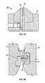
- Fig. 2(a) shows a cross sectional view of a knife box assembly of a cutting cylinder in accordance with an embodiment of the present invention
- Figure 2(b) illustrates a binding pin positioned at an angle which is different than the angle of the knife blade in accordance with an embodiment of the present invention
- Fig. 3 shows a view of a knife box assembly including two binding pins in accordance with an embodiment of the present invention
- Fig. 4(a) shows a side view of a pair of cutting cylinders with an anvil, knife box, and binding pins in accordance with an embodiment of the present invention
- Figure 4(b) shows a perspective view of a cutting cylinder with a knife box assembly installed with binding pins in accordance with an embodiment of the present invention
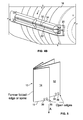
- Fig. 5 shows a product formed in accordance with an embodiment of the present invention.
- Static tackers need to be fine-tuned to a setting that is high enough to hold the lead edge of the product together but low enough to keep the delivery shingle clean.
- the former has been shifted to different positions in an attempt to find a new alignment that produces a better corrugation on the full and half page sheets.
- the present invention provides a binding device that eliminates the need to increase the static tacker strength and could potentially eliminate the need for a static tacker completely.
- Fig. 1 shows a printing press 100 including a printing section 102 and a folder section 120 for printing, cutting and folding printed products, such as newspapers, for example.
- the printing press 100 may be a perfecting, web offset, four color printing press.
- Printing press 100 may include four printing units 104 each printing on a web 2 with a different color ink, for example, cyan, magenta, yellow and black.
- Web 2 travels through press 100 in a direction A from printing section 102 to folder section 120.
- Each printing unit 104 may include two printing cylinders 130, 132 and two blanket cylinders 134, 136.
- Each printing cylinder 130, 132 carries a printing plate 131, 133 mounted thereon.
- the printing cylinders 130, 132 may be etched or imaged directly with a printing image.
- Each blanket cylinder 134, 136 includes a printing blanket 135, 137 mounted thereon.
- the printing blankets 135, 137 may be flat blankets mounted into a lockup mechanism or printing blankets 135, 137 may be tubular, gapless, sleeve-shaped blankets.
- the printing plates 131, 313 transfer images to printing blankets 135, 137 which transfer images to web 2.
- Folder section 120 includes a triangular shaped former 40 for folding web 2.
- Web 2 may also be combined with other web ribbons for simultaneous folding. Additional ribbons may be printed by another printing section or by another printing press, for example web 4.
- web 4 is a half sheet size web and thus is narrower than than full sheet size web 2.
- Web 4 is combined with web 2 so web 4 is centered and overlaid on top of web 2.
- Former 40 folds web 2 and web 4 together and in half as webs 2, 4 run down a surface of former 40.
- Webs 2, 4 are folded in half longitudinally, in the direction of travel A. Webs 2, 4 may pass through a pair of nip rolls 42.
- a printed product or book 10 is made from the two webs, full size web 2 which forms inner signature 12 and half sheet size web 4 which forms outer signature 14.
- Cutting cylinder pair 50 includes an anvil cylinder 18 and knife cylinder 16.
- knife cylinder 16 is a two around knife cylinder and includes two knife box assemblies 20.
- Anvil cylinder 18 is a two around anvil cylinder and includes two cutting rubber assemblies 24.
- Each knife box assembly 20 includes a binding device 30 in accordance with a preferred embodiment of the present invention as well as a knife 22. Any number of knife boxes 20/cutting rubber assemblies 24 may be provided as desired on cylinders 16/18.
- Figs. 2 to 4 show binding device 30 in accordance with the present invention.
- Binding device 30 is installed along a length of knife 22 on the lead edge side (with respect to the direction of travel A), inside knife box assembly 20.
- a binding pin 32 of binding device 30 dimples a lead edge 11 ( Figs 1 , 5 ) of webs 2, 4 against a cutting rubber 24.
- the localized pressure dimples 36 and binds pages of newly cut product 10 together, holding a lead edge 11 of product 10 closed as product 10 travels through folder 120, thereby reducing dog earring and other printing defects.
- Product 10 includes a signature 14 cut from web 4 and a signature 12 cut from web 2.
- Multiple binding pins 32 may be located along knife 22 for dimpling across a product 10 to bind any size product, including half page sized signatures 14.
- Fig. 2(a) shows a cross sectional view of a knife box assembly 20 of cutting cylinder 16.
- Binding device 30 includes binding pin 32 that is installed in the knife box assembly 20 adjacent to knife 22. Multiple binding pins may be provided. Binding pin 32 may be mechanically set at a desired height. The height of binding pin 32 is adjustable and may be equal to, greater than or less than a height of knife blade 22. The angle of the binding pin can be the same or different than the knife blade angle.
- Figure 2(b) illustrates a binding pin 32 positioned at an angle which is different than the angle of the knife blade 22.
- binding pin 32 is set to a height less than a height of knife blade 22.
- the thickness of the printed product or book being cut is considered when determining the set height for binding pin 32.
- the height of each binding pin may be set individually. For example, when viewing Fig. 5 , a binding pin dimpling signatures 14 and 12 together may be set to a lower height than a binding pin setup to dimple only signature 12.
- binding pin 32 is instead set to a height greater than the knife 22, a recess may be provided in the cutting rubber so that the presence of the binding pin does not interfere with the cutting action of the knife 22.
- binding pins 32 apply dimpling to signatures 12, 14 without causing commercially unacceptable damage to signatures 12, 14.
- Binding pins 32 may be made out of, for example, steel.
- Fig. 3 shows a view of knife box assembly 20 including two binding pins 32, 34 in accordance with a further preferred embodiment of the present invention. Additional pins and/or additional pin positions may be installed along a length of knife blade 22 to achieve the desired binding effect. Binding pins 32, 34 may be arranged to bind open edges of a half page product (signature 14), full page product (signature 12) and any combination thereof. Binding pins and knife blades may be fixed. Binding pins and knife blades may also be adjustably set at a plurality heights as desired. Binding pins and/or knife blades may also be retractable and/or controlled via a cam mechanism.
- Fig. 4(a) shows a side view of a pair of cutting cylinders.
- Cutting cylinder 16 includes two knife box assemblies 20 having two binding devices 30 with binding pins 32 installed. Each knife box assembly 20 includes a binding device 30 and associated binding pins 32.
- Anvil cylinder 18 includes two cutting rubbers 24 which are used to counteract knife blades 22 and binding pins 32.
- Cutting cylinder 16 may be retrofitted with a knife box assembly 20 which includes binding pins 32 to replace previous knife box assemblies.
- Figure 4(b) shows a perspective view of a cutting cylinder 16 with a knife box assembly 20 installed with knife blade 22 and binding pins 32, 34.
- Fig. 5 shows a half page size signature 14 wrapped folded around a full page size signature 12 to form a book or printed product 10. Open edges are indicated as is the "spine" or former folded edge of the product 10 and the lead edge 11 of product 10 is shown. The spine of the product is formed by the longitudinal fold imparted by former 40. Dimples 36 made on signatures 12, 14 in accordance with the present invention are shown. Binding pins 32, 34 may impart dimples on any number of pages as desired.
Landscapes
- Engineering & Computer Science (AREA)
- Mechanical Engineering (AREA)
- Life Sciences & Earth Sciences (AREA)
- Forests & Forestry (AREA)
- Folding Of Thin Sheet-Like Materials, Special Discharging Devices, And Others (AREA)
- Nonmetal Cutting Devices (AREA)
Abstract
A cutting cylinder pair for cutting a substrate in a folder of a printing press is provided which includes a cutting cylinder, the cutting cylinder including a knife and a binding pin adjacent the knife in a circumferential direction of the cutting cylinder; and an anvil cylinder, the anvil cylinder including a cutting rubber, the cutting rubber engaging the knife and the binding pin as the cutting cylinder and anvil cylinder rotate, the binding pin positioned on the cutting cylinder to impart a dimple to a substrate passing between the cutting cylinder and anvil cylinder.
Description
- This application claims priority to United States Provisional Application Serial Number
61/712,119 filed October 10, 2012 - The present invention relates generally to printing press and more particularly to cutting cylinders and binding devices.
- As known in the art, static tackers help hold printed products closed. However, as tacker levels are increased, the delivery shingle quality deteriorates. Corrugating products helps stiffen the product but causes the lead edge to open and dog ear when the open edge aligns with a peak of a corrugation. Products configured with an exterior half page have two open edges which makes alignment with corrugation even more difficult to achieve.
- The present invention provides a binding device that applies localized pressure to a page of a printed product.
- In accordance with a first embodiment of the present invention, a cutting cylinder pair for cutting a substrate in a folder of a printing press is provided. The cylinder pair includes a cutting cylinder and an anvil cylinder. The cutting cylinder includes a knife and a binding pin adj acent the knife in a circumferential direction of the cutting cylinder. The anvil cylinder includes a cutting rubber, the cutting rubber engaging the knife and the binding pin as the cutting cylinder and anvil cylinder rotate. The binding pin is positioned on the cutting cylinder to impart a dimple to a substrate passing between the cutting cylinder and anvil cylinder.
- In accordance with another aspect of the first embodiment, the cutting cylinder has a circumferential outer surface, and the knife may extend axially along the circumferential outer surface. One or more additional binding pins may be provided adjacent the knife in the circumferential direction, the one or more additional binding pins extending axially along the circumferential outer surface.
- In accordance with another aspect of the first embodiment, a height of the binding pin may be less than a height of the knife.
- In accordance with another aspect of the first embodiment, a knife box may be removably secured to the cutting cylinder, the cutting cylinder may have an axially extending recess in a circumferential outer surface of the cutting cylinder. The knife box may be removably secured in the recess. The knife box includes the knife and the binding pin.
- In accordance with other aspects of the first embodiment: the knife and/or at least one binding pin may be retractable; the binding pin(s) may be positioned at a height that applies a localized pressure to a lead edge of the substrate; the binding pin(s) may be positioned at a height that dimples the substrate; and/or the binding pin(s) may be positioned to apply a localized pressure to an open edge of the substrate.
- In accordance with a second embodiment of the present invention, a cutting cylinder for cutting a substrate in a folder of a printing press is provided. The cutting cylinder includes: a knife box assembly including a knife or cutting blade and at least one binding device installed in the knife box assembly. The binding device is positioned in the knife box assembly to apply pressure to the substrate as the substrate is cut by the knife.
- In accordance with another aspect of the second embodiment, the binding device includes one or more binding pins. If multiple binding pins are employed, the binding pins may be installed along a length of the knife blade.
- In accordance with another aspect of the second embodiment, wherein the knife and/or at least one binding pin may be retractable.
- In accordance with another aspect of the second embodiment, the binding pin(s) may be positioned at a height that applies a localized pressure to a lead edge of the substrate, the binding pin(s) may be positioned at a height that dimples the substrate, and or the binding pin(s) may be positioned to apply a localized pressure to an open edge of the substrate.
- In accordance with a third embodiment of the present invention, a folder for a printing press comprising a cutting cylinder pair according to the first embodiment, a former upstream of the cutting cylinder pair, and a pair of nip rolls located between the former and the cutting cylinder pair.
- In accordance with a fourth embodiment of the present invention, a printing press for printing on a substrate comprising a folder according to the third embodiment and a plurality of printing units upstream of the folder.
- A preferred embodiment of the present invention will be elucidated with reference to the drawings, in which:
-
Fig. 1 shows a printing press including a binding device according to the present invention; -
Fig. 2(a) shows a cross sectional view of a knife box assembly of a cutting cylinder in accordance with an embodiment of the present invention; -
Figure 2(b) illustrates a binding pin positioned at an angle which is different than the angle of the knife blade in accordance with an embodiment of the present invention; -
Fig. 3 shows a view of a knife box assembly including two binding pins in accordance with an embodiment of the present invention; -
Fig. 4(a) shows a side view of a pair of cutting cylinders with an anvil, knife box, and binding pins in accordance with an embodiment of the present invention; -
Figure 4(b) shows a perspective view of a cutting cylinder with a knife box assembly installed with binding pins in accordance with an embodiment of the present invention; and -
Fig. 5 shows a product formed in accordance with an embodiment of the present invention. - Static tackers need to be fine-tuned to a setting that is high enough to hold the lead edge of the product together but low enough to keep the delivery shingle clean. The former has been shifted to different positions in an attempt to find a new alignment that produces a better corrugation on the full and half page sheets.
- The present invention provides a binding device that eliminates the need to increase the static tacker strength and could potentially eliminate the need for a static tacker completely.
-
Fig. 1 shows aprinting press 100 including aprinting section 102 and afolder section 120 for printing, cutting and folding printed products, such as newspapers, for example. Theprinting press 100 may be a perfecting, web offset, four color printing press.Printing press 100 may include fourprinting units 104 each printing on aweb 2 with a different color ink, for example, cyan, magenta, yellow and black.Web 2 travels throughpress 100 in a direction A fromprinting section 102 tofolder section 120. Eachprinting unit 104 may include twoprinting cylinders blanket cylinders printing cylinder printing plate printing cylinders blanket cylinder printing blanket printing blankets printing blankets printing plates 131, 313 transfer images to printingblankets web 2. - From the
printing section 102,web 2 then entersfolder section 120.Folder section 120 includes a triangular shaped former 40 for foldingweb 2.Web 2 may also be combined with other web ribbons for simultaneous folding. Additional ribbons may be printed by another printing section or by another printing press, forexample web 4. In this embodiment,web 4 is a half sheet size web and thus is narrower than than fullsheet size web 2.Web 4 is combined withweb 2 soweb 4 is centered and overlaid on top ofweb 2. Former 40folds web 2 andweb 4 together and in half aswebs Webs travel A. Webs nip rolls 42. As shown inFig. 5 , a printed product orbook 10 is made from the two webs,full size web 2 which formsinner signature 12 and halfsheet size web 4 which formsouter signature 14. -
Webs cutting cylinder pair 50.Cutting cylinder pair 50 includes ananvil cylinder 18 andknife cylinder 16. In the embodiment shown,knife cylinder 16 is a two around knife cylinder and includes twoknife box assemblies 20.Anvil cylinder 18 is a two around anvil cylinder and includes two cuttingrubber assemblies 24. Eachknife box assembly 20 includes abinding device 30 in accordance with a preferred embodiment of the present invention as well as aknife 22. Any number ofknife boxes 20/cuttingrubber assemblies 24 may be provided as desired oncylinders 16/18. -
Figs. 2 to 4 show binding device 30 in accordance with the present invention. Bindingdevice 30 is installed along a length ofknife 22 on the lead edge side (with respect to the direction of travel A), insideknife box assembly 20. As cuttingcylinder 16 rotates andwebs pin 32 of bindingdevice 30 dimples a lead edge 11 (Figs 1 ,5 ) ofwebs rubber 24. The localized pressure dimples 36 and binds pages of newly cutproduct 10 together, holding alead edge 11 ofproduct 10 closed asproduct 10 travels throughfolder 120, thereby reducing dog earring and other printing defects.Product 10 includes asignature 14 cut fromweb 4 and asignature 12 cut fromweb 2. Multiplebinding pins 32 may be located alongknife 22 for dimpling across aproduct 10 to bind any size product, including half pagesized signatures 14. -
Fig. 2(a) shows a cross sectional view of aknife box assembly 20 of cuttingcylinder 16. Bindingdevice 30 includes bindingpin 32 that is installed in theknife box assembly 20 adjacent toknife 22. Multiple binding pins may be provided. Bindingpin 32 may be mechanically set at a desired height. The height of bindingpin 32 is adjustable and may be equal to, greater than or less than a height ofknife blade 22. The angle of the binding pin can be the same or different than the knife blade angle.Figure 2(b) illustrates abinding pin 32 positioned at an angle which is different than the angle of theknife blade 22. - In a preferred embodiment, binding
pin 32 is set to a height less than a height ofknife blade 22. The thickness of the printed product or book being cut is considered when determining the set height for bindingpin 32. The height of each binding pin may be set individually. For example, when viewingFig. 5 , a bindingpin dimpling signatures only signature 12. - If the binding
pin 32 is instead set to a height greater than theknife 22, a recess may be provided in the cutting rubber so that the presence of the binding pin does not interfere with the cutting action of theknife 22. - In accordance with a preferred embodiment of the present invention, binding
pins 32 apply dimpling tosignatures signatures -
Fig. 3 shows a view ofknife box assembly 20 including twobinding pins knife blade 22 to achieve the desired binding effect. Binding pins 32, 34 may be arranged to bind open edges of a half page product (signature 14), full page product (signature 12) and any combination thereof. Binding pins and knife blades may be fixed. Binding pins and knife blades may also be adjustably set at a plurality heights as desired. Binding pins and/or knife blades may also be retractable and/or controlled via a cam mechanism. -
Fig. 4(a) shows a side view of a pair of cutting cylinders. Cuttingcylinder 16 includes twoknife box assemblies 20 having twobinding devices 30 with bindingpins 32 installed. Eachknife box assembly 20 includes abinding device 30 and associated binding pins 32.Anvil cylinder 18 includes two cuttingrubbers 24 which are used to counteractknife blades 22 and binding pins 32. Cuttingcylinder 16 may be retrofitted with aknife box assembly 20 which includesbinding pins 32 to replace previous knife box assemblies.Figure 4(b) shows a perspective view of a cuttingcylinder 16 with aknife box assembly 20 installed withknife blade 22 andbinding pins -
Fig. 5 shows a halfpage size signature 14 wrapped folded around a fullpage size signature 12 to form a book or printedproduct 10. Open edges are indicated as is the "spine" or former folded edge of theproduct 10 and thelead edge 11 ofproduct 10 is shown. The spine of the product is formed by the longitudinal fold imparted by former 40.Dimples 36 made onsignatures - In the preceding specification, the invention has been described with reference to specific exemplary embodiments and examples thereof. It will, however, be evident that various modifications and changes may be made thereto without departing from the broader spirit and scope of invention as set forth in the claims that follow. The specification and drawings are accordingly to be regarded in an illustrative manner rather than a restrictive sense.
Claims (15)
- A cutting cylinder pair (50) for cutting a substrate in a folder of a printing press (100), comprising
a cutting cylinder (16), the cutting cylinder including a knife (22) and a binding pin (32) adjacent the knife in a circumferential direction of the cutting cylinder;
an anvil cylinder (18), the anvil cylinder including a cutting rubber (24), the cutting rubber engaging the knife and the binding pin as the cutting cylinder and anvil cylinder rotate, the binding pin (32) positioned on the cutting cylinder to impart a dimple to a substrate passing between the cutting cylinder and anvil cylinder. - The cutting cylinder pair to claim 1, wherein the cutting cylinder has a circumferential outer surface, wherein the knife (22) extends axially along the circumferential outer surface, and further comprising one or more additional binding pins adjacent the knife in the circumferential direction, the one or more additional binding pins extending axially along the circumferential outer surface.
- The cutting cylinder pair of claim 1 or 2, wherein a height of the binding pin (32) is less than a height of the knife (22).
- The cutting cylinder pair of any one of claims 1 to 3, further comprising a knife box (20) removably secured to the cutting cylinder, the cutting cylinder (16) having an axially extending recess in a circumferential outer surface of the cutting cylinder, the knife box removably secured in the recess, the knife box including the knife and the binding pin.
- The cutting cylinder pair to claim 4, wherein the knife (24) extends axially along the circumferential outer surface, and further comprising one or more additional binding pins adjacent the knife in the circumferential direction, the one or more additional binding pins extending axially along the circumferential outer surface.
- The device as recited in any one of claims 1 to 5 wherein the knife (22) and/or the binding pin (32) is retractable, in particular wherein both the knife and the binding pin are retractable.
- A cutting cylinder (16) for cutting a substrate in a folder of a printing press comprising:a knife box assembly (20) including a knife (22) or cutting blade;at least one binding device (30) installed in the knife box assembly, the binding device positioned in the knife box assembly to apply pressure to the substrate as the substrate is cut by the knife.
- The device as recited in claim 7 wherein the binding device includes a binding pin, and in particular further comprising additional binding pins.
- The device as recited in claim 7 or 8 wherein multiple binding pins are installed along a length of the knife blade.
- The device as recited in any one of claims 7 to 9, wherein the knife and/or at least one binding pin is retractable.
- The device as recited in any one of claims 1 to 10 wherein the binding pin is positioned at a height that applies a localized pressure to a lead edge of the substrate.
- The device as recited in any one of claims 1 to 11 wherein the binding pin (32) is positioned at a height that dimples the substrate.
- The device as recited in any one of claims 1 to 12 wherein the binding pin is positioned to apply a localized pressure to an open edge of the substrate.
- A folder (120) for a printing press comprising a cutting cylinder pair according to any one of claims 1 to 6 or according to any one of claims 11 to 13 depending from any one of claims 1 to 6, a former upstream of the cutting cylinder pair, and a pair of nip rolls located between the former and the cutting cylinder pair.
- A printing press (100) for printing on a substrate comprising a folder according to claim 14 and a plurality of printing units (104) upstream of the folder (120).
Applications Claiming Priority (2)
| Application Number | Priority Date | Filing Date | Title |
|---|---|---|---|
| US201261712119P | 2012-10-10 | 2012-10-10 | |
| US14/047,387 US10173336B2 (en) | 2012-10-10 | 2013-10-07 | Lead edge mechanical binding device and method |
Publications (1)
| Publication Number | Publication Date |
|---|---|
| EP2730411A1 true EP2730411A1 (en) | 2014-05-14 |
Family
ID=50432101
Family Applications (1)
| Application Number | Title | Priority Date | Filing Date |
|---|---|---|---|
| EP13188130.2A Withdrawn EP2730411A1 (en) | 2012-10-10 | 2013-10-10 | A lead edge mechanical binding device and method |
Country Status (3)
| Country | Link |
|---|---|
| US (1) | US10173336B2 (en) |
| EP (1) | EP2730411A1 (en) |
| CN (1) | CN103722868A (en) |
Families Citing this family (8)
| Publication number | Priority date | Publication date | Assignee | Title |
|---|---|---|---|---|
| CN203768712U (en) * | 2013-11-08 | 2014-08-13 | 株式会社瑞光 | Fabric cutting device |
| CN104608484A (en) * | 2015-02-12 | 2015-05-13 | 苏州工业园区美柯乐制版印务有限责任公司 | Steel wire rolling device of rotary press |
| US10330449B2 (en) * | 2015-07-24 | 2019-06-25 | Raytheon Company | Dispenser and dispensing system for radar jamming material |
| DE102018122005B4 (en) * | 2018-07-13 | 2024-12-05 | Bw Papersystems Hamburg Gmbh | Cross-cutting device and method for stabilizing a cutting edge during a crush cut |
| US11389986B2 (en) * | 2018-12-06 | 2022-07-19 | The Procter & Gamble Company | Compliant anvil |
| CN112193879B (en) * | 2020-11-04 | 2023-05-30 | 漳州市铭鸿文具有限公司 | Automatic stationery production line |
| CN112385354B (en) * | 2020-11-16 | 2022-02-01 | 山东省农业科学院作物研究所 | Intelligent seed tape braiding machine |
| US11618177B1 (en) | 2022-04-12 | 2023-04-04 | Bradley W Boesel | Orbital knife |
Citations (2)
| Publication number | Priority date | Publication date | Assignee | Title |
|---|---|---|---|---|
| JPS54122904U (en) * | 1978-02-14 | 1979-08-28 | ||
| EP0931747A1 (en) * | 1998-01-27 | 1999-07-28 | Heidelberger Druckmaschinen Aktiengesellschaft | Folder for a printing press |
Family Cites Families (8)
| Publication number | Priority date | Publication date | Assignee | Title |
|---|---|---|---|---|
| US2026443A (en) * | 1930-11-03 | 1935-12-31 | Irving Trust Co | Folding mechanism |
| US5186444A (en) * | 1991-04-11 | 1993-02-16 | Heidelberg Harris Gmbh | Method and device for assuring orderly web travel in a folder by punching holes in a paper width direction |
| DE4207209A1 (en) * | 1992-03-06 | 1993-09-09 | Frankenthal Ag Albert | DEVICE FOR ADJUSTING A KNIFE ON A CYLINDER OF A FOLDING APPARATUS |
| US6551227B1 (en) * | 1999-12-08 | 2003-04-22 | Heidelberger Druckmaschinen Ag | Device for seizing of flat material on a transporting surface |
| DE10018772C2 (en) * | 2000-04-15 | 2002-03-28 | Koenig & Bauer Ag | Device for cross-cutting at least one web in a folder of a rotary printing press |
| DE10221794A1 (en) * | 2002-05-15 | 2003-11-27 | Heidelberger Druckmasch Ag | Folder in a web-fed rotary press |
| EP1708945B1 (en) * | 2004-01-31 | 2012-07-04 | Koenig & Bauer AG | Printing machine having at least one printing unit for imprinting a web of material to be imprinted by offset printing in a variable cut length, and a folder |
| DE202009018120U1 (en) * | 2009-12-16 | 2011-01-27 | Manroland Ag | Apparatus for processing printed products consisting of several layers of paper and perforating knives |
-
2013
- 2013-10-07 US US14/047,387 patent/US10173336B2/en active Active
- 2013-10-10 CN CN201310563594.2A patent/CN103722868A/en active Pending
- 2013-10-10 EP EP13188130.2A patent/EP2730411A1/en not_active Withdrawn
Patent Citations (2)
| Publication number | Priority date | Publication date | Assignee | Title |
|---|---|---|---|---|
| JPS54122904U (en) * | 1978-02-14 | 1979-08-28 | ||
| EP0931747A1 (en) * | 1998-01-27 | 1999-07-28 | Heidelberger Druckmaschinen Aktiengesellschaft | Folder for a printing press |
Also Published As
| Publication number | Publication date |
|---|---|
| US20140097569A1 (en) | 2014-04-10 |
| CN103722868A (en) | 2014-04-16 |
| US10173336B2 (en) | 2019-01-08 |
Similar Documents
| Publication | Publication Date | Title |
|---|---|---|
| US10173336B2 (en) | Lead edge mechanical binding device and method | |
| JP4898961B2 (en) | Sorted tabloid printing press and method | |
| US20080136081A1 (en) | Broadsheet newspaper printing press and folder | |
| JPH05213524A (en) | Web guiding device for rotary printer | |
| US9469096B2 (en) | Tabloid printing press and retrofitting method | |
| EP2291287B1 (en) | Broadsheet newspaper and method and apparatus | |
| US20100273623A1 (en) | Folding Apparatus And Folding Method | |
| CN102378686B (en) | Newspaper product, and method and apparatus for producing a product | |
| CA2541113A1 (en) | Dual notebook | |
| CN101218099B (en) | Printing press apparatus | |
| US20090272283A1 (en) | Devices Used for the Production of a Product | |
| DE502008000689D1 (en) | ROTARY PRINTING MACHINE AND METHOD FOR PRODUCING A NEWSPRINT PRODUCT IN TABLOID FORMAT | |
| US20080156209A1 (en) | Printing Machine Comprising a Former | |
| EP2146850B1 (en) | Printing press with different fixed cutoffs and method | |
| JP4886433B2 (en) | Binding method | |
| DE102014201546B4 (en) | print product | |
| JP2016203506A (en) | Tower type printer and off-set rotary press | |
| JP5796600B2 (en) | Print production method and print production apparatus | |
| JP2006281513A (en) | Newspaper manufacturing method | |
| JP5113493B2 (en) | Manufacturing method for booklet products | |
| WO2011091288A3 (en) | Lay-flat book block having lay-flat pre-converted print stock and method of making same |
Legal Events
| Date | Code | Title | Description |
|---|---|---|---|
| PUAI | Public reference made under article 153(3) epc to a published international application that has entered the european phase |
Free format text: ORIGINAL CODE: 0009012 |
|
| 17P | Request for examination filed |
Effective date: 20131010 |
|
| AK | Designated contracting states |
Kind code of ref document: A1 Designated state(s): AL AT BE BG CH CY CZ DE DK EE ES FI FR GB GR HR HU IE IS IT LI LT LU LV MC MK MT NL NO PL PT RO RS SE SI SK SM TR |
|
| AX | Request for extension of the european patent |
Extension state: BA ME |
|
| STAA | Information on the status of an ep patent application or granted ep patent |
Free format text: STATUS: THE APPLICATION IS DEEMED TO BE WITHDRAWN |
|
| 18D | Application deemed to be withdrawn |
Effective date: 20141115 |