EP2730346A1 - Warmformlinie zur Herstellung warmumgeformter und pressgehärteter Stahlblechprodukte - Google Patents
Warmformlinie zur Herstellung warmumgeformter und pressgehärteter Stahlblechprodukte Download PDFInfo
- Publication number
- EP2730346A1 EP2730346A1 EP13184930.9A EP13184930A EP2730346A1 EP 2730346 A1 EP2730346 A1 EP 2730346A1 EP 13184930 A EP13184930 A EP 13184930A EP 2730346 A1 EP2730346 A1 EP 2730346A1
- Authority
- EP
- European Patent Office
- Prior art keywords
- tempering
- inductor
- temperature
- line according
- sheet metal
- Prior art date
- Legal status (The legal status is an assumption and is not a legal conclusion. Google has not performed a legal analysis and makes no representation as to the accuracy of the status listed.)
- Granted
Links
Images


Classifications
-
- B—PERFORMING OPERATIONS; TRANSPORTING
- B21—MECHANICAL METAL-WORKING WITHOUT ESSENTIALLY REMOVING MATERIAL; PUNCHING METAL
- B21D—WORKING OR PROCESSING OF SHEET METAL OR METAL TUBES, RODS OR PROFILES WITHOUT ESSENTIALLY REMOVING MATERIAL; PUNCHING METAL
- B21D22/00—Shaping without cutting, by stamping, spinning, or deep-drawing
- B21D22/02—Stamping using rigid devices or tools
- B21D22/022—Stamping using rigid devices or tools by heating the blank or stamping associated with heat treatment
-
- C—CHEMISTRY; METALLURGY
- C21—METALLURGY OF IRON
- C21D—MODIFYING THE PHYSICAL STRUCTURE OF FERROUS METALS; GENERAL DEVICES FOR HEAT TREATMENT OF FERROUS OR NON-FERROUS METALS OR ALLOYS; MAKING METAL MALLEABLE, e.g. BY DECARBURISATION OR TEMPERING
- C21D1/00—General methods or devices for heat treatment, e.g. annealing, hardening, quenching or tempering
- C21D1/18—Hardening; Quenching with or without subsequent tempering
- C21D1/185—Hardening; Quenching with or without subsequent tempering from an intercritical temperature
-
- C—CHEMISTRY; METALLURGY
- C21—METALLURGY OF IRON
- C21D—MODIFYING THE PHYSICAL STRUCTURE OF FERROUS METALS; GENERAL DEVICES FOR HEAT TREATMENT OF FERROUS OR NON-FERROUS METALS OR ALLOYS; MAKING METAL MALLEABLE, e.g. BY DECARBURISATION OR TEMPERING
- C21D1/00—General methods or devices for heat treatment, e.g. annealing, hardening, quenching or tempering
- C21D1/34—Methods of heating
-
- C—CHEMISTRY; METALLURGY
- C21—METALLURGY OF IRON
- C21D—MODIFYING THE PHYSICAL STRUCTURE OF FERROUS METALS; GENERAL DEVICES FOR HEAT TREATMENT OF FERROUS OR NON-FERROUS METALS OR ALLOYS; MAKING METAL MALLEABLE, e.g. BY DECARBURISATION OR TEMPERING
- C21D1/00—General methods or devices for heat treatment, e.g. annealing, hardening, quenching or tempering
- C21D1/34—Methods of heating
- C21D1/42—Induction heating
-
- C—CHEMISTRY; METALLURGY
- C21—METALLURGY OF IRON
- C21D—MODIFYING THE PHYSICAL STRUCTURE OF FERROUS METALS; GENERAL DEVICES FOR HEAT TREATMENT OF FERROUS OR NON-FERROUS METALS OR ALLOYS; MAKING METAL MALLEABLE, e.g. BY DECARBURISATION OR TEMPERING
- C21D11/00—Process control or regulation for heat treatments
-
- C—CHEMISTRY; METALLURGY
- C21—METALLURGY OF IRON
- C21D—MODIFYING THE PHYSICAL STRUCTURE OF FERROUS METALS; GENERAL DEVICES FOR HEAT TREATMENT OF FERROUS OR NON-FERROUS METALS OR ALLOYS; MAKING METAL MALLEABLE, e.g. BY DECARBURISATION OR TEMPERING
- C21D8/00—Modifying the physical properties of ferrous metals or ferrous alloys by deformation combined with, or followed by, heat treatment
-
- C—CHEMISTRY; METALLURGY
- C21—METALLURGY OF IRON
- C21D—MODIFYING THE PHYSICAL STRUCTURE OF FERROUS METALS; GENERAL DEVICES FOR HEAT TREATMENT OF FERROUS OR NON-FERROUS METALS OR ALLOYS; MAKING METAL MALLEABLE, e.g. BY DECARBURISATION OR TEMPERING
- C21D9/00—Heat treatment, e.g. annealing, hardening, quenching or tempering, adapted for particular articles; Furnaces therefor
- C21D9/46—Heat treatment, e.g. annealing, hardening, quenching or tempering, adapted for particular articles; Furnaces therefor for sheet metals
-
- C—CHEMISTRY; METALLURGY
- C21—METALLURGY OF IRON
- C21D—MODIFYING THE PHYSICAL STRUCTURE OF FERROUS METALS; GENERAL DEVICES FOR HEAT TREATMENT OF FERROUS OR NON-FERROUS METALS OR ALLOYS; MAKING METAL MALLEABLE, e.g. BY DECARBURISATION OR TEMPERING
- C21D1/00—General methods or devices for heat treatment, e.g. annealing, hardening, quenching or tempering
- C21D1/62—Quenching devices
- C21D1/673—Quenching devices for die quenching
-
- C—CHEMISTRY; METALLURGY
- C21—METALLURGY OF IRON
- C21D—MODIFYING THE PHYSICAL STRUCTURE OF FERROUS METALS; GENERAL DEVICES FOR HEAT TREATMENT OF FERROUS OR NON-FERROUS METALS OR ALLOYS; MAKING METAL MALLEABLE, e.g. BY DECARBURISATION OR TEMPERING
- C21D2221/00—Treating localised areas of an article
-
- Y—GENERAL TAGGING OF NEW TECHNOLOGICAL DEVELOPMENTS; GENERAL TAGGING OF CROSS-SECTIONAL TECHNOLOGIES SPANNING OVER SEVERAL SECTIONS OF THE IPC; TECHNICAL SUBJECTS COVERED BY FORMER USPC CROSS-REFERENCE ART COLLECTIONS [XRACs] AND DIGESTS
- Y02—TECHNOLOGIES OR APPLICATIONS FOR MITIGATION OR ADAPTATION AGAINST CLIMATE CHANGE
- Y02P—CLIMATE CHANGE MITIGATION TECHNOLOGIES IN THE PRODUCTION OR PROCESSING OF GOODS
- Y02P10/00—Technologies related to metal processing
- Y02P10/25—Process efficiency
Definitions
- the present invention relates to a hot forming line for the production of hot-formed and press-hardened sheet steel products according to the features in the preamble of claim 1.
- the present invention further relates to a method for producing a hot-formed and press-hardened motor vehicle component according to the features in patent claim 12.
- a tempering process for producing sheet steel blanks with at least two structural areas of different ductility known.
- a board is first heated homogeneously in a furnace to a temperature and then further heated in a heating station in at least partial areas to a temperature above the austenitizing temperature (AC3).
- the board is then compression molded and cured by quenching.
- the object of the present invention is, starting from the prior art, to show a method and a device with which it is possible to produce sheet metal components with partially different strength properties, wherein the device has a low energy requirement, low acquisition costs and a flexible range of applications.
- the object of the invention is achieved with a hot forming line for the production of hot-formed and press-hardened steel sheet products with the features in claim 1.
- the hot forming line for producing hot-formed and press-hardened sheet steel products has a heating device and a shaping device.
- the heating device in turn is a tempering station with an upper tool and a lower tool, wherein in the tempering at least one tempering source is arranged for heating.
- replaceable temperature control plates can be arranged on the temperature control station on the upper tool and / or the lower tool, wherein the temperature control source is designed as an inductor and the temperature control plates can be heated by the inductor.
- the tempering plates are arranged on the upper tool and / or lower tool such that the heat is transferred from the temperature control plate to the metallic component to be heated by conductive heat transfer, and therefore by heat conduction.
- inductors are arranged in and / or on the lower tool and / or the upper tool. With the help of these inductors, it is possible to heat the tempering itself due to inductive heating.
- the temperature control plates can be exchanged for heating various components on the upper tool and / or the lower tool.
- the Temperierplatten can be replaced when worn and / or wear and / or conversion, but it is also possible that the Temperierplatten are so interchangeable that they are adaptable to the various requirements of heating.
- the temperature control plates are formed evenly flat for tempering the sheet metal blank. This makes it possible, in particular, to heat a sheet metal blank with the aid of the tempering plates.
- the temperature control plates are formed in three dimensions, with a mold cavity remaining between the temperature control plates when the temperature control station is closed. Within this mold cavity is then the sheet metal blank.
- the term "three-dimensional" is to be understood as meaning that the temperature control plates have, in particular, a three-dimensionally extending contact or surface.
- At least one inductor is in each case arranged in the upper tool or in the lower tool, wherein the inductor of the upper tool heats the tempering plate of the upper tool and the inductor of the lower tool the tempering of the lower die heated, preferably the Temperierplatten are heated to a temperature of up to more than 1000 ° C by means of the inductors.
- an inserted metallic component in particular a sheet metal blank, which is preferably formed from a steel material, at least partially heated to a temperature above the Austenitmaschinestemperatur.
- the inductor has substantially the same area distribution as the tempering plate associated with the inductor.
- a plurality of induction coils and / or induction coils are thus distributed to the upper tool and / or lower tool or integrated into the upper tool and / or lower tool, that they cover substantially the same surface area as the associated tempering.
- the inductor distributed in terms of area is smaller than the associated temperature control. Consequently, only a surface area corresponding to the inductor is significantly heated as a result.
- the remaining surface areas of the temperature control plate are initially not specifically heated by an inductor.
- a heat conduction from the heated surface area to the non-heated surface areas of the temperature control but in particular in the context of the invention short-term warming between one second and up to 10 minutes is negligible.
- an inductor arranged on the upper tool and / or lower tool to be acted upon, in particular in sections, by mutually different voltages, so that different temperatures are produced on the temperature-control plates in sections.
- This is realized, for example, in that different inductor loops or inductor coils are laid within the lower tool and / or upper tool, which can be controlled independently of each other in some areas.
- Temperierplatten are used, which are formed in several parts.
- the at least two mutually different parts of the tempering then have two different thermal conduction properties and / or material properties.
- the temperature control itself has different material properties from each other. This makes it possible, in turn, for the same action by the inductor, the temperature control plate to heat itself differently due to the different material properties. As a result, the corresponding metal sheet is then also heated, at least in regions, to different temperatures at contact.
- areas of the first kind and areas of the second kind with mutually different temperatures be tempered within a metal sheet, wherein the areas of the first type have a direct contact with the Temperierplatten even with closed temperature control and in the areas of the second type between the component surface of the sheet metal blank and the tempering a distance is formed, wherein the distance is formed in particular as an air gap.
- an insulating material it is also possible for an insulating material to be arranged between the component surface of the sheet metal blank and the tempering plate itself in the region of the second type. By the air gap and / or the insulating material thus again takes place a lower heat conduction from the temperature control to the sheet metal blank, so that it is heated with mutually different temperatures.
- tempering and / or the section heating of the Temperierplatten are also within the scope of the invention also combined with each other, with the associated advantages.
- An essential advantage of the invention is that at least two mutually different regions in a circuit board can be temperature-controlled differently. Furthermore, it is possible, in particular to temper small local areas with the tempering plates according to the invention. With very particular preference it is possible to carry out a temperature control in the area of flanges or passages, in particular on the flanges or in the areas surrounding the passages.
- the sheet metal blank Following the heating of the sheet metal blank, it is then transferred to a forming tool where it is hot-worked and preferably subsequently press-hardened.
- the hot forming line of the tempering itself an oven is connected upstream and the metal components or the sheet metal blanks are preheated in the oven to a temperature.
- an oven is connected upstream and the metal components or the sheet metal blanks are preheated in the oven to a temperature.
- the component homogeneously within the furnace to AC1 temperature and then heat it in sections by the tempering to a temperature equal to or above the AC3 point.
- this heating process using the tempering is particularly cost-effective feasible because due to the inductive heating only a small amount of energy is needed.
- the temperature control plate preferably has spacers on the lower tool, wherein the printed circuit board or the metallic component deposited on the temperature control plate can be supported by the spacer such that it is held at a distance from the surface of the temperature control plate.
- this is designed in the second type, so that there is a lower heating compared to the first type.
- the tempering plates themselves have a coating, in particular a scale-resistant coating. This ensures that remains approximately the same production quality throughout the production process, since the tempering essentially not pollute by the scale-resistant coating and thus consistently over the entire production use the same warming of mutually different boards, sheet metal blanks and / or metallic components feasible is.
- the coating is furthermore made heat-resistant and / or wear-resistant.
- the temperature control is positively coupled to the upper tool and / or the lower tool, preferably via bolts.
- This allows in particular a coupling such that the bolts are also unscrewable and / or are designed as quick-release closures, so that the temperature plates are easily interchangeable with low sizing and other sizing and / or wear.
- the temperature control plates are further preferably formed such that they have a formed in the mold cavity convex curvature. Consequently, a central region of the temperature control plate protrudes into the mold cavity in relation to the regions of the temperature control plate which flatten to the sides.
- the tempering station is closed, it is achieved that firstly the central area rests against the board and then by further closing and / or pressing of the tempering station successively create the edge areas of the sheet metal plate to be heated.
- a full-surface contact between the temperature control plate and the surface of the sheet metal blank to be heated is thereby produced. According to the invention, it is again possible, due to the inductive heating of the Temperierplatte even compensate for resulting shifts of up to a few millimeters, since the Temperierplatte itself is heated contactlessly via the inductive heating.
- the board is not already heated before the transfer to the temperature control to below AC3, but below AC1 temperature. Areas of the second kind are then kept in the temperature control station at a temperature below the AC1 point.
- An essential advantage of the method according to the invention is, in particular, the possibility of setting the temperature specifically on the sheet metal blank to be heated and / or the metallic component to be heated, and furthermore with simultaneous low energy consumption due to the inductive heating of the tempering plate, in which case the heating of the tempering plate again occurs to be heated component takes place by means of conduction.
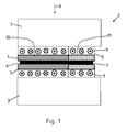
- FIG. 1 shows a tempering 1 according to the invention, wherein the tempering an upper tool 2 and a lower tool 3 has.
- the upper tool 2 and / or the lower tool 3 are movable in the direction of movement B, so that a mold cavity 6 remains between a tempering plate 4 of the upper tool 2 and a tempering plate 5 of the lower tool 3.
- a sheet metal plate 7 can be inserted, wherein the sheet metal plate 7 is then heated by the temperature control plates 4, 5 by means of conductive heating to a predetermined temperature.
- inductors 8 in the form of induction loops 9 are provided on the lower tool 3 and also shown here on the upper tool 2.
- the temperature control 4, 5 are then even heated to a desired temperature, in which case takes place from the tempering 4, 5 in abutting contact with the sheet metal plate 7, a heat conduction into the sheet metal plate 7. Consequently, the temperature of the sheet metal plate 7 itself, depending on the dwell time between upper tool 2 and lower tool 3, to a temperature up to the temperature of the temperature control 4, 5 are heated.
- both the tempering 4 of the upper tool 2 and the tempering 5 of the lower tool 3 is divided into two parts.
- a first part 10 is formed of a material and a second part 11 of a second, different material.
- the first part 10 is, for example, a material of good thermal conductivity of the tempering plate 4, 5 and the second part 11 is a material which has a low thermal conductivity in relation to the first part 10.
- the second part 11 may for example also be designed as an insulating material.
- a ceramic or else another insulating material may be used here.
- the sheet metal plate 7 can be heated to different temperatures.
- FIG. 2 shows an analogous embodiment, with respect to the right image plane no inductors 8 are provided on the second part 11 of the temperature control 4, 5.
- FIG. 3 shows a plan view of a lower tool 3 with an attached sheet metal blank 7, the outline is shown. It can be seen that the tempering 5 does not extend itself over the entire area of the lower tool 3, but only partially, based on the outer geometry of the sheet metal plate 7, dimensioned in their outer dimensions. As a result, the energy input for heating the sheet metal plate 7 is reduced to a necessary minimum. It can also be clearly seen that an induction loop 9 is formed only in the area of the first part 10 of the temperature control plate 4, 5, whereas the second part 11 of the temperature control plate 4, 5 has no inductor. The induction loop 9 itself is distributed over the first part 10 in such a way that an adaptation of the induction loop 9 to the outer dimensions of the first part 10 of the tempering plate 5 is also formed, which in turn leads to energy savings.
Landscapes
- Chemical & Material Sciences (AREA)
- Engineering & Computer Science (AREA)
- Physics & Mathematics (AREA)
- Thermal Sciences (AREA)
- Mechanical Engineering (AREA)
- Crystallography & Structural Chemistry (AREA)
- Materials Engineering (AREA)
- Metallurgy (AREA)
- Organic Chemistry (AREA)
- Heat Treatment Of Articles (AREA)
- Shaping Metal By Deep-Drawing, Or The Like (AREA)
- General Induction Heating (AREA)
Abstract
Description
- Die vorliegende Erfindung betrifft eine Warmformlinie zur Herstellung warmumgeformter und pressgehärteter Stahlblechprodukte gemäß den Merkmalen im Oberbegriff von Patentanspruch 1.
- Die vorliegende Erfindung betrifft weiterhin ein Verfahren zur Herstellung eines warmumgeformten und pressgehärteten Kraftfahrzeugbauteils gemäß den Merkmalen im Patentanspruch 12.
- Aus dem Stand der Technik ist es bekannt, Kraftfahrzeugkarosserien aus metallischen Werkstoffen herzustellen. Hierzu werden insbesondere Stahlwerkstoffe oder aber auch Leichtmetallwerkstoffe eingesetzt. Innerhalb der letzten Jahre wurden im Bereich der Stahlwerkstoffe hochfeste und höchstfeste Stähle eingesetzt, die zumindest partiell hohe Härten oder aber duktile Eigenschaften aufweisen, so dass die Festigkeit und auch die Crashperformance einer Kraftfahrzeugkarosserie gesteigert wird, bei gleichzeitiger Gewichtseinsparung.
- So ist beispielsweise aus der
DE 10 2010 004 081 B3 ein Vergütungsverfahren zum Herstellen von Stahlblechplatinen mit mindestens zwei Gefügebereichen unterschiedlicher Duktilität bekannt. Hierzu wird eine Platine zunächst in einem Ofen auf eine Temperatur homogen erwärmt und anschließend in einer Heizstation in zumindest Teilbereichen weiter auf eine Temperatur oberhalb der Austenitisierungstemperatur (AC3) erwärmt. Die Platine wird im Anschluss daran formgepresst und durch Abschrecken gehärtet. - Aufgabe der vorliegenden Erfindung ist es, ausgehend vom Stand der Technik ein Verfahren sowie eine Vorrichtung aufzuzeigen, mit denen es möglich ist, Blechbauteile mit partiell voneinander verschiedenen Festigkeitseigenschaften herzustellen, wobei die Vorrichtung einen geringen Energiebedarf, geringe Anschaffungskosten und ein flexibles Einsatzspektrum aufweist.
- Die erfindungsgemäße Aufgabe wird mit einer Warmformlinie zur Herstellung warmumgeformter und pressgehärteter Stahlblechprodukte mit den Merkmalen im Patentanspruch 1 gelöst.
- Der verfahrenstechnische Teil der Aufgabe wird weiterhin mit einem Verfahren zur Herstellung eines warmumgeformten und pressgehärteten Kraftfahrzeugbauteils gemäß den Merkmalen im Patentanspruch 12 gelöst.
- Vorteilhafte Ausführungsvarianten sind Gegenstand der abhängigen Patentansprüche.
- Die Warmformlinie zur Herstellung warmumgeformter und pressgehärteter Stahlblechprodukte, insbesondere zur Herstellung von warmumgeformten und pressgehärteten Kraftfahrzeugbauteilen, weist eine Erwärmungsvorrichtung und eine Umformvorrichtung auf. Die Erwärmungsvorrichtung wiederum ist eine Temperierstation mit einem Oberwerkzeug und einem Unterwerkzeug, wobei in der Temperierstation mindestens eine Temperierquelle zum Heizen angeordnet ist. Erfindungsgemäß sind an der Temperierstation an dem Oberwerkzeug und/oder dem Unterwerkzeug austauschbare Temperierplatten anordnenbar, wobei die Temperierquelle als Induktor ausgebildet ist und die Temperierplatten durch den Induktor erwärmbar sind.
- Erfindungsgemäß ist es somit möglich, mittels der Temperierplatten ein in die Temperierstation eingelegtes metallisches Bauteil, vorzugsweise eine Platine, zu erwärmen. Die Temperierplatten sind dabei derart an dem Oberwerkzeug und/oder Unterwerkzeug angeordnet, dass die Wärmeabgabe von der Temperierplatte an das zu erwärmende metallische Bauteil durch konduktive Wärmeübertragung, mithin durch Wärmeleitung, erfolgt. Damit nunmehr die Temperierplatten selbst auf eine Temperatur gebracht werden, die höher ist als die Umgebungstemperatur, sind in und/oder an dem Unterwerkzeug und/oder dem Oberwerkzeug Induktoren angeordnet. Mit Hilfe dieser Induktoren ist es möglich, aufgrund von induktiver Erwärmung die Temperierplatte selbst zu erwärmen. Somit ist es erfindungsgemäß möglich, dass die Temperierplatten zur Erwärmung verschiedener Bauteile an dem Oberwerkzeug und/oder dem Unterwerkzeug ausgetauscht werden können.
- Insbesondere können die Temperierplatten bei Verschleiß und/oder Abnutzung und/oder Umrüstung ausgetauscht werden, es ist jedoch auch möglich, dass die Temperierplatten derart austauschbar sind, dass sie an die verschiedenen Erfordernisse der Erwärmung anpassbar sind. So ist es beispielsweise möglich, die Temperierplatten derart auszubilden, dass sie das zu erwärmende Metallbauteil, insbesondere die Platine, nur bereichsweise kontaktieren und mithin nur bereichsweise erwärmen.
- Weiterhin bevorzugt sind die Temperierplatten selbst flächig zur Temperierung der Blechplatine ausgebildet. Hierdurch ist es insbesondere möglich, mit Hilfe der Temperierplatten eine Blechplatine zu erwärmen. Alternativ dazu ist es jedoch auch möglich, dass die Temperierplatten dreidimensional ausgebildet sind, wobei zwischen den Temperierplatten bei geschlossener Temperierstation ein Formhohlraum verbleibt. Innerhalb dieses Formhohlraumes befindet sich dann die Blechplatine. Im Rahmen der Erfindung ist unter dreidimensional ausgebildet zu verstehen, dass die Temperierplatten insbesondere eine dreidimensional verlaufende Kontakt- bzw. Oberfläche besitzen.
- Weiterhin bevorzugt ist in dem Oberwerkzeug oder in dem Unterwerkzeug jeweils mindestens ein Induktor angeordnet, wobei der Induktor des Oberwerkzeuges die Temperierplatte des Oberwerkzeuges erwärmt und der Induktor des Unterwerkzeuges die Temperierplatte des Unterwerkzeuges erwärmt, wobei vorzugsweise die Temperierplatten auf eine Temperatur von bis zu mehr als 1.000° C mit Hilfe der Induktoren erwärmbar sind. Hierdurch ist es im Rahmen der Erfindung möglich, dass ein eingelegtes metallisches Bauteil, insbesondere eine Blechplatine, die vorzugsweise aus einem Stahlwerkstoff ausgebildet ist, zumindest bereichsweise auf eine Temperatur oberhalb der Austenitisierungstemperatur erwärmbar ist. Im Rahmen der Erfindung ist es jedoch ebenfalls möglich, mit Hilfe der Induktoren gezielt eine Temperatur an der Temperierplatte einzustellen, die dann entsprechend die Blechplatine und/oder das metallische Bauteil erwärmt. So ist es beispielsweise im Rahmen der Erfindung möglich, gezielt eine Temperatur einzustellen, die die Blechplatine auf AC1 erwärmt. Im Rahmen der Erfindung ist es jedoch ebenfalls möglich, eine Temperatur an der Blechplatine derart einzustellen, dass sie auf eine gewünschte Temperatur zwischen 200° bis 1.200° erwärmbar ist. Insbesondere ist es durch Wahl der Temperierplatten und/oder durch Anordnung der Induktoren und/oder durch Regelung bzw. Steuerung der Induktoren möglich, eine in der Temperierstation eingelegte Blechplatine partiell auf voneinander verschiedene Temperaturen zu erwärmen.
- Hierzu ist vorgesehen, dass der Induktor in einer ersten alternativen Ausführungsvariante im Wesentlichen die gleiche Flächenverteilung aufweist wie die zu dem Induktor gehörige Temperierplatte. Im Rahmen der Erfindung sind somit beispielsweise mehrere Induktionsschlangen und/oder Induktionsspulen derart an dem Oberwerkzeug und/oder Unterwerkzeug verteilt oder in das Oberwerkzeug und/oder Unterwerkzeug integriert, dass sie im Wesentlichen den gleichen Flächenbereich abdecken wie die dazugehörige Temperierplatte.
- Alternativ dazu ist es jedoch auch möglich, dass der Induktor flächenmäßig verteilt kleiner ausgebildet ist als die dazugehörige Temperierplatte. In der Folge wird maßgeblich somit auch nur ein mit dem Induktor korrespondierender Flächenbereich erwärmt. Die übrigen Flächenbereiche der Temperierplatte werden zunächst nicht gezielt durch einen Induktor erwärmt. Hier tritt jedoch dann von dem erwärmten Flächenbereich eine Wärmeleitung an die nicht erwärmten Flächenbereiche der Temperierplatte auf, die im Rahmen der Erfindung jedoch insbesondere bei kurzzeitigen Erwärmungen zwischen einer Sekunde und bis zu 10 Minuten zu vernachlässigen ist.
- Weiterhin ist es im Rahmen der Erfindung möglich, dass ein an dem Oberwerkzeug und/oder Unterwerkzeug angeordneter Induktor, insbesondere abschnittsweise, mit voneinander verschiedenen Spannungen beaufschlagbar ist, so dass an den Temperierplatten abschnittsweise voneinander verschiedene Temperaturen erzeugt werden. Dies wird beispielsweise dadurch realisiert, dass verschiedene Induktorschleifen oder aber Induktorschlangen innerhalb des Unterwerkzeuges und/oder Oberwerkzeuges verlegt sind, die bereichsweise unabhängig voneinander ansteuerbar sind.
- Weiterhin bevorzugt ist es im Rahmen der Erfindung möglich zur Herstellung von partiell voneinander verschiedenen Erwärmungen, dass Temperierplatten eingesetzt werden, die mehrteilig ausgebildet sind. Die mindestens zwei voneinander verschiedenen Teile der Temperierplatte weisen dann zwei voneinander verschiedene Wärmeleiteigenschaften und/oder Werkstoffeigenschaften auf. Somit ist es beispielsweise bei zwei voneinander verschiedenen Wärmeleiteigenschaften möglich, dass die Temperierplatte durch eine homogene induktive Erwärmung auf eine im Wesentlichen gleiche Temperatur erwärmt wird, diese Temperatur jedoch aufgrund der voneinander verschiedenen Wärmeleiteigenschaften in den Bereichen unterschiedlich an die zu erwärmende Blechplatine abgibt, wodurch sich wiederum die Blechplatine unterschiedlich voneinander erwärmt.
- Alternativ dazu ist es auch möglich, dass die Temperierplatte selbst voneinander verschiedene Werkstoffeigenschaften aufweist. Hierdurch wird es wiederum ermöglicht, dass bei gleicher Einwirkung durch den Induktor die Temperierplatte sich selbst aufgrund der voneinander verschiedenen Werkstoffeigenschaften unterschiedlich erwärmt. Hierdurch wird dann bei Kontakt die entsprechende Blechplatine ebenfalls, zumindest bereichsweise, auf voneinander verschiedene Temperaturen erwärmt.
- In einer weiteren alternativen Ausführungsvariante ist es möglich, dass Bereiche erster Art und Bereiche zweiter Art mit voneinander verschiedenen Temperaturen innerhalb einer Blechplatine temperiert werden, wobei die Bereiche erster Art einen unmittelbaren Kontakt mit den Temperierplatten selbst bei geschlossener Temperierstation haben und in den Bereichen zweiter Art zwischen der Bauteiloberfläche der Blechplatine und der Temperierplatte ein Abstand ausgebildet ist, wobei der Abstand insbesondere als Luftspalt ausgebildet ist. Alternativ ist es dazu jedoch auch möglich, dass in dem Bereich zweiter Art ein Isolierwerkstoff zwischen der Bauteiloberfläche der Blechplatine und der Temperierplatte selbst angeordnet ist. Durch den Luftspalt und/oder den Isolierwerkstoff erfolgt somit wiederum eine geringere Wärmeleitung von der Temperierplatte an die Blechplatine, so dass diese mit voneinander verschiedenen Temperaturen erwärmt wird.
- Die zuvor benannten verschiedenen Ausführungsvarianten der Temperierplatten und/oder der abschnittsweisen Erwärmung der Temperierplatten sind im Rahmen der Erfindung ebenfalls beliebig untereinander kombinierbar, mit den damit einhergehenden Vorteilen. Erfindungswesentlicher Vorteil ist es, dass zumindest zwei voneinander verschiedene Bereiche in einer Platine unterschiedlich temperierbar sind. Ferner ist es möglich, insbesondere kleine lokale Flächen mit den erfindungsgemäßen Temperierplatten zu temperieren. Ganz besonders bevorzugt ist es möglich, im Bereich von Flanschen oder Durchzügen eine Temperierung vorzunehmen, insbesondere an den Flanschen oder aber den die Durchzüge berandenden Bereiche.
- Im Anschluss an die Erwärmung der Blechplatine wird diese dann in ein Umformwerkzeug transferiert, dort warmumgeformt und bevorzugt im Anschluss daran pressgehärtet.
- Im Rahmen der Erfindung ist es weiterhin möglich, dass innerhalb der Warmformlinie der Temperierstation selbst ein Ofen vorgeschaltet ist und die Metallbauteile oder die Blechplatinen in dem Ofen auf eine Temperatur vorerwärmbar sind. Beispielsweise ist es möglich, das Bauteil homogen innerhalb des Ofens auf AC1-Temperatur zu erwärmen und dann durch die Temperierstation abschnittsweise auf eine Temperatur gleich oder oberhalb des AC3-Punktes zu erwärmen. Insbesondere ist dieser Erwärmungsvorgang mit Hilfe der Temperierstation besonders kosteneffizient durchführbar, da aufgrund der induktiven Erwärmung ein nur geringer Energieeinsatz notwendig ist.
- Weiterhin bevorzugt weist die Temperierplatte auf dem Unterwerkzeug Abstandhalter auf, wobei die auf der Temperierplatte abgelegte Platine oder das metallische Bauteil von dem Abstandhalter derart abstützbar ist, dass es in einem Abstand zur Oberfläche der Temperierplatte gehalten ist. Insbesondere ist dies im Bereich zweiter Art ausgebildet, so dass hier eine gegenüber dem Bereich erster Art geringere Erwärmung stattfindet.
- Weiterhin bevorzugt weisen die Temperierplatten selbst eine Beschichtung auf, insbesondere eine zunderfeste Beschichtung. Hierdurch wird erreicht, dass über den gesamten Produktionsprozess hinweg eine annähernd gleiche Produktionsqualität verbleibt, da die Temperierplatten durch die zunderfeste Beschichtung im Wesentlichen nicht verschmutzen und somit konstant über den gesamten Produktionseinsatz hinweg die gleiche Erwärmung der voneinander verschiedenen Platinen, Blechplatinen und/oder metallischen Bauteilen durchführbar ist. Besonders bevorzugt ist die Beschichtung weiterhin hitzefest und/oder verschleißfest ausgebildet.
- Weiterhin bevorzugt ist die Temperierplatte formschlüssig an dem Oberwerkzeug und/oder dem Unterwerkzeug gekoppelt, vorzugsweise über Bolzen. Dies ermöglicht insbesondere eine derartige Kopplung, dass die Bolzen auch abschraubbar sind und/oder als Schnellverschlüsse ausgebildet sind, so dass die Temperierplatten bei anderer Dimensionierung und/oder Verschleiß leicht bei geringen Rüstzeiten austauschbar sind.
- Im Rahmen der Erfindung sind die Temperierplatten weiterhin derart bevorzugt ausgebildet, dass sie eine in den Formhohlraum ausgebildete konvexe Krümmung aufweisen. Mithin steht ein mittlerer Bereich der Temperierplatte in den Formhohlraum hinein zeigend gegenüber den zu den Seiten sich abflachenden Bereichen der Temperierplatte vor. Hierdurch wird bei Schließen der Temperierstation erreicht, dass zunächst der mittlere Bereich an der Platine anliegt und durch weiteres Schließen und/oder Pressen der Temperierstation sich dann sukzessive auch die Randbereiche an die zu erwärmende Blechplatine anlegen. Im Rahmen der Erfindung wird hierdurch ein vollflächiger Kontakt zwischen Temperierplatte und Oberfläche der zu erwärmenden Blechplatine hergestellt. Erfindungsgemäß ist es wiederum möglich, aufgrund der induktiven Erwärmung der Temperierplatte selbst hierdurch entstehende Verschiebungen von bis zu wenigen Millimetern auszugleichen, da die Temperierplatte selbst über die induktive Erwärmung kontaktlos erwärmt wird.
- Weiterer Bestandteil der vorliegenden Erfindung ist ein Verfahren zur Herstellung eines warmumgeformten und pressgehärteten Kraftfahrzeugbauteils mit einer Warmformlinie nach mindestens Anspruch 1, wobei das Verfahren durch folgende Verfahrensschritte gekennzeichnet ist:
- Erwärmen einer Platine auf eine Temperatur unter AC3,
- Transfer der Platine in eine Temperierstation,
- Erwärmen Bereiche erster Art in der Temperierstation mittels konduktiver Erwärmung auf über AC3,
- Halten Bereiche zweiter Art auf einer Temperatur unter AC3,
- Transfer der Blechplatine in ein Umformwerkzeug, Warmumformen und Presshärten.
- Im Rahmen der Erfindung ist es weiterhin möglich, dass die Platine nicht bereits vor dem Transfer in die Temperierstation auf unter AC3, sondern auf unter AC1-Temperatur erwärmt wird. Bereiche zweiter Art werden dann in der Temperierstation auf einer Temperatur unterhalb des AC1-Punktes gehalten. Erfindungswesentlicher Vorteil des Verfahrens ist insbesondere die Möglichkeit, die Temperatur gezielt an der zu erwärmenden Blechplatine und/oder dem zu erwärmenden metallischen Bauteil einzustellen und des Weiteren bei gleichzeitig geringem Energieeinsatz aufgrund der induktiven Erwärmung der Temperierplatte, wobei dann wiederum von der Temperierplatte die Erwärmung auf das zu erwärmende Bauteil mittels Konduktion erfolgt.
- Weitere Vorteile, Merkmale, Eigenschaften und Aspekte der vorliegenden Erfindung sind Bestandteil der nachfolgenden Beschreibung. Bevorzugte Ausführungsvarianten werden in den schematischen Figuren dargestellt. Diese dienen dem einfachen Verständnis der Erfindung. Es zeigen:
- Figur 1
- eine erfindungsgemäße Temperierstation mit voneinander verschiedenen Temperierplatten, wobei die Temperierplatten voneinander verschiedene Bereiche aufweisen;
- Figur 2
- die Temperierstation mit nur teilweise angeordnetem Induktor und
- Figur 3
- eine Draufsicht auf eine erfindungsgemäße Temperierplatte mit aufgelegter Platine.
- In den Figuren werden für gleiche oder ähnliche Bauteile dieselben Bezugszeichen verwendet, auch wenn eine wiederholte Beschreibung aus Vereinfachungsgründen entfällt.
-
Figur 1 zeigt eine erfindungsgemäße Temperierstation 1, wobei die Temperierstation ein Oberwerkzeug 2 und ein Unterwerkzeug 3 aufweist. Das Oberwerkzeug 2 und/oder das Unterwerkzeug 3 sind in Bewegungsrichtung B bewegbar, so dass zwischen einer Temperierplatte 4 des Oberwerkzeuges 2 und einer Temperierplatte 5 des Unterwerkzeuges 3 ein Formhohlraum 6 verbleibt. In den Formhohlraum 6 ist eine Blechplatine 7 einlegbar, wobei die Blechplatine 7 dann von den Temperierplatten 4, 5 mittels konduktiver Erwärmung auf eine vorgegebene Temperatur erwärmbar ist. - Damit die Temperierplatte 5 selbst erwärmt wird, sind an dem Unterwerkzeug 3 und auch hier dargestellt an dem Oberwerkzeug 2 Induktoren 8 in Form von Induktionsschleifen 9 vorgesehen. Mittels der Induktoren 8 sind die Temperierplatten 4, 5 selbst dann auf eine gewünschte Temperatur erwärmbar, wobei dann von den Temperierplatten 4, 5 aus bei Anlagekontakt mit der Blechplatine 7 eine Wärmeleitung in die Blechplatine 7 erfolgt. Folglich kann die Temperatur der Blechplatine 7 selbst, je nach Verweildauer zwischen Oberwerkzeug 2 und Unterwerkzeug 3, auf eine Temperatur bis zu der Temperatur der Temperierplatte 4, 5 erwärmt werden.
- Weiterhin dargestellt in
Figur 1 ist, dass sowohl die Temperierplatte 4 des Oberwerkzeuges 2 als auch die Temperierplatte 5 des Unterwerkzeuges 3 jeweils zweigeteilt ist. So ist ein erster Teil 10 aus einem Werkstoff und ein zweiter Teil 11 aus einem zweiten, davon verschiedenen Werkstoff ausgebildet. Bei dem ersten Teil 10 handelt es sich beispielsweise um einen gut wärmeleitenden Werkstoff der Temperierplatte 4, 5 und bei dem zweiten Teil 11 um einen in Relation zu dem ersten Teil 10 geringer wärmeleitenden Werkstoff. Im Rahmen der Erfindung kann der zweite Teil 11 jedoch beispielsweise auch als Isolierwerkstoff ausgebildet sein. Beispielsweise kann hier ein Keramik- oder aber auch ein anderweitiger Isolierwerkstoff eingesetzt sein. Hierdurch ist die Blechplatine 7 auf voneinander verschiedene Temperaturen erwärmbar. -
Figur 2 zeigt eine analoge Ausführungsvariante, wobei auf die rechte Bildebene bezogen keine Induktoren 8 über dem zweiten Teil 11 der Temperierplatten 4, 5 vorgesehen sind. -
Figur 3 zeigt eine Draufsicht auf ein Unterwerkzeug 3 mit aufgelegter Blechplatine 7, deren Umriss gezeigt ist. Zu erkennen ist, dass die Temperierplatte 5 sich selbst nicht über den vollständigen Bereich des Unterwerkzeuges 3 erstreckt, sondern nur abschnittsweise, an die äußere Geometrie der Blechplatine 7 angelehnt, in ihren äußeren Abmessungen dimensioniert ist. Hierdurch wird der Energieeintrag zur Erwärmung der Blechplatine 7 auf ein notwendiges Minimum reduziert. Ebenfalls gut zu erkennen ist, dass eine Induktionsschleife 9 nur im Bereich des ersten Teils 10 der Temperierplatte 4, 5 ausgebildet ist, wohingegen der zweite Teil 11 der Temperierplatte 4, 5 keinen Induktor aufweist. Die Induktionsschleife 9 selbst ist dabei derart über den ersten Teil 10 verteilt, dass auch hier eine Anpassung der Induktionsschleife 9 an die äußeren Abmessungen des ersten Teils 10 der Temperierplatte 5 ausgebildet ist, was wiederum zu einer Energieeinsparung führt. -
- 1 -
- Temperierstation
- 2 -
- Oberwerkzeug
- 3 -
- Unterwerkzeug
- 4 -
- Temperierplatte zu 2
- 5 -
- Temperierplatte zu 3
- 6 -
- Formhohlraum
- 7 -
- Blechplatine
- 8 -
- Induktor
- 9 -
- Induktionsschleife
- 10 -
- erster Teil zu 4, 5
- 11 -
- zweiter Teil zu 4, 5
- B -
- Bewegungsrichtung
Claims (13)
- Warmformlinie zur Herstellung warmumgeformter und pressgehärteter Stahlblechprodukte, insbesondere Kraftfahrzeugbauteile, aufweisend eine Erwärmungsvorrichtung und eine Umformvorrichtung, wobei die Erwärmungsvorrichtung eine Temperierstation (1) mit einem Oberwerkzeug (2) und einem Unterwerkzeug (3) aufweist und die Temperierstation (1) mindestens eine Temperierquelle zum Heizen aufweist, dadurch gekennzeichnet, dass an der Temperierstation (1) an dem Oberwerkzeug (2) und/oder dem Unterwerkzeug (3) austauschbare Temperierplatten (4, 5) anordnenbar sind und die Temperierquelle als Induktor (8) ausgebildet ist, und die Temperierplatten (4, 5) durch den Induktor (8) erwärmbar sind.
- Warmformlinie nach Anspruch 1, dadurch gekennzeichnet, dass die Temperierplatten (4, 5) flächig zur Temperierung einer Blechplatine (7) ausgebildet sind oder dass die Temperierplatten (4,5) dreidimensional ausgebildet sind, wobei zwischen den Temperierplatten (4, 5) bei geschlossener Temperierstation (1) ein Formhohlraum verbleibt.
- Warmformlinie nach Anspruch 1 oder 2, dadurch gekennzeichnet, dass in dem Oberwerkzeug (2) und in dem Unterwerkzeug (3) ein Induktor (8) angeordnet ist, wobei der Induktor (8) des Oberwerkzeuges (2) die Temperierplatte (4) des Oberwerkzeuges (2) erwärmt und der Induktor (8) des Unterwerkzeuges (3) die Temperierplatte (5) des Unterwerkzeuges (3) erwärmt, wobei vorzugsweise die Temperierplatten (4, 5) auf bis zu mehr als 1000°C erwärmbar sind.
- Warmformlinie nach einem der Ansprüche 1 bis 3, dadurch gekennzeichnet, dass der Induktor (8) im Wesentlichen die gleiche Flächenverteilung aufweist wie die zu dem Induktor (8) gehörige Temperierplatte (4, 5) oder dass der Induktor (8) kleiner ist als die zugehörige Temperierplatte (4, 5), wobei durch Aktivieren des Induktors (8) die Temperierplatte (4, 5) zumindest partiell erwärmt wird.
- Warmformlinie nach einem der vorangehenden Ansprüche, dadurch gekennzeichnet, dass der Induktor (8) abschnittsweise mit voneinander verschiedenen Spannungen beaufschlagbar ist, so dass die Temperierplatte (4, 5) abschnittsweise voneinander verschiedene Temperaturen aufweist.
- Warmformlinie nach einem der vorangehenden Ansprüche, dadurch gekennzeichnet, dass eine Temperierplatte (4, 5) mehrteilig ausgebildet ist, wobei die mindestens zwei unterschiedlichen Teile (10, 11) voneinander verschiedene Wärmeleiteigenschaften und/oder Werkstoffeigenschaften aufweisen.
- Warmformlinie nach einem der vorangehenden Ansprüche, dadurch gekennzeichnet, dass mit den Temperierplatten (4, 5) an der Blechplatine (7) Bereiche erster Art und Bereiche zweiter Art mit voneinander unterschiedlichen Temperaturen temperiert werden, wobei die Bereiche erster Art einen unmittelbaren Kontakt mit den Temperierplatten (4,5) bei geschlossener Temperierstation haben und in den Bereichen zweiter Art zwischen der Bauteiloberfläche und der Temperierplatte (4, 5) ein Abstand ausgebildet ist oder dass in den Temperierplatten (4, 5) in den Bereichen zweiter Art ein Isolierwerkstoff angeordnet ist.
- Warmformlinie nach einem der vorangehenden Ansprüche, dadurch gekennzeichnet, dass der Temperierstation (1) ein Ofen vorgeschaltet ist, wobei die Metallbauteile oder die Blechplatinen (7) in dem Ofen auf eine Temperatur vorerwärmbar sind.
- Warmformlinie nach einem der vorangehenden Ansprüche, dadurch gekennzeichnet, dass zumindest die Temperierplatte (4,5) auf dem Unterwerkzeug (3) Abstandhalter aufweist, wobei die auf der Temperierplatte (4, 5) abgelegte Blechplatine (7) oder das Metallbauteil von dem Abstandhalter abstützbar ist, insbesondere in den Bereichen zweiter Art.
- Warmformlinie nach einem der vorangehenden Ansprüche, dadurch gekennzeichnet, dass die Temperierplatte (4,5) eine Beschichtung aufweist, insbesondere eine zunderfeste Beschichtung.
- Warmformlinie nach einem der vorangehenden Ansprüche, dadurch gekennzeichnet, dass die Temperierplatte (4,5) formschlüssig an dem Oberwerkzeug (2) und/oder dem Unterwerkzeug (3) gekoppelt ist, vorzugsweise über Bolzen.
- Verfahren zur Herstellung eines warmumgeformten und pressgehärteten Kraftfahrzeugbauteils mit einer Warmformlinie nach mindestens Anspruch 1, gekennzeichnet, durch folgende Verfahrensschritte:- Erwärmen einer Blechplatine (7) auf eine Temperatur unter AC3,- Transfer der Blechplatine (7) in eine Temperierstation (1),- Erwärmen Bereiche erster Art in der Temperierstation (1) mittels konduktiver Erwärmung auf über AC3,- Halten Bereiche zweiter Art auf einer Temperatur unter AC3,- Transfer der Blechplatine (7) in ein Umformwerkzeug, Umformen und Presshärten.
- Verfahren nach Anspruch 12, dadurch gekennzeichnet, dass die Blechplatine (7) auf unter AC1 erwärmt wird, wobei der Bereich zweiter Art in der Temperierstation (1) unter AC1 gehalten wird.
Applications Claiming Priority (1)
| Application Number | Priority Date | Filing Date | Title |
|---|---|---|---|
| DE102012110650.9A DE102012110650C5 (de) | 2012-11-07 | 2012-11-07 | Warmformlinie zur Herstellung warmumgeformter und pressgehärteter Stahlblechprodukte |
Publications (3)
| Publication Number | Publication Date |
|---|---|
| EP2730346A1 true EP2730346A1 (de) | 2014-05-14 |
| EP2730346B1 EP2730346B1 (de) | 2017-05-10 |
| EP2730346B2 EP2730346B2 (de) | 2020-04-29 |
Family
ID=49226027
Family Applications (1)
| Application Number | Title | Priority Date | Filing Date |
|---|---|---|---|
| EP13184930.9A Active EP2730346B2 (de) | 2012-11-07 | 2013-09-18 | Warmformlinie zur Herstellung warmumgeformter und pressgehärteter Stahlblechprodukte |
Country Status (5)
| Country | Link |
|---|---|
| US (1) | US20140124105A1 (de) |
| EP (1) | EP2730346B2 (de) |
| CN (1) | CN103805761A (de) |
| DE (1) | DE102012110650C5 (de) |
| ES (1) | ES2627925T5 (de) |
Cited By (1)
| Publication number | Priority date | Publication date | Assignee | Title |
|---|---|---|---|---|
| EP3985133A3 (de) * | 2020-10-14 | 2022-06-15 | Benteler Automobiltechnik GmbH | Verfahren zur herstellung einer stahlplatine sowie temperierstation |
Families Citing this family (8)
| Publication number | Priority date | Publication date | Assignee | Title |
|---|---|---|---|---|
| DE102014101539B9 (de) | 2014-02-07 | 2016-08-11 | Benteler Automobiltechnik Gmbh | Warmformlinie und Verfahren zur Herstellung von warmumgeformten Blechprodukten |
| DE102014105519B4 (de) * | 2014-04-17 | 2016-05-12 | Schuler Pressen Gmbh | Vorrichtung und Verfahren zum Vorkühlen von Stahlblechplatinen |
| DE102014214027A1 (de) * | 2014-07-18 | 2016-02-18 | Bayerische Motoren Werke Aktiengesellschaft | Formwerkzeug zur Herstellung von warmumgeformten Bauteilen |
| DE102014112244A1 (de) * | 2014-08-26 | 2016-03-03 | Benteler Automobiltechnik Gmbh | Verfahren und Presse zur Herstellung wenigstens abschnittsweise gehärteter Blechbauteile |
| DE102015100100A1 (de) * | 2015-01-07 | 2016-07-07 | Thyssenkrupp Ag | Werkzeug zum Warmumformen eines Werkstücks und Verfahren zum bereichsselektiven Warmumformen eines Werkstücks |
| CN106964685A (zh) * | 2017-04-12 | 2017-07-21 | 苏州汇程精密模具有限公司 | 一种具有分段温控功能的冲切模具 |
| CN107354275A (zh) * | 2017-07-17 | 2017-11-17 | 刘路清 | 一种金属缠绕垫片处理用电热装置 |
| CN117255441A (zh) * | 2023-08-24 | 2023-12-19 | 首钢京唐钢铁联合有限责任公司 | 一种组合的板坯加热装置系统及连续铸轧生产线 |
Citations (3)
| Publication number | Priority date | Publication date | Assignee | Title |
|---|---|---|---|---|
| EP2182082A1 (de) * | 2008-10-29 | 2010-05-05 | Neue Materialien Bayreuth GmbH | Verfahren und Vorrichtung zur Temperierung eines Stahlblechkörpers |
| EP2182081A1 (de) * | 2008-10-29 | 2010-05-05 | Neue Materialien Bayreuth GmbH | Verfahren und Vorrichtung zur thermischen Behandlung eines beschichteten Stahlblechkörpers |
| DE102010004081B3 (de) | 2010-01-06 | 2011-03-24 | Benteler Automobiltechnik Gmbh | Verfahren zum Warmformen und Härten einer Platine |
Family Cites Families (12)
| Publication number | Priority date | Publication date | Assignee | Title |
|---|---|---|---|---|
| SE9602257L (sv) * | 1996-06-07 | 1997-12-08 | Plannja Hardtech Ab | Sätt att framställa ståldetalj |
| KR100646619B1 (ko) * | 2001-10-23 | 2006-11-23 | 수미도모 메탈 인더스트리즈, 리미티드 | 열간 프레스 방법, 이를 위한 도금 강철재 및 이의 제조방법 |
| DE102006058601B4 (de) † | 2006-12-11 | 2011-04-28 | Benteler Automobiltechnik Gmbh | Verfahren zur Herstellung eines Karosserie- und Fahrwerkbauteils sowie Karosserie- und Fahrwerkbauteil |
| EP2014777B1 (de) * | 2007-07-11 | 2013-01-09 | Neue Materialien Bayreuth GmbH | Verfahren sowie Vorrichtung zur thermischen Behandlung von Metallblech |
| US8017059B2 (en) * | 2007-09-13 | 2011-09-13 | The Boeing Company | Composite fabrication apparatus and method |
| US8375758B1 (en) * | 2007-09-13 | 2013-02-19 | The Boeing Company | Induction forming of metal components with slotted susceptors |
| DE102009025896A1 (de) † | 2009-06-03 | 2011-01-05 | Technische Universität Graz | Warmumformung mit Einlegematerial |
| DE102010009345B4 (de) † | 2010-02-25 | 2011-09-22 | Schuler Cartec Gmbh & Co. Kg | Verfahren und Werkzeug zur Herstellung eines Bauteils sowie ein durch Umformung hergestelltes Bauteil |
| DE102010033816A1 (de) * | 2010-06-16 | 2011-12-22 | Giw Gesellschaft Für Innovative Werkzeugsysteme Mbh | Temperiertes Werkzeug |
| DE102010049205B4 (de) † | 2010-10-13 | 2012-04-26 | Elisabeth Braun | Warmumformlinie und Verfahren zum Warmumformen von blechförmigem Material |
| DE102010048209C5 (de) * | 2010-10-15 | 2016-05-25 | Benteler Automobiltechnik Gmbh | Verfahren zur Herstellung eines warmumgeformten pressgehärteten Metallbauteils |
| DE202012000616U1 (de) † | 2012-01-24 | 2012-02-29 | Benteler Automobiltechnik Gmbh | Struktur- und/oder Karosseriebauteil für ein Kraftfahrzeug mit verbesserten Crasheigenschaften und Korrosionsschutz |
-
2012
- 2012-11-07 DE DE102012110650.9A patent/DE102012110650C5/de active Active
-
2013
- 2013-09-18 EP EP13184930.9A patent/EP2730346B2/de active Active
- 2013-09-18 CN CN201310426091.0A patent/CN103805761A/zh active Pending
- 2013-09-18 US US14/030,683 patent/US20140124105A1/en not_active Abandoned
- 2013-09-18 ES ES13184930T patent/ES2627925T5/es active Active
Patent Citations (3)
| Publication number | Priority date | Publication date | Assignee | Title |
|---|---|---|---|---|
| EP2182082A1 (de) * | 2008-10-29 | 2010-05-05 | Neue Materialien Bayreuth GmbH | Verfahren und Vorrichtung zur Temperierung eines Stahlblechkörpers |
| EP2182081A1 (de) * | 2008-10-29 | 2010-05-05 | Neue Materialien Bayreuth GmbH | Verfahren und Vorrichtung zur thermischen Behandlung eines beschichteten Stahlblechkörpers |
| DE102010004081B3 (de) | 2010-01-06 | 2011-03-24 | Benteler Automobiltechnik Gmbh | Verfahren zum Warmformen und Härten einer Platine |
Cited By (1)
| Publication number | Priority date | Publication date | Assignee | Title |
|---|---|---|---|---|
| EP3985133A3 (de) * | 2020-10-14 | 2022-06-15 | Benteler Automobiltechnik GmbH | Verfahren zur herstellung einer stahlplatine sowie temperierstation |
Also Published As
| Publication number | Publication date |
|---|---|
| US20140124105A1 (en) | 2014-05-08 |
| DE102012110650C5 (de) | 2017-12-14 |
| DE102012110650B3 (de) | 2013-11-14 |
| ES2627925T5 (es) | 2021-02-08 |
| EP2730346B2 (de) | 2020-04-29 |
| EP2730346B1 (de) | 2017-05-10 |
| CN103805761A (zh) | 2014-05-21 |
| ES2627925T3 (es) | 2017-08-01 |
Similar Documents
| Publication | Publication Date | Title |
|---|---|---|
| EP2730346B1 (de) | Warmformlinie zur Herstellung warmumgeformter und pressgehärteter Stahlblechprodukte | |
| DE102012110649B3 (de) | Warmformlinie sowie Verfahren zur Herstellung eines warmumgeformten und pressgehärteten Kraftfahrzeugbauteils | |
| EP2907881B1 (de) | Warmformlinie und Verfahren zur Herstellung von warmumgeformten Blechprodukten | |
| EP2473297B1 (de) | Verfahren und vorrichtung zur herstellung eines metallbauteils und verwendung eines solchen metallbauteils | |
| DE102005032113B3 (de) | Verfahren und Vorrichtung zum Warmumformen und partiellen Härten eines Bauteils | |
| EP2993241B1 (de) | Verfahren und presse zur herstellung wenigstens abschnittsweise gehärteter blechbauteile | |
| EP3072980B1 (de) | Verfahren und vorrichtung zur herstellung eines partiell gehärteten formteils | |
| EP2864506B1 (de) | Verfahren und vorrichtung zur herstellung eines pressgehärteten metallbauteils | |
| EP2014777B1 (de) | Verfahren sowie Vorrichtung zur thermischen Behandlung von Metallblech | |
| EP2182082B1 (de) | Verfahren und Vorrichtung zur Temperierung eines Stahlblechkörpers | |
| WO2012120123A1 (de) | Ofensystem zur gezielten wärmebehandlung von blechbauteilen | |
| DE102010011368A1 (de) | Verfahren zur Herstellung von pressgehärteten Formbauteilen | |
| DE102014111501B4 (de) | Warmumformvorrichtung und Verfahren zum Herstellen von pressgehärteten Formbauteilen aus Stahlblech | |
| DE102004007071A1 (de) | Verfahren zur Herstellung eines Bauteils durch Umformen einer Platine und Vorrichtung zur Durchführung des Verfahrens | |
| DE202010018370U1 (de) | Vorrichtung zur Herstellung von Formteilen mit mindestens zwei Gefügebereichen unterschiedlicher Duktilität | |
| DE102017109613B3 (de) | Warmformlinie mit Temperierstation sowie Verfahren zum Betreiben | |
| DE102011102167A1 (de) | Verfahren zur Herstellung eines Formbauteils mit mindestens zwei Gefügebereichen unterschiedlicher Duktilität und Erwärmungseinrichtung | |
| DE102013108972B4 (de) | Temperierstation mit Induktorerwärmung | |
| EP2679692A1 (de) | Verfahren zur Herstellung eines pressgehärteten Formbauteils aus Stahlblech | |
| DE202013103764U1 (de) | Temperierstation mit Induktorerwärmung | |
| EP3985133A2 (de) | Verfahren zur herstellung einer stahlplatine sowie temperierstation |
Legal Events
| Date | Code | Title | Description |
|---|---|---|---|
| PUAI | Public reference made under article 153(3) epc to a published international application that has entered the european phase |
Free format text: ORIGINAL CODE: 0009012 |
|
| 17P | Request for examination filed |
Effective date: 20130918 |
|
| AK | Designated contracting states |
Kind code of ref document: A1 Designated state(s): AL AT BE BG CH CY CZ DE DK EE ES FI FR GB GR HR HU IE IS IT LI LT LU LV MC MK MT NL NO PL PT RO RS SE SI SK SM TR |
|
| AX | Request for extension of the european patent |
Extension state: BA ME |
|
| R17P | Request for examination filed (corrected) |
Effective date: 20141106 |
|
| RIN1 | Information on inventor provided before grant (corrected) |
Inventor name: WULFES, DIETER Inventor name: ADELBERT, STEFAN Inventor name: TRIPPE, CARSTEN Inventor name: DANGER, ELISABETH |
|
| 17Q | First examination report despatched |
Effective date: 20160803 |
|
| REG | Reference to a national code |
Ref country code: DE Ref legal event code: R079 Ref document number: 502013007202 Country of ref document: DE Free format text: PREVIOUS MAIN CLASS: B21D0035000000 Ipc: B21D0022020000 |
|
| RIC1 | Information provided on ipc code assigned before grant |
Ipc: C21D 1/34 20060101ALI20161118BHEP Ipc: C21D 9/46 20060101ALI20161118BHEP Ipc: C21D 8/00 20060101ALI20161118BHEP Ipc: C21D 1/42 20060101ALI20161118BHEP Ipc: C21D 1/18 20060101ALI20161118BHEP Ipc: B21D 22/02 20060101AFI20161118BHEP Ipc: C21D 11/00 20060101ALI20161118BHEP Ipc: C21D 1/673 20060101ALI20161118BHEP |
|
| GRAP | Despatch of communication of intention to grant a patent |
Free format text: ORIGINAL CODE: EPIDOSNIGR1 |
|
| STAA | Information on the status of an ep patent application or granted ep patent |
Free format text: STATUS: GRANT OF PATENT IS INTENDED |
|
| INTG | Intention to grant announced |
Effective date: 20170207 |
|
| GRAS | Grant fee paid |
Free format text: ORIGINAL CODE: EPIDOSNIGR3 |
|
| GRAA | (expected) grant |
Free format text: ORIGINAL CODE: 0009210 |
|
| STAA | Information on the status of an ep patent application or granted ep patent |
Free format text: STATUS: THE PATENT HAS BEEN GRANTED |
|
| AK | Designated contracting states |
Kind code of ref document: B1 Designated state(s): AL AT BE BG CH CY CZ DE DK EE ES FI FR GB GR HR HU IE IS IT LI LT LU LV MC MK MT NL NO PL PT RO RS SE SI SK SM TR |
|
| REG | Reference to a national code |
Ref country code: GB Ref legal event code: FG4D Free format text: NOT ENGLISH |
|
| REG | Reference to a national code |
Ref country code: AT Ref legal event code: REF Ref document number: 891749 Country of ref document: AT Kind code of ref document: T Effective date: 20170515 Ref country code: CH Ref legal event code: EP |
|
| REG | Reference to a national code |
Ref country code: IE Ref legal event code: FG4D Free format text: LANGUAGE OF EP DOCUMENT: GERMAN |
|
| REG | Reference to a national code |
Ref country code: DE Ref legal event code: R096 Ref document number: 502013007202 Country of ref document: DE |
|
| REG | Reference to a national code |
Ref country code: ES Ref legal event code: FG2A Ref document number: 2627925 Country of ref document: ES Kind code of ref document: T3 Effective date: 20170801 |
|
| REG | Reference to a national code |
Ref country code: NL Ref legal event code: MP Effective date: 20170510 |
|
| REG | Reference to a national code |
Ref country code: LT Ref legal event code: MG4D |
|
| REG | Reference to a national code |
Ref country code: FR Ref legal event code: PLFP Year of fee payment: 5 |
|
| PG25 | Lapsed in a contracting state [announced via postgrant information from national office to epo] |
Ref country code: HR Free format text: LAPSE BECAUSE OF FAILURE TO SUBMIT A TRANSLATION OF THE DESCRIPTION OR TO PAY THE FEE WITHIN THE PRESCRIBED TIME-LIMIT Effective date: 20170510 Ref country code: GR Free format text: LAPSE BECAUSE OF FAILURE TO SUBMIT A TRANSLATION OF THE DESCRIPTION OR TO PAY THE FEE WITHIN THE PRESCRIBED TIME-LIMIT Effective date: 20170811 Ref country code: FI Free format text: LAPSE BECAUSE OF FAILURE TO SUBMIT A TRANSLATION OF THE DESCRIPTION OR TO PAY THE FEE WITHIN THE PRESCRIBED TIME-LIMIT Effective date: 20170510 Ref country code: NO Free format text: LAPSE BECAUSE OF FAILURE TO SUBMIT A TRANSLATION OF THE DESCRIPTION OR TO PAY THE FEE WITHIN THE PRESCRIBED TIME-LIMIT Effective date: 20170810 Ref country code: LT Free format text: LAPSE BECAUSE OF FAILURE TO SUBMIT A TRANSLATION OF THE DESCRIPTION OR TO PAY THE FEE WITHIN THE PRESCRIBED TIME-LIMIT Effective date: 20170510 |
|
| PG25 | Lapsed in a contracting state [announced via postgrant information from national office to epo] |
Ref country code: PL Free format text: LAPSE BECAUSE OF FAILURE TO SUBMIT A TRANSLATION OF THE DESCRIPTION OR TO PAY THE FEE WITHIN THE PRESCRIBED TIME-LIMIT Effective date: 20170510 Ref country code: SE Free format text: LAPSE BECAUSE OF FAILURE TO SUBMIT A TRANSLATION OF THE DESCRIPTION OR TO PAY THE FEE WITHIN THE PRESCRIBED TIME-LIMIT Effective date: 20170510 Ref country code: NL Free format text: LAPSE BECAUSE OF FAILURE TO SUBMIT A TRANSLATION OF THE DESCRIPTION OR TO PAY THE FEE WITHIN THE PRESCRIBED TIME-LIMIT Effective date: 20170510 Ref country code: IS Free format text: LAPSE BECAUSE OF FAILURE TO SUBMIT A TRANSLATION OF THE DESCRIPTION OR TO PAY THE FEE WITHIN THE PRESCRIBED TIME-LIMIT Effective date: 20170910 Ref country code: RS Free format text: LAPSE BECAUSE OF FAILURE TO SUBMIT A TRANSLATION OF THE DESCRIPTION OR TO PAY THE FEE WITHIN THE PRESCRIBED TIME-LIMIT Effective date: 20170510 Ref country code: LV Free format text: LAPSE BECAUSE OF FAILURE TO SUBMIT A TRANSLATION OF THE DESCRIPTION OR TO PAY THE FEE WITHIN THE PRESCRIBED TIME-LIMIT Effective date: 20170510 Ref country code: BG Free format text: LAPSE BECAUSE OF FAILURE TO SUBMIT A TRANSLATION OF THE DESCRIPTION OR TO PAY THE FEE WITHIN THE PRESCRIBED TIME-LIMIT Effective date: 20170810 |
|
| REG | Reference to a national code |
Ref country code: DE Ref legal event code: R026 Ref document number: 502013007202 Country of ref document: DE |
|
| PLBI | Opposition filed |
Free format text: ORIGINAL CODE: 0009260 |
|
| PG25 | Lapsed in a contracting state [announced via postgrant information from national office to epo] |
Ref country code: DK Free format text: LAPSE BECAUSE OF FAILURE TO SUBMIT A TRANSLATION OF THE DESCRIPTION OR TO PAY THE FEE WITHIN THE PRESCRIBED TIME-LIMIT Effective date: 20170510 Ref country code: SK Free format text: LAPSE BECAUSE OF FAILURE TO SUBMIT A TRANSLATION OF THE DESCRIPTION OR TO PAY THE FEE WITHIN THE PRESCRIBED TIME-LIMIT Effective date: 20170510 Ref country code: RO Free format text: LAPSE BECAUSE OF FAILURE TO SUBMIT A TRANSLATION OF THE DESCRIPTION OR TO PAY THE FEE WITHIN THE PRESCRIBED TIME-LIMIT Effective date: 20170510 Ref country code: CZ Free format text: LAPSE BECAUSE OF FAILURE TO SUBMIT A TRANSLATION OF THE DESCRIPTION OR TO PAY THE FEE WITHIN THE PRESCRIBED TIME-LIMIT Effective date: 20170510 Ref country code: EE Free format text: LAPSE BECAUSE OF FAILURE TO SUBMIT A TRANSLATION OF THE DESCRIPTION OR TO PAY THE FEE WITHIN THE PRESCRIBED TIME-LIMIT Effective date: 20170510 |
|
| 26 | Opposition filed |
Opponent name: SCHULER PRESSEN GMBH Effective date: 20180116 |
|
| PLAX | Notice of opposition and request to file observation + time limit sent |
Free format text: ORIGINAL CODE: EPIDOSNOBS2 |
|
| PG25 | Lapsed in a contracting state [announced via postgrant information from national office to epo] |
Ref country code: IT Free format text: LAPSE BECAUSE OF FAILURE TO SUBMIT A TRANSLATION OF THE DESCRIPTION OR TO PAY THE FEE WITHIN THE PRESCRIBED TIME-LIMIT Effective date: 20170510 Ref country code: SM Free format text: LAPSE BECAUSE OF FAILURE TO SUBMIT A TRANSLATION OF THE DESCRIPTION OR TO PAY THE FEE WITHIN THE PRESCRIBED TIME-LIMIT Effective date: 20170510 |
|
| REG | Reference to a national code |
Ref country code: CH Ref legal event code: PL |
|
| PLAB | Opposition data, opponent's data or that of the opponent's representative modified |
Free format text: ORIGINAL CODE: 0009299OPPO |
|
| PG25 | Lapsed in a contracting state [announced via postgrant information from national office to epo] |
Ref country code: MC Free format text: LAPSE BECAUSE OF FAILURE TO SUBMIT A TRANSLATION OF THE DESCRIPTION OR TO PAY THE FEE WITHIN THE PRESCRIBED TIME-LIMIT Effective date: 20170510 Ref country code: SI Free format text: LAPSE BECAUSE OF FAILURE TO SUBMIT A TRANSLATION OF THE DESCRIPTION OR TO PAY THE FEE WITHIN THE PRESCRIBED TIME-LIMIT Effective date: 20170510 |
|
| R26 | Opposition filed (corrected) |
Opponent name: SCHULER PRESSEN GMBH Effective date: 20180116 |
|
| PLBB | Reply of patent proprietor to notice(s) of opposition received |
Free format text: ORIGINAL CODE: EPIDOSNOBS3 |
|
| REG | Reference to a national code |
Ref country code: IE Ref legal event code: MM4A |
|
| REG | Reference to a national code |
Ref country code: BE Ref legal event code: MM Effective date: 20170930 |
|
| PG25 | Lapsed in a contracting state [announced via postgrant information from national office to epo] |
Ref country code: LU Free format text: LAPSE BECAUSE OF NON-PAYMENT OF DUE FEES Effective date: 20170918 |
|
| PG25 | Lapsed in a contracting state [announced via postgrant information from national office to epo] |
Ref country code: IE Free format text: LAPSE BECAUSE OF NON-PAYMENT OF DUE FEES Effective date: 20170918 Ref country code: CH Free format text: LAPSE BECAUSE OF NON-PAYMENT OF DUE FEES Effective date: 20170930 Ref country code: LI Free format text: LAPSE BECAUSE OF NON-PAYMENT OF DUE FEES Effective date: 20170930 |
|
| PG25 | Lapsed in a contracting state [announced via postgrant information from national office to epo] |
Ref country code: BE Free format text: LAPSE BECAUSE OF NON-PAYMENT OF DUE FEES Effective date: 20170930 |
|
| REG | Reference to a national code |
Ref country code: FR Ref legal event code: PLFP Year of fee payment: 6 |
|
| PG25 | Lapsed in a contracting state [announced via postgrant information from national office to epo] |
Ref country code: MT Free format text: LAPSE BECAUSE OF FAILURE TO SUBMIT A TRANSLATION OF THE DESCRIPTION OR TO PAY THE FEE WITHIN THE PRESCRIBED TIME-LIMIT Effective date: 20170510 |
|
| PG25 | Lapsed in a contracting state [announced via postgrant information from national office to epo] |
Ref country code: HU Free format text: LAPSE BECAUSE OF FAILURE TO SUBMIT A TRANSLATION OF THE DESCRIPTION OR TO PAY THE FEE WITHIN THE PRESCRIBED TIME-LIMIT; INVALID AB INITIO Effective date: 20130918 |
|
| PG25 | Lapsed in a contracting state [announced via postgrant information from national office to epo] |
Ref country code: CY Free format text: LAPSE BECAUSE OF NON-PAYMENT OF DUE FEES Effective date: 20170510 |
|
| REG | Reference to a national code |
Ref country code: AT Ref legal event code: MM01 Ref document number: 891749 Country of ref document: AT Kind code of ref document: T Effective date: 20180918 |
|
| PG25 | Lapsed in a contracting state [announced via postgrant information from national office to epo] |
Ref country code: MK Free format text: LAPSE BECAUSE OF FAILURE TO SUBMIT A TRANSLATION OF THE DESCRIPTION OR TO PAY THE FEE WITHIN THE PRESCRIBED TIME-LIMIT Effective date: 20170510 |
|
| PGFP | Annual fee paid to national office [announced via postgrant information from national office to epo] |
Ref country code: GB Payment date: 20190920 Year of fee payment: 7 |
|
| PG25 | Lapsed in a contracting state [announced via postgrant information from national office to epo] |
Ref country code: AT Free format text: LAPSE BECAUSE OF NON-PAYMENT OF DUE FEES Effective date: 20180918 |
|
| PUAH | Patent maintained in amended form |
Free format text: ORIGINAL CODE: 0009272 |
|
| STAA | Information on the status of an ep patent application or granted ep patent |
Free format text: STATUS: PATENT MAINTAINED AS AMENDED |
|
| PG25 | Lapsed in a contracting state [announced via postgrant information from national office to epo] |
Ref country code: TR Free format text: LAPSE BECAUSE OF FAILURE TO SUBMIT A TRANSLATION OF THE DESCRIPTION OR TO PAY THE FEE WITHIN THE PRESCRIBED TIME-LIMIT Effective date: 20170510 |
|
| 27A | Patent maintained in amended form |
Effective date: 20200429 |
|
| AK | Designated contracting states |
Kind code of ref document: B2 Designated state(s): AL AT BE BG CH CY CZ DE DK EE ES FI FR GB GR HR HU IE IS IT LI LT LU LV MC MK MT NL NO PL PT RO RS SE SI SK SM TR |
|
| REG | Reference to a national code |
Ref country code: DE Ref legal event code: R102 Ref document number: 502013007202 Country of ref document: DE |
|
| PG25 | Lapsed in a contracting state [announced via postgrant information from national office to epo] |
Ref country code: PT Free format text: LAPSE BECAUSE OF FAILURE TO SUBMIT A TRANSLATION OF THE DESCRIPTION OR TO PAY THE FEE WITHIN THE PRESCRIBED TIME-LIMIT Effective date: 20170510 |
|
| PG25 | Lapsed in a contracting state [announced via postgrant information from national office to epo] |
Ref country code: AL Free format text: LAPSE BECAUSE OF FAILURE TO SUBMIT A TRANSLATION OF THE DESCRIPTION OR TO PAY THE FEE WITHIN THE PRESCRIBED TIME-LIMIT Effective date: 20170510 |
|
| REG | Reference to a national code |
Ref country code: ES Ref legal event code: DC2A Ref document number: 2627925 Country of ref document: ES Kind code of ref document: T5 Effective date: 20210208 |
|
| GBPC | Gb: european patent ceased through non-payment of renewal fee |
Effective date: 20200918 |
|
| PG25 | Lapsed in a contracting state [announced via postgrant information from national office to epo] |
Ref country code: GB Free format text: LAPSE BECAUSE OF NON-PAYMENT OF DUE FEES Effective date: 20200918 |
|
| PGFP | Annual fee paid to national office [announced via postgrant information from national office to epo] |
Ref country code: FR Payment date: 20240925 Year of fee payment: 12 |
|
| PGFP | Annual fee paid to national office [announced via postgrant information from national office to epo] |
Ref country code: DE Payment date: 20250929 Year of fee payment: 13 |
|
| PGFP | Annual fee paid to national office [announced via postgrant information from national office to epo] |
Ref country code: ES Payment date: 20251028 Year of fee payment: 13 |