EP2730258A1 - Bite splint - Google Patents
Bite splint Download PDFInfo
- Publication number
- EP2730258A1 EP2730258A1 EP12192020.1A EP12192020A EP2730258A1 EP 2730258 A1 EP2730258 A1 EP 2730258A1 EP 12192020 A EP12192020 A EP 12192020A EP 2730258 A1 EP2730258 A1 EP 2730258A1
- Authority
- EP
- European Patent Office
- Prior art keywords
- wall
- splint
- bite splint
- bite
- base element
- Prior art date
- Legal status (The legal status is an assumption and is not a legal conclusion. Google has not performed a legal analysis and makes no representation as to the accuracy of the status listed.)
- Granted
Links
Images


Classifications
-
- A—HUMAN NECESSITIES
- A61—MEDICAL OR VETERINARY SCIENCE; HYGIENE
- A61F—FILTERS IMPLANTABLE INTO BLOOD VESSELS; PROSTHESES; DEVICES PROVIDING PATENCY TO, OR PREVENTING COLLAPSING OF, TUBULAR STRUCTURES OF THE BODY, e.g. STENTS; ORTHOPAEDIC, NURSING OR CONTRACEPTIVE DEVICES; FOMENTATION; TREATMENT OR PROTECTION OF EYES OR EARS; BANDAGES, DRESSINGS OR ABSORBENT PADS; FIRST-AID KITS
- A61F5/00—Orthopaedic methods or devices for non-surgical treatment of bones or joints; Nursing devices ; Anti-rape devices
- A61F5/56—Devices for preventing snoring
- A61F5/566—Intra-oral devices
Definitions
- the present invention relates to a bite splint for use in dental field according to the preamble of claim 1.
- Anterior bite splints also called deprogrammers, are known to be used to reduce strain in the muscles of mastication by activating nociceptive trigeminale inhibition.
- nociceptive trigeminale inhibition When too much pressure is put on the mandibular incisor teeth of an individual, the neural relaxation reflex is activated and masticatory muscles relax as a result thereof.
- tension or migraine headaches due to tense muscles can be reduced or even prevented by wearing a bite splint.
- Such splints are also frequently helpful to reduce pain in the tempomandibular joints or other head and neck pain associated with craniomandibular dysfunction.
- An object of the present invention is to provide an improved anterior bite splint.
- the invention relates to a bite splint having a tunnel-like recess.
- the recess is defined by two walls being connected to each other via a base element and wherein the first wall protrudes straight downwards from the base element as for instance approximately at 90°. Further, at least a part of an upper surface of the second wall is inclined downwards with respect to an upper surface of the base element.
- a saddle-like platform extends obliquely from the base element in an upwards direction and wherein the second wall is inclined downwards with respect to the upper surface of the platform.
- a pedestal-like platform protrudes from the base element to the opposite side of the first wall.
- the bite splint is a maxillary splint or a mandible splint.
- the bite splint can be adapted to manifold tooth positions, i.e. to standard occlusions but also to anomalous occlusions of a patient.
- an inclination angle between the upper surface of the second wall and the upper surface of the base element is about 20° to 30°, preferably 22° to 28°, preferably 24° to 26° or 25°.
- a further inclination angle of the tunnel-like recess formed between the first wall and the second wall is about 20° to 40° or about 35°.
- the bite contact surface is extensive enough, i.e. has sufficient ventral extension to achieve contact between the upper incisor teeth and the bite splint when used as a mandible splint for example.
- the upper lip is prevented from becoming trapped by or hanging onto the second wall of the bite splint and thus, prevents dislodgement of the bite splint from its designated wearing position by the perioral musculature.
- the bite splint is dimensioned in its width to be fitted onto at least two adjacent teeth of an individual.
- the height of the first wall is about 2cm.
- the bite splint provides enough material to cover cervical areas of the teeth.
- good retention is achieved by providing adequate support of the relining material.
- the relining material being inserted into the recess is also not visible from the front, and advantage since many relining materials have a tendency to stain.
- At least a part of the second wall is thicker than the first wall.
- the adaptation of the bite splint can easily be optimized by selectively grinding the internal aspect of the second wall e.g. to adapt the bite splint individually to a teeth of an individual e.g. with malaligned or rotated incisor teeth.
- the second wall is of a wall thickness of about 2mm to 3mm.
- the base element or the further base element is of the same thickness as the second wall.
- the width of the first wall is shorter than the width of the second wall with a wing-like element at the endings, such as the lateral aspects of the second wall.
- the bite splint can quickly be adapted to establish contact with the canine teeth of the maxilla. This allows distribution of loads originating from biting on the bite splint over up to six adjacent teeth.
- an inner surface or the inside of the recess is rough. Thereby, adhesion of relining material to the inner surface of the recess is improved.
- the roughness of the inner surface is 20 ⁇ m Ra to 40 ⁇ m Ra.
- the bite splint is semi-transparent or transparent.
- the bite splint easily can be adapted since the dentist can see the teeth through the splint and thus, can verify correct fitting of the splint.
- the edges of the bite splint are rounded such as for instance the outer edges of the bite splint, and wherein bite contact surfaces of the bite splint are smooth.
- At least one of the walls comprises a notch at its edge such that the notch demonstrates e.g. a curved notch.
- the labial frenulum or the lingual frenulum, respectively can be accommodated without causing discomfort to the individual.
- the bite splint is out of a material of at least one of liquid crystal polymers, polyamide, cyclooefin copolymer, polyester copolymer, preferably transparent polyester copolymer.
- the bite splint demonstrates an increased life expectancy.
- the bite splint according to the present invention allows adaptation in the mouth of the patient without a dental laboratory.
- FIG 1 schematically, a bite splint 1 according to the present invention in isometric view is depicted.
- the tunnel-like bite splint 1 is defined by two walls 3, 5 which are connected to each other via a base element 7.
- the shape of the bite splint 1 is curved according to an average dental arch form.
- a tunnel-like recess 19 of the bite splint 1 is substantially U-shaped.
- the first wall 3 protrudes downwards from the base element 7 in substantially straight manner such as for instance approximately at 90°.
- Each of the endings of the second wall 5 comprises a wing-like element 9.
- the width W1 of the first wall 3 is shorter than the width W2 of the second wall 5 (see figure 2 ).
- the wing-like element 9 is arranged bent off from the endings of the first side wall 5 in opposite direction of the first wall 3.
- An upper surface 11 of the base element 7 and at least a part of an upper surface 13 (see figure 3 ) of the second wall 5 form a first bite contact surface 15.
- a region of the upper surface 13 of the second wall 5 is extended towards the opposite side of the first wall 3 forming a platform 17.
- An upper surface 27 of the platform 17 is a second bite contact surface.
- the platform 17 is arranged in the middle part of the bite splint 1.
- the platform 17 is of a pedestal-like or socket-like shape.
- the depth D1 of the pedestal-like platform 17 is about a third of the depth D2 of the base element 7.
- the tunnel-like recess 19 for receiving the teeth of an individual is depicted in figure 1 .
- the recess 19 is of a curved shape suitable to receive teeth of nearly any individual.
- the outer edges of the bite splint 1 are rounded and the bite contact surfaces 15, 27 of the bite splint 1 are smooth. It is also conceivable the all surfaces with the exception of an inner surface of the tunnel-like recess 19 are smooth.
- the inner surface of the tunnel-like surface is rough.
- FIG 2 schematically, a bottom view according to figure 1 is shown.
- the tunnel-like recess 19 is of a concave shape.
- the width W1 of the first wall 3 is shorter than the width W2 of the second wall 5.
- the platform 17 comprises a hollow 21 which is open to a bottom side of the bite splint 1.
- the first wall 3 demonstrates a rounded notch 31 in its middle of the width W1.
- the rounded notch 31 serves for reception of the labial frenulum when used a maxillary splint.
- Each of the endings of the second wall 5 comprises the wing-like element 9.
- the walls 3, 5 are of a definite thickness.
- the thickness of the base element 7 is of a definite thickness.
- the thickness of the first wall 3, of the second wall 5 and of the base element 7 is thick enough such that the dentist can adapt the bite splint according to an individual tooth position by grinding down surplus material of the bite splint.
- the wing-like element 9 can completely be removed for example, if required. Thus, there is no need to add extension material. Removing portions of the splint when they are not required for the individual situation is fast and simple, adding material to extend the splint is technically difficult and time-consuming.
- FIG 3 schematically, a section A-A according to figure 2 is depicted.
- the first wall 3 protrudes downwards from the base element 7 in almost straight manner, i.e. the upper surface 11 of the base element 7 is nearly perpendicular to the outer side 12 of the first wall 3.
- the first wall 3 is tapered towards its bottom side 23.
- the base element 7 comprises the horizontal flattened upper surface 11 being a part of the first bite contact surface 15. At least a further part of the upper surface 13 of the second wall 5 is inclined downwards with respect to the upper surface 11 of the base element 7, the upper surface 13 being also a part of the first bite contact surface 15.
- the free ending 25 of the second wall 5 is bent or angled off from the rest of the second wall 5 such that the free ending 25 protrudes downwardly in straight manner such that the free ending 25 forms a wing-like extension.
- the wing-like extension 25 of the second wall maintains the same vertical angulation, and terminates downward in a straight line.
- the upper surface 11 of the base element 7 and at least a part of the upper surface 13 of the second wall 5 form the first bite contact surface 15 together.
- the upper surface 11 of the base element 7 and the upper surface 13 of the second wall 5 are arranged adjacent to each other.
- An inclination angle ⁇ 1 between the upper surface 13 of the inclined second wall 5 and the plane upper surface 11 of the base element 7 is about 20° to 30°, preferably 22° to 28°, preferably 24° to 26° or 25°.
- a further inclination angle ⁇ 2 of the further tunnel-like recess 19 is formed between the first wall 3 and the free ending 25 of the second wall 5. This further inclination angle ⁇ 2 is about 20° to 40° or about 35°.
- the overall width of the bite splint 1 is dimensioned such to cover at least two teeth adjacent to each other, e.g. two incisors. It is also conceivable to utilize more than two teeth, e.g. four incisors teeth or e.g. four incisor teeth including the canine teeth of the maxilla. In this case, the wing-like elements 9 contact the maxillary canine teeth only from the palatal side. The upper side of the respective maxillary canine remains uncovered. This allows providing an individual maxilla bite splint based on one single size. This allows adaptation to different arch forms without the necessity to have selection of different sizes. This maxillary bite splint is designed for adaptation in the mouth of the patient without a dental laboratory.
- the pedestal-like platform 17 surmounts the inclined upper surface 13 of the second wall 5, i.e. the upper surface 27 of the pedestal 17 is less inclined compared to the upper surface 13 of the second wall 5. This allows providing a bite splint of a required breaking strength with a high resistance to fracture during use.
- the upper surface 27 of the pedestal-like platform 17 represents a second bite contact surface.
- a side wall 29 of the pedestal-like platform 17 is depicted in figure 3 .
- the wing-like element 9 of the second wall 5 is also depicted in figure 3 .
- FIG 4 a further bite splint 1' according to the present invention in isometric view is depicted.
- the further tunnel-like bite splint 1' is defined by two further walls 3', 5' which are connected to each other via a further base element 7'.
- the shape of the further bite splint 1' is curved according to the average arch form of patients.
- a further tunnel-like recess 19' of the further bite splint 1' is substantially U-shaped.
- the further first wall 3' protrudes downwards from the further base element 7' in substantially straight manner, such as for instants approximately at 90°.
- a further platform 17' protrudes obliquely from the further base element 7' in upwards direction in extension of the further second wall 5'.
- the further platform 17' is saddle-like or disk-like and protrudes upwardly from the further base element 7' or is an extension of the further second wall 5', respectively.
- the further, bite splint 1' can either be used as a mandible or a maxillary splint. It's use in the maxillary arch is favourable when the upper front incisor teeth vertically cover the lower front incisor teeth, i.e.
- the upper surface 27' of the saddle-like or disk-like platform 17' is dimensioned such in its length L (see figure 5 ) to be suitable for teeth having such a type of class II occlusion.
- the first wall 3' comprises a V-shaped or rounded groove 31' at its bottom side 23'.
- the V-shaped or rounded groove 31 serves for reception of the lingual frenulum when used as a mandible splint.
- the further second wall 5' comprises a further V-shaped or rounded groove 33' at its bottom side 35'.
- the further V-shaped or rounded groove 33' of the further second wall 5' serves for reception of the labial frenulum when used as a mandible splint.
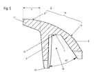
- FIG 5 schematically, a cross section of the further bite splint 1' according to the present invention is shown.
- the saddle-like or the disk-like platform 17' protrudes from the further base element 7', or is an extension of the further second wall 5', respectively.
- a further upper surface 27' of the saddle-like or disk-like platform 17' and a further upper surface 13' of the further second wall 5' form a third bite contact surface 14.
- the third bite contact face 14 is of a curved shape. Edges of the further bite splint 1' are rounded and the third contact face 14 of the further bite splint 1' is smooth. It is also conceivable the all surfaces with the exception of an inner surface or the inside of the further tunnel-like recess 19' are smooth.
- the inner surface of the tunnel-like surface is rough.
- the further walls 3', 5' are of a definite thickness.
- the thickness of the further base element 7' is also of a definite thickness.
- the thickness of the further first wall 3', of the further second wall 5' and of the further base element 7' is thick enough such that the dentist can adapt the bite splint according to an individual tooth position by grinding down surplus material of the bite splint.
- Adding of extension material is technically difficult and is time-consuming.
- a third inclination angle ⁇ 2' of the further tunnel-like recess 19' is formed between the further first wall 3' and the further second wall 5'. This third inclination angle ⁇ 2' is about 20° to 40° or about 35°.
- a top 37 of the tunnel-like recess 19' is flattened.
- the further first wall 3' is tapered towards its bottom side 23'.
Landscapes
- Health & Medical Sciences (AREA)
- Otolaryngology (AREA)
- Pulmonology (AREA)
- Nursing (AREA)
- Orthopedic Medicine & Surgery (AREA)
- Engineering & Computer Science (AREA)
- Biomedical Technology (AREA)
- Heart & Thoracic Surgery (AREA)
- Vascular Medicine (AREA)
- Life Sciences & Earth Sciences (AREA)
- Animal Behavior & Ethology (AREA)
- General Health & Medical Sciences (AREA)
- Public Health (AREA)
- Veterinary Medicine (AREA)
- Dental Tools And Instruments Or Auxiliary Dental Instruments (AREA)
- Orthopedics, Nursing, And Contraception (AREA)
Abstract
Description
- The present invention relates to a bite splint for use in dental field according to the preamble of
claim 1. - Anterior bite splints, also called deprogrammers, are known to be used to reduce strain in the muscles of mastication by activating nociceptive trigeminale inhibition. When too much pressure is put on the mandibular incisor teeth of an individual, the neural relaxation reflex is activated and masticatory muscles relax as a result thereof. Thus, tension or migraine headaches due to tense muscles can be reduced or even prevented by wearing a bite splint. Such splints are also frequently helpful to reduce pain in the tempomandibular joints or other head and neck pain associated with craniomandibular dysfunction.
- An object of the present invention is to provide an improved anterior bite splint.
- This objective is achieved by the features given in the characterizing part of
claim 1. Further embodiments of the invention are given in dependant claims. - The invention relates to a bite splint having a tunnel-like recess. The recess is defined by two walls being connected to each other via a base element and wherein the first wall protrudes straight downwards from the base element as for instance approximately at 90°. Further, at least a part of an upper surface of the second wall is inclined downwards with respect to an upper surface of the base element. Thereby, pathological load distribution leading to unwanted movement or tipping of teeth is prevented since only axial load is exerted onto the teeth during clenching or pressing.
- In one embodiment, a saddle-like platform extends obliquely from the base element in an upwards direction and wherein the second wall is inclined downwards with respect to the upper surface of the platform.
- Thereby, a bite contact surface is ensured even for severe malocclusions of Class II
Division 1 according to Edward Angle's classification method, where a significant overjet is present. Or in other words, where the mandibular arch is smaller than the maxillary arch by a significant degree. - In one embodiment, a pedestal-like platform protrudes from the base element to the opposite side of the first wall. Thereby, a sufficiently large contact surface for contacting the opposite mandible incisors is ensured even in case the individual exhibits extensive lateral movements of the mandible.
- In one embodiment, the bite splint is a maxillary splint or a mandible splint.
- Thereby, the bite splint can be adapted to manifold tooth positions, i.e. to standard occlusions but also to anomalous occlusions of a patient.
- In one embodiment, an inclination angle between the upper surface of the second wall and the upper surface of the base element is about 20° to 30°, preferably 22° to 28°, preferably 24° to 26° or 25°.
- Thereby, pathological load distribution leading to unwanted displacement of teeth is prevented since only axial load is exerted onto the bite contact surface when teeth are clenched.
- In one embodiment, a further inclination angle of the tunnel-like recess formed between the first wall and the second wall is about 20° to 40° or about 35°.
- Thereby, the bite contact surface is extensive enough, i.e. has sufficient ventral extension to achieve contact between the upper incisor teeth and the bite splint when used as a mandible splint for example. When used as a maxilla splint for example, the upper lip is prevented from becoming trapped by or hanging onto the second wall of the bite splint and thus, prevents dislodgement of the bite splint from its designated wearing position by the perioral musculature.
- In one embodiment, the bite splint is dimensioned in its width to be fitted onto at least two adjacent teeth of an individual.
- Thereby, retention of the bite splint is ensured when inserted into the mouth of an individual since sufficient undercuts and interproximal contours are available.
- In one embodiment, the height of the first wall is about 2cm.
- Thereby, the bite splint provides enough material to cover cervical areas of the teeth. Thus, good retention is achieved by providing adequate support of the relining material. Furthermore, the relining material being inserted into the recess is also not visible from the front, and advantage since many relining materials have a tendency to stain.
- In one embodiment, at least a part of the second wall is thicker than the first wall.
- Thereby, the adaptation of the bite splint can easily be optimized by selectively grinding the internal aspect of the second wall e.g. to adapt the bite splint individually to a teeth of an individual e.g. with malaligned or rotated incisor teeth.
- In one embodiment, the second wall is of a wall thickness of about 2mm to 3mm.
- This allows adapting the bite splint to manifold tooth positions within a very short time without the need of adding additional structural material for extension of the bite splint.
- In one embodiment, the base element or the further base element is of the same thickness as the second wall.
- In one embodiment, the width of the first wall is shorter than the width of the second wall with a wing-like element at the endings, such as the lateral aspects of the second wall.
- Thereby, the bite splint can quickly be adapted to establish contact with the canine teeth of the maxilla. This allows distribution of loads originating from biting on the bite splint over up to six adjacent teeth.
- In one embodiment, an inner surface or the inside of the recess is rough. Thereby, adhesion of relining material to the inner surface of the recess is improved.
- In one embodiment, the roughness of the inner surface is 20µm Ra to 40µm Ra.
- In one embodiment, the bite splint is semi-transparent or transparent. Thereby, the bite splint easily can be adapted since the dentist can see the teeth through the splint and thus, can verify correct fitting of the splint.
- In one embodiment, the edges of the bite splint are rounded such as for instance the outer edges of the bite splint, and wherein bite contact surfaces of the bite splint are smooth. Thereby, reducing the time requirement for finishing and polishing of the bite splint is achieved.
- In one embodiment, at least one of the walls comprises a notch at its edge such that the notch demonstrates e.g. a curved notch.
- Thereby, the labial frenulum or the lingual frenulum, respectively, can be accommodated without causing discomfort to the individual.
- In one embodiment, the bite splint is out of a material of at least one of liquid crystal polymers, polyamide, cyclooefin copolymer, polyester copolymer, preferably transparent polyester copolymer.
- Thereby, sufficient fracture strength is ensured to resist high bite forces. Furthermore, antagonist teeth in contact with the bite splint are protected from attrition since the materials above mentioned have a low friction coefficient and a low abrasion coefficient. Furthermore, the materials afore-mentioned are resistant to acids, monomers, and cleaning agents. Thus, the bite splint demonstrates an increased life expectancy.
- Furthermore, the bite splint according to the present invention allows adaptation in the mouth of the patient without a dental laboratory.
- The present invention is further explained with the aid of exemplified embodiments, which are shown in the figures. There is shown in:
-
fig. 1 , schematically, a bite splint according to the present invention in isometric view; -
fig. 2 , schematically, a bottom view according tofigure 1 ; -
fig. 3 , schematically, a section A-A according tofigure 2 ; -
fig. 4 , schematically, a further bite splint according to the present invention in isometric view; and -
fig. 5 , schematically, a cross section of the further bite splint according to the present invention. - In
figure 1 , schematically, abite splint 1 according to the present invention in isometric view is depicted. The tunnel-like bite splint 1 is defined by twowalls base element 7. Firstly, the shape of thebite splint 1 is curved according to an average dental arch form. Secondly, a tunnel-like recess 19 of thebite splint 1 is substantially U-shaped. Thefirst wall 3 protrudes downwards from thebase element 7 in substantially straight manner such as for instance approximately at 90°. Each of the endings of thesecond wall 5 comprises a wing-like element 9. The width W1 of thefirst wall 3 is shorter than the width W2 of the second wall 5 (seefigure 2 ). The wing-like element 9 is arranged bent off from the endings of thefirst side wall 5 in opposite direction of thefirst wall 3. Anupper surface 11 of thebase element 7 and at least a part of an upper surface 13 (seefigure 3 ) of thesecond wall 5 form a firstbite contact surface 15. A region of theupper surface 13 of thesecond wall 5 is extended towards the opposite side of thefirst wall 3 forming aplatform 17. Anupper surface 27 of theplatform 17 is a second bite contact surface. Theplatform 17 is arranged in the middle part of thebite splint 1. Theplatform 17 is of a pedestal-like or socket-like shape. The depth D1 of the pedestal-like platform 17 is about a third of the depth D2 of thebase element 7. The tunnel-like recess 19 for receiving the teeth of an individual is depicted infigure 1 . Therecess 19 is of a curved shape suitable to receive teeth of nearly any individual. The outer edges of thebite splint 1 are rounded and the bite contact surfaces 15, 27 of thebite splint 1 are smooth. It is also conceivable the all surfaces with the exception of an inner surface of the tunnel-like recess 19 are smooth. The inner surface of the tunnel-like surface is rough. - In
figure 2 , schematically, a bottom view according tofigure 1 is shown. The tunnel-like recess 19 is of a concave shape. The width W1 of thefirst wall 3 is shorter than the width W2 of thesecond wall 5. Theplatform 17 comprises a hollow 21 which is open to a bottom side of thebite splint 1. Thefirst wall 3 demonstrates arounded notch 31 in its middle of the width W1. Therounded notch 31 serves for reception of the labial frenulum when used a maxillary splint. Each of the endings of thesecond wall 5 comprises the wing-like element 9. Thewalls base element 7 is of a definite thickness. The thickness of thefirst wall 3, of thesecond wall 5 and of thebase element 7 is thick enough such that the dentist can adapt the bite splint according to an individual tooth position by grinding down surplus material of the bite splint. The wing-like element 9 can completely be removed for example, if required. Thus, there is no need to add extension material. Removing portions of the splint when they are not required for the individual situation is fast and simple, adding material to extend the splint is technically difficult and time-consuming. - In
figure 3 , schematically, a section A-A according tofigure 2 is depicted. Thefirst wall 3 protrudes downwards from thebase element 7 in almost straight manner, i.e. theupper surface 11 of thebase element 7 is nearly perpendicular to theouter side 12 of thefirst wall 3. - The
first wall 3 is tapered towards itsbottom side 23. Thebase element 7 comprises the horizontal flattenedupper surface 11 being a part of the firstbite contact surface 15. At least a further part of theupper surface 13 of thesecond wall 5 is inclined downwards with respect to theupper surface 11 of thebase element 7, theupper surface 13 being also a part of the firstbite contact surface 15. The free ending 25 of thesecond wall 5 is bent or angled off from the rest of thesecond wall 5 such that the free ending 25 protrudes downwardly in straight manner such that the free ending 25 forms a wing-like extension. The wing-like extension 25 of the second wall maintains the same vertical angulation, and terminates downward in a straight line. Theupper surface 11 of thebase element 7 and at least a part of theupper surface 13 of thesecond wall 5 form the firstbite contact surface 15 together. Theupper surface 11 of thebase element 7 and theupper surface 13 of thesecond wall 5 are arranged adjacent to each other. An inclination angle α1 between theupper surface 13 of the inclinedsecond wall 5 and the planeupper surface 11 of thebase element 7 is about 20° to 30°, preferably 22° to 28°, preferably 24° to 26° or 25°. A further inclination angle α2 of the further tunnel-like recess 19 is formed between thefirst wall 3 and the free ending 25 of thesecond wall 5. This further inclination angle α2 is about 20° to 40° or about 35°. The overall width of thebite splint 1 is dimensioned such to cover at least two teeth adjacent to each other, e.g. two incisors. It is also conceivable to utilize more than two teeth, e.g. four incisors teeth or e.g. four incisor teeth including the canine teeth of the maxilla. In this case, the wing-like elements 9 contact the maxillary canine teeth only from the palatal side. The upper side of the respective maxillary canine remains uncovered. This allows providing an individual maxilla bite splint based on one single size. This allows adaptation to different arch forms without the necessity to have selection of different sizes. This maxillary bite splint is designed for adaptation in the mouth of the patient without a dental laboratory. The pedestal-like platform 17 surmounts the inclinedupper surface 13 of thesecond wall 5, i.e. theupper surface 27 of thepedestal 17 is less inclined compared to theupper surface 13 of thesecond wall 5. This allows providing a bite splint of a required breaking strength with a high resistance to fracture during use. Theupper surface 27 of the pedestal-like platform 17 represents a second bite contact surface. Furthermore, aside wall 29 of the pedestal-like platform 17 is depicted infigure 3 . The wing-like element 9 of thesecond wall 5 is also depicted infigure 3 . - In
figure 4 , a further bite splint 1' according to the present invention in isometric view is depicted. The further tunnel-like bite splint 1' is defined by two further walls 3', 5' which are connected to each other via a further base element 7'. Firstly, the shape of the further bite splint 1' is curved according to the average arch form of patients. Secondly, a further tunnel-like recess 19' of the further bite splint 1' is substantially U-shaped. The further first wall 3' protrudes downwards from the further base element 7' in substantially straight manner, such as for instants approximately at 90°. A further platform 17' protrudes obliquely from the further base element 7' in upwards direction in extension of the further second wall 5'. The further platform 17' is saddle-like or disk-like and protrudes upwardly from the further base element 7' or is an extension of the further second wall 5', respectively. The further, bite splint 1' can either be used as a mandible or a maxillary splint. It's use in the maxillary arch is favourable when the upper front incisor teeth vertically cover the lower front incisor teeth, i.e. aclass II Division 2 occlusion to Edward Angle's classification method, the further, when bite splint 1' is used as a mandibular splint the upper surface 27' of the saddle-like or disk-like platform 17' is dimensioned such in its length L (seefigure 5 ) to be suitable for teeth having such a type of class II occlusion. Furthermore, the first wall 3' comprises a V-shaped or rounded groove 31' at itsbottom side 23'. The V-shaped or roundedgroove 31 serves for reception of the lingual frenulum when used as a mandible splint. The further second wall 5' comprises a further V-shaped or rounded groove 33' at its bottom side 35'. The further V-shaped or rounded groove 33' of the further second wall 5' serves for reception of the labial frenulum when used as a mandible splint. - In
figure 5 , schematically, a cross section of the further bite splint 1' according to the present invention is shown. The saddle-like or the disk-like platform 17' protrudes from the further base element 7', or is an extension of the further second wall 5', respectively. A further upper surface 27' of the saddle-like or disk-like platform 17' and a further upper surface 13' of the further second wall 5' form a thirdbite contact surface 14. The thirdbite contact face 14 is of a curved shape. Edges of the further bite splint 1' are rounded and thethird contact face 14 of the further bite splint 1' is smooth. It is also conceivable the all surfaces with the exception of an inner surface or the inside of the further tunnel-like recess 19' are smooth. The inner surface of the tunnel-like surface is rough. The further walls 3', 5' are of a definite thickness. The thickness of the further base element 7' is also of a definite thickness. The thickness of the further first wall 3', of the further second wall 5' and of the further base element 7' is thick enough such that the dentist can adapt the bite splint according to an individual tooth position by grinding down surplus material of the bite splint. Thus, there is no need to add any extension material to thebite splint 1. Adding of extension material is technically difficult and is time-consuming. - A third inclination angle α2' of the further tunnel-like recess 19' is formed between the further first wall 3' and the further second wall 5'. This third inclination angle α2' is about 20° to 40° or about 35°. A top 37 of the tunnel-like recess 19' is flattened. The further first wall 3' is tapered towards its
bottom side 23'.
Claims (18)
- Bite splint (1; 1') having a tunnel-like recess (19; 19') wherein the recess (19; 19') is defined by two walls (3, 5; 3', 5') being connected to each other via a base element (7; 7') and wherein the first wall (3; 3') protrudes straight downwards from the base element (7; 7'), characterized in that at least a part of an upper surface (13; 13') of the second wall (5; 5') is inclined downwards with respect to an upper surface (11; 11') of the base element (7; 7').
- Bite splint (1) according to claim 1, characterized in that a pedestal-like platform (17) protrudes from the base element (7) to the opposite side of the first wall (3).
- Bite splint (1') according to claim 1 or to claim 2, characterized in that a saddle-like platform (17') extends obliquely from the base element (7') in upwards direction and wherein the second wall (5') is inclined downwards with respect to an upper surface (10) of the platform (17').
- Bite splint (1; 1') according to one of the claims 1 to 3, characterized in that the bite splint (1; 1') is a maxillary splint or a mandible splint.
- Bite splint (1) according to one of the claims 1 to 4, characterized in that an inclination angle (α1) between the upper surface (13) of the second wall (5) and the upper surface (11) of the base element (7) is about 20° to 30°, preferably 22° to 28°, preferably 24° to 26° or 25°.
- Bite splint (1') according to one of the claims 1 to 5, characterized in that a further inclination angle (α2; α2') of the tunnel-like recess (19') formed between the first wall (3') and the second wall (5') is about 20° to 40° or about 35°.
- Bite splint (1; 1') according to one of the claims 1 to 6, characterized in that the bite splint (1; 1') is dimensioned in its width to be fitted onto at least two adjacent teeth of an individual.
- Bite splint (1; 1') according to one of the claims 1 to 7, characterized in that the height of the first wall (3; 3') is about 2cm.
- Bite splint (1; 1') according to one of the claims 1 to 8, characterized in that at least a part of the second wall (5; 5') is thicker than the first wall (3; 3').
- Bite splint (1; 1') according to one of the claims 1 to 9, characterized in that the second wall (5; 5') is of a wall thickness of about 2 mm to 3 mm.
- Bite splint (1; 1') splint according to claim 10, characterized in that the base element (7; 7'), is of the same thickness as the second wall (5; 5').
- Bite splint (1) according to one of the claims 1 to 11, characterized in that the width (W1) of the first wall (3) is shorter than the width (W2) of the second wall (5) with a wing-like element (9) at endings of the second wall (5).
- Bite splint (1; 1') according to one of the claims 1 to 12, characterized in that an inner surface of the recess (19; 19') is rough.
- Bite splint (1; 1') according to claim 13, characterized in that roughness of the inner surface is 20µm Ra to 40µm Ra.
- Bite splint (1; 1') according to one of the claims 1 to 14, characterized in that the bite splint (1; 1') is semi-transparent or transparent.
- Bite splint (1; 1') according to one of the claims 1 to 15, characterized in that edges of the bite splint (1; 1') are rounded and bite contact faces (14; 15; 27) of the bite splint (1; 1') are smooth.
- Bite splint (1; 1') according to one of the claims 1 to 16, characterized in that at least one of the walls (3, 3'; 5, 5') comprises a notch (31) or a groove (31'; 33') at its edge.
- Bite splint (1; 1') according to one of the claims 1 to 17, characterized in that the bite splint (1; 1') is out of a material of at least one of liquid crystal polymers, polyamide, cyclooefin copolymer, polyester copolymer, preferably transparent polyester copolymer.
Priority Applications (2)
| Application Number | Priority Date | Filing Date | Title |
|---|---|---|---|
| ES12192020.1T ES2586156T3 (en) | 2012-11-09 | 2012-11-09 | Splint |
| EP12192020.1A EP2730258B1 (en) | 2012-11-09 | 2012-11-09 | Bite splint |
Applications Claiming Priority (1)
| Application Number | Priority Date | Filing Date | Title |
|---|---|---|---|
| EP12192020.1A EP2730258B1 (en) | 2012-11-09 | 2012-11-09 | Bite splint |
Publications (2)
| Publication Number | Publication Date |
|---|---|
| EP2730258A1 true EP2730258A1 (en) | 2014-05-14 |
| EP2730258B1 EP2730258B1 (en) | 2016-05-11 |
Family
ID=47191572
Family Applications (1)
| Application Number | Title | Priority Date | Filing Date |
|---|---|---|---|
| EP12192020.1A Active EP2730258B1 (en) | 2012-11-09 | 2012-11-09 | Bite splint |
Country Status (2)
| Country | Link |
|---|---|
| EP (1) | EP2730258B1 (en) |
| ES (1) | ES2586156T3 (en) |
Cited By (1)
| Publication number | Priority date | Publication date | Assignee | Title |
|---|---|---|---|---|
| EP3976352A4 (en) * | 2019-05-31 | 2023-02-01 | Joseph R. Magness | DENTAL APPLIANCE FOR THE TREATMENT OF BRUXISM AND SLEEP APNEA |
Citations (3)
| Publication number | Priority date | Publication date | Assignee | Title |
|---|---|---|---|---|
| US20050022824A1 (en) * | 2003-07-25 | 2005-02-03 | Harry Ball | Occlusal splint |
| US20110100379A1 (en) * | 2008-02-13 | 2011-05-05 | Randmark Dental Products, LLC | Intra-oral device |
| US20110201970A1 (en) * | 2010-02-18 | 2011-08-18 | Boyd Sr James P | Method and apparatus for diagnosing temporomandibular disorders |
-
2012
- 2012-11-09 EP EP12192020.1A patent/EP2730258B1/en active Active
- 2012-11-09 ES ES12192020.1T patent/ES2586156T3/en active Active
Patent Citations (3)
| Publication number | Priority date | Publication date | Assignee | Title |
|---|---|---|---|---|
| US20050022824A1 (en) * | 2003-07-25 | 2005-02-03 | Harry Ball | Occlusal splint |
| US20110100379A1 (en) * | 2008-02-13 | 2011-05-05 | Randmark Dental Products, LLC | Intra-oral device |
| US20110201970A1 (en) * | 2010-02-18 | 2011-08-18 | Boyd Sr James P | Method and apparatus for diagnosing temporomandibular disorders |
Cited By (2)
| Publication number | Priority date | Publication date | Assignee | Title |
|---|---|---|---|---|
| EP3976352A4 (en) * | 2019-05-31 | 2023-02-01 | Joseph R. Magness | DENTAL APPLIANCE FOR THE TREATMENT OF BRUXISM AND SLEEP APNEA |
| US12502305B2 (en) | 2019-05-31 | 2025-12-23 | R. Joseph Magness | Dental appliance for treatment of bruxism and sleep apnea |
Also Published As
| Publication number | Publication date |
|---|---|
| ES2586156T3 (en) | 2016-10-11 |
| EP2730258B1 (en) | 2016-05-11 |
Similar Documents
| Publication | Publication Date | Title |
|---|---|---|
| US8459989B2 (en) | Orthodontic activator | |
| JP6006291B2 (en) | Functional dental facial orthopedic device | |
| US4915630A (en) | Dental splint | |
| CN1856279A (en) | Improved occlusal splint | |
| US10939981B2 (en) | Orthodontic bracket with sliding molar distalizer | |
| WO2019043097A1 (en) | Orthodontic system | |
| US12453620B2 (en) | Bracket | |
| WO2014018162A2 (en) | Dental wedge with asymmetric sides | |
| CN106821517B (en) | Maxillary occlusal pad type molar distantly moving device in tooth replacing period | |
| US7955075B2 (en) | Device for correction of the form of dental alveolar arch | |
| WO2005002459A1 (en) | Occlusion guidance appliance | |
| CN217793388U (en) | Maxillary occlusal pad labial barrier correction device capable of treating anterior tooth back occlusion | |
| EP2730258B1 (en) | Bite splint | |
| US12303424B2 (en) | Adjustable sleep apnea oral appliance for use with orthodontic braces | |
| US20200289310A1 (en) | Intraoral device and method of using same | |
| KR20220039410A (en) | Dental appatatus for keeping interocclusal distance | |
| Preston | Treatment and post-treatment posterior occlusal changes in Invisalign® and traditional braces: a randomized controlled | |
| US4337036A (en) | Orthopedic pressure appliance and method for controlling development of the maxillary bone | |
| CN203763273U (en) | Appliance used for mandibular retrusion | |
| Orhan et al. | Modified bonded rapid maxillary expansion appliance. | |
| TWI784758B (en) | Muscle Function Therapy Device | |
| RU2823218C1 (en) | Device for creating disocclusion of dental arches and changing position of upper teeth and/or changing position of lower jaw | |
| JP7585054B2 (en) | Orthodontic appliances | |
| Lee et al. | Orthodontic Correction of Class II Division 2 Malocclusion | |
| KR20180001267A (en) | Premanent dentition development guide device |
Legal Events
| Date | Code | Title | Description |
|---|---|---|---|
| PUAI | Public reference made under article 153(3) epc to a published international application that has entered the european phase |
Free format text: ORIGINAL CODE: 0009012 |
|
| 17P | Request for examination filed |
Effective date: 20121109 |
|
| AK | Designated contracting states |
Kind code of ref document: A1 Designated state(s): AL AT BE BG CH CY CZ DE DK EE ES FI FR GB GR HR HU IE IS IT LI LT LU LV MC MK MT NL NO PL PT RO RS SE SI SK SM TR |
|
| AX | Request for extension of the european patent |
Extension state: BA ME |
|
| R17P | Request for examination filed (corrected) |
Effective date: 20141114 |
|
| RBV | Designated contracting states (corrected) |
Designated state(s): AL AT BE BG CH CY CZ DE DK EE ES FI FR GB GR HR HU IE IS IT LI LT LU LV MC MK MT NL NO PL PT RO RS SE SI SK SM TR |
|
| RAP1 | Party data changed (applicant data changed or rights of an application transferred) |
Owner name: ORTHOTIXX DENTAL AG |
|
| 17Q | First examination report despatched |
Effective date: 20150623 |
|
| GRAP | Despatch of communication of intention to grant a patent |
Free format text: ORIGINAL CODE: EPIDOSNIGR1 |
|
| INTG | Intention to grant announced |
Effective date: 20151201 |
|
| GRAS | Grant fee paid |
Free format text: ORIGINAL CODE: EPIDOSNIGR3 |
|
| GRAA | (expected) grant |
Free format text: ORIGINAL CODE: 0009210 |
|
| AK | Designated contracting states |
Kind code of ref document: B1 Designated state(s): AL AT BE BG CH CY CZ DE DK EE ES FI FR GB GR HR HU IE IS IT LI LT LU LV MC MK MT NL NO PL PT RO RS SE SI SK SM TR |
|
| REG | Reference to a national code |
Ref country code: GB Ref legal event code: FG4D |
|
| REG | Reference to a national code |
Ref country code: CH Ref legal event code: EP |
|
| REG | Reference to a national code |
Ref country code: AT Ref legal event code: REF Ref document number: 798032 Country of ref document: AT Kind code of ref document: T Effective date: 20160515 |
|
| REG | Reference to a national code |
Ref country code: IE Ref legal event code: FG4D |
|
| REG | Reference to a national code |
Ref country code: DE Ref legal event code: R096 Ref document number: 602012018302 Country of ref document: DE |
|
| REG | Reference to a national code |
Ref country code: CH Ref legal event code: NV Representative=s name: TROESCH SCHEIDEGGER WERNER AG, CH |
|
| REG | Reference to a national code |
Ref country code: SE Ref legal event code: TRGR |
|
| REG | Reference to a national code |
Ref country code: LT Ref legal event code: MG4D |
|
| REG | Reference to a national code |
Ref country code: NL Ref legal event code: MP Effective date: 20160511 |
|
| REG | Reference to a national code |
Ref country code: ES Ref legal event code: FG2A Ref document number: 2586156 Country of ref document: ES Kind code of ref document: T3 Effective date: 20161011 |
|
| REG | Reference to a national code |
Ref country code: FR Ref legal event code: PLFP Year of fee payment: 5 |
|
| PG25 | Lapsed in a contracting state [announced via postgrant information from national office to epo] |
Ref country code: FI Free format text: LAPSE BECAUSE OF FAILURE TO SUBMIT A TRANSLATION OF THE DESCRIPTION OR TO PAY THE FEE WITHIN THE PRESCRIBED TIME-LIMIT Effective date: 20160511 Ref country code: LT Free format text: LAPSE BECAUSE OF FAILURE TO SUBMIT A TRANSLATION OF THE DESCRIPTION OR TO PAY THE FEE WITHIN THE PRESCRIBED TIME-LIMIT Effective date: 20160511 Ref country code: NL Free format text: LAPSE BECAUSE OF FAILURE TO SUBMIT A TRANSLATION OF THE DESCRIPTION OR TO PAY THE FEE WITHIN THE PRESCRIBED TIME-LIMIT Effective date: 20160511 Ref country code: NO Free format text: LAPSE BECAUSE OF FAILURE TO SUBMIT A TRANSLATION OF THE DESCRIPTION OR TO PAY THE FEE WITHIN THE PRESCRIBED TIME-LIMIT Effective date: 20160811 |
|
| REG | Reference to a national code |
Ref country code: AT Ref legal event code: MK05 Ref document number: 798032 Country of ref document: AT Kind code of ref document: T Effective date: 20160511 |
|
| PG25 | Lapsed in a contracting state [announced via postgrant information from national office to epo] |
Ref country code: PT Free format text: LAPSE BECAUSE OF FAILURE TO SUBMIT A TRANSLATION OF THE DESCRIPTION OR TO PAY THE FEE WITHIN THE PRESCRIBED TIME-LIMIT Effective date: 20160912 Ref country code: HR Free format text: LAPSE BECAUSE OF FAILURE TO SUBMIT A TRANSLATION OF THE DESCRIPTION OR TO PAY THE FEE WITHIN THE PRESCRIBED TIME-LIMIT Effective date: 20160511 Ref country code: RS Free format text: LAPSE BECAUSE OF FAILURE TO SUBMIT A TRANSLATION OF THE DESCRIPTION OR TO PAY THE FEE WITHIN THE PRESCRIBED TIME-LIMIT Effective date: 20160511 Ref country code: GR Free format text: LAPSE BECAUSE OF FAILURE TO SUBMIT A TRANSLATION OF THE DESCRIPTION OR TO PAY THE FEE WITHIN THE PRESCRIBED TIME-LIMIT Effective date: 20160812 Ref country code: LV Free format text: LAPSE BECAUSE OF FAILURE TO SUBMIT A TRANSLATION OF THE DESCRIPTION OR TO PAY THE FEE WITHIN THE PRESCRIBED TIME-LIMIT Effective date: 20160511 |
|
| PG25 | Lapsed in a contracting state [announced via postgrant information from national office to epo] |
Ref country code: DK Free format text: LAPSE BECAUSE OF FAILURE TO SUBMIT A TRANSLATION OF THE DESCRIPTION OR TO PAY THE FEE WITHIN THE PRESCRIBED TIME-LIMIT Effective date: 20160511 Ref country code: SK Free format text: LAPSE BECAUSE OF FAILURE TO SUBMIT A TRANSLATION OF THE DESCRIPTION OR TO PAY THE FEE WITHIN THE PRESCRIBED TIME-LIMIT Effective date: 20160511 Ref country code: CZ Free format text: LAPSE BECAUSE OF FAILURE TO SUBMIT A TRANSLATION OF THE DESCRIPTION OR TO PAY THE FEE WITHIN THE PRESCRIBED TIME-LIMIT Effective date: 20160511 Ref country code: RO Free format text: LAPSE BECAUSE OF FAILURE TO SUBMIT A TRANSLATION OF THE DESCRIPTION OR TO PAY THE FEE WITHIN THE PRESCRIBED TIME-LIMIT Effective date: 20160511 Ref country code: EE Free format text: LAPSE BECAUSE OF FAILURE TO SUBMIT A TRANSLATION OF THE DESCRIPTION OR TO PAY THE FEE WITHIN THE PRESCRIBED TIME-LIMIT Effective date: 20160511 |
|
| REG | Reference to a national code |
Ref country code: DE Ref legal event code: R097 Ref document number: 602012018302 Country of ref document: DE |
|
| PG25 | Lapsed in a contracting state [announced via postgrant information from national office to epo] |
Ref country code: PL Free format text: LAPSE BECAUSE OF FAILURE TO SUBMIT A TRANSLATION OF THE DESCRIPTION OR TO PAY THE FEE WITHIN THE PRESCRIBED TIME-LIMIT Effective date: 20160511 Ref country code: AT Free format text: LAPSE BECAUSE OF FAILURE TO SUBMIT A TRANSLATION OF THE DESCRIPTION OR TO PAY THE FEE WITHIN THE PRESCRIBED TIME-LIMIT Effective date: 20160511 Ref country code: SM Free format text: LAPSE BECAUSE OF FAILURE TO SUBMIT A TRANSLATION OF THE DESCRIPTION OR TO PAY THE FEE WITHIN THE PRESCRIBED TIME-LIMIT Effective date: 20160511 Ref country code: BE Free format text: LAPSE BECAUSE OF FAILURE TO SUBMIT A TRANSLATION OF THE DESCRIPTION OR TO PAY THE FEE WITHIN THE PRESCRIBED TIME-LIMIT Effective date: 20160511 |
|
| PLBE | No opposition filed within time limit |
Free format text: ORIGINAL CODE: 0009261 |
|
| STAA | Information on the status of an ep patent application or granted ep patent |
Free format text: STATUS: NO OPPOSITION FILED WITHIN TIME LIMIT |
|
| 26N | No opposition filed |
Effective date: 20170214 |
|
| PG25 | Lapsed in a contracting state [announced via postgrant information from national office to epo] |
Ref country code: SI Free format text: LAPSE BECAUSE OF FAILURE TO SUBMIT A TRANSLATION OF THE DESCRIPTION OR TO PAY THE FEE WITHIN THE PRESCRIBED TIME-LIMIT Effective date: 20160511 |
|
| REG | Reference to a national code |
Ref country code: IE Ref legal event code: MM4A |
|
| PG25 | Lapsed in a contracting state [announced via postgrant information from national office to epo] |
Ref country code: LU Free format text: LAPSE BECAUSE OF NON-PAYMENT OF DUE FEES Effective date: 20161130 |
|
| REG | Reference to a national code |
Ref country code: FR Ref legal event code: PLFP Year of fee payment: 6 |
|
| PG25 | Lapsed in a contracting state [announced via postgrant information from national office to epo] |
Ref country code: IE Free format text: LAPSE BECAUSE OF NON-PAYMENT OF DUE FEES Effective date: 20161109 |
|
| PG25 | Lapsed in a contracting state [announced via postgrant information from national office to epo] |
Ref country code: CY Free format text: LAPSE BECAUSE OF FAILURE TO SUBMIT A TRANSLATION OF THE DESCRIPTION OR TO PAY THE FEE WITHIN THE PRESCRIBED TIME-LIMIT Effective date: 20160511 Ref country code: HU Free format text: LAPSE BECAUSE OF FAILURE TO SUBMIT A TRANSLATION OF THE DESCRIPTION OR TO PAY THE FEE WITHIN THE PRESCRIBED TIME-LIMIT; INVALID AB INITIO Effective date: 20121109 |
|
| PG25 | Lapsed in a contracting state [announced via postgrant information from national office to epo] |
Ref country code: MK Free format text: LAPSE BECAUSE OF FAILURE TO SUBMIT A TRANSLATION OF THE DESCRIPTION OR TO PAY THE FEE WITHIN THE PRESCRIBED TIME-LIMIT Effective date: 20160511 Ref country code: IS Free format text: LAPSE BECAUSE OF FAILURE TO SUBMIT A TRANSLATION OF THE DESCRIPTION OR TO PAY THE FEE WITHIN THE PRESCRIBED TIME-LIMIT Effective date: 20160511 Ref country code: MC Free format text: LAPSE BECAUSE OF FAILURE TO SUBMIT A TRANSLATION OF THE DESCRIPTION OR TO PAY THE FEE WITHIN THE PRESCRIBED TIME-LIMIT Effective date: 20160511 |
|
| PG25 | Lapsed in a contracting state [announced via postgrant information from national office to epo] |
Ref country code: BG Free format text: LAPSE BECAUSE OF FAILURE TO SUBMIT A TRANSLATION OF THE DESCRIPTION OR TO PAY THE FEE WITHIN THE PRESCRIBED TIME-LIMIT Effective date: 20160511 |
|
| PG25 | Lapsed in a contracting state [announced via postgrant information from national office to epo] |
Ref country code: MT Free format text: LAPSE BECAUSE OF NON-PAYMENT OF DUE FEES Effective date: 20161109 |
|
| REG | Reference to a national code |
Ref country code: FR Ref legal event code: PLFP Year of fee payment: 7 |
|
| PG25 | Lapsed in a contracting state [announced via postgrant information from national office to epo] |
Ref country code: TR Free format text: LAPSE BECAUSE OF FAILURE TO SUBMIT A TRANSLATION OF THE DESCRIPTION OR TO PAY THE FEE WITHIN THE PRESCRIBED TIME-LIMIT Effective date: 20160511 Ref country code: AL Free format text: LAPSE BECAUSE OF FAILURE TO SUBMIT A TRANSLATION OF THE DESCRIPTION OR TO PAY THE FEE WITHIN THE PRESCRIBED TIME-LIMIT Effective date: 20160511 |
|
| PGFP | Annual fee paid to national office [announced via postgrant information from national office to epo] |
Ref country code: ES Payment date: 20211203 Year of fee payment: 10 Ref country code: SE Payment date: 20211027 Year of fee payment: 10 Ref country code: GB Payment date: 20211014 Year of fee payment: 10 |
|
| PGFP | Annual fee paid to national office [announced via postgrant information from national office to epo] |
Ref country code: IT Payment date: 20211027 Year of fee payment: 10 Ref country code: FR Payment date: 20211029 Year of fee payment: 10 |
|
| REG | Reference to a national code |
Ref country code: SE Ref legal event code: EUG |
|
| GBPC | Gb: european patent ceased through non-payment of renewal fee |
Effective date: 20221109 |
|
| PG25 | Lapsed in a contracting state [announced via postgrant information from national office to epo] |
Ref country code: SE Free format text: LAPSE BECAUSE OF NON-PAYMENT OF DUE FEES Effective date: 20221110 |
|
| PG25 | Lapsed in a contracting state [announced via postgrant information from national office to epo] |
Ref country code: IT Free format text: LAPSE BECAUSE OF NON-PAYMENT OF DUE FEES Effective date: 20221109 Ref country code: GB Free format text: LAPSE BECAUSE OF NON-PAYMENT OF DUE FEES Effective date: 20221109 |
|
| PG25 | Lapsed in a contracting state [announced via postgrant information from national office to epo] |
Ref country code: FR Free format text: LAPSE BECAUSE OF NON-PAYMENT OF DUE FEES Effective date: 20221130 |
|
| REG | Reference to a national code |
Ref country code: ES Ref legal event code: FD2A Effective date: 20231228 |
|
| PG25 | Lapsed in a contracting state [announced via postgrant information from national office to epo] |
Ref country code: ES Free format text: LAPSE BECAUSE OF NON-PAYMENT OF DUE FEES Effective date: 20221110 |
|
| PG25 | Lapsed in a contracting state [announced via postgrant information from national office to epo] |
Ref country code: ES Free format text: LAPSE BECAUSE OF NON-PAYMENT OF DUE FEES Effective date: 20221110 |
|
| REG | Reference to a national code |
Ref country code: CH Ref legal event code: U11 Free format text: ST27 STATUS EVENT CODE: U-0-0-U10-U11 (AS PROVIDED BY THE NATIONAL OFFICE) Effective date: 20251201 |
|
| PGFP | Annual fee paid to national office [announced via postgrant information from national office to epo] |
Ref country code: DE Payment date: 20251014 Year of fee payment: 14 |
|
| PGFP | Annual fee paid to national office [announced via postgrant information from national office to epo] |
Ref country code: CH Payment date: 20251201 Year of fee payment: 14 |