EP2730229A1 - Ultrasound system and method for providing guide line of needle - Google Patents
Ultrasound system and method for providing guide line of needle Download PDFInfo
- Publication number
- EP2730229A1 EP2730229A1 EP13191520.9A EP13191520A EP2730229A1 EP 2730229 A1 EP2730229 A1 EP 2730229A1 EP 13191520 A EP13191520 A EP 13191520A EP 2730229 A1 EP2730229 A1 EP 2730229A1
- Authority
- EP
- European Patent Office
- Prior art keywords
- ultrasound
- needle
- image
- processor
- mask image
- Prior art date
- Legal status (The legal status is an assumption and is not a legal conclusion. Google has not performed a legal analysis and makes no representation as to the accuracy of the status listed.)
- Granted
Links
Images



Classifications
-
- A—HUMAN NECESSITIES
- A61—MEDICAL OR VETERINARY SCIENCE; HYGIENE
- A61B—DIAGNOSIS; SURGERY; IDENTIFICATION
- A61B8/00—Diagnosis using ultrasonic, sonic or infrasonic waves
- A61B8/52—Devices using data or image processing specially adapted for diagnosis using ultrasonic, sonic or infrasonic waves
- A61B8/5207—Devices using data or image processing specially adapted for diagnosis using ultrasonic, sonic or infrasonic waves involving processing of raw data to produce diagnostic data, e.g. for generating an image
-
- A—HUMAN NECESSITIES
- A61—MEDICAL OR VETERINARY SCIENCE; HYGIENE
- A61B—DIAGNOSIS; SURGERY; IDENTIFICATION
- A61B8/00—Diagnosis using ultrasonic, sonic or infrasonic waves
- A61B8/08—Clinical applications
- A61B8/0833—Clinical applications involving detecting or locating foreign bodies or organic structures
- A61B8/0841—Clinical applications involving detecting or locating foreign bodies or organic structures for locating instruments
-
- A—HUMAN NECESSITIES
- A61—MEDICAL OR VETERINARY SCIENCE; HYGIENE
- A61B—DIAGNOSIS; SURGERY; IDENTIFICATION
- A61B10/00—Instruments for taking body samples for diagnostic purposes; Other methods or instruments for diagnosis, e.g. for vaccination diagnosis, sex determination or ovulation-period determination; Throat striking implements
- A61B10/02—Instruments for taking cell samples or for biopsy
- A61B10/0233—Pointed or sharp biopsy instruments
-
- A—HUMAN NECESSITIES
- A61—MEDICAL OR VETERINARY SCIENCE; HYGIENE
- A61B—DIAGNOSIS; SURGERY; IDENTIFICATION
- A61B8/00—Diagnosis using ultrasonic, sonic or infrasonic waves
- A61B8/13—Tomography
- A61B8/14—Echotomography
-
- A—HUMAN NECESSITIES
- A61—MEDICAL OR VETERINARY SCIENCE; HYGIENE
- A61B—DIAGNOSIS; SURGERY; IDENTIFICATION
- A61B8/00—Diagnosis using ultrasonic, sonic or infrasonic waves
- A61B8/52—Devices using data or image processing specially adapted for diagnosis using ultrasonic, sonic or infrasonic waves
- A61B8/5215—Devices using data or image processing specially adapted for diagnosis using ultrasonic, sonic or infrasonic waves involving processing of medical diagnostic data
- A61B8/5238—Devices using data or image processing specially adapted for diagnosis using ultrasonic, sonic or infrasonic waves involving processing of medical diagnostic data for combining image data of patient, e.g. merging several images from different acquisition modes into one image
- A61B8/5246—Devices using data or image processing specially adapted for diagnosis using ultrasonic, sonic or infrasonic waves involving processing of medical diagnostic data for combining image data of patient, e.g. merging several images from different acquisition modes into one image combining images from the same or different imaging techniques, e.g. color Doppler and B-mode
-
- G—PHYSICS
- G06—COMPUTING OR CALCULATING; COUNTING
- G06T—IMAGE DATA PROCESSING OR GENERATION, IN GENERAL
- G06T7/00—Image analysis
- G06T7/10—Segmentation; Edge detection
- G06T7/11—Region-based segmentation
-
- G—PHYSICS
- G06—COMPUTING OR CALCULATING; COUNTING
- G06T—IMAGE DATA PROCESSING OR GENERATION, IN GENERAL
- G06T7/00—Image analysis
- G06T7/70—Determining position or orientation of objects or cameras
- G06T7/73—Determining position or orientation of objects or cameras using feature-based methods
- G06T7/74—Determining position or orientation of objects or cameras using feature-based methods involving reference images or patches
-
- A—HUMAN NECESSITIES
- A61—MEDICAL OR VETERINARY SCIENCE; HYGIENE
- A61B—DIAGNOSIS; SURGERY; IDENTIFICATION
- A61B18/00—Surgical instruments, devices or methods for transferring non-mechanical forms of energy to or from the body
- A61B18/04—Surgical instruments, devices or methods for transferring non-mechanical forms of energy to or from the body by heating
- A61B18/12—Surgical instruments, devices or methods for transferring non-mechanical forms of energy to or from the body by heating by passing a current through the tissue to be heated, e.g. high-frequency current
- A61B18/14—Probes or electrodes therefor
- A61B18/1477—Needle-like probes
-
- A—HUMAN NECESSITIES
- A61—MEDICAL OR VETERINARY SCIENCE; HYGIENE
- A61B—DIAGNOSIS; SURGERY; IDENTIFICATION
- A61B17/00—Surgical instruments, devices or methods
- A61B17/34—Trocars; Puncturing needles
- A61B17/3403—Needle locating or guiding means
- A61B2017/3413—Needle locating or guiding means guided by ultrasound
-
- A—HUMAN NECESSITIES
- A61—MEDICAL OR VETERINARY SCIENCE; HYGIENE
- A61B—DIAGNOSIS; SURGERY; IDENTIFICATION
- A61B90/00—Instruments, implements or accessories specially adapted for surgery or diagnosis and not covered by any of the groups A61B1/00 - A61B50/00, e.g. for luxation treatment or for protecting wound edges
- A61B90/36—Image-producing devices or illumination devices not otherwise provided for
- A61B90/37—Surgical systems with images on a monitor during operation
- A61B2090/378—Surgical systems with images on a monitor during operation using ultrasound
-
- A—HUMAN NECESSITIES
- A61—MEDICAL OR VETERINARY SCIENCE; HYGIENE
- A61B—DIAGNOSIS; SURGERY; IDENTIFICATION
- A61B8/00—Diagnosis using ultrasonic, sonic or infrasonic waves
- A61B8/52—Devices using data or image processing specially adapted for diagnosis using ultrasonic, sonic or infrasonic waves
- A61B8/5215—Devices using data or image processing specially adapted for diagnosis using ultrasonic, sonic or infrasonic waves involving processing of medical diagnostic data
- A61B8/5223—Devices using data or image processing specially adapted for diagnosis using ultrasonic, sonic or infrasonic waves involving processing of medical diagnostic data for extracting a diagnostic or physiological parameter from medical diagnostic data
-
- G—PHYSICS
- G06—COMPUTING OR CALCULATING; COUNTING
- G06T—IMAGE DATA PROCESSING OR GENERATION, IN GENERAL
- G06T2207/00—Indexing scheme for image analysis or image enhancement
- G06T2207/10—Image acquisition modality
- G06T2207/10132—Ultrasound image
-
- G—PHYSICS
- G06—COMPUTING OR CALCULATING; COUNTING
- G06T—IMAGE DATA PROCESSING OR GENERATION, IN GENERAL
- G06T2207/00—Indexing scheme for image analysis or image enhancement
- G06T2207/30—Subject of image; Context of image processing
- G06T2207/30004—Biomedical image processing
- G06T2207/30021—Catheter; Guide wire
Definitions
- One or more embodiments of the present invention relate to an ultrasound system, and more particularly, to an ultrasound system and method for providing a guide line corresponding to an introduction pathway, i.e., a pathway through which a needle is inserted.
- the technique involves cutting a hole to a minimum size and inserting a medical needle such as an ablator or a biopsy needle into a living tissue having a lesion while observing images of the inside of the living body.
- This method is called "image-guided surgery” or "interventional surgical procedure” because it is performed by observing the inside of a living body using a medical imaging technique such as computerized tomography (CT) or magnetic resonance imaging (MRI).
- CT computerized tomography
- MRI magnetic resonance imaging
- the interventional surgical procedure is a technique for treatment or diagnosis whereby a medical needle is inserted directly through the skin into a lesion to be examined or treated while viewing images obtained from CT or MRI during surgery.
- CT computerized tomography
- MRI magnetic resonance imaging
- the interventional surgical procedure usually does not require general anesthesia, involves reduced physical burden of a living body and little pain or torture, requires a short hospital stay, and has short recovery times after surgery. Thus, this procedure is less costly and more effective than a surgical treatment requiring incision.
- One or more embodiments of the present invention include an ultrasound system and method for setting a guide line indicating a pathway through which a needle is inserted on an ultrasound image, based on a position and an angle at which the needle is introduced, which are detected by using the ultrasound image.
- an ultrasound system includes an ultrasound data acquisition unit that transmits an ultrasound signal to a living body into which the needle is inserted, receives an ultrasound echo signal reflected from the living body, and acquires ultrasound data corresponding to each of a plurality of ultrasound images, and a processor that generates the plurality of ultrasound images by using the ultrasound data, creates a mask image for detecting a position and an angle at which the needle is introduced, detects the position and angle by using the mask image, and sets a guide line of the needle on the ultrasound image by using the position and angle.
- the ultrasound system and method according to the embodiments of the present invention may provide a guide line corresponding to a pathway through which a needle is inserted (i.e., a direction in which the needle travels) without using additional devices such as a needle kit and a sensor.
- FIG. 1 is a block diagram showing a configuration of an ultrasound system according to an exemplary embodiment of the present invention
- FIG. 2 is a block diagram showing a configuration of an ultrasound data acquisition unit in the ultrasound system of FIG. 1 , according to an exemplary diagram of the present invention
- FIG. 3 is an exemplary diagram illustrating a plurality of ultrasound images
- FIG. 4 is a flowchart of a process of setting a guide line of a needle according to an exemplary embodiment of the present invention
- FIG. 5 is an exemplary diagram illustrating a mask image and a first region of interest (ROI) according to an exemplary embodiment of the present invention
- FIG. 6 is an exemplary diagram illustrating first cumulative brightness values and needle introduction positions with respect to a depth according to an exemplary embodiment of the present invention
- FIG. 7 is an exemplary diagram illustrating a first mean value, a second mean value, a start point, an end position, and a length between the start point and the end point that are needed for calculating an angle at which a needle is introduced according to an exemplary embodiment of the present invention
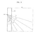
- FIG. 8 is an exemplary diagram illustrating a second region of interest (ROI) and a plurality of angles and lines for calculating an angle at which a needle is introduced according to an exemplary embodiment of the present invention.
- ROI region of interest
- FIG. 9 is an exemplary diagram illustrating a guide line of a needle according to an exemplary embodiment of the present invention.
- FIG. 1 is a block diagram showing a configuration of an ultrasound system 100 according to an exemplary diagram of the present invention.
- the ultrasound system 100 according to the present embodiment includes an ultrasound data acquisition unit 110, a processor 120, a storage unit 130, and a display unit 140.
- the ultrasound system 100 further includes a medical tool (not shown) that is inserted into a living body to remove a lesion within the living body.
- the medical tool may include a needle, but is not limited thereto.
- the ultrasound data acquisition unit 110 is configured to transmit an ultrasound signal to a living body, receive an ultrasound echo signal reflected from the living body, and acquire ultrasound data corresponding to an ultrasound image.
- the living body includes an object such as a lesion, the heart, or the liver.
- FIG. 2 is a block diagram showing a configuration of the ultrasound data acquisition unit 110 in the ultrasound system of FIG. 1 , according to an exemplary diagram of the present invention.
- the ultrasound data acquisition unit 110 includes an ultrasound probe 210, a transmitter 220, a receiver 230, and an ultrasound data forming section 240.
- the ultrasound probe 210 includes a plurality of transducer elements (not shown) that convert electrical signals into ultrasound signals, and vice versa.
- the ultrasound probe 210 is configured to transmit an ultrasound signal to a living body and receive an ultrasound echo signal reflected from the living body to generate an electrical signal (hereinafter, referred to as a "reception signal").
- the reception signal is an analog signal.
- the ultrasound probe 210 includes a linear probe, a convex probe, and a three-dimensional (3D) probe.
- the transmitter 220 controls the transmission of an ultrasound signal.
- the transmitter 220 also produces an electrical signal (hereinafter, referred to as a "transmission signal") that is used to obtain an ultrasound image in consideration of the transducer elements and a focal point.
- the transmitter 220 sequentially creates a transmission signal that is used to obtain each of a plurality of ultrasound images UI N (N ⁇ 1).
- the ultrasound probe 210 converts the transmission signal sequentially received from the transmitter 220 into an ultrasound signal, transmits the ultrasound signal to a living body, and receives an ultrasound echo signal reflected from the living body to create a reception signal.
- the receiver 230 performs analog-to-digital conversion on the reception signal provided by the ultrasound probe 210 to produce a digital signal.
- the receiver 230 also performs reception beamforming on the digital signal in consideration of the transducer elements and a focal point to create a focused reception signal. Since the reception beamforming may be performed by using various known methods, a detailed description thereof is omitted here.
- the receiver 230 performs analog-to-digital conversion on the reception signal sequentially received from the ultrasound probe 210 to produce a digital signal and performs reception beamforming on the digital signal in consideration of the transducer elements and a focal point to create a focused reception signal.
- the ultrasound data forming section 240 creates ultrasound data corresponding to an ultrasound image by using the focused reception signal provided by the receiver 230.
- the ultrasound data includes radio frequency (RF) data.
- RF radio frequency
- the ultrasound data forming section 240 generates ultrasound data corresponding to each of the plurality of ultrasound images UI N (N ⁇ 1) by using the focused reception signal sequentially received from the receiver 230.
- the ultrasound data forming section 240 may also perform various signal processings, such as gain control, needed to form ultrasound data, on the focused reception signal.
- the processor 120 is connected to the ultrasound data acquisition unit 110.
- the processor 120 includes a central processing unit (CPU), a microprocessor, and a graphics processing unit (GPU).
- CPU central processing unit
- microprocessor microprocessor
- GPU graphics processing unit
- FIG. 4 is a flowchart of a process of setting a guide line of a medical tool, i.e., a needle, according to an exemplary embodiment of the present invention.
- the processor 120 produces an ultrasound image by using ultrasound data provided by the ultrasound data acquisition unit 110 (S402).
- the processor 120 creates a plurality of ultrasound images UI N (N ⁇ 1) by using ultrasound data sequentially received from the ultrasound data acquisition unit 110.
- the processor 120 performs downsampling on the plurality of ultrasound images UI k (1 ⁇ k ⁇ N) in order to reduce processing time and storage space thereof and creates a plurality of ultrasound images CUI k (1 ⁇ k ⁇ N) (hereinafter called "copies of ultrasound images") (S404). Since the downsampling is performed by using various known methods, a detailed description thereof is omitted here.
- the processor 120 generates a needle movement image by using a predetermined number of copies of ultrasound images among the plurality of copies of ultrasound images (S406).
- the processor 120 selects a predetermined number (e.g., five) of copies CUI i-2 , CUI i-1 , CUI i , CUI i+1 , and CUI i+2 of ultrasound images in a temporal direction with respect to an i-th copy CUI i of ultrasound image.
- the processor 120 generates a needle movement image by using the selected copies CUI i-2 , CUI i-i , CUI i , CUI i+1 , and CUI i+2 of ultrasound images.
- the processor 120 creates a mask image by using an ultrasound image UI i and the needle movement image NMI i (S408).
- the mask image is an image for emphasizing a needle in the ultrasound image UI i .
- the processor 120 detects a position at which the needle is introduced (inserted) by using the mask image (S410).
- the processor 120 sets a region of interest (ROI) having a preset size on the mask image MI i in consideration of a direction in which the needle is introduced.
- the direction in which the needle is introduced may be manually set by the user, or automatically set by a system.
- the processor 120 sets an ROI having a size corresponding to one fifth of a width W of the mask image MI i from the leftmost side, in consideration of the direction in which the needle is introduced from the left side into the right side. As shown in FIG.
- the processor 120 accumulates brightness values of pixels within the ROI for each depth of the mask image MI i along a width direction of the mask image MI i and calculates first cumulative brightness (intensity) values.
- the processor 120 detects a maximum cumulative brightness value among the calculated first cumulative brightness values and a depth corresponding to the maximum cumulative brightness value as a position NIP at which the needle is introduced.
- the processor 120 sets a plurality of angles ⁇ i (1 ⁇ i ⁇ N) based on the position NIP at which the needle is introduced, and sets a plurality of lines L i (1 ⁇ i ⁇ N) corresponding to the plurality of angles ⁇ i from the position NIP, respectively, on a mask image MI i .
- the processor 120 then calculates third cumulative brightness values of pixels corresponding to the plurality of lines L i (1 ⁇ i ⁇ N).
- the processor 120 detects a maximum cumulative brightness value among the third calculated cumulative brightness values and an angle corresponding to the maximum cumulative brightness value as an angle at which the needle is introduced.
- the processor 120 sets a needle guide line LGL on the ultrasound image UI i based on the detected position and angle at which the needle is introduced (S414).
- the needle movement image may be produced by using the ultrasound image without performing the downsampling.
- the storage unit 130 stores ultrasound data acquired by the ultrasound data acquisition unit 110 as well as ultrasound images (original ultrasound images and copies of ultrasound images) generated by the processor 120.
- the storage unit 130 also stores a position and an angle at which a needle is introduced, which are detected by the processor 120.
- the display unit 140 displays ultrasound images (original ultrasound images and/or copies of ultrasound images) generated by the processor 120, as well as a needle guide line set on an ultrasound image.
Landscapes
- Health & Medical Sciences (AREA)
- Life Sciences & Earth Sciences (AREA)
- Engineering & Computer Science (AREA)
- Physics & Mathematics (AREA)
- Surgery (AREA)
- Heart & Thoracic Surgery (AREA)
- Public Health (AREA)
- Veterinary Medicine (AREA)
- General Health & Medical Sciences (AREA)
- Animal Behavior & Ethology (AREA)
- Molecular Biology (AREA)
- Biomedical Technology (AREA)
- Medical Informatics (AREA)
- Pathology (AREA)
- Computer Vision & Pattern Recognition (AREA)
- Nuclear Medicine, Radiotherapy & Molecular Imaging (AREA)
- Radiology & Medical Imaging (AREA)
- Biophysics (AREA)
- General Physics & Mathematics (AREA)
- Theoretical Computer Science (AREA)
- Ultra Sonic Daignosis Equipment (AREA)
- Plasma & Fusion (AREA)
- Otolaryngology (AREA)
- Physiology (AREA)
Abstract
Description
- This application claims the benefit of Korean Patent Application No.
10-2012-0125597, filed on November 7, 2012 - One or more embodiments of the present invention relate to an ultrasound system, and more particularly, to an ultrasound system and method for providing a guide line corresponding to an introduction pathway, i.e., a pathway through which a needle is inserted.
- With the advancement in medical technologies, a technique for treating or examining a living body without direct incision is being used. The technique involves cutting a hole to a minimum size and inserting a medical needle such as an ablator or a biopsy needle into a living tissue having a lesion while observing images of the inside of the living body. This method is called "image-guided surgery" or "interventional surgical procedure" because it is performed by observing the inside of a living body using a medical imaging technique such as computerized tomography (CT) or magnetic resonance imaging (MRI). That is, the interventional surgical procedure is a technique for treatment or diagnosis whereby a medical needle is inserted directly through the skin into a lesion to be examined or treated while viewing images obtained from CT or MRI during surgery. The interventional surgical procedure usually does not require general anesthesia, involves reduced physical burden of a living body and little pain or torture, requires a short hospital stay, and has short recovery times after surgery. Thus, this procedure is less costly and more effective than a surgical treatment requiring incision.
- However, when an interventional surgical procedure is performed by using CT or MR, it is difficult to obtain an image of a living body in real time. Furthermore, use of CT during surgery may pose a risk of long term radiation exposure to both a surgeon and a living body. On the other hand, use of an ultrasound system during an interventional surgical procedure may not only provide real-time ultrasound images but also pose little harm to a living body.
- One or more embodiments of the present invention include an ultrasound system and method for setting a guide line indicating a pathway through which a needle is inserted on an ultrasound image, based on a position and an angle at which the needle is introduced, which are detected by using the ultrasound image.
- Additional aspects will be set forth in part in the description which follows and, in part, will be apparent from the description, or may be learned by practice of the presented embodiments.
- According to one or more embodiments of the present invention, an ultrasound system includes an ultrasound data acquisition unit that transmits an ultrasound signal to a living body into which the needle is inserted, receives an ultrasound echo signal reflected from the living body, and acquires ultrasound data corresponding to each of a plurality of ultrasound images, and a processor that generates the plurality of ultrasound images by using the ultrasound data, creates a mask image for detecting a position and an angle at which the needle is introduced, detects the position and angle by using the mask image, and sets a guide line of the needle on the ultrasound image by using the position and angle.
- The ultrasound system and method according to the embodiments of the present invention may provide a guide line corresponding to a pathway through which a needle is inserted (i.e., a direction in which the needle travels) without using additional devices such as a needle kit and a sensor.
- These and/or other aspects will become apparent and more readily appreciated from the following description of the embodiments, taken in conjunction with the accompanying drawings in which:
-
FIG. 1 is a block diagram showing a configuration of an ultrasound system according to an exemplary embodiment of the present invention; -
FIG. 2 is a block diagram showing a configuration of an ultrasound data acquisition unit in the ultrasound system ofFIG. 1 , according to an exemplary diagram of the present invention; -
FIG. 3 is an exemplary diagram illustrating a plurality of ultrasound images; -
FIG. 4 is a flowchart of a process of setting a guide line of a needle according to an exemplary embodiment of the present invention; -
FIG. 5 is an exemplary diagram illustrating a mask image and a first region of interest (ROI) according to an exemplary embodiment of the present invention; -
FIG. 6 is an exemplary diagram illustrating first cumulative brightness values and needle introduction positions with respect to a depth according to an exemplary embodiment of the present invention; -
FIG. 7 is an exemplary diagram illustrating a first mean value, a second mean value, a start point, an end position, and a length between the start point and the end point that are needed for calculating an angle at which a needle is introduced according to an exemplary embodiment of the present invention; -
FIG. 8 is an exemplary diagram illustrating a second region of interest (ROI) and a plurality of angles and lines for calculating an angle at which a needle is introduced according to an exemplary embodiment of the present invention; and -
FIG. 9 is an exemplary diagram illustrating a guide line of a needle according to an exemplary embodiment of the present invention. - Reference will now be made in detail to embodiments, examples of which are illustrated in the accompanying drawings, wherein like reference numerals refer to like elements throughout. As used herein, the term "and/or" includes any and all combinations of one or more of the associated listed items. Expressions such as "at least one of," when preceding a list of elements, modify the entire list of elements and do not modify the individual elements of the list.
-
FIG. 1 is a block diagram showing a configuration of anultrasound system 100 according to an exemplary diagram of the present invention. Referring toFIG. 1 , theultrasound system 100 according to the present embodiment includes an ultrasounddata acquisition unit 110, aprocessor 120, astorage unit 130, and adisplay unit 140. Theultrasound system 100 further includes a medical tool (not shown) that is inserted into a living body to remove a lesion within the living body. In the present embodiment, the medical tool may include a needle, but is not limited thereto. - The ultrasound
data acquisition unit 110 is configured to transmit an ultrasound signal to a living body, receive an ultrasound echo signal reflected from the living body, and acquire ultrasound data corresponding to an ultrasound image. The living body includes an object such as a lesion, the heart, or the liver. -
FIG. 2 is a block diagram showing a configuration of the ultrasounddata acquisition unit 110 in the ultrasound system ofFIG. 1 , according to an exemplary diagram of the present invention. Referring toFIG. 2 , the ultrasounddata acquisition unit 110 includes anultrasound probe 210, atransmitter 220, areceiver 230, and an ultrasounddata forming section 240. - The
ultrasound probe 210 includes a plurality of transducer elements (not shown) that convert electrical signals into ultrasound signals, and vice versa. Theultrasound probe 210 is configured to transmit an ultrasound signal to a living body and receive an ultrasound echo signal reflected from the living body to generate an electrical signal (hereinafter, referred to as a "reception signal"). The reception signal is an analog signal. Theultrasound probe 210 includes a linear probe, a convex probe, and a three-dimensional (3D) probe. - The
transmitter 220 controls the transmission of an ultrasound signal. Thetransmitter 220 also produces an electrical signal (hereinafter, referred to as a "transmission signal") that is used to obtain an ultrasound image in consideration of the transducer elements and a focal point. In the present embodiment, as shown inFIG. 3 , thetransmitter 220 sequentially creates a transmission signal that is used to obtain each of a plurality of ultrasound images UIN (N≥1). Thus, theultrasound probe 210 converts the transmission signal sequentially received from thetransmitter 220 into an ultrasound signal, transmits the ultrasound signal to a living body, and receives an ultrasound echo signal reflected from the living body to create a reception signal. - The
receiver 230 performs analog-to-digital conversion on the reception signal provided by theultrasound probe 210 to produce a digital signal. Thereceiver 230 also performs reception beamforming on the digital signal in consideration of the transducer elements and a focal point to create a focused reception signal. Since the reception beamforming may be performed by using various known methods, a detailed description thereof is omitted here. In the present embodiment, thereceiver 230 performs analog-to-digital conversion on the reception signal sequentially received from theultrasound probe 210 to produce a digital signal and performs reception beamforming on the digital signal in consideration of the transducer elements and a focal point to create a focused reception signal. - The ultrasound
data forming section 240 creates ultrasound data corresponding to an ultrasound image by using the focused reception signal provided by thereceiver 230. The ultrasound data includes radio frequency (RF) data. In the present embodiment, the ultrasounddata forming section 240 generates ultrasound data corresponding to each of the plurality of ultrasound images UIN (N≥1) by using the focused reception signal sequentially received from thereceiver 230. The ultrasounddata forming section 240 may also perform various signal processings, such as gain control, needed to form ultrasound data, on the focused reception signal. - Referring back to
FIG. 1 , theprocessor 120 is connected to the ultrasounddata acquisition unit 110. Theprocessor 120 includes a central processing unit (CPU), a microprocessor, and a graphics processing unit (GPU). -
FIG. 4 is a flowchart of a process of setting a guide line of a medical tool, i.e., a needle, according to an exemplary embodiment of the present invention. Referring toFIG. 4 , theprocessor 120 produces an ultrasound image by using ultrasound data provided by the ultrasound data acquisition unit 110 (S402). In the present embodiment, theprocessor 120 creates a plurality of ultrasound images UIN (N≥1) by using ultrasound data sequentially received from the ultrasounddata acquisition unit 110. - The
processor 120 performs downsampling on the plurality of ultrasound images UIk (1≤k≤N) in order to reduce processing time and storage space thereof and creates a plurality of ultrasound images CUIk (1≤k≤N) (hereinafter called "copies of ultrasound images") (S404). Since the downsampling is performed by using various known methods, a detailed description thereof is omitted here. - The
processor 120 generates a needle movement image by using a predetermined number of copies of ultrasound images among the plurality of copies of ultrasound images (S406). In the present embodiment, theprocessor 120 selects a predetermined number (e.g., five) of copies CUIi-2, CUIi-1, CUIi, CUIi+1, and CUIi+2 of ultrasound images in a temporal direction with respect to an i-th copy CUIi of ultrasound image. Theprocessor 120 generates a needle movement image by using the selected copies CUIi-2, CUIi-i, CUIi, CUIi+1, and CUIi+2 of ultrasound images. For example, theprocessor 120 creates a needle movement image NMIi by using Equation (1) below:
- The
processor 120 creates a mask image by using an ultrasound image UIi and the needle movement image NMIi (S408). The mask image is an image for emphasizing a needle in the ultrasound image UIi. In the present embodiment, theprocessor 120 may create a mask image MIi by using Equation (2) below:
- The
processor 120 detects a position at which the needle is introduced (inserted) by using the mask image (S410). In the present embodiment, theprocessor 120 sets a region of interest (ROI) having a preset size on the mask image MIi in consideration of a direction in which the needle is introduced. In this case, the direction in which the needle is introduced may be manually set by the user, or automatically set by a system. For example, as shown inFIG. 5 , theprocessor 120 sets an ROI having a size corresponding to one fifth of a width W of the mask image MIi from the leftmost side, in consideration of the direction in which the needle is introduced from the left side into the right side. As shown inFIG. 6 , theprocessor 120 accumulates brightness values of pixels within the ROI for each depth of the mask image MIi along a width direction of the mask image MIi and calculates first cumulative brightness (intensity) values. Theprocessor 120 detects a maximum cumulative brightness value among the calculated first cumulative brightness values and a depth corresponding to the maximum cumulative brightness value as a position NIP at which the needle is introduced. - The
processor 120 calculates an angle at which the needle is introduced (inserted) based on the position NIP at which the needle is introduced (S412). In one embodiment, as shown inFIG. 7 , theprocessor 120 calculates a first mean value M1 of the first cumulative brightness values and a second mean value M2 of second cumulative brightness values obtained by subtracting the first mean value M1 from each of the first cumulative brightness values._ Theprocessor 120 then detects intersection points of the second mean value M2 and the first cumulative brightness values as a start point nStart and an end point nEnd. Theprocessor 120 calculates an angle at which the needle is introduced based on a length nNDLength from the start point nStart to the end point nEnd. For example, theprocessor 120 may calculate an angle θ at which the needle is introduced by using Equation (3) below:
- In another embodiment, as shown in
FIG. 8 , theprocessor 120 sets a plurality of angles Θi (1≤i≤N) based on the position NIP at which the needle is introduced, and sets a plurality of lines Li (1≤i≤N) corresponding to the plurality of angles Θi from the position NIP, respectively, on a mask image MIi. Theprocessor 120 then calculates third cumulative brightness values of pixels corresponding to the plurality of lines Li (1≤i≤N). Theprocessor 120 detects a maximum cumulative brightness value among the third calculated cumulative brightness values and an angle corresponding to the maximum cumulative brightness value as an angle at which the needle is introduced. - Next, as shown in
FIG. 9 , theprocessor 120 sets a needle guide line LGL on the ultrasound image UIi based on the detected position and angle at which the needle is introduced (S414). - While the ultrasound image is downsampled and a needle movement image is created by using the downsampled image, the needle movement image may be produced by using the ultrasound image without performing the downsampling.
- Referring back to
FIG. 1 , thestorage unit 130 stores ultrasound data acquired by the ultrasounddata acquisition unit 110 as well as ultrasound images (original ultrasound images and copies of ultrasound images) generated by theprocessor 120. Thestorage unit 130 also stores a position and an angle at which a needle is introduced, which are detected by theprocessor 120. - The
display unit 140 displays ultrasound images (original ultrasound images and/or copies of ultrasound images) generated by theprocessor 120, as well as a needle guide line set on an ultrasound image. - While one or more embodiments of the present invention have been described with reference to the figures, it will be understood by those of ordinary skill in the art that various changes in form and details may be made therein without departing from the spirit and scope of the present invention as defined by the following claims.
Claims (15)
- An ultrasound system comprising
an ultrasound data acquisition unit that transmits an ultrasound signal to a living body into which the needle is inserted, receives an ultrasound echo signal reflected from the living body, and acquires ultrasound data corresponding to each of a plurality of ultrasound images and
a processor that generates the plurality of ultrasound images by using the ultrasound data, creates a mask image for detecting a position and an angle at which the needle is introduced, detects the position and angle by using the mask image, and sets a guide line of the needle on the ultrasound image by using the position and angle. - The ultrasound system of claim 1, wherein the processor performs downsampling on each of the plurality of ultrasound images to create a plurality of copies of ultrasound images.
- The ultrasound system of claim 2, wherein the processor creates a needle movement image by using a predetermined number of copies of ultrasound images among the plurality of copies of ultrasound images
- The ultrasound system of claim 3, wherein the processor selects a predetermined number of copies of ultrasound images in a temporal direction with respect to each of the plurality of copies of ultrasound images and generates the needle movement image by using the selected copies of ultrasound images.
- The ultrasound system of claim 4, wherein the processor generates the image of movement of the needle by using

- The ultrasound system of claim 3, wherein the processor creates the mask image for emphasizing the needle in the ultrasound image by using the ultrasound image and the needle movement image.
- The ultrasound system of claim 6, wherein the processor creates the mask image by using MI=UI×α+NMI×(1-α) where MI is the mask image, UI is the ultrasound image, and α is a weighting factor.
- The ultrasound system of claim 6, wherein the processor sets a region of interest (ROI) having a preset size on the mask image in consideration of a direction in which the needle is introduced, accumulates brightness values of pixels within the ROI for each depth of the mask image along a width direction of the mask image to thereby calculate first cumulative brightness values, detects a maximum cumulative brightness value among the calculated first cumulative brightness values, and detects a depth corresponding to the maximum cumulative brightness value as a position at which the needle is introduced.
- The ultrasound system of claim 8, wherein the processor calculates the angle at which the needle is introduced based on the position at which the needle is introduced.
- The ultrasound system of claim 9, wherein the processor calculates a first mean value of the first cumulative brightness values and a second mean value of second cumulative brightness values that are obtained by subtracting the first mean value from each of the first cumulative brightness values, detects a start point and an end point based on the first cumulative brightness values and the second mean value, calculates a length between the start point and the end point, and calculates the angle at which the needle is introduced based on the length.
- The ultrasound system of claim 9, wherein the processor sets a plurality of angles based on the position at which the needle is introduced, sets a plurality of lines corresponding to the plurality of angles Θi from the position, respectively, on the mask image, calculates third cumulative brightness values of pixels in the plurality of lines, detects a maximum cumulative brightness value among the third cumulative brightness values, and detects an angle corresponding to the maximum cumulative brightness value as the angle at which the needle is introduced.
- A method of providing a guide line of a needle, the method comprising:transmitting an ultrasound signal to a living body into which the needle is inserted, receiving an ultrasound echo signal reflected from the living body, and acquiring ultrasound data corresponding to each of a plurality of ultrasound images,generating the plurality of ultrasound images by using the ultrasound data;creating a mask image for detecting a position and an angle at which the needle is introduced by using the plurality of ultrasound images;detecting the position and angle by using the mask image; andsetting a guide line of the needle on the ultrasound image by using the position and angle.
- The method of claim 12, wherein the creating of the mask image comprises performing downsampling on each of the plurality of ultrasound images to create a plurality of copies of ultrasound images.
- The method of claim 13, wherein the creating of the mask image comprises generating a needle movement image by using a predetermined number of copies of ultrasound images among the plurality of copies of ultrasound images.
- The method of claim 14, wherein the creating of the mask image comprises creating the mask image for emphasizing the needle in the ultrasound image by using the ultrasound image and the needle movement image.
Applications Claiming Priority (1)
| Application Number | Priority Date | Filing Date | Title |
|---|---|---|---|
| KR20120125597A KR101478623B1 (en) | 2012-11-07 | 2012-11-07 | Ultrasound system and method for providing guide line of needle |
Publications (2)
| Publication Number | Publication Date |
|---|---|
| EP2730229A1 true EP2730229A1 (en) | 2014-05-14 |
| EP2730229B1 EP2730229B1 (en) | 2022-05-25 |
Family
ID=49518800
Family Applications (1)
| Application Number | Title | Priority Date | Filing Date |
|---|---|---|---|
| EP13191520.9A Active EP2730229B1 (en) | 2012-11-07 | 2013-11-05 | Ultrasound system and method for providing guide line of needle |
Country Status (3)
| Country | Link |
|---|---|
| US (1) | US9706978B2 (en) |
| EP (1) | EP2730229B1 (en) |
| KR (1) | KR101478623B1 (en) |
Cited By (2)
| Publication number | Priority date | Publication date | Assignee | Title |
|---|---|---|---|---|
| CN105581813A (en) * | 2015-12-22 | 2016-05-18 | 汕头市超声仪器研究所有限公司 | Full-automatic puncture needle developing enhancing method based on encoder |
| CN105596030A (en) * | 2015-12-22 | 2016-05-25 | 汕头市超声仪器研究所有限公司 | Full-automatic puncture needle developing enhancing method based on pattern recognition |
Families Citing this family (10)
| Publication number | Priority date | Publication date | Assignee | Title |
|---|---|---|---|---|
| KR101478623B1 (en) * | 2012-11-07 | 2015-01-02 | 삼성메디슨 주식회사 | Ultrasound system and method for providing guide line of needle |
| JP6447071B2 (en) * | 2013-12-11 | 2019-01-09 | コニカミノルタ株式会社 | Ultrasonic diagnostic apparatus, ultrasonic image processing method, and program |
| US10893846B2 (en) * | 2015-01-09 | 2021-01-19 | Konica Minolta, Inc. | Ultrasound diagnosis apparatus |
| JP6346987B2 (en) * | 2015-03-10 | 2018-06-20 | 富士フイルム株式会社 | Acoustic wave image generation apparatus and control method thereof |
| JP6705134B2 (en) * | 2015-08-21 | 2020-06-03 | コニカミノルタ株式会社 | Ultrasonic image diagnostic apparatus, ultrasonic image processing method, and ultrasonic image processing program |
| US11007382B2 (en) * | 2016-06-29 | 2021-05-18 | Koninklijke Philips N.V. | Real time dosimetry of ultrasound imaging probe |
| US10102452B2 (en) | 2017-03-14 | 2018-10-16 | Clarius Mobile Health Corp. | Systems and methods for identifying an imaged needle in an ultrasound image |
| KR102572015B1 (en) * | 2018-02-08 | 2023-08-29 | 지멘스 메디컬 솔루션즈 유에스에이, 인크. | Ultrasound system and method for providing insertion position of read instrument |
| KR102747176B1 (en) | 2018-12-11 | 2024-12-27 | 삼성메디슨 주식회사 | Ultrasound imaging apparatus, method for controlling the same, and computer program product |
| KR102573286B1 (en) * | 2021-04-02 | 2023-08-30 | 연세대학교 산학협력단 | Path forming device for bone screw |
Citations (4)
| Publication number | Priority date | Publication date | Assignee | Title |
|---|---|---|---|---|
| US20090093717A1 (en) * | 2007-10-04 | 2009-04-09 | Siemens Corporate Research, Inc. | Automated Fetal Measurement From Three-Dimensional Ultrasound Data |
| US20110201931A1 (en) * | 2010-02-16 | 2011-08-18 | Palmeri Mark L | Ultrasound Methods, Systems and Computer Program Products for Imaging Contrasting Objects Using Combined Images |
| US20110249878A1 (en) * | 2010-04-07 | 2011-10-13 | Sonosite, Inc. | Systems and methods for enhanced imaging of objects within an image |
| US20120253181A1 (en) * | 2011-04-01 | 2012-10-04 | Toshiba Medical Systems Corporation | Ultrasound diagnosis apparatus and controlling method |
Family Cites Families (13)
| Publication number | Priority date | Publication date | Assignee | Title |
|---|---|---|---|---|
| WO1997003609A1 (en) | 1995-07-16 | 1997-02-06 | Ultra-Guide Ltd. | Free-hand aiming of a needle guide |
| JP4307626B2 (en) * | 1999-05-07 | 2009-08-05 | オリンパス株式会社 | Ultrasonic diagnostic equipment |
| US6524247B2 (en) | 2001-05-15 | 2003-02-25 | U-Systems, Inc. | Method and system for ultrasound imaging of a biopsy needle |
| US6733458B1 (en) * | 2001-09-25 | 2004-05-11 | Acuson Corporation | Diagnostic medical ultrasound systems and methods using image based freehand needle guidance |
| JP4381344B2 (en) | 2005-05-17 | 2009-12-09 | ジーイー・メディカル・システムズ・グローバル・テクノロジー・カンパニー・エルエルシー | Ultrasonic diagnostic equipment |
| EP2363071A1 (en) * | 2010-03-03 | 2011-09-07 | Technische Universiteit Eindhoven | Needle detection in medical image data |
| ES2778041T3 (en) * | 2010-05-28 | 2020-08-07 | Bard Inc C R | Apparatus for use with needle insertion guidance system |
| US9226729B2 (en) * | 2010-09-28 | 2016-01-05 | Fujifilm Corporation | Ultrasound diagnostic system, ultrasound image generation apparatus, and ultrasound image generation method |
| KR101478623B1 (en) * | 2012-11-07 | 2015-01-02 | 삼성메디슨 주식회사 | Ultrasound system and method for providing guide line of needle |
| KR20140066584A (en) * | 2012-11-23 | 2014-06-02 | 삼성메디슨 주식회사 | Ultrasound system and method for providing guide line of needle |
| US9642592B2 (en) * | 2013-01-03 | 2017-05-09 | Siemens Medical Solutions Usa, Inc. | Needle enhancement in diagnostic ultrasound imaging |
| JP6447071B2 (en) * | 2013-12-11 | 2019-01-09 | コニカミノルタ株式会社 | Ultrasonic diagnostic apparatus, ultrasonic image processing method, and program |
| JP6405712B2 (en) * | 2014-05-30 | 2018-10-17 | コニカミノルタ株式会社 | Ultrasonic diagnostic equipment |
-
2012
- 2012-11-07 KR KR20120125597A patent/KR101478623B1/en active Active
-
2013
- 2013-11-05 EP EP13191520.9A patent/EP2730229B1/en active Active
- 2013-11-06 US US14/073,331 patent/US9706978B2/en active Active
Patent Citations (4)
| Publication number | Priority date | Publication date | Assignee | Title |
|---|---|---|---|---|
| US20090093717A1 (en) * | 2007-10-04 | 2009-04-09 | Siemens Corporate Research, Inc. | Automated Fetal Measurement From Three-Dimensional Ultrasound Data |
| US20110201931A1 (en) * | 2010-02-16 | 2011-08-18 | Palmeri Mark L | Ultrasound Methods, Systems and Computer Program Products for Imaging Contrasting Objects Using Combined Images |
| US20110249878A1 (en) * | 2010-04-07 | 2011-10-13 | Sonosite, Inc. | Systems and methods for enhanced imaging of objects within an image |
| US20120253181A1 (en) * | 2011-04-01 | 2012-10-04 | Toshiba Medical Systems Corporation | Ultrasound diagnosis apparatus and controlling method |
Cited By (2)
| Publication number | Priority date | Publication date | Assignee | Title |
|---|---|---|---|---|
| CN105581813A (en) * | 2015-12-22 | 2016-05-18 | 汕头市超声仪器研究所有限公司 | Full-automatic puncture needle developing enhancing method based on encoder |
| CN105596030A (en) * | 2015-12-22 | 2016-05-25 | 汕头市超声仪器研究所有限公司 | Full-automatic puncture needle developing enhancing method based on pattern recognition |
Also Published As
| Publication number | Publication date |
|---|---|
| EP2730229B1 (en) | 2022-05-25 |
| US20140128728A1 (en) | 2014-05-08 |
| US9706978B2 (en) | 2017-07-18 |
| KR20140059023A (en) | 2014-05-15 |
| KR101478623B1 (en) | 2015-01-02 |
Similar Documents
| Publication | Publication Date | Title |
|---|---|---|
| US9706978B2 (en) | Ultrasound system and method for providing guide line of needle | |
| US9437036B2 (en) | Medical system, medical imaging apparatus, and method of providing three-dimensional marker | |
| JP5495593B2 (en) | Ultrasonic diagnostic apparatus and puncture support control program | |
| US7774045B2 (en) | Medical guiding system, medical guiding program, and medical guiding method | |
| US9173632B2 (en) | Ultrasonic diagnosis system and image data display control program | |
| US20170095226A1 (en) | Ultrasonic diagnostic apparatus and medical image diagnostic apparatus | |
| US20070167762A1 (en) | Ultrasound system for interventional treatment | |
| US20140039316A1 (en) | Ultrasonic diagnostic apparatus and ultrasonic image processing method | |
| EP2735271A1 (en) | Ultrasound system and method for providing guideline of needle | |
| KR102278893B1 (en) | Medical image processing apparatus and medical image registration method using the same | |
| EP2732769B1 (en) | Method and apparatus for displaying medical image | |
| JP5404066B2 (en) | Medical image display system | |
| JP4205957B2 (en) | Ultrasonic diagnostic equipment | |
| US8663110B2 (en) | Providing an optimal ultrasound image for interventional treatment in a medical system | |
| EP2644102A1 (en) | Method and apparatus for indicating medical equipment on ultrasound image | |
| CN100473355C (en) | System for introducing a medical instrument into a patient | |
| KR101242298B1 (en) | Ultrasound system and method for storing ultrasound images | |
| KR101143663B1 (en) | Medical system and methdo for providing optimal ultrasound image for interventional treatment | |
| EP2740409B1 (en) | Medical system of providing three-dimensional marker | |
| KR102035991B1 (en) | Method and ultrasound system for generating image of target object | |
| JP5675930B2 (en) | X-ray diagnostic equipment | |
| EP2454996A1 (en) | Providing an optimal ultrasound image for interventional treatment in a medical system | |
| JP7359414B2 (en) | medical imaging equipment | |
| JP2006149482A (en) | Ultrasonic diagnostic equipment | |
| JP2014057883A (en) | Ultrasonic diagnostic apparatus and puncture supporting control program |
Legal Events
| Date | Code | Title | Description |
|---|---|---|---|
| PUAI | Public reference made under article 153(3) epc to a published international application that has entered the european phase |
Free format text: ORIGINAL CODE: 0009012 |
|
| 17P | Request for examination filed |
Effective date: 20131105 |
|
| AK | Designated contracting states |
Kind code of ref document: A1 Designated state(s): AL AT BE BG CH CY CZ DE DK EE ES FI FR GB GR HR HU IE IS IT LI LT LU LV MC MK MT NL NO PL PT RO RS SE SI SK SM TR |
|
| AX | Request for extension of the european patent |
Extension state: BA ME |
|
| R17P | Request for examination filed (corrected) |
Effective date: 20141111 |
|
| RBV | Designated contracting states (corrected) |
Designated state(s): AL AT BE BG CH CY CZ DE DK EE ES FI FR GB GR HR HU IE IS IT LI LT LU LV MC MK MT NL NO PL PT RO RS SE SI SK SM TR |
|
| STAA | Information on the status of an ep patent application or granted ep patent |
Free format text: STATUS: EXAMINATION IS IN PROGRESS |
|
| 17Q | First examination report despatched |
Effective date: 20190102 |
|
| REG | Reference to a national code |
Ref country code: DE Ref legal event code: R079 Ref document number: 602013081727 Country of ref document: DE Free format text: PREVIOUS MAIN CLASS: A61B0008080000 Ipc: A61B0008000000 |
|
| GRAP | Despatch of communication of intention to grant a patent |
Free format text: ORIGINAL CODE: EPIDOSNIGR1 |
|
| STAA | Information on the status of an ep patent application or granted ep patent |
Free format text: STATUS: GRANT OF PATENT IS INTENDED |
|
| RIC1 | Information provided on ipc code assigned before grant |
Ipc: G06T 7/11 20170101ALI20220105BHEP Ipc: G06T 7/73 20170101ALI20220105BHEP Ipc: A61B 10/02 20060101ALI20220105BHEP Ipc: A61B 8/08 20060101ALI20220105BHEP Ipc: G06T 7/00 20170101ALI20220105BHEP Ipc: A61B 8/00 20060101AFI20220105BHEP |
|
| INTG | Intention to grant announced |
Effective date: 20220120 |
|
| GRAS | Grant fee paid |
Free format text: ORIGINAL CODE: EPIDOSNIGR3 |
|
| GRAA | (expected) grant |
Free format text: ORIGINAL CODE: 0009210 |
|
| STAA | Information on the status of an ep patent application or granted ep patent |
Free format text: STATUS: THE PATENT HAS BEEN GRANTED |
|
| AK | Designated contracting states |
Kind code of ref document: B1 Designated state(s): AL AT BE BG CH CY CZ DE DK EE ES FI FR GB GR HR HU IE IS IT LI LT LU LV MC MK MT NL NO PL PT RO RS SE SI SK SM TR |
|
| REG | Reference to a national code |
Ref country code: GB Ref legal event code: FG4D |
|
| REG | Reference to a national code |
Ref country code: CH Ref legal event code: EP |
|
| REG | Reference to a national code |
Ref country code: DE Ref legal event code: R096 Ref document number: 602013081727 Country of ref document: DE |
|
| REG | Reference to a national code |
Ref country code: AT Ref legal event code: REF Ref document number: 1493937 Country of ref document: AT Kind code of ref document: T Effective date: 20220615 |
|
| REG | Reference to a national code |
Ref country code: IE Ref legal event code: FG4D |
|
| REG | Reference to a national code |
Ref country code: LT Ref legal event code: MG9D |
|
| REG | Reference to a national code |
Ref country code: NL Ref legal event code: MP Effective date: 20220525 |
|
| REG | Reference to a national code |
Ref country code: AT Ref legal event code: MK05 Ref document number: 1493937 Country of ref document: AT Kind code of ref document: T Effective date: 20220525 |
|
| PG25 | Lapsed in a contracting state [announced via postgrant information from national office to epo] |
Ref country code: SE Free format text: LAPSE BECAUSE OF FAILURE TO SUBMIT A TRANSLATION OF THE DESCRIPTION OR TO PAY THE FEE WITHIN THE PRESCRIBED TIME-LIMIT Effective date: 20220525 Ref country code: PT Free format text: LAPSE BECAUSE OF FAILURE TO SUBMIT A TRANSLATION OF THE DESCRIPTION OR TO PAY THE FEE WITHIN THE PRESCRIBED TIME-LIMIT Effective date: 20220926 Ref country code: NO Free format text: LAPSE BECAUSE OF FAILURE TO SUBMIT A TRANSLATION OF THE DESCRIPTION OR TO PAY THE FEE WITHIN THE PRESCRIBED TIME-LIMIT Effective date: 20220825 Ref country code: NL Free format text: LAPSE BECAUSE OF FAILURE TO SUBMIT A TRANSLATION OF THE DESCRIPTION OR TO PAY THE FEE WITHIN THE PRESCRIBED TIME-LIMIT Effective date: 20220525 Ref country code: LT Free format text: LAPSE BECAUSE OF FAILURE TO SUBMIT A TRANSLATION OF THE DESCRIPTION OR TO PAY THE FEE WITHIN THE PRESCRIBED TIME-LIMIT Effective date: 20220525 Ref country code: HR Free format text: LAPSE BECAUSE OF FAILURE TO SUBMIT A TRANSLATION OF THE DESCRIPTION OR TO PAY THE FEE WITHIN THE PRESCRIBED TIME-LIMIT Effective date: 20220525 Ref country code: GR Free format text: LAPSE BECAUSE OF FAILURE TO SUBMIT A TRANSLATION OF THE DESCRIPTION OR TO PAY THE FEE WITHIN THE PRESCRIBED TIME-LIMIT Effective date: 20220826 Ref country code: FI Free format text: LAPSE BECAUSE OF FAILURE TO SUBMIT A TRANSLATION OF THE DESCRIPTION OR TO PAY THE FEE WITHIN THE PRESCRIBED TIME-LIMIT Effective date: 20220525 Ref country code: ES Free format text: LAPSE BECAUSE OF FAILURE TO SUBMIT A TRANSLATION OF THE DESCRIPTION OR TO PAY THE FEE WITHIN THE PRESCRIBED TIME-LIMIT Effective date: 20220525 Ref country code: BG Free format text: LAPSE BECAUSE OF FAILURE TO SUBMIT A TRANSLATION OF THE DESCRIPTION OR TO PAY THE FEE WITHIN THE PRESCRIBED TIME-LIMIT Effective date: 20220825 Ref country code: AT Free format text: LAPSE BECAUSE OF FAILURE TO SUBMIT A TRANSLATION OF THE DESCRIPTION OR TO PAY THE FEE WITHIN THE PRESCRIBED TIME-LIMIT Effective date: 20220525 |
|
| PG25 | Lapsed in a contracting state [announced via postgrant information from national office to epo] |
Ref country code: RS Free format text: LAPSE BECAUSE OF FAILURE TO SUBMIT A TRANSLATION OF THE DESCRIPTION OR TO PAY THE FEE WITHIN THE PRESCRIBED TIME-LIMIT Effective date: 20220525 Ref country code: PL Free format text: LAPSE BECAUSE OF FAILURE TO SUBMIT A TRANSLATION OF THE DESCRIPTION OR TO PAY THE FEE WITHIN THE PRESCRIBED TIME-LIMIT Effective date: 20220525 Ref country code: LV Free format text: LAPSE BECAUSE OF FAILURE TO SUBMIT A TRANSLATION OF THE DESCRIPTION OR TO PAY THE FEE WITHIN THE PRESCRIBED TIME-LIMIT Effective date: 20220525 Ref country code: IS Free format text: LAPSE BECAUSE OF FAILURE TO SUBMIT A TRANSLATION OF THE DESCRIPTION OR TO PAY THE FEE WITHIN THE PRESCRIBED TIME-LIMIT Effective date: 20220925 |
|
| PG25 | Lapsed in a contracting state [announced via postgrant information from national office to epo] |
Ref country code: SM Free format text: LAPSE BECAUSE OF FAILURE TO SUBMIT A TRANSLATION OF THE DESCRIPTION OR TO PAY THE FEE WITHIN THE PRESCRIBED TIME-LIMIT Effective date: 20220525 Ref country code: SK Free format text: LAPSE BECAUSE OF FAILURE TO SUBMIT A TRANSLATION OF THE DESCRIPTION OR TO PAY THE FEE WITHIN THE PRESCRIBED TIME-LIMIT Effective date: 20220525 Ref country code: RO Free format text: LAPSE BECAUSE OF FAILURE TO SUBMIT A TRANSLATION OF THE DESCRIPTION OR TO PAY THE FEE WITHIN THE PRESCRIBED TIME-LIMIT Effective date: 20220525 Ref country code: EE Free format text: LAPSE BECAUSE OF FAILURE TO SUBMIT A TRANSLATION OF THE DESCRIPTION OR TO PAY THE FEE WITHIN THE PRESCRIBED TIME-LIMIT Effective date: 20220525 Ref country code: DK Free format text: LAPSE BECAUSE OF FAILURE TO SUBMIT A TRANSLATION OF THE DESCRIPTION OR TO PAY THE FEE WITHIN THE PRESCRIBED TIME-LIMIT Effective date: 20220525 Ref country code: CZ Free format text: LAPSE BECAUSE OF FAILURE TO SUBMIT A TRANSLATION OF THE DESCRIPTION OR TO PAY THE FEE WITHIN THE PRESCRIBED TIME-LIMIT Effective date: 20220525 |
|
| REG | Reference to a national code |
Ref country code: DE Ref legal event code: R097 Ref document number: 602013081727 Country of ref document: DE |
|
| PG25 | Lapsed in a contracting state [announced via postgrant information from national office to epo] |
Ref country code: AL Free format text: LAPSE BECAUSE OF FAILURE TO SUBMIT A TRANSLATION OF THE DESCRIPTION OR TO PAY THE FEE WITHIN THE PRESCRIBED TIME-LIMIT Effective date: 20220525 |
|
| PLBE | No opposition filed within time limit |
Free format text: ORIGINAL CODE: 0009261 |
|
| STAA | Information on the status of an ep patent application or granted ep patent |
Free format text: STATUS: NO OPPOSITION FILED WITHIN TIME LIMIT |
|
| 26N | No opposition filed |
Effective date: 20230228 |
|
| PG25 | Lapsed in a contracting state [announced via postgrant information from national office to epo] |
Ref country code: SI Free format text: LAPSE BECAUSE OF FAILURE TO SUBMIT A TRANSLATION OF THE DESCRIPTION OR TO PAY THE FEE WITHIN THE PRESCRIBED TIME-LIMIT Effective date: 20220525 |
|
| PG25 | Lapsed in a contracting state [announced via postgrant information from national office to epo] |
Ref country code: MC Free format text: LAPSE BECAUSE OF FAILURE TO SUBMIT A TRANSLATION OF THE DESCRIPTION OR TO PAY THE FEE WITHIN THE PRESCRIBED TIME-LIMIT Effective date: 20220525 |
|
| REG | Reference to a national code |
Ref country code: CH Ref legal event code: PL |
|
| GBPC | Gb: european patent ceased through non-payment of renewal fee |
Effective date: 20221105 |
|
| REG | Reference to a national code |
Ref country code: BE Ref legal event code: MM Effective date: 20221130 |
|
| PG25 | Lapsed in a contracting state [announced via postgrant information from national office to epo] |
Ref country code: LI Free format text: LAPSE BECAUSE OF NON-PAYMENT OF DUE FEES Effective date: 20221130 Ref country code: CH Free format text: LAPSE BECAUSE OF NON-PAYMENT OF DUE FEES Effective date: 20221130 |
|
| PG25 | Lapsed in a contracting state [announced via postgrant information from national office to epo] |
Ref country code: LU Free format text: LAPSE BECAUSE OF NON-PAYMENT OF DUE FEES Effective date: 20221105 |
|
| PG25 | Lapsed in a contracting state [announced via postgrant information from national office to epo] |
Ref country code: IE Free format text: LAPSE BECAUSE OF NON-PAYMENT OF DUE FEES Effective date: 20221105 Ref country code: GB Free format text: LAPSE BECAUSE OF NON-PAYMENT OF DUE FEES Effective date: 20221105 |
|
| PG25 | Lapsed in a contracting state [announced via postgrant information from national office to epo] |
Ref country code: BE Free format text: LAPSE BECAUSE OF NON-PAYMENT OF DUE FEES Effective date: 20221130 |
|
| PG25 | Lapsed in a contracting state [announced via postgrant information from national office to epo] |
Ref country code: HU Free format text: LAPSE BECAUSE OF FAILURE TO SUBMIT A TRANSLATION OF THE DESCRIPTION OR TO PAY THE FEE WITHIN THE PRESCRIBED TIME-LIMIT; INVALID AB INITIO Effective date: 20131105 |
|
| PG25 | Lapsed in a contracting state [announced via postgrant information from national office to epo] |
Ref country code: CY Free format text: LAPSE BECAUSE OF FAILURE TO SUBMIT A TRANSLATION OF THE DESCRIPTION OR TO PAY THE FEE WITHIN THE PRESCRIBED TIME-LIMIT Effective date: 20220525 |
|
| PG25 | Lapsed in a contracting state [announced via postgrant information from national office to epo] |
Ref country code: MK Free format text: LAPSE BECAUSE OF FAILURE TO SUBMIT A TRANSLATION OF THE DESCRIPTION OR TO PAY THE FEE WITHIN THE PRESCRIBED TIME-LIMIT Effective date: 20220525 |
|
| PG25 | Lapsed in a contracting state [announced via postgrant information from national office to epo] |
Ref country code: MT Free format text: LAPSE BECAUSE OF FAILURE TO SUBMIT A TRANSLATION OF THE DESCRIPTION OR TO PAY THE FEE WITHIN THE PRESCRIBED TIME-LIMIT Effective date: 20220525 |
|
| PG25 | Lapsed in a contracting state [announced via postgrant information from national office to epo] |
Ref country code: BG Free format text: LAPSE BECAUSE OF FAILURE TO SUBMIT A TRANSLATION OF THE DESCRIPTION OR TO PAY THE FEE WITHIN THE PRESCRIBED TIME-LIMIT Effective date: 20220525 |
|
| PG25 | Lapsed in a contracting state [announced via postgrant information from national office to epo] |
Ref country code: BG Free format text: LAPSE BECAUSE OF FAILURE TO SUBMIT A TRANSLATION OF THE DESCRIPTION OR TO PAY THE FEE WITHIN THE PRESCRIBED TIME-LIMIT Effective date: 20220525 |
|
| PGFP | Annual fee paid to national office [announced via postgrant information from national office to epo] |
Ref country code: DE Payment date: 20241007 Year of fee payment: 12 |
|
| PGFP | Annual fee paid to national office [announced via postgrant information from national office to epo] |
Ref country code: FR Payment date: 20241008 Year of fee payment: 12 |
|
| PGFP | Annual fee paid to national office [announced via postgrant information from national office to epo] |
Ref country code: IT Payment date: 20241008 Year of fee payment: 12 |
|
| PG25 | Lapsed in a contracting state [announced via postgrant information from national office to epo] |
Ref country code: TR Free format text: LAPSE BECAUSE OF FAILURE TO SUBMIT A TRANSLATION OF THE DESCRIPTION OR TO PAY THE FEE WITHIN THE PRESCRIBED TIME-LIMIT Effective date: 20220525 |
|
| REG | Reference to a national code |
Ref country code: DE Ref legal event code: R119 Ref document number: 602013081727 Country of ref document: DE |