EP2730097B1 - A multiple receiver assembly and a method for assembly thereof - Google Patents
A multiple receiver assembly and a method for assembly thereof Download PDFInfo
- Publication number
- EP2730097B1 EP2730097B1 EP12731439.1A EP12731439A EP2730097B1 EP 2730097 B1 EP2730097 B1 EP 2730097B1 EP 12731439 A EP12731439 A EP 12731439A EP 2730097 B1 EP2730097 B1 EP 2730097B1
- Authority
- EP
- European Patent Office
- Prior art keywords
- receiver
- acoustic
- outlet port
- acoustic duct
- sound outlet
- Prior art date
- Legal status (The legal status is an assumption and is not a legal conclusion. Google has not performed a legal analysis and makes no representation as to the accuracy of the status listed.)
- Active
Links
Images

Classifications
-
- H—ELECTRICITY
- H04—ELECTRIC COMMUNICATION TECHNIQUE
- H04R—LOUDSPEAKERS, MICROPHONES, GRAMOPHONE PICK-UPS OR LIKE ACOUSTIC ELECTROMECHANICAL TRANSDUCERS; ELECTRIC HEARING AIDS; PUBLIC ADDRESS SYSTEMS
- H04R1/00—Details of transducers, loudspeakers or microphones
- H04R1/20—Arrangements for obtaining desired frequency or directional characteristics
- H04R1/22—Arrangements for obtaining desired frequency or directional characteristics for obtaining desired frequency characteristic only
- H04R1/26—Spatial arrangements of separate transducers responsive to two or more frequency ranges
-
- H—ELECTRICITY
- H04—ELECTRIC COMMUNICATION TECHNIQUE
- H04R—LOUDSPEAKERS, MICROPHONES, GRAMOPHONE PICK-UPS OR LIKE ACOUSTIC ELECTROMECHANICAL TRANSDUCERS; ELECTRIC HEARING AIDS; PUBLIC ADDRESS SYSTEMS
- H04R1/00—Details of transducers, loudspeakers or microphones
- H04R1/10—Earpieces; Attachments therefor ; Earphones; Monophonic headphones
- H04R1/1058—Manufacture or assembly
-
- H—ELECTRICITY
- H04—ELECTRIC COMMUNICATION TECHNIQUE
- H04R—LOUDSPEAKERS, MICROPHONES, GRAMOPHONE PICK-UPS OR LIKE ACOUSTIC ELECTROMECHANICAL TRANSDUCERS; ELECTRIC HEARING AIDS; PUBLIC ADDRESS SYSTEMS
- H04R1/00—Details of transducers, loudspeakers or microphones
- H04R1/20—Arrangements for obtaining desired frequency or directional characteristics
- H04R1/22—Arrangements for obtaining desired frequency or directional characteristics for obtaining desired frequency characteristic only
- H04R1/225—Arrangements for obtaining desired frequency or directional characteristics for obtaining desired frequency characteristic only for telephonic receivers
-
- H—ELECTRICITY
- H04—ELECTRIC COMMUNICATION TECHNIQUE
- H04R—LOUDSPEAKERS, MICROPHONES, GRAMOPHONE PICK-UPS OR LIKE ACOUSTIC ELECTROMECHANICAL TRANSDUCERS; ELECTRIC HEARING AIDS; PUBLIC ADDRESS SYSTEMS
- H04R1/00—Details of transducers, loudspeakers or microphones
- H04R1/20—Arrangements for obtaining desired frequency or directional characteristics
- H04R1/22—Arrangements for obtaining desired frequency or directional characteristics for obtaining desired frequency characteristic only
- H04R1/28—Transducer mountings or enclosures modified by provision of mechanical or acoustic impedances, e.g. resonator, damping means
- H04R1/2807—Enclosures comprising vibrating or resonating arrangements
- H04R1/2853—Enclosures comprising vibrating or resonating arrangements using an acoustic labyrinth or a transmission line
-
- H—ELECTRICITY
- H04—ELECTRIC COMMUNICATION TECHNIQUE
- H04R—LOUDSPEAKERS, MICROPHONES, GRAMOPHONE PICK-UPS OR LIKE ACOUSTIC ELECTROMECHANICAL TRANSDUCERS; ELECTRIC HEARING AIDS; PUBLIC ADDRESS SYSTEMS
- H04R1/00—Details of transducers, loudspeakers or microphones
- H04R1/20—Arrangements for obtaining desired frequency or directional characteristics
- H04R1/22—Arrangements for obtaining desired frequency or directional characteristics for obtaining desired frequency characteristic only
- H04R1/28—Transducer mountings or enclosures modified by provision of mechanical or acoustic impedances, e.g. resonator, damping means
- H04R1/2807—Enclosures comprising vibrating or resonating arrangements
- H04R1/2853—Enclosures comprising vibrating or resonating arrangements using an acoustic labyrinth or a transmission line
- H04R1/2857—Enclosures comprising vibrating or resonating arrangements using an acoustic labyrinth or a transmission line for loudspeaker transducers
-
- H—ELECTRICITY
- H04—ELECTRIC COMMUNICATION TECHNIQUE
- H04R—LOUDSPEAKERS, MICROPHONES, GRAMOPHONE PICK-UPS OR LIKE ACOUSTIC ELECTROMECHANICAL TRANSDUCERS; ELECTRIC HEARING AIDS; PUBLIC ADDRESS SYSTEMS
- H04R1/00—Details of transducers, loudspeakers or microphones
- H04R1/20—Arrangements for obtaining desired frequency or directional characteristics
- H04R1/32—Arrangements for obtaining desired frequency or directional characteristics for obtaining desired directional characteristic only
- H04R1/34—Arrangements for obtaining desired frequency or directional characteristics for obtaining desired directional characteristic only by using a single transducer with sound reflecting, diffracting, directing or guiding means
- H04R1/345—Arrangements for obtaining desired frequency or directional characteristics for obtaining desired directional characteristic only by using a single transducer with sound reflecting, diffracting, directing or guiding means for loudspeakers
-
- H—ELECTRICITY
- H04—ELECTRIC COMMUNICATION TECHNIQUE
- H04R—LOUDSPEAKERS, MICROPHONES, GRAMOPHONE PICK-UPS OR LIKE ACOUSTIC ELECTROMECHANICAL TRANSDUCERS; ELECTRIC HEARING AIDS; PUBLIC ADDRESS SYSTEMS
- H04R3/00—Circuits for transducers
- H04R3/04—Circuits for transducers for correcting frequency response
- H04R3/08—Circuits for transducers for correcting frequency response of electromagnetic transducers
-
- H—ELECTRICITY
- H04—ELECTRIC COMMUNICATION TECHNIQUE
- H04R—LOUDSPEAKERS, MICROPHONES, GRAMOPHONE PICK-UPS OR LIKE ACOUSTIC ELECTROMECHANICAL TRANSDUCERS; ELECTRIC HEARING AIDS; PUBLIC ADDRESS SYSTEMS
- H04R1/00—Details of transducers, loudspeakers or microphones
- H04R1/10—Earpieces; Attachments therefor ; Earphones; Monophonic headphones
- H04R1/1016—Earpieces of the intra-aural type
-
- H—ELECTRICITY
- H04—ELECTRIC COMMUNICATION TECHNIQUE
- H04R—LOUDSPEAKERS, MICROPHONES, GRAMOPHONE PICK-UPS OR LIKE ACOUSTIC ELECTROMECHANICAL TRANSDUCERS; ELECTRIC HEARING AIDS; PUBLIC ADDRESS SYSTEMS
- H04R1/00—Details of transducers, loudspeakers or microphones
- H04R1/20—Arrangements for obtaining desired frequency or directional characteristics
- H04R1/22—Arrangements for obtaining desired frequency or directional characteristics for obtaining desired frequency characteristic only
- H04R1/28—Transducer mountings or enclosures modified by provision of mechanical or acoustic impedances, e.g. resonator, damping means
- H04R1/2807—Enclosures comprising vibrating or resonating arrangements
- H04R1/2838—Enclosures comprising vibrating or resonating arrangements of the bandpass type
- H04R1/2842—Enclosures comprising vibrating or resonating arrangements of the bandpass type for loudspeaker transducers
-
- H—ELECTRICITY
- H04—ELECTRIC COMMUNICATION TECHNIQUE
- H04R—LOUDSPEAKERS, MICROPHONES, GRAMOPHONE PICK-UPS OR LIKE ACOUSTIC ELECTROMECHANICAL TRANSDUCERS; ELECTRIC HEARING AIDS; PUBLIC ADDRESS SYSTEMS
- H04R11/00—Transducers of moving-armature or moving-core type
- H04R11/06—Telephone receivers
-
- H—ELECTRICITY
- H04—ELECTRIC COMMUNICATION TECHNIQUE
- H04R—LOUDSPEAKERS, MICROPHONES, GRAMOPHONE PICK-UPS OR LIKE ACOUSTIC ELECTROMECHANICAL TRANSDUCERS; ELECTRIC HEARING AIDS; PUBLIC ADDRESS SYSTEMS
- H04R25/00—Electric hearing aids
- H04R25/48—Electric hearing aids using constructional means for obtaining a desired frequency response
-
- H—ELECTRICITY
- H04—ELECTRIC COMMUNICATION TECHNIQUE
- H04R—LOUDSPEAKERS, MICROPHONES, GRAMOPHONE PICK-UPS OR LIKE ACOUSTIC ELECTROMECHANICAL TRANSDUCERS; ELECTRIC HEARING AIDS; PUBLIC ADDRESS SYSTEMS
- H04R25/00—Electric hearing aids
- H04R25/60—Mounting or interconnection of hearing aid parts, e.g. inside tips, housings or to ossicles
-
- H—ELECTRICITY
- H04—ELECTRIC COMMUNICATION TECHNIQUE
- H04R—LOUDSPEAKERS, MICROPHONES, GRAMOPHONE PICK-UPS OR LIKE ACOUSTIC ELECTROMECHANICAL TRANSDUCERS; ELECTRIC HEARING AIDS; PUBLIC ADDRESS SYSTEMS
- H04R31/00—Apparatus or processes specially adapted for the manufacture of transducers or diaphragms therefor
-
- H—ELECTRICITY
- H04—ELECTRIC COMMUNICATION TECHNIQUE
- H04R—LOUDSPEAKERS, MICROPHONES, GRAMOPHONE PICK-UPS OR LIKE ACOUSTIC ELECTROMECHANICAL TRANSDUCERS; ELECTRIC HEARING AIDS; PUBLIC ADDRESS SYSTEMS
- H04R5/00—Stereophonic arrangements
- H04R5/033—Headphones for stereophonic communication
Definitions
- tweeter, mid-range or woofer transducer assemblies reproducing high, mid and low frequency ranges respectively.
- these frequency spectra may partially overlap, the joint frequency response of the receivers will be deficient likewise.
- acoustic filters acoustically downstream. These are placed outside the spout of the receiver, but necessitate a complicated construction of the earphone itself to bring the sound of two receivers together into one acoustic channel to deliver the sound to the ear of a user. This means additional volumes affecting mainly the reproduction of higher frequencies.
- installing such a receiver assembly in e.g. an ear phone product is more difficult and thus time consuming; which in turn increase costs of manufacture.
- EP 2 166 779 discloses a receiver or loudspeaker having a plurality of sound generators each having a housing and a sound output.
- An oblong channel is formed by a channel forming element and parts of the housings. The sound outputs are positioned on one side of a middle of the channel and a sound outlet of the channel is positioned on the other side of the middle, so that the channel has a length adapted to acoustically alter the sound.
- the transducer assemblies operate as follows. Electric audio signals are transferred to each motor assembly 15, 35. Current running through the coils 18, 38 cause movement of the respective armatures 20, 40 which by means of the driving pins 17, 37 drive their respective diaphragms 16, 36. The induced vibrations of the diaphragms 16, 36 are transferred to the air located above the diaphragms. The vibrating air in the receiver housing constitute the sound waves produced by the receivers.
Landscapes
- Physics & Mathematics (AREA)
- Engineering & Computer Science (AREA)
- Acoustics & Sound (AREA)
- Signal Processing (AREA)
- Health & Medical Sciences (AREA)
- Otolaryngology (AREA)
- Manufacturing & Machinery (AREA)
- Electromagnetism (AREA)
- Obtaining Desirable Characteristics In Audible-Bandwidth Transducers (AREA)
Description
- The present invention relates generally to a receiver assembly including multiple receivers assembled jointly for playback of audio in headphones, hearing aid instruments and head sets.
- For playback of audio in headphones and hearing aids receivers are applied that convert an electric signal representing an audio stream into sound. A common type of receiver is the balanced armature type: an electro-acoustic transducer which converts energy from electrical energy to acoustical energy. Balanced armatures have limitations regarding the reproduction of sound due to e.g. nonlinearity of the flux field, saturation of the armature and mechanical compliance. The overall frequency response and bandwidth are affected by the design, dimension and construction of the balanced armature receiver. In particular, the balanced armature has typical resonant frequencies that influence frequency response. To address these limitations it is known to apply multiple receivers that are each designed to reproduce a specific portion of the sound frequency spectrum, such as e.g. tweeter, mid-range or woofer transducer assemblies reproducing high, mid and low frequency ranges respectively. As these frequency spectra may partially overlap, the joint frequency response of the receivers will be deficient likewise. To address this problem it is known to apply acoustic filters acoustically downstream. These are placed outside the spout of the receiver, but necessitate a complicated construction of the earphone itself to bring the sound of two receivers together into one acoustic channel to deliver the sound to the ear of a user. This means additional volumes affecting mainly the reproduction of higher frequencies. Moreover, installing such a receiver assembly in e.g. an ear phone product is more difficult and thus time consuming; which in turn increase costs of manufacture. In order to reduce the amount of space taken up by a multiple receiver assembly, dual receiver assemblies have been developed wherein two transducer assemblies are combined in a single housing with a single spout; usually a combination of a woofer and a tweeter or a woofer and a mid-range receiver. To further reduce the amount of space taken up by a dual receiver assembly, in
US 2009/0060245 it is disclosed to apply a constriction plate with a generally circular shaped aperture located inside the spout, instead of a complex construction outside of the spout. The aperture functions as an acoustic low pas filter and is applied to the sound outlet port of a woofer transducer assembly. However, the filter response of the circular aperture in the constriction plate is strongly non-linear resulting in undesirably high time harmonic distortions. - Technology of this type may be seen in
US 2009/060245 ,EP 1 895 811 ,US 2007/053540 ,US 2007/223735 ,WO 2007/022773 , andEP 2 166 779EP 2 166 779 - It is an object of the present invention to provide a receiver assembly that overcomes the drawbacks mentioned above.
- In a FIRST aspect, the present invention relates to a receiver assembly according to claim 1. Applying an acoustic mass in the acoustic duct of a receiver assembly according to the first aspect of the invention has the effect of the output of the first receiver as being passed through a low pass filter. Moreover, as for a common dual receiver the dimensions of the housing for each transducer are the same the overall frequency response is compromised: the dimensions are only optimal for one of the transducer assemblies or even sub-optimal for both transducer assemblies. The merging of the respective frequency response of each receiver is achieved according to the first aspect of the invention without compromising the overall response by the chosen design, as the first and second housing can be dimensioned to their respective frequency ranges: woofer and mid-range or tweeter.
- In a further embodiment, the acoustic duct comprises a chamber and a passage, wherein the passage runs from the chamber towards the spout. The chamber allows proper acoustic connection between the acoustic duct and the first sound outlet of the first receiver, while the passage allows ease of accurately positioning and fitting the acoustic mass in the end portion of the acoustic duct.
- The acoustic duct is provided as a spacer member. This assures a predetermined distance between the first and second receiver to accommodate the acoustic mass. In a further embodiment, the spacer member comprises a plate with a cut-out portion, the cut-out portion constituting the chamber, passage and a recess. When fixating the acoustic mass in the passage of the acoustic duct with glue, a recess at the end of the passage on the edge of the plate prevents the glue from entering the acoustic mass. Furthermore, the spacer member can be shaped such that the plate extends beyond the dimension of the receivers allowing it to function as bracket member facilitating ease of installing the receiver assembly in e.g. an earphone or headset.
- In one embodiment, the outlet port of the second receiver is acoustically connected directly to the spout. In this manner, the acoustic output of both receivers is merged in a single spout. In another embodiment, the outlet port of the second receiver is connected to the acoustic duct. This provides the possibility to have a dual woofer assembly of which the joint acoustic output is passed through a low pass filter. Hence, both first and second receiver are provided with a woofer motor assembly giving an improved acoustic performance in the low frequency range. Such a dual woofer assembly can be advantageously in a three driver two way setup or a four driver three way setup; receiver assemblies with respectably three or four acoustic drivers wherein two drivers are arranged to produce a same frequency response.
- In a SECOND aspect, the present invention relates to a method for assembling a receiver assembly according to
claim 12. The thus provided acoustic connection between the first sound outlet port and the spout facilitates positioning an acoustic mass. A consequently therein located acoustic mass provides an acoustic low pass filter function. - The method further comprises providing the acoustic duct as a spacer member, and prior to positioning the acoustic duct between the first and second receiver housing, mounting the acoustic duct to the second receiver housing such that the end portion of the acoustic duct is located near the second sound outlet port of the second receiver housing. By providing the acoustic duct as a spacer member allows two receivers to be assembled in a simple manner; first mounting the acoustic duct c.q. spacer member to the second receiver facilitates ease of aligning the acoustic duct with the first sound outlet port of the first receiver.
- According to a further embodiment, the method comprises applying glue to fixate the acoustic mass. This allows sealing off any clefts or openings between an outer diameter of the acoustic mass and an inner diameter of the acoustic duct.
- In general, in a receiver assembly as described above the receivers are spaced apart to accommodate the acoustic duct and results in a more complex structure in comparison with a common dual receiver. However, applying the acoustic mass facilitated by the acoustic duct provides a universal, accurate, flexible, and more linear method to determine acoustic impedance and in particular a low pass crossover point. This allows improved control for determining and even flattening of the frequency characteristic of the receiver assembly.
- In the context of the present invention the term 'receiver housing' shall designate any housing apt for a transducer assembly comprising a motor assembly driving a diaphragm and capable of producing sound in response to activation of the transducer assembly.
- The invention will now be described in further detail with reference to the accompanying drawings, wherein:
-
Fig. 1 is an exploded perspective view of an example of a receiver assembly according to aspects of the invention; -
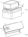
Fig. 2 is a perspective view of the assembly ofFig. 1 partially assembled; -
Fig. 3 is top view of the lower receiver of the receiver assembly ofFig. 1 ; -
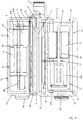
Fig. 4 is a cross-section view of the receiver assembly ofFig. 1 . -
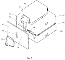
Fig. 5 is a perspective view of an example of a four driver three way setup according to aspects of the invention. - An example of an embodiment of a receiver assembly 1 according to the invention is shown in
Fig. 1 . A method for assembling the receiver assembly 1 comprises providing afirst receiver housing 2 comprising a firstsound outlet port 3 and asecond receiver housing 4 comprising a secondsound outlet port 5. Further provided are aspout 6, anacoustic duct 7 and anacoustic mass 8. Thesecond receiver housing 4 is positioned over the firstsound outlet port 3 of thefirst receiver housing 2, while theacoustic duct 7 is positioned between thefirst receiver housing 2 and the second receiver housing 4. Theacoustic duct 7 is positioned such that it is located over the firstsound outlet port 3 of thefirst receiver 2, acoustically connected with the firstsound outlet port 3, and that end portion of theacoustic duct 7 is located near the secondsound outlet port 5 of thesecond receiver housing 4. Theacoustic mass 8 is positioned in the end portion of theacoustic duct 7 and aspout 6 is placed over the secondsound outlet port 5 and the end portion of theacoustic duct 7. In this embodiment, theacoustic duct 7 is provided as a spacer member, i.e. aplate 9 having a certain thickness d, wherein a cut-out portion constitutes theacoustic duct 7 when it is positioned between thereceiver housings Fig. 2 shows the assembledreceiver housings plate 9 in-between. Prior to positioning theacoustic duct 7 between thefirst receiver housing 2 and thesecond receiver housing 4, theacoustic duct 7, in this embodiment theplate 9, is mounted to thesecond receiver housing 4 such that the end portion of theacoustic duct 7 is located near the secondsound outlet port 5 of thesecond receiver housing 4. This makes it easier to position theacoustic mass 8 in the end portion of theacoustic duct 7. Glue is applied to fixate theacoustic mass 8, filling any clefts left between the outer side of theacoustic mass 8 and the inner side of theacoustic duct 7. This also prevents any sound coming from the firstsound outlet port 3 from circumventing theacoustic mass 8. Once glued, thespout 6 can be mounted over the secondsound outlet port 5, in this embodiment shaped as a slit, and theoutlet 13 ofacoustic mass 8. - The according to the above obtained assembly 1 comprises
first receiver housing 2 comprising a firstsound outlet port 3,second receiver housing 4 comprising secondsound outlet port 5 and aspout 6. In the assembly thesecond receiver housing 4 is positioned over the firstsound outlet port 3, while thespout 6 is positioned over thesecond outlet port 5. Furthermore, theacoustic duct 7 is located between thefirst receiver housing 2 and thesecond receiver housing 4 and acoustically connects the firstsound outlet port 3 to thespout 6. Theacoustic mass 8 is positioned in the end portion of theacoustic duct 7 close to thespout 6. In this embodiment, theacoustic mass 8 comprises a tube in cross-section having an inner contour of circular shape. However, other cross-sectional shapes as square or hexagonal shapes are also possible. The outer diameter of the tube corresponds to the inner diameter of the end portion of theacoustic duct 7. The choice for the dimensions of the tube, length and inner diameter, depends on the desired corner frequency. Especially the inner diameter is set for tuning the corner frequency, e.g. an inner diameter of 0.1 mm results in a corner frequency 100 Hz (subwoofer), while 0.2 mm results in a corner frequency 1 kHz. The inner diameter is usually selected from 0.1 to 0.7 mm. The length can be chosen anywhere between 0.5 and 5 mm. -
Fig 3 shows the firstsound outlet port 3, in this embodiment a circular shaped hole inreceiver housing 2, acoustically connected to achamber 10 of theacoustic duct 7. Thechamber 10 preferably has a diameter larger than the diameter of the firstsound outlet port 3. Theacoustic duct 7 further comprises apassage 11 that runs from thechamber 10 to the side of the receiver assembly 1 where thespout 6 is to be mounted; accordingly when thespout 6 is mounted thepassage 11 runs towards thespout 6. At the end ofpassage 11 running towards the spout 6 arecess 12 is left out, which aims to prevent glue from running into thetube 8 when being fixated in thepassage 11. In another embodiment, it may suffice to have the diameter of thepassage 11 expand at the edge ofplate 9. - As best seen in
Fig. 3 the acoustic duct is provided as cut-out portion inplate 9, wherein the cut-out portion constitutes thechamber 10, thepassage 11 andrecess 12. In another embodiment, the acoustic duct may be provided in the outer surface of the first orsecond receiver housing 2 ,4: e.g. as a cut-out or grooved portion. In yet another embodiment, corresponding cut-out portions may be provided in the surface of both receiver housings which when assembled constitute the acoustic duct. -
Plate 9 operates as a spacer member, providing a predetermined distance between thereceiver housings tube 8. This allows the use of off-the-shelf receivers without the necessity of adapting the surface of the receiver housings or other additional measures to be able to position the acoustic mass between the receiver housings. Furthermore, the plate can be provided with means for attaching the receiver assembly to the inside of the casing of an earphone or hearing aid, thus functioning as a bracket member. - In the receiver assembly 1, the
first receiver housing 2 preferably comprises a woofer transducer assembly and thesecond receiver housing 4 preferably comprises a mid-range transducer assembly or a tweeter transducer assembly. Thus, the receiver assembly operates as woofer-midrange or woofer-tweeter dual receiver assembly. - Referring to
fig. 4 there is shown a cross-section of the receiver assembly along line A-A' as shown inFig. 1 . Shown are the transducer assemblies located respectively in the first andsecond receiver housings first receiver housing 2 houses awoofer transducer assembly 14 designed for producing sounds in the bass region of the audio spectrum. Thewoofer transducer assembly 14 comprises amotor assembly 15 driving adiaphragm 16 through a drivingpin 17. Themotor assembly 15 comprises acoil wire 18 wound around abobbin 19, anarmature 20 of U-shaped type and amagnet assembly 21. The magnet assembly comprises amagnet housing 22 and a pair ofmagnets case 24 and acover 25. Thecase 24 is provided withconnectors 26 for connecting a source of electric signals, representing e.g. audio signals for playback, to thetransducer assembly 14. - The
second receiver housing 4 houses atweeter transducer assembly 34 designed for producing sounds in the upper region of the audio spectrum. Thetweeter transducer assembly 34 comprises amotor assembly 35 driving adiaphragm 36 through a drivingpin 37. Themotor assembly 35 comprises acoil wire 38 wound around abobbin 39, anarmature 40 of the E-shaped type and amagnet assembly 41. The magnet assembly comprises amagnet housing 42 and a pair ofmagnets second receiver housing 4 is made up of acase 44 and acover 45. Thecase 44 is provided withconnectors 46 for connecting a source of electric signals, representing e.g. audio signals for playback, to thetransducer assembly 34. - The transducer assemblies operate as follows. Electric audio signals are transferred to each
motor assembly coils respective armatures respective diaphragms diaphragms - As explained above, between the first and
second receiver housing plate 9 is positioned withchamber 10 acoustically connected to the firstsound outlet port 3. The sound produced by thewoofer transducer assembly 14 in thefirst receiver housing 2 passes through theacoustic duct 7 and through thetube 8. Thetube 8 acts as acoustic impedance and thus operates as acoustic low pass filter with a predetermined corner frequency corresponding to the design and dimensions of thetube 8. The filtered sound of the woofer assembly is joined with the sound of the tweeter assembly within thespout 6 and can travel further through a single sound channel. -
Fig. 5 shows a four driver three way setup having four drivers i.e. transducers producing three different frequency spectra. This receiver assembly has a dualwoofer receiver assembly 101, amid-range receiver 52 and atweeter receiver 50. Thetweeter receiver 50 has aseparate spout 51. Themid-range receiver 52 has asound outlet port 53. Thedual woofer assembly 101 has afirst woofer receiver 102 and asecond woofer receiver 104. The sound outlet ports of bothwoofer receivers tube 108 is located in theacoustic duct 107. A plate orbracket 54 is positioned over the front of the dualwoofer receiver assembly 101 and mid-range receiver. Theplate 54 has aslit 55 for passing sound from thesound outlet port 53 of the mid-range receiver and ahole 56 through whichtube 108 is placed. The inner diameter ofhole 56 is adapted to the outer diameter of thetube 108 to provide n acoustically sealing fit. Aspout 106 is positioned over theslit 55 andtube 108 extending throughhole 56. - Each of these embodiments is contemplated as falling within the scope of the invention as defined in the appended claims.
Claims (13)
- A receiver assembly, comprising:a first receiver housing (2, 102) comprising a first sound outlet port (3);a second receiver housing (4, 104) comprising a second sound outlet port (5);a spout (6, 106);wherein the second receiver housing (4,104) is positioned over the first sound outlet port (3);further comprising an acoustic duct (7, 107) located between the first (2,102) and second receiver housing (4,104) acoustically connecting the first sound outlet port (3) to the spout (6); andan acoustic mass (8, 108) positioned in an end portion of the acoustic duct (7, 107) close to the spout (6,106);characterised in that the acoustic duct (7, 107) is provided as a plate (9) with a cut-out portion, said cut-out portion constituting the acoustic duct.
- A receiver assembly according to claim 1, wherein the acoustic mass comprises a tube (8, 108).
- A receiver assembly according to claim 1 or 2, wherein the acoustic mass (8, 108) has an outer diameter corresponding to the inner diameter of the end portion of the acoustic duct (7, 107).
- A receiver assembly according to any of the preceding claims, wherein the acoustic mass (8, 108) in cross-section has an inner contour of circular shape.
- A receiver assembly according to any of the preceding claims, wherein the acoustic mass (8, 108) has an inner diameter between 0.1 and 0.7 mm.
- A receiver assembly according to any of the preceding claims, wherein the acoustic duct (7, 107) comprises a chamber (10) and a passage (11), wherein the passage (11) runs from the chamber (10) towards the spout (6).
- A receiver assembly according to any of the preceding claims, wherein the first sound outlet port (3) is a circular shaped hole in the first receiver housing.
- A receiver assembly according to any of the preceding claims, wherein the second outlet port (5) is acoustically connected directly to the spout (6, 106).
- A receiver assembly according to any of the preceding claims, wherein the first receiver housing (2, 102) comprises a woofer transducer assembly; and
wherein the second receiver housing (4, 104) comprises a mid-range transducer assembly or a tweeter transducer assembly. - A receiver assembly according to any of the claims 1 - 7, wherein the second outlet port (5) is acoustically connected to the acoustic duct (7, 107).
- A receiver assembly according to claim 10, wherein the first (2, 102) and second receiver housing (4, 104) each comprise a woofer transducer assembly.
- A method for assembling a receiver assembly, comprising:providing a first receiver housing (2, 102) comprising a first sound outlet port (3), a second receiver housing (4, 104) comprising a second sound outlet port (5) and providing an acoustic duct (7, 107);positioning the second receiver housing (4, 104) over the sound outlet port (3) of the first receiver housing (2, 102);positioning the acoustic duct (8, 108) between the first (2, 102) and second receiver housing (4, 104) such that it is located over the first sound outlet port (3) of the first receiver housing (2, 102) and acoustically connected with the first sound outlet port (3) and that an end portion of the acoustic duct (7, 107) is located near the second sound outlet port (5);positioning an acoustic mass (8, 108) in the end portion of the acoustic duct (7, 107); andplacing a spout (6, 106) over the second sound outlet port (5) and the end portion of the acoustic duct (7, 107),characterised in that the method further comprises providing the acoustic duct (7, 107) as a plate (9) with a cut-out portion, said cut-out portion constituting the acoustic duct; and prior to positioning the acoustic duct (7, 107) between the first (2, 102) and second receiver housing (4, 104), mounting the acoustic duct (7, 107) to the second receiver housing (4, 104) such that the end portion of the acoustic duct is located near the second sound outlet port (3) of the second receiver housing (4, 104).
- A method for assembling a receiver assembly according to claim 12, further comprising: applying glue to fixate the acoustic mass (8, 108).
Applications Claiming Priority (2)
| Application Number | Priority Date | Filing Date | Title |
|---|---|---|---|
| US201161505300P | 2011-07-07 | 2011-07-07 | |
| PCT/EP2012/062724 WO2013004623A1 (en) | 2011-07-07 | 2012-06-29 | A multiple receiver assembly and a method for assembly thereof |
Publications (2)
| Publication Number | Publication Date |
|---|---|
| EP2730097A1 EP2730097A1 (en) | 2014-05-14 |
| EP2730097B1 true EP2730097B1 (en) | 2019-09-18 |
Family
ID=46456583
Family Applications (1)
| Application Number | Title | Priority Date | Filing Date |
|---|---|---|---|
| EP12731439.1A Active EP2730097B1 (en) | 2011-07-07 | 2012-06-29 | A multiple receiver assembly and a method for assembly thereof |
Country Status (4)
| Country | Link |
|---|---|
| US (3) | US9357287B2 (en) |
| EP (1) | EP2730097B1 (en) |
| DK (1) | DK2730097T3 (en) |
| WO (1) | WO2013004623A1 (en) |
Families Citing this family (12)
| Publication number | Priority date | Publication date | Assignee | Title |
|---|---|---|---|---|
| US9210521B2 (en) | 2012-07-16 | 2015-12-08 | Sophono, Inc. | Abutment attachment systems, mechanisms, devices, components and methods for bone conduction hearing aids |
| US9736601B2 (en) | 2012-07-16 | 2017-08-15 | Sophono, Inc. | Adjustable magnetic systems, devices, components and methods for bone conduction hearing aids |
| US9258656B2 (en) * | 2011-12-09 | 2016-02-09 | Sophono, Inc. | Sound acquisition and analysis systems, devices and components for magnetic hearing aids |
| US9526810B2 (en) | 2011-12-09 | 2016-12-27 | Sophono, Inc. | Systems, devices, components and methods for improved acoustic coupling between a bone conduction hearing device and a patient's head or skull |
| US9055366B2 (en) * | 2013-01-22 | 2015-06-09 | Apple Inc. | Multi-driver earbud |
| JP2015080064A (en) * | 2013-10-16 | 2015-04-23 | モレックス インコーポレイテドMolex Incorporated | Electroacoustic transducer |
| DK3550852T3 (en) | 2014-02-14 | 2021-02-01 | Sonion Nederland Bv | A joiner for a receiver assembly |
| US9432774B2 (en) * | 2014-04-02 | 2016-08-30 | Sonion Nederland B.V. | Transducer with a bent armature |
| US9872109B2 (en) | 2014-12-17 | 2018-01-16 | Knowles Electronics, Llc | Shared coil receiver |
| DK3337184T3 (en) | 2016-12-14 | 2020-06-02 | Sonion Nederland Bv | An armature and a transducer comprising the armature |
| CN110313186B (en) * | 2017-01-05 | 2021-07-06 | 美商楼氏电子有限公司 | Acoustic devices, acoustic receivers and integrated circuits |
| US20240251212A1 (en) | 2018-10-22 | 2024-07-25 | Knowles Electronics, Llc | Diagnostics for acoustic devices and methods |
Citations (6)
| Publication number | Priority date | Publication date | Assignee | Title |
|---|---|---|---|---|
| WO2007022773A1 (en) * | 2005-08-23 | 2007-03-01 | Widex A/S | Hearing aid with increased acoustic bandwidth |
| US20070053540A1 (en) * | 2005-09-07 | 2007-03-08 | Ultimate Ears, Llc | Earpiece with acoustic vent for driver response optimization |
| US20070223735A1 (en) * | 2006-03-27 | 2007-09-27 | Knowles Electronics, Llc | Electroacoustic Transducer System and Manufacturing Method Thereof |
| EP1895811A2 (en) * | 2006-08-28 | 2008-03-05 | Sonion Nederland B.V. | Multiple receivers with a common acoustic spout |
| US20090060245A1 (en) * | 2007-08-30 | 2009-03-05 | Mark Alan Blanchard | Balanced armature with acoustic low pass filter |
| EP2166779A2 (en) * | 2008-09-18 | 2010-03-24 | Sonion Nederland B.V. | An apparatus for outputting sound comprising multiple receivers and a common output channel |
Family Cites Families (78)
| Publication number | Priority date | Publication date | Assignee | Title |
|---|---|---|---|---|
| NL1009544C2 (en) | 1998-07-02 | 2000-01-10 | Microtronic Nederland Bv | System consisting of a microphone and a preamp. |
| PL346751A1 (en) | 1998-09-24 | 2002-02-25 | Microtronic As | A hearing aid adapted for discrete operation |
| US7706561B2 (en) | 1999-04-06 | 2010-04-27 | Sonion Nederland B.V. | Electroacoustic transducer with a diaphragm and method for fixing a diaphragm in such transducer |
| NL1011733C1 (en) | 1999-04-06 | 2000-10-09 | Microtronic Nederland Bv | Electroacoustic transducer with a membrane and method for mounting a membrane in such a transducer. |
| NL1011778C1 (en) | 1999-04-13 | 2000-10-16 | Microtronic Nederland Bv | Microphone for a hearing aid and a hearing aid provided with such a microphone. |
| EP1192629B1 (en) | 1999-06-10 | 2004-03-03 | Sonion A/S | Encoder |
| US6522762B1 (en) | 1999-09-07 | 2003-02-18 | Microtronic A/S | Silicon-based sensor system |
| DE60128808T2 (en) | 2000-06-30 | 2008-02-07 | Sonion Nederland B.V. | A MICROPHONE ASSEMBLY |
| US7181035B2 (en) | 2000-11-22 | 2007-02-20 | Sonion Nederland B.V. | Acoustical receiver housing for hearing aids |
| TW510139B (en) | 2001-01-26 | 2002-11-11 | Kirk Acoustics As | An electroacoustic transducer and a coil and a magnet circuit therefor |
| US6831577B1 (en) | 2001-02-02 | 2004-12-14 | Sonion A/S | Sigma delta modulator having enlarged dynamic range due to stabilized signal swing |
| WO2002073792A2 (en) | 2001-03-09 | 2002-09-19 | Techtronic A/S | An electret condensor microphone preamplifier that is insensitive to leakage currents at the input |
| JP2002300698A (en) * | 2001-04-02 | 2002-10-11 | Star Micronics Co Ltd | Receivers and portable communication devices |
| EP1248496A3 (en) | 2001-04-04 | 2005-11-02 | Sonionmicrotronic Nederland B.V. | Aucoustic receiver having improved mechanical suspension |
| US7136496B2 (en) | 2001-04-18 | 2006-11-14 | Sonion Nederland B.V. | Electret assembly for a microphone having a backplate with improved charge stability |
| US7062058B2 (en) | 2001-04-18 | 2006-06-13 | Sonion Nederland B.V. | Cylindrical microphone having an electret assembly in the end cover |
| US6859542B2 (en) | 2001-05-31 | 2005-02-22 | Sonion Lyngby A/S | Method of providing a hydrophobic layer and a condenser microphone having such a layer |
| US7227968B2 (en) | 2001-06-25 | 2007-06-05 | Sonion Roskilde A/S | Expandsible Receiver Module |
| DK1278220T3 (en) | 2001-07-20 | 2011-03-07 | Sonion As | Switch / volume control unit for a hearing aid |
| US6788796B1 (en) | 2001-08-01 | 2004-09-07 | The Research Foundation Of The State University Of New York | Differential microphone |
| US7239714B2 (en) | 2001-10-09 | 2007-07-03 | Sonion Nederland B.V. | Microphone having a flexible printed circuit board for mounting components |
| US20030094353A1 (en) | 2001-10-10 | 2003-05-22 | Soren Ravnkilde | Multifunctional switch |
| CN100524568C (en) | 2001-10-10 | 2009-08-05 | 桑尼昂微电子公司 | Digital pulse generator assembly and mobile device comprising the same |
| DE60214417T2 (en) | 2001-11-30 | 2007-10-18 | Sonion A/S | HIGHLY EFFICIENT DRIVER FOR MINIATURE SPEAKERS |
| KR20040081470A (en) | 2002-01-25 | 2004-09-21 | 소니온 호르젠스 에이/에스 | Flexible diaphragm with integrated coil |
| US7190803B2 (en) | 2002-04-09 | 2007-03-13 | Sonion Nederland Bv | Acoustic transducer having reduced thickness |
| US6888408B2 (en) | 2002-08-27 | 2005-05-03 | Sonion Tech A/S | Preamplifier for two terminal electret condenser microphones |
| US7072482B2 (en) | 2002-09-06 | 2006-07-04 | Sonion Nederland B.V. | Microphone with improved sound inlet port |
| US7292876B2 (en) | 2002-10-08 | 2007-11-06 | Sonion Nederland B.V. | Digital system bus for use in low power instruments such as hearing aids and listening devices |
| US8280082B2 (en) | 2002-10-08 | 2012-10-02 | Sonion Nederland B.V. | Electret assembly for a microphone having a backplate with improved charge stability |
| US7142682B2 (en) | 2002-12-20 | 2006-11-28 | Sonion Mems A/S | Silicon-based transducer for use in hearing instruments and listening devices |
| EP1434464B1 (en) | 2002-12-23 | 2008-04-30 | Sonion Roskilde A/S | Encapsulated receiver comprising an expansible means such as a balloon |
| US7008271B2 (en) | 2003-02-20 | 2006-03-07 | Sonion Roskilde A/S | Female connector assembly with a displaceable conductor |
| ATE329362T1 (en) | 2003-03-04 | 2006-06-15 | Sonion Roskilde As | COMBINED ROLLER AND KEY SWITCH |
| US7466835B2 (en) | 2003-03-18 | 2008-12-16 | Sonion A/S | Miniature microphone with balanced termination |
| DE10316287B3 (en) | 2003-04-09 | 2004-07-15 | Siemens Audiologische Technik Gmbh | Directional microphone for hearing aid having 2 acoustically coupled membranes each coupled to respective sound entry opening |
| ATE401759T1 (en) | 2003-05-01 | 2008-08-15 | Sonion Roskilde As | INSERT MODULE FOR MINIATURE HEARING AID |
| US7012200B2 (en) | 2004-02-13 | 2006-03-14 | Sonion Roskilde A/S | Integrated volume control and switch assembly |
| WO2005115053A1 (en) | 2004-05-14 | 2005-12-01 | Sonion Nederland B.V. | Dual diaphragm electroacoustic transducer |
| EP1599067B1 (en) | 2004-05-21 | 2013-05-01 | Epcos Pte Ltd | Detection and control of diaphragm collapse in condenser microphones |
| EP1613125A3 (en) | 2004-07-02 | 2008-10-22 | Sonion Nederland B.V. | Microphone assembly comprising magnetically activable element for signal switching and field indication |
| US7460681B2 (en) | 2004-07-20 | 2008-12-02 | Sonion Nederland B.V. | Radio frequency shielding for receivers within hearing aids and listening devices |
| EP1626612A3 (en) | 2004-08-11 | 2009-05-06 | Sonion Nederland B.V. | Hearing aid microphone mounting structure and method for mounting |
| EP1638366B1 (en) | 2004-09-20 | 2015-08-26 | Sonion Nederland B.V. | A microphone assembly |
| US7415121B2 (en) | 2004-10-29 | 2008-08-19 | Sonion Nederland B.V. | Microphone with internal damping |
| DK2416589T3 (en) | 2004-11-01 | 2018-03-12 | Sonion Nederland Bv | Electroacoustic transducer and transducer device |
| DE602006020645D1 (en) | 2005-01-10 | 2011-04-28 | Sonion Nederland Bv | Assembly of an electroacoustic transducer in trays of personal communication devices |
| US7747032B2 (en) * | 2005-05-09 | 2010-06-29 | Knowles Electronics, Llc | Conjoined receiver and microphone assembly |
| EP1742506B1 (en) | 2005-07-06 | 2013-05-22 | Epcos Pte Ltd | Microphone assembly with P-type preamplifier input stage |
| US7899203B2 (en) | 2005-09-15 | 2011-03-01 | Sonion Nederland B.V. | Transducers with improved viscous damping |
| EP1814356B1 (en) | 2006-01-26 | 2010-03-24 | Sonion MEMS A/S | An elastomeric shield for miniature microphones |
| EP1852882A3 (en) | 2006-05-01 | 2009-07-29 | Sonion Roskilde A/S | A multi-functional control |
| US8170249B2 (en) | 2006-06-19 | 2012-05-01 | Sonion Nederland B.V. | Hearing aid having two receivers each amplifying a different frequency range |
| US8259977B2 (en) | 2006-11-21 | 2012-09-04 | Sonion A/Sb | Connector assembly comprising a first part and a second part attachable to and detachable from each other |
| DE112007003083B4 (en) | 2006-12-22 | 2019-05-09 | Tdk Corp. | Microphone assembly with underfill with low coefficient of thermal expansion |
| DK1962551T3 (en) | 2007-02-20 | 2014-07-14 | Sonion Nederland Bv | Sound transmitter with movable luminaire |
| US8391534B2 (en) | 2008-07-23 | 2013-03-05 | Asius Technologies, Llc | Inflatable ear device |
| US8160290B2 (en) | 2007-09-04 | 2012-04-17 | Sonion A/S | Electroacoustic transducer having a slotted terminal structure for connection to a flexible wire, and an assembly of the same |
| EP2046072A3 (en) | 2007-10-01 | 2009-11-04 | Sonion Nederland B.V. | A microphone assembly with a replaceable part |
| DK2071866T3 (en) | 2007-12-14 | 2017-07-24 | Sonion As | Removable earpiece sound system with spring control |
| US8189804B2 (en) | 2007-12-19 | 2012-05-29 | Sonion Nederland B.V. | Sound provider adapter to cancel out noise |
| US8259976B2 (en) | 2008-04-02 | 2012-09-04 | Sonion Nederland B.V. | Assembly comprising a sound emitter and two sound detectors |
| US8101876B2 (en) | 2008-04-22 | 2012-01-24 | Sonion Aps | Electro-mechanical pulse generator |
| DK2134107T3 (en) | 2008-06-11 | 2013-10-14 | Sonion Nederland Bv | Method of operating a hearing aid with improved ventilation |
| US8526651B2 (en) | 2010-01-25 | 2013-09-03 | Sonion Nederland Bv | Receiver module for inflating a membrane in an ear device |
| US8313336B2 (en) | 2010-02-01 | 2012-11-20 | Sonion A/S | Assembly comprising a male and a female plug member, a male plug member and a female plug member |
| US7946890B1 (en) | 2010-02-02 | 2011-05-24 | Sonion A/S | Adapter for an electronic assembly |
| EP2393311A1 (en) | 2010-06-07 | 2011-12-07 | Sonion A/S | A cerumen filter for a hearing aid |
| DK2393312T3 (en) | 2010-06-07 | 2014-10-27 | Sonion As | Method of forming a connector for a hearing aid |
| US8885859B2 (en) | 2010-07-16 | 2014-11-11 | Sonion Nederland Bv | Semi-permanent hearing aid |
| US8712084B2 (en) | 2010-12-07 | 2014-04-29 | Sonion Nederland Bv | Motor assembly |
| EP3048810B1 (en) * | 2010-12-14 | 2019-03-20 | Sonion Nederland B.V. | Multi-layer armature for moving armature receiver |
| EP2469705B1 (en) | 2010-12-21 | 2015-12-02 | Sonion Nederland B.V. | Generation of a supply voltage from output of a class-D audio amplifier |
| DK2503792T3 (en) | 2011-03-21 | 2018-08-20 | Sonion Nederland Bv | Speaker device with movable luminaire with vibration suppression |
| EP2552128A1 (en) | 2011-07-29 | 2013-01-30 | Sonion Nederland B.V. | A dual cartridge directional microphone |
| US9055380B2 (en) | 2011-11-28 | 2015-06-09 | Sonion Nederland B.V. | Method for producing a tube for a hearing aid |
| DK2608576T3 (en) | 2011-12-21 | 2020-03-30 | Sonion Nederland Bv | An apparatus and a method for providing sound |
| US8971554B2 (en) | 2011-12-22 | 2015-03-03 | Sonion Nederland Bv | Hearing aid with a sensor for changing power state of the hearing aid |
-
2012
- 2012-06-29 US US14/130,450 patent/US9357287B2/en active Active
- 2012-06-29 EP EP12731439.1A patent/EP2730097B1/en active Active
- 2012-06-29 DK DK12731439T patent/DK2730097T3/en active
- 2012-06-29 WO PCT/EP2012/062724 patent/WO2013004623A1/en not_active Ceased
-
2016
- 2016-04-29 US US15/142,960 patent/US9854361B2/en active Active
-
2017
- 2017-03-20 US US15/463,939 patent/US9877102B2/en active Active
Patent Citations (6)
| Publication number | Priority date | Publication date | Assignee | Title |
|---|---|---|---|---|
| WO2007022773A1 (en) * | 2005-08-23 | 2007-03-01 | Widex A/S | Hearing aid with increased acoustic bandwidth |
| US20070053540A1 (en) * | 2005-09-07 | 2007-03-08 | Ultimate Ears, Llc | Earpiece with acoustic vent for driver response optimization |
| US20070223735A1 (en) * | 2006-03-27 | 2007-09-27 | Knowles Electronics, Llc | Electroacoustic Transducer System and Manufacturing Method Thereof |
| EP1895811A2 (en) * | 2006-08-28 | 2008-03-05 | Sonion Nederland B.V. | Multiple receivers with a common acoustic spout |
| US20090060245A1 (en) * | 2007-08-30 | 2009-03-05 | Mark Alan Blanchard | Balanced armature with acoustic low pass filter |
| EP2166779A2 (en) * | 2008-09-18 | 2010-03-24 | Sonion Nederland B.V. | An apparatus for outputting sound comprising multiple receivers and a common output channel |
Also Published As
| Publication number | Publication date |
|---|---|
| US20140153737A1 (en) | 2014-06-05 |
| US20170245048A1 (en) | 2017-08-24 |
| US9877102B2 (en) | 2018-01-23 |
| US9357287B2 (en) | 2016-05-31 |
| US9854361B2 (en) | 2017-12-26 |
| DK2730097T3 (en) | 2019-12-09 |
| WO2013004623A1 (en) | 2013-01-10 |
| US20160323670A1 (en) | 2016-11-03 |
| EP2730097A1 (en) | 2014-05-14 |
Similar Documents
| Publication | Publication Date | Title |
|---|---|---|
| US9877102B2 (en) | Transducer assembly with acoustic mass | |
| US8135163B2 (en) | Balanced armature with acoustic low pass filter | |
| JP6275125B2 (en) | Earphone assembly and method for filtering sound output in earphone | |
| US9716942B2 (en) | Mitigating effects of cavity resonance in speakers | |
| EP2983378A1 (en) | Dual-frequency coaxial earphone | |
| KR101092958B1 (en) | Ear set | |
| JPH0644838B2 (en) | Speaker device | |
| JP2019145962A (en) | earphone | |
| US20160219360A1 (en) | Earphone | |
| US9578403B2 (en) | 2-way speaker with coaxial effect | |
| EP3157267A1 (en) | Loudspeaker | |
| JP6379239B2 (en) | Speaker module for listening device and listening device | |
| CN220985821U (en) | Open Headphones | |
| KR101828262B1 (en) | Balanced armature type speaker | |
| EP3395080B1 (en) | Conformable adaptors for diffraction slots in speakers | |
| KR101634236B1 (en) | Acoustic Hybrid Earphone With Acoustic Filter | |
| EP4262230A1 (en) | Earphone | |
| WO2022170972A1 (en) | Hybrid speaker and audio reproduction device | |
| JPH0646839B2 (en) | Speaker device | |
| CN223157205U (en) | A multi-unit earphone mounting structure and a multi-unit hybrid earphone | |
| CN115499757B (en) | earphone | |
| KR102543007B1 (en) | 2-way receiver with flat tweeter diaphragm | |
| KR102741565B1 (en) | Earphones to improve sense of space | |
| KR20030055814A (en) | Two channel integration and thin type speaker | |
| WO2025227890A1 (en) | Earphone |
Legal Events
| Date | Code | Title | Description |
|---|---|---|---|
| PUAI | Public reference made under article 153(3) epc to a published international application that has entered the european phase |
Free format text: ORIGINAL CODE: 0009012 |
|
| 17P | Request for examination filed |
Effective date: 20140207 |
|
| AK | Designated contracting states |
Kind code of ref document: A1 Designated state(s): AL AT BE BG CH CY CZ DE DK EE ES FI FR GB GR HR HU IE IS IT LI LT LU LV MC MK MT NL NO PL PT RO RS SE SI SK SM TR |
|
| DAX | Request for extension of the european patent (deleted) | ||
| 17Q | First examination report despatched |
Effective date: 20151027 |
|
| STAA | Information on the status of an ep patent application or granted ep patent |
Free format text: STATUS: EXAMINATION IS IN PROGRESS |
|
| GRAP | Despatch of communication of intention to grant a patent |
Free format text: ORIGINAL CODE: EPIDOSNIGR1 |
|
| STAA | Information on the status of an ep patent application or granted ep patent |
Free format text: STATUS: GRANT OF PATENT IS INTENDED |
|
| RIC1 | Information provided on ipc code assigned before grant |
Ipc: H04R 1/26 20060101AFI20190307BHEP Ipc: H04R 5/033 20060101ALN20190307BHEP Ipc: H04R 25/00 20060101ALN20190307BHEP Ipc: H04R 1/34 20060101ALN20190307BHEP Ipc: H04R 1/28 20060101ALN20190307BHEP Ipc: H04R 31/00 20060101ALN20190307BHEP Ipc: H04R 11/06 20060101ALN20190307BHEP |
|
| INTG | Intention to grant announced |
Effective date: 20190329 |
|
| GRAS | Grant fee paid |
Free format text: ORIGINAL CODE: EPIDOSNIGR3 |
|
| GRAA | (expected) grant |
Free format text: ORIGINAL CODE: 0009210 |
|
| STAA | Information on the status of an ep patent application or granted ep patent |
Free format text: STATUS: THE PATENT HAS BEEN GRANTED |
|
| AK | Designated contracting states |
Kind code of ref document: B1 Designated state(s): AL AT BE BG CH CY CZ DE DK EE ES FI FR GB GR HR HU IE IS IT LI LT LU LV MC MK MT NL NO PL PT RO RS SE SI SK SM TR |
|
| REG | Reference to a national code |
Ref country code: GB Ref legal event code: FG4D |
|
| REG | Reference to a national code |
Ref country code: CH Ref legal event code: EP |
|
| REG | Reference to a national code |
Ref country code: DE Ref legal event code: R096 Ref document number: 602012064102 Country of ref document: DE |
|
| REG | Reference to a national code |
Ref country code: AT Ref legal event code: REF Ref document number: 1182720 Country of ref document: AT Kind code of ref document: T Effective date: 20191015 |
|
| REG | Reference to a national code |
Ref country code: IE Ref legal event code: FG4D |
|
| REG | Reference to a national code |
Ref country code: DK Ref legal event code: T3 Effective date: 20191203 |
|
| REG | Reference to a national code |
Ref country code: NL Ref legal event code: MP Effective date: 20190918 |
|
| PG25 | Lapsed in a contracting state [announced via postgrant information from national office to epo] |
Ref country code: LT Free format text: LAPSE BECAUSE OF FAILURE TO SUBMIT A TRANSLATION OF THE DESCRIPTION OR TO PAY THE FEE WITHIN THE PRESCRIBED TIME-LIMIT Effective date: 20190918 Ref country code: BG Free format text: LAPSE BECAUSE OF FAILURE TO SUBMIT A TRANSLATION OF THE DESCRIPTION OR TO PAY THE FEE WITHIN THE PRESCRIBED TIME-LIMIT Effective date: 20191218 Ref country code: SE Free format text: LAPSE BECAUSE OF FAILURE TO SUBMIT A TRANSLATION OF THE DESCRIPTION OR TO PAY THE FEE WITHIN THE PRESCRIBED TIME-LIMIT Effective date: 20190918 Ref country code: NO Free format text: LAPSE BECAUSE OF FAILURE TO SUBMIT A TRANSLATION OF THE DESCRIPTION OR TO PAY THE FEE WITHIN THE PRESCRIBED TIME-LIMIT Effective date: 20191218 Ref country code: HR Free format text: LAPSE BECAUSE OF FAILURE TO SUBMIT A TRANSLATION OF THE DESCRIPTION OR TO PAY THE FEE WITHIN THE PRESCRIBED TIME-LIMIT Effective date: 20190918 Ref country code: FI Free format text: LAPSE BECAUSE OF FAILURE TO SUBMIT A TRANSLATION OF THE DESCRIPTION OR TO PAY THE FEE WITHIN THE PRESCRIBED TIME-LIMIT Effective date: 20190918 |
|
| REG | Reference to a national code |
Ref country code: LT Ref legal event code: MG4D |
|
| PG25 | Lapsed in a contracting state [announced via postgrant information from national office to epo] |
Ref country code: GR Free format text: LAPSE BECAUSE OF FAILURE TO SUBMIT A TRANSLATION OF THE DESCRIPTION OR TO PAY THE FEE WITHIN THE PRESCRIBED TIME-LIMIT Effective date: 20191219 Ref country code: LV Free format text: LAPSE BECAUSE OF FAILURE TO SUBMIT A TRANSLATION OF THE DESCRIPTION OR TO PAY THE FEE WITHIN THE PRESCRIBED TIME-LIMIT Effective date: 20190918 Ref country code: RS Free format text: LAPSE BECAUSE OF FAILURE TO SUBMIT A TRANSLATION OF THE DESCRIPTION OR TO PAY THE FEE WITHIN THE PRESCRIBED TIME-LIMIT Effective date: 20190918 Ref country code: AL Free format text: LAPSE BECAUSE OF FAILURE TO SUBMIT A TRANSLATION OF THE DESCRIPTION OR TO PAY THE FEE WITHIN THE PRESCRIBED TIME-LIMIT Effective date: 20190918 |
|
| REG | Reference to a national code |
Ref country code: AT Ref legal event code: MK05 Ref document number: 1182720 Country of ref document: AT Kind code of ref document: T Effective date: 20190918 |
|
| PG25 | Lapsed in a contracting state [announced via postgrant information from national office to epo] |
Ref country code: RO Free format text: LAPSE BECAUSE OF FAILURE TO SUBMIT A TRANSLATION OF THE DESCRIPTION OR TO PAY THE FEE WITHIN THE PRESCRIBED TIME-LIMIT Effective date: 20190918 Ref country code: PT Free format text: LAPSE BECAUSE OF FAILURE TO SUBMIT A TRANSLATION OF THE DESCRIPTION OR TO PAY THE FEE WITHIN THE PRESCRIBED TIME-LIMIT Effective date: 20200120 Ref country code: EE Free format text: LAPSE BECAUSE OF FAILURE TO SUBMIT A TRANSLATION OF THE DESCRIPTION OR TO PAY THE FEE WITHIN THE PRESCRIBED TIME-LIMIT Effective date: 20190918 Ref country code: AT Free format text: LAPSE BECAUSE OF FAILURE TO SUBMIT A TRANSLATION OF THE DESCRIPTION OR TO PAY THE FEE WITHIN THE PRESCRIBED TIME-LIMIT Effective date: 20190918 Ref country code: IT Free format text: LAPSE BECAUSE OF FAILURE TO SUBMIT A TRANSLATION OF THE DESCRIPTION OR TO PAY THE FEE WITHIN THE PRESCRIBED TIME-LIMIT Effective date: 20190918 Ref country code: ES Free format text: LAPSE BECAUSE OF FAILURE TO SUBMIT A TRANSLATION OF THE DESCRIPTION OR TO PAY THE FEE WITHIN THE PRESCRIBED TIME-LIMIT Effective date: 20190918 Ref country code: PL Free format text: LAPSE BECAUSE OF FAILURE TO SUBMIT A TRANSLATION OF THE DESCRIPTION OR TO PAY THE FEE WITHIN THE PRESCRIBED TIME-LIMIT Effective date: 20190918 Ref country code: NL Free format text: LAPSE BECAUSE OF FAILURE TO SUBMIT A TRANSLATION OF THE DESCRIPTION OR TO PAY THE FEE WITHIN THE PRESCRIBED TIME-LIMIT Effective date: 20190918 |
|
| PG25 | Lapsed in a contracting state [announced via postgrant information from national office to epo] |
Ref country code: SK Free format text: LAPSE BECAUSE OF FAILURE TO SUBMIT A TRANSLATION OF THE DESCRIPTION OR TO PAY THE FEE WITHIN THE PRESCRIBED TIME-LIMIT Effective date: 20190918 Ref country code: CZ Free format text: LAPSE BECAUSE OF FAILURE TO SUBMIT A TRANSLATION OF THE DESCRIPTION OR TO PAY THE FEE WITHIN THE PRESCRIBED TIME-LIMIT Effective date: 20190918 Ref country code: IS Free format text: LAPSE BECAUSE OF FAILURE TO SUBMIT A TRANSLATION OF THE DESCRIPTION OR TO PAY THE FEE WITHIN THE PRESCRIBED TIME-LIMIT Effective date: 20200224 Ref country code: SM Free format text: LAPSE BECAUSE OF FAILURE TO SUBMIT A TRANSLATION OF THE DESCRIPTION OR TO PAY THE FEE WITHIN THE PRESCRIBED TIME-LIMIT Effective date: 20190918 |
|
| REG | Reference to a national code |
Ref country code: DE Ref legal event code: R097 Ref document number: 602012064102 Country of ref document: DE |
|
| PLBE | No opposition filed within time limit |
Free format text: ORIGINAL CODE: 0009261 |
|
| STAA | Information on the status of an ep patent application or granted ep patent |
Free format text: STATUS: NO OPPOSITION FILED WITHIN TIME LIMIT |
|
| PG2D | Information on lapse in contracting state deleted |
Ref country code: IS |
|
| PG25 | Lapsed in a contracting state [announced via postgrant information from national office to epo] |
Ref country code: IS Free format text: LAPSE BECAUSE OF FAILURE TO SUBMIT A TRANSLATION OF THE DESCRIPTION OR TO PAY THE FEE WITHIN THE PRESCRIBED TIME-LIMIT Effective date: 20200119 |
|
| 26N | No opposition filed |
Effective date: 20200619 |
|
| PG25 | Lapsed in a contracting state [announced via postgrant information from national office to epo] |
Ref country code: SI Free format text: LAPSE BECAUSE OF FAILURE TO SUBMIT A TRANSLATION OF THE DESCRIPTION OR TO PAY THE FEE WITHIN THE PRESCRIBED TIME-LIMIT Effective date: 20190918 |
|
| PG25 | Lapsed in a contracting state [announced via postgrant information from national office to epo] |
Ref country code: MC Free format text: LAPSE BECAUSE OF FAILURE TO SUBMIT A TRANSLATION OF THE DESCRIPTION OR TO PAY THE FEE WITHIN THE PRESCRIBED TIME-LIMIT Effective date: 20190918 |
|
| GBPC | Gb: european patent ceased through non-payment of renewal fee |
Effective date: 20200629 |
|
| PG25 | Lapsed in a contracting state [announced via postgrant information from national office to epo] |
Ref country code: LU Free format text: LAPSE BECAUSE OF NON-PAYMENT OF DUE FEES Effective date: 20200629 |
|
| REG | Reference to a national code |
Ref country code: BE Ref legal event code: MM Effective date: 20200630 |
|
| PG25 | Lapsed in a contracting state [announced via postgrant information from national office to epo] |
Ref country code: IE Free format text: LAPSE BECAUSE OF NON-PAYMENT OF DUE FEES Effective date: 20200629 Ref country code: GB Free format text: LAPSE BECAUSE OF NON-PAYMENT OF DUE FEES Effective date: 20200629 Ref country code: FR Free format text: LAPSE BECAUSE OF NON-PAYMENT OF DUE FEES Effective date: 20200630 |
|
| PG25 | Lapsed in a contracting state [announced via postgrant information from national office to epo] |
Ref country code: BE Free format text: LAPSE BECAUSE OF NON-PAYMENT OF DUE FEES Effective date: 20200630 |
|
| PG25 | Lapsed in a contracting state [announced via postgrant information from national office to epo] |
Ref country code: TR Free format text: LAPSE BECAUSE OF FAILURE TO SUBMIT A TRANSLATION OF THE DESCRIPTION OR TO PAY THE FEE WITHIN THE PRESCRIBED TIME-LIMIT Effective date: 20190918 Ref country code: MT Free format text: LAPSE BECAUSE OF FAILURE TO SUBMIT A TRANSLATION OF THE DESCRIPTION OR TO PAY THE FEE WITHIN THE PRESCRIBED TIME-LIMIT Effective date: 20190918 Ref country code: CY Free format text: LAPSE BECAUSE OF FAILURE TO SUBMIT A TRANSLATION OF THE DESCRIPTION OR TO PAY THE FEE WITHIN THE PRESCRIBED TIME-LIMIT Effective date: 20190918 |
|
| PG25 | Lapsed in a contracting state [announced via postgrant information from national office to epo] |
Ref country code: MK Free format text: LAPSE BECAUSE OF FAILURE TO SUBMIT A TRANSLATION OF THE DESCRIPTION OR TO PAY THE FEE WITHIN THE PRESCRIBED TIME-LIMIT Effective date: 20190918 |
|
| PGFP | Annual fee paid to national office [announced via postgrant information from national office to epo] |
Ref country code: DE Payment date: 20250618 Year of fee payment: 14 |
|
| PGFP | Annual fee paid to national office [announced via postgrant information from national office to epo] |
Ref country code: DK Payment date: 20250625 Year of fee payment: 14 |
|
| PGFP | Annual fee paid to national office [announced via postgrant information from national office to epo] |
Ref country code: CH Payment date: 20250701 Year of fee payment: 14 |