EP2729630B1 - Food waste disposer with food deflecting housing - Google Patents
Food waste disposer with food deflecting housing Download PDFInfo
- Publication number
- EP2729630B1 EP2729630B1 EP12737969.1A EP12737969A EP2729630B1 EP 2729630 B1 EP2729630 B1 EP 2729630B1 EP 12737969 A EP12737969 A EP 12737969A EP 2729630 B1 EP2729630 B1 EP 2729630B1
- Authority
- EP
- European Patent Office
- Prior art keywords
- food waste
- food
- section
- housing
- deflecting band
- Prior art date
- Legal status (The legal status is an assumption and is not a legal conclusion. Google has not performed a legal analysis and makes no representation as to the accuracy of the status listed.)
- Not-in-force
Links
Images



Classifications
-
- E—FIXED CONSTRUCTIONS
- E03—WATER SUPPLY; SEWERAGE
- E03C—DOMESTIC PLUMBING INSTALLATIONS FOR FRESH WATER OR WASTE WATER; SINKS
- E03C1/00—Domestic plumbing installations for fresh water or waste water; Sinks
- E03C1/12—Plumbing installations for waste water; Basins or fountains connected thereto; Sinks
- E03C1/26—Object-catching inserts or similar devices for waste pipes or outlets
- E03C1/266—Arrangement of disintegrating apparatus in waste pipes or outlets; Disintegrating apparatus specially adapted for installation in waste pipes or outlets
- E03C1/2665—Disintegrating apparatus specially adapted for installation in waste pipes or outlets
Definitions
- the present disclosure relates generally to food waste disposers, and more particularly, to a food waste disposer having a food deflecting housing.
- a conventional food waste disposer of the type for under sink mounting that is mounted to a sink, such as a kitchen sink, includes a food conveying section, a motor section, and a central grinding section disposed between the food conveying section and the motor section.
- the food conveying section includes a housing that forms an inlet for receiving food waste and water.
- the food conveying section conveys the food waste to the grinding section, and the motor section includes a motor imparting rotational movement to a motor shaft to operate the grinding mechanism.
- the grinding section in which comminution occurs typically has a rotating shredder plate with lugs and a stationary grind ring received in a housing of the grinding section.
- the motor turns the rotating shredder plate and the lugs force the food waste against the grind ring where it is broken down into small pieces. Once the particles are small enough to pass out of the grinding mechanism, they are flushed out into the household plumbing. Size control is primarily achieved through controlling the size of the gap through which the food particles must pass.
- the housing of the grinding section and the housing of the food conveying section are integrally formed as a single housing. In other cases, they are not. Such a prior art food waste disposer is disclosed in U.S. Patent No. 6,007,006 .
- the food waste disposer may be mounted in a well-known manner in the drain opening of a sink using mounting members of the type disclosed in U.S. Pat. No. 3,025,007 .
- Fig. 1 depicts a prior art food waste disposer 100 which is similar to the prior art food waste disposer described in US 7,360,729 .
- the disposer includes an upper food conveying section 102, a central grinding section 104 and a motor section 106, which may include a variable speed motor. It should be understood that motor section 106 could also include a fixed speed motor, such as an induction motor.
- the grinding section 104 is disposed between the food conveying section 102 and the motor section 106.
- the food conveying section 102 conveys the food waste to the grinding section 104.
- the food conveying section 102 includes an inlet housing 108 and a conveying housing 110.
- the inlet housing 108 has an inlet 109 at the upper end of the food waste disposer 100 for receiving food waste and water. Inlet 109 is surrounded by a gasket 111.
- the inlet housing 108 is attached to the conveying housing 110, such as by an antivibration mount 113.
- the conveying housing 110 has an opening 142 to receive a dishwasher inlet 144.
- the dishwasher inlet is used to pass water from a dishwasher (not shown).
- the inlet housing 108 and conveying housing 110 may be made of metal or molded plastic. Alternatively, inlet housing 108 and conveying housing 110 may be one unitary piece.
- the grinding section 104 includes a housing 112 surrounding a grinding mechanism 114 having a rotating shredder plate assembly 116 and a stationary grind ring 118.
- Housing 112 is formed as a clamp ring and clamps conveying housing 110 to an upper end bell 136 of motor section 106.
- Stationary grind ring 118 which includes a plurality of spaced teeth 120 (only two of which are indicated by reference number 120 in Fig. 1 ), may be received in an adaptor ring 122 disposed between housing 112 and stationary grind ring 118.
- a gasket 123 is disposed between adaptor ring 122 and an upper portion 125 of housing 112.
- a bottom flange 127 of conveying housing 110 is received in gasket 123 and gasket 123 seals inlet housing 110 to adaptor ring 122.
- the shredder plate assembly 116 may include a rotating shredder plate 124 mounted to a rotatable shaft 126 of a motor 128 of motor section 106, such as by a bolt 130.
- Motor 128 also includes a rotor 129 to which rotatable shaft 126 is affixed and a stator 131.
- a plurality of fixed lugs 132 (only one of which is shown in Fig. 1 ) are mounted on rotating shredder plate 124 as are a plurality of swivel lugs 134 (only one of which is shown in Fig. 1 ). It should be understood that in this regard, rotating shredder plate assembly 116 could include only fixed lugs 132 or only swivel lugs 134.
- Motor section 106 includes an upper end bell 136 affixed to a bottom 138 of grinding section 104.
- Upper end bell 136 includes a discharge chamber 140 having a discharge outlet 141 for coupling to a tailpipe or drainpipe (not shown).
- food waste disposer 100 may include a trim shell 146 that surrounds food conveying section 102, grinding section 104 and motor section 106.
- a layer of sound insulation 148 may be disposed between trim shell 146 and conveying housing 110 of food conveying section 102 and housing 112 of grinding section 104.
- the food waste delivered by the food conveying section 102 to the grinding section 104 is forced by lugs 132, 134 of the rotating shredder plate assembly 116 against teeth 120 of the stationary grind ring 118.
- the sharp edges of the teeth 120 grind or comminute the food waste into particulate matter that combines with water, such as water that entered the food waste disposer through inlet 109, to form a slurry that drops into discharge chamber 140.
- This slurry is then discharged through the discharge outlet (not shown) into the tailpipe or drainpipe (not shown).
- the food conveying section 102 (which includes inlet housing 108 and conveying housing 110) serves as the conduit for the food waste from the drain opening of the sink to the grinding mechanism of the grinding section.
- the amount of food waste that can be ground at a time is dictated by the volume of the food conveying section, mainly the conveying housing 110.
- conveying housings such as conveying housing 110 can be made of different materials.
- the most common are a molded reinforced polymer such as glass filled polypropylene, or stainless steel.
- the advantages of stainless steel are higher durability and higher perceived consumer value.
- the primary disadvantage of stainless steel compared to a polymer is that is more difficult to form complex shapes of stainless steel compared to a polymer.
- the shape of the conveying housing 110 has an influence on the performance of the grinding mechanism. It is known in the art that a conveying housing with a conical or curved wall will redirect food waste expelled upwardly by the grinding mechanism back into the grinding mechanism more quickly than a housing with a straight wall. It is relatively easy to form a conveying housing having a conical or curved wall if molding a polymer to form the conveying housing. It is more difficult to do so if forming the conveying housing from stainless steel.
- conveying housings made of stainless steel have been formed primarily as straight wall tubes.
- the food conveying housing was formed as a stainless steel tube where the lower portion of the stainless steel tube which contained the stationary shredder ring was expanded to a slightly larger diameter than the upper portion. This created a small shoulder over the stationary shredder ring which served as a food deflecting feature.
- the food conveying housing was formed as a stainless steel tube with a flange on the lower end.
- the stationary shredder ring was contained in a plastic adaptor ring that extended above the stationary shredder ring and incorporated a food deflecting overhang and bevel.
- the adaptor assembly and stainless steel tube were mated through a gasket and an external clamp ring.
- US 7,607,599 discloses a food waste reduction mechanism for a food waste disposer that has a ledge that overhangs a periphery of a rotating shredder plate assembly of the grinding mechanism of a food waste disposer.
- the conveying housing which was made of stainless steel, had a two-chamber body in which the upper portion or chamber had a significantly smaller diameter than the lower portion or chamber.
- the transition between the small diameter upper portion and the larger diameter lower portion had a curved or arch-like profile that served to deflect food back into the grinding mechanism.
- the food waste disposer having this food conveying housing was a highly-aggressive, fast grinding food waste disposer compared to food waste disposers where the body of the food conveying housing was a straight wall stainless steel tube.
- the disadvantage of the food conveying housing having this two-chamber body was that the volume of the food conveying housing was reduced compared to straight wall bodies. Also, certain components such as the body top and trim shells had to be redesigned to accommodate the smaller diameter upper chamber.
- a food waste disposer comprises the features of claim 1.
- the food waste disposer has a food conveying section that receives food waste and water; a grinding section including a grinding mechanism, and a motor section including a motor.
- the grinding section is disposed between the food conveying section and the motor section.
- the grinding mechanism includes a stationary grind ring and a rotating shredder plate assembly that rotates in the grind ring to grind food waste to form ground matter that combines with the water to form a slurry.
- the slurry passes into a discharge area in an upper end bell below the shredder plate assembly.
- the food conveying section includes a housing having a food waste deflecting band with an angular profile at a lower end of the housing.
- the food waste deflecting band includes diverters.
- the diverters are projections that project downwardly from a lower sloped wall of the food waste deflecting band. In an aspect, the diverters are projections that project inwardly from a junction where upper and lower sloped walls of the food waste deflecting band meet.
- the food deflecting band is discontinuous having a plurality of discontinuities spaced therearound which provide the diverters.
- the discontinuities are flattened sections of the food waste deflecting band wherein the lower sloped wall of the food waste deflecting band at each flattened section is flattened to provide a horizontally inwardly extending projection.
- the food waste deflecting band is a continuous band.
- the conveying housing is a conical wall housing and in an aspect, may be a plastic molded housing having the deflecting band integrally molded at a lower end thereof.
- the deflecting band includes a plurality of diverters and in an aspect, each diverter includes a projection having a inwardly extending truncated triangular section and a downwardly extending truncated triangular section.
- US2879949 - GIVEN MACHINERY COMPANY - Discloses a food waste disposer according to the preamble of claim 1 and relates to a means for the disposal of waste, more particularly household culinary waste or garbage, the invention involving the grinder type of disposal apparatus.
- US3455518 - ATOMIC DISPOSER CORP - A disposer including a metal body having a vertical hole defining an inner wall carrying a circular array of inwardly projecting spaced teeth each defining a plurality of shearing edges.
- a disc is supported centrally in the vertical hole and rigidly carries a cutter means for consecutively cooperating with said plurality of shearing edges upon turning of the disc.
- a food waste disposer 200 is shown where a lower end 204 of conveying housing 110' has a food deflecting band 202.
- food waste disposer 200 is essentially the same as food waste disposer 100. The following discussion will thus focus on these differences which relate to conveying housing 110' of food conveying section 102' having food deflecting band 202.
- Conveying housing 110' may illustratively be a cylinder, such as a stainless steel tube, with food deflecting band at lower end 204.
- Fig. 3 is a cross-sectional perspective view of food conveying section 102' and grinding section 104, and shows in more detail food deflecting band 202 at the lower end 204 of conveying housing 110'.
- Food deflecting band 202 extends around conveying housing 110' at lower end 204 thereof.
- Food deflecting band 202 includes a bottom flange 206, a lower sloped wall 208 and an upper sloped wall 210, according to the invention.
- Bottom flange 206 extends over tops 212, 213, respectively, of stationary grind ring 118 and adaptor ring 122.
- bottom flange 206 is captured between the tops 212, 213, respectively of stationary grind ring 118 and adaptor 122 (on the one hand) and gasket 123 abutting upper portion 125 of grinding section housing 112 on the other hand.
- food waste deflecting band 202 is a continuous band extending around conveying housing 202. It should be understood that food waste deflecting band 202 may be discontinuous as discussed in more detail below.
- lower sloped wall 208 is planar and has a slope that slopes from bottom flange 206 at an angle inwardly and upwardly, according to the invention.
- the angle is an angle at which food waste expelled upwardly by rotating shredder plate assembly 116 from generally the periphery thereof is deflected back down into the grinding section 104. It may illustratively be determined heuristically. It may, by way of example and not of limitation, be forty-five degrees.
- lower sloped wall 208 can have a shape that is other than planar. Its shape could for example be concave, convex or have other curvatures.
- Lower sloped wall 208 and upper sloped wall 210 meet at a junction 214, which is at radially inner ends of each of lower sloped wall 208 and upper sloped wall 210, according to the invention.
- reference number 214 also identifies the radially inner ends of lower sloped wall 208 and upper sloped wall 210.
- Upper sloped wall 210 extends between junction 214 and straight cylindrical sidewall 216 of conveying housing 110'.
- upper wall 210 slopes upwardly and outwardly from junction 214 to cylindrical sidewall 216.
- Upper wall 210 may, for example, slope at the same angle as lower sloped wall 208.
- food deflecting band 202 is a V-shaped band with the point of the V, junction 214, the radially innermost part of food deflecting band 202. It should be understood, that upper wall 210 could slope at an angle other than the angle at which lower sloped wall 208 slopes, or a non-claimed embodiment could extend horizontally between junction 214 and cylindrical sidewall 216.
- Food deflecting band 202 may optionally include diverters 220.
- Diverters 220 prevent food waste from riding on food deflecting band 202, particularly lower sloped wall 208, and helps it more rapidly tumble back into grinding section 104. "Riding" as that term is used in the art is where food waste spins but does not grind.
- diverters 220 may illustratively be projections that project downwardly from lower sloped wall 208 and may be formed in lower sloped wall 208, such as dimples, truncated triangular members, or other projecting members. Diverters 220 may alternatively be members attached to lower sloped wall 208.
- lower sloped wall 208 includes three diverters 220 spaced equidistantly around food deflecting band 202. It should be understood that food deflecting band 202 can have more or fewer than three diverters 220, or none at all. It should also be understood that diverters 220 could additionally or alternatively be projections that project inwardly from junction 214, such as projection 300 shown in Fig. 3 . Diverters 220 could be integrally formed as part of food deflecting band 202, or be affixed to food deflecting band 202.
- Diverters 220 could by way of example and not of limitation when conveying housing 110' is a molded plastic housing, be integrally molded with conveying housing 110', and in an aspect, may be a metal cladded. Diverters 220 could also be, by way of example and not of limitation, stamped or cast metal parts, molded plastic parts, or metal reinforced molded plastic parts.
- the food waste deflecting band may be discontinuous with the diverters 220 being provided by discontinuities in the food waste deflecting band.
- Fig. 4 is a cross-sectional perspective view of a food conveying section 400 having a discontinuous food deflecting band 402 and
- Fig. 5 is a bottom view of food conveying section 400 (but without dishwasher inlet 144 being shown).
- Food conveying section 400 is the same as food conveying section 102' other than discontinuous food deflecting band 402.
- Discontinuous food waste deflecting band 402 has a plurality of discontinuities 404 therein spaced around food deflecting band 402, only one of which is shown in Fig. 4 . In the aspect shown in Figs.
- each discontinuity 400 is a flattened section 408 of the food waste deflecting band 402 that in an aspect, is formed by an indentation 410 in upper wall 210 and a corresponding inwardly extending horizontal projection 412 in lower sloped wall 208 immediately beneath indentation 410.
- the term "horizontal” is used in this context with reference to the orientation of projection 412 when food waste disposer 200 is mounted to a sink.
- horizontal projection 412 may in effect be an inward extension or projection of bottom flange 206. It should be understood that horizontal projection 412 can have a slight angle with respect to horizontal and the term horizontal projection in this context includes a projection that has a slight angle with respect to horizontal as well as a projection that is horizontal.
- Discontinuous food deflecting band 402 may in an aspect have three discontinuities 404 and may in an aspect have four discontinuities 404. It should be understood that discontinuous food deflecting band 402 may have other than three or four discontinuities 404. Each discontinuity 404 may be 5/8 of 2.54 cm (an inch) wide. It should be understood however, that each discontinuity 404 may have a width other than 5/8 of 2.54 cm (an inch). In an aspect, discontinuous food waste deflecting band 402 may also include projections that provide diverters 220 in addition to discontinuities 404.
- conveying housing 110' is formed of stainless steel and food deflecting band 202, 202' formed as an integral part thereof. It should be understood that food conveying housing 110' could also be die cast metal (such as aluminum, magnesium, zinc or other die castable metals) or molded of plastic. It should also be understood that food deflecting band 202, 402 could be a plastic or metal insert affixed to cylindrical sidewall 216 of food conveying housing 110' at a bottom thereof.
- Fig. 6 shows a sectional view of food conveying section 600 having a conveying housing 602 having a conical sidewall 604 with food waste deflecting band 606 extending therearound at a lower end 608 of conical sidewall 604.
- Food waste deflecting band 606 may optionally include diverters 610 spaced around it (only one of which is shown in Fig. 6 ) Diverters 610 in the embodiment shown in Fig. 6 have an inwardly projecting truncated triangular section 612 and a downwardly projecting truncated triangular section 614. In should be understood that diverters 610 can have other shapes.
- spatially relative terms such as “inner,” “outer,” “beneath,” “below,” “lower,” “above,” “upper,” and the like, may be used herein for ease of description to describe one element or feature's relationship to another element(s) or feature(s) as illustrated in the figures.
- Spatially relative terms may be intended to encompass different orientations of the device in use or operation in addition to the orientation depicted in the figures. For example, if the device in the figures is turned over, elements described as “below” or “beneath” other elements or features would then be oriented “above” the other elements or features.
- the example term “below” can encompass both an orientation of above and below.
- the device may be otherwise oriented (rotated 90 degrees or at other orientations) and the spatially relative descriptors used herein interpreted accordingly.
Landscapes
- Engineering & Computer Science (AREA)
- Environmental & Geological Engineering (AREA)
- Health & Medical Sciences (AREA)
- Life Sciences & Earth Sciences (AREA)
- Hydrology & Water Resources (AREA)
- Public Health (AREA)
- Water Supply & Treatment (AREA)
- Crushing And Pulverization Processes (AREA)
Description
- The present disclosure relates generally to food waste disposers, and more particularly, to a food waste disposer having a food deflecting housing.
- Food waste disposers are used to comminute food scraps into particles small enough to safely pass through household drain plumbing. A conventional food waste disposer of the type for under sink mounting that is mounted to a sink, such as a kitchen sink, includes a food conveying section, a motor section, and a central grinding section disposed between the food conveying section and the motor section. The food conveying section includes a housing that forms an inlet for receiving food waste and water. The food conveying section conveys the food waste to the grinding section, and the motor section includes a motor imparting rotational movement to a motor shaft to operate the grinding mechanism.
- The grinding section in which comminution occurs typically has a rotating shredder plate with lugs and a stationary grind ring received in a housing of the grinding section. The motor turns the rotating shredder plate and the lugs force the food waste against the grind ring where it is broken down into small pieces. Once the particles are small enough to pass out of the grinding mechanism, they are flushed out into the household plumbing. Size control is primarily achieved through controlling the size of the gap through which the food particles must pass. In some cases, the housing of the grinding section and the housing of the food conveying section are integrally formed as a single housing. In other cases, they are not. Such a prior art food waste disposer is disclosed in
U.S. Patent No. 6,007,006 . - The food waste disposer may be mounted in a well-known manner in the drain opening of a sink using mounting members of the type disclosed in
U.S. Pat. No. 3,025,007 . -
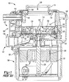
Fig. 1 depicts a prior art food waste disposer 100 which is similar to the prior art food waste disposer described inUS 7,360,729 . The disposer includes an upperfood conveying section 102, acentral grinding section 104 and amotor section 106, which may include a variable speed motor. It should be understood thatmotor section 106 could also include a fixed speed motor, such as an induction motor. Thegrinding section 104 is disposed between thefood conveying section 102 and themotor section 106. - The
food conveying section 102 conveys the food waste to thegrinding section 104. Thefood conveying section 102 includes aninlet housing 108 and a conveyinghousing 110. Theinlet housing 108 has aninlet 109 at the upper end of the food waste disposer 100 for receiving food waste and water.Inlet 109 is surrounded by agasket 111. Theinlet housing 108 is attached to the conveyinghousing 110, such as by anantivibration mount 113. - The conveying
housing 110 has an opening 142 to receive adishwasher inlet 144. The dishwasher inlet is used to pass water from a dishwasher (not shown). The inlet housing 108 and conveyinghousing 110 may be made of metal or molded plastic. Alternatively,inlet housing 108 and conveyinghousing 110 may be one unitary piece. - The
grinding section 104 includes ahousing 112 surrounding agrinding mechanism 114 having a rotatingshredder plate assembly 116 and astationary grind ring 118.Housing 112 is formed as a clamp ring andclamps conveying housing 110 to anupper end bell 136 ofmotor section 106.Stationary grind ring 118, which includes a plurality of spaced teeth 120 (only two of which are indicated byreference number 120 inFig. 1 ), may be received in anadaptor ring 122 disposed betweenhousing 112 andstationary grind ring 118. Agasket 123 is disposed betweenadaptor ring 122 and anupper portion 125 ofhousing 112. Abottom flange 127 of conveyinghousing 110 is received ingasket 123 and gasket 123 seals inlethousing 110 toadaptor ring 122. - The
shredder plate assembly 116 may include a rotatingshredder plate 124 mounted to arotatable shaft 126 of amotor 128 ofmotor section 106, such as by abolt 130.Motor 128 also includes arotor 129 to whichrotatable shaft 126 is affixed and astator 131. A plurality of fixed lugs 132 (only one of which is shown inFig. 1 ) are mounted on rotatingshredder plate 124 as are a plurality of swivel lugs 134 (only one of which is shown inFig. 1 ). It should be understood that in this regard, rotatingshredder plate assembly 116 could include only fixedlugs 132 or onlyswivel lugs 134. -
Motor section 106 includes anupper end bell 136 affixed to abottom 138 ofgrinding section 104.Upper end bell 136 includes adischarge chamber 140 having adischarge outlet 141 for coupling to a tailpipe or drainpipe (not shown). - In an aspect, food waste disposer 100 may include a
trim shell 146 that surroundsfood conveying section 102,grinding section 104 andmotor section 106. A layer ofsound insulation 148 may be disposed betweentrim shell 146 and conveyinghousing 110 offood conveying section 102 andhousing 112 ofgrinding section 104. - In the operation of the food waste disposer 100, the food waste delivered by the
food conveying section 102 to thegrinding section 104 is forced bylugs shredder plate assembly 116 againstteeth 120 of thestationary grind ring 118. The sharp edges of theteeth 120 grind or comminute the food waste into particulate matter that combines with water, such as water that entered the food waste disposer throughinlet 109, to form a slurry that drops intodischarge chamber 140. This slurry is then discharged through the discharge outlet (not shown) into the tailpipe or drainpipe (not shown). - The food conveying section 102 (which includes inlet
housing 108 and conveying housing 110) serves as the conduit for the food waste from the drain opening of the sink to the grinding mechanism of the grinding section. In a food waste disposer that operates in a batch feed mode, the amount of food waste that can be ground at a time is dictated by the volume of the food conveying section, mainly the conveyinghousing 110. - As discussed, conveying housings such as conveying
housing 110 can be made of different materials. The most common are a molded reinforced polymer such as glass filled polypropylene, or stainless steel. The advantages of stainless steel are higher durability and higher perceived consumer value. The primary disadvantage of stainless steel compared to a polymer is that is more difficult to form complex shapes of stainless steel compared to a polymer. - The shape of the conveying
housing 110 has an influence on the performance of the grinding mechanism. It is known in the art that a conveying housing with a conical or curved wall will redirect food waste expelled upwardly by the grinding mechanism back into the grinding mechanism more quickly than a housing with a straight wall. It is relatively easy to form a conveying housing having a conical or curved wall if molding a polymer to form the conveying housing. It is more difficult to do so if forming the conveying housing from stainless steel. - Typically, conveying housings made of stainless steel have been formed primarily as straight wall tubes. In certain prior art food waste disposers including one marketed under the InSinkErator® brand as Model 555, the food conveying housing was formed as a stainless steel tube where the lower portion of the stainless steel tube which contained the stationary shredder ring was expanded to a slightly larger diameter than the upper portion. This created a small shoulder over the stationary shredder ring which served as a food deflecting feature. In another prior art food waste disposer disclosed in
US 7,360,729 , the food conveying housing was formed as a stainless steel tube with a flange on the lower end. The stationary shredder ring was contained in a plastic adaptor ring that extended above the stationary shredder ring and incorporated a food deflecting overhang and bevel. The adaptor assembly and stainless steel tube were mated through a gasket and an external clamp ring.US 7,607,599 discloses a food waste reduction mechanism for a food waste disposer that has a ledge that overhangs a periphery of a rotating shredder plate assembly of the grinding mechanism of a food waste disposer. - In a prior art food waste disposer marketed under the InSinkErator® brand as Model 77, the conveying housing, which was made of stainless steel, had a two-chamber body in which the upper portion or chamber had a significantly smaller diameter than the lower portion or chamber. The transition between the small diameter upper portion and the larger diameter lower portion had a curved or arch-like profile that served to deflect food back into the grinding mechanism. The food waste disposer having this food conveying housing was a highly-aggressive, fast grinding food waste disposer compared to food waste disposers where the body of the food conveying housing was a straight wall stainless steel tube. The disadvantage of the food conveying housing having this two-chamber body was that the volume of the food conveying housing was reduced compared to straight wall bodies. Also, certain components such as the body top and trim shells had to be redesigned to accommodate the smaller diameter upper chamber.
- This section provides a general summary of the disclosure, and is not a comprehensive disclosure of its full scope, that is defined by the appended claims.
- In accordance with the invention of the present disclosure, a food waste disposer comprises the features of claim 1. The food waste disposer has a food conveying section that receives food waste and water; a grinding section including a grinding mechanism, and a motor section including a motor. The grinding section is disposed between the food conveying section and the motor section. The grinding mechanism includes a stationary grind ring and a rotating shredder plate assembly that rotates in the grind ring to grind food waste to form ground matter that combines with the water to form a slurry. The slurry passes into a discharge area in an upper end bell below the shredder plate assembly. The food conveying section includes a housing having a food waste deflecting band with an angular profile at a lower end of the housing.
- In an aspect, the food waste deflecting band includes diverters.
- In an aspect, the diverters are projections that project downwardly from a lower sloped wall of the food waste deflecting band. In an aspect, the diverters are projections that project inwardly from a junction where upper and lower sloped walls of the food waste deflecting band meet.
- In an aspect, the food deflecting band is discontinuous having a plurality of discontinuities spaced therearound which provide the diverters. In an aspect, the discontinuities are flattened sections of the food waste deflecting band wherein the lower sloped wall of the food waste deflecting band at each flattened section is flattened to provide a horizontally inwardly extending projection.
- In an aspect, the food waste deflecting band is a continuous band.
- In an aspect, the conveying housing is a conical wall housing and in an aspect, may be a plastic molded housing having the deflecting band integrally molded at a lower end thereof. In an aspect the deflecting band includes a plurality of diverters and in an aspect, each diverter includes a projection having a inwardly extending truncated triangular section and a downwardly extending truncated triangular section.
- Further areas of applicability will become apparent from the description provided herein. The description and specific examples in this summary are intended for purposes of illustration only and are not intended to limit the scope of the present disclosure, that is defined by the appended claims.
-
US2879949 - GIVEN MACHINERY COMPANY - Discloses a food waste disposer according to the preamble of claim 1 and relates to a means for the disposal of waste, more particularly household culinary waste or garbage, the invention involving the grinder type of disposal apparatus. -
US3236462 - FMC CORPORATION - Relates to waste disposal units, and more particularly, to an improved disposer for comminuting food waste the size and type found in restaurant kitchens. -
US3455518 - ATOMIC DISPOSER CORP - A disposer including a metal body having a vertical hole defining an inner wall carrying a circular array of inwardly projecting spaced teeth each defining a plurality of shearing edges. A disc is supported centrally in the vertical hole and rigidly carries a cutter means for consecutively cooperating with said plurality of shearing edges upon turning of the disc. - The present invention is set out in the independent claim 1 with some optional features set out in the claims dependent thereto.
- The drawings described herein are for illustrative purposes only of selected embodiments and not all possible implementations, and are not intended to limit the scope of the present disclosure, that is defined by the appended claims.
-
Fig. 1 shows a cross-sectional view of a prior art food waste disposer; -
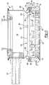
Fig. 2 shows a cross-sectional view of a food waste disposer having a food conveying housing having a straight cylindrical sidewall and a food waste deflecting band in a lower end thereof in accordance with an aspect of the present disclosure; -
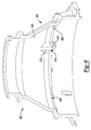
Fig. 3 is a cross-sectional perspective view of an upper portion of the food waste disposer ofFig. 2 ; -
Fig. 4 is a cross-sectional view cross-sectional perspective view of an alternative upper portion for the food waste disposer ofFig. 2 having a discontinuous food waste deflecting band in accordance with an aspect of the present disclosure; -
Fig. 5 is a bottom perspective view of the upper portion ofFig. 4 ; and -
Fig. 6 is a cross-section perspective view of an upper portion of a non-claimed food waste disposer having a food conveying section with a housing having a conical sidewall and a food deflecting band in a lower end thereof. - Example embodiments will now be described more fully with reference to the accompanying drawings. Corresponding reference numerals indicate corresponding parts throughout the several views of the drawings.
- With reference to
Fig. 2 , in accordance with an aspect of the present disclosure, afood waste disposer 200 is shown where alower end 204 of conveyinghousing 110' has afood deflecting band 202. Other than these differences,food waste disposer 200 is essentially the same asfood waste disposer 100. The following discussion will thus focus on these differences which relate to conveyinghousing 110' of food conveying section 102' havingfood deflecting band 202. Conveyinghousing 110' may illustratively be a cylinder, such as a stainless steel tube, with food deflecting band atlower end 204. -
Fig. 3 is a cross-sectional perspective view of food conveying section 102' and grindingsection 104, and shows in more detailfood deflecting band 202 at thelower end 204 of conveyinghousing 110'.Food deflecting band 202 extends around conveyinghousing 110' atlower end 204 thereof.Food deflecting band 202 includes abottom flange 206, a lower slopedwall 208 and an uppersloped wall 210, according to the invention.Bottom flange 206 extends overtops stationary grind ring 118 andadaptor ring 122.Bottom flange 206 is captured between the tops 212, 213, respectively ofstationary grind ring 118 and adaptor 122 (on the one hand) andgasket 123 abuttingupper portion 125 of grindingsection housing 112 on the other hand. In the illustrative embodiment shown inFigs. 2 and3 , foodwaste deflecting band 202 is a continuous band extending around conveyinghousing 202. It should be understood that foodwaste deflecting band 202 may be discontinuous as discussed in more detail below. - In the embodiment shown in
Figs. 2 - 4 , lower slopedwall 208 is planar and has a slope that slopes frombottom flange 206 at an angle inwardly and upwardly, according to the invention. The angle is an angle at which food waste expelled upwardly by rotatingshredder plate assembly 116 from generally the periphery thereof is deflected back down into the grindingsection 104. It may illustratively be determined heuristically. It may, by way of example and not of limitation, be forty-five degrees. It should be understood that lower slopedwall 208 can have a shape that is other than planar. Its shape could for example be concave, convex or have other curvatures. - Lower
sloped wall 208 and uppersloped wall 210 meet at ajunction 214, which is at radially inner ends of each of lower slopedwall 208 and uppersloped wall 210, according to the invention. In this regard,reference number 214 also identifies the radially inner ends of lower slopedwall 208 and uppersloped wall 210. - Upper
sloped wall 210 extends betweenjunction 214 and straightcylindrical sidewall 216 of conveyinghousing 110'. In the example of the invention shown inFigs. 2 and3 ,upper wall 210 slopes upwardly and outwardly fromjunction 214 tocylindrical sidewall 216.Upper wall 210 may, for example, slope at the same angle as lowersloped wall 208. In this illustrative example,food deflecting band 202 is a V-shaped band with the point of the V,junction 214, the radially innermost part offood deflecting band 202. It should be understood, thatupper wall 210 could slope at an angle other than the angle at which lower slopedwall 208 slopes, or a non-claimed embodiment could extend horizontally betweenjunction 214 andcylindrical sidewall 216. - In operation when
shredder plate assembly 116 is rotating, food waste that is expelled upwardly from grindingsection 104 is reflected by foodwaste deflecting band 202 back to grindingmechanism 114 in grindingsection 104. It should be understood that some of the food waste that is expelled upwardly from grindingsection 104 may be expelled inwardly as well, and thus may not be reflected by foodwaste deflecting band 202. However, the expulsion of food waste upwardly from grindingsection 104 is typically caused by the contact of the food waste againststationary grind ring 118 and thus it is expelled upwardly from a periphery ofrotating shredder plate 124, such as alongstationary grind ring 118. This food waste is thus likely to contact foodwaste deflecting band 202 and be reflected back into grindingsection 104. -
Food deflecting band 202 may optionally includediverters 220.Diverters 220 prevent food waste from riding onfood deflecting band 202, particularly lower slopedwall 208, and helps it more rapidly tumble back into grindingsection 104. "Riding" as that term is used in the art is where food waste spins but does not grind. In an aspect, diverters 220 may illustratively be projections that project downwardly from lower slopedwall 208 and may be formed in lower slopedwall 208, such as dimples, truncated triangular members, or other projecting members.Diverters 220 may alternatively be members attached to lower slopedwall 208. In an illustrative aspect, lower slopedwall 208 includes threediverters 220 spaced equidistantly aroundfood deflecting band 202. It should be understood thatfood deflecting band 202 can have more or fewer than threediverters 220, or none at all. It should also be understood thatdiverters 220 could additionally or alternatively be projections that project inwardly fromjunction 214, such asprojection 300 shown inFig. 3 .Diverters 220 could be integrally formed as part offood deflecting band 202, or be affixed tofood deflecting band 202.Diverters 220 could by way of example and not of limitation when conveyinghousing 110' is a molded plastic housing, be integrally molded with conveyinghousing 110', and in an aspect, may be a metal cladded.Diverters 220 could also be, by way of example and not of limitation, stamped or cast metal parts, molded plastic parts, or metal reinforced molded plastic parts. - In an aspect, the food waste deflecting band may be discontinuous with the
diverters 220 being provided by discontinuities in the food waste deflecting band.Fig. 4 is a cross-sectional perspective view of afood conveying section 400 having a discontinuousfood deflecting band 402 andFig. 5 is a bottom view of food conveying section 400 (but withoutdishwasher inlet 144 being shown).Food conveying section 400 is the same as food conveying section 102' other than discontinuousfood deflecting band 402. Discontinuous foodwaste deflecting band 402 has a plurality ofdiscontinuities 404 therein spaced aroundfood deflecting band 402, only one of which is shown inFig. 4 . In the aspect shown inFigs. 4 and5 , eachdiscontinuity 400 is a flattenedsection 408 of the foodwaste deflecting band 402 that in an aspect, is formed by anindentation 410 inupper wall 210 and a corresponding inwardly extendinghorizontal projection 412 in lower slopedwall 208 immediately beneathindentation 410. The term "horizontal" is used in this context with reference to the orientation ofprojection 412 whenfood waste disposer 200 is mounted to a sink. In this regard,horizontal projection 412 may in effect be an inward extension or projection ofbottom flange 206. It should be understood thathorizontal projection 412 can have a slight angle with respect to horizontal and the term horizontal projection in this context includes a projection that has a slight angle with respect to horizontal as well as a projection that is horizontal. Discontinuousfood deflecting band 402 may in an aspect have threediscontinuities 404 and may in an aspect have fourdiscontinuities 404. It should be understood that discontinuousfood deflecting band 402 may have other than three or fourdiscontinuities 404. Eachdiscontinuity 404 may be 5/8 of 2.54 cm (an inch) wide. It should be understood however, that eachdiscontinuity 404 may have a width other than 5/8 of 2.54 cm (an inch). In an aspect, discontinuous foodwaste deflecting band 402 may also include projections that providediverters 220 in addition todiscontinuities 404. - In the illustrative embodiments shown in
Figs. 2 - 5 , conveyinghousing 110' is formed of stainless steel andfood deflecting band 202, 202' formed as an integral part thereof. It should be understood thatfood conveying housing 110' could also be die cast metal (such as aluminum, magnesium, zinc or other die castable metals) or molded of plastic. It should also be understood thatfood deflecting band cylindrical sidewall 216 offood conveying housing 110' at a bottom thereof. - While conveying
housing 110' in the embodiment shown inFigs. 2 and4 has a straight, verticalcylindrical sidewall 216, it should be understood that the conveying housing could have a conical or curved sidewall. The term "vertical" is used in this context with reference to the orientation ofsidewall 216 whenfood waste disposer 200 is mounted to a sink.Fig. 6 shows a sectional view offood conveying section 600 having a conveyinghousing 602 having aconical sidewall 604 with foodwaste deflecting band 606 extending therearound at alower end 608 ofconical sidewall 604. Foodwaste deflecting band 606 may optionally includediverters 610 spaced around it (only one of which is shown inFig. 6 )Diverters 610 in the embodiment shown inFig. 6 have an inwardly projecting truncatedtriangular section 612 and a downwardly projecting truncatedtriangular section 614. In should be understood thatdiverters 610 can have other shapes. - Spatially relative terms, such as "inner," "outer," "beneath," "below," "lower," "above," "upper," and the like, may be used herein for ease of description to describe one element or feature's relationship to another element(s) or feature(s) as illustrated in the figures. Spatially relative terms may be intended to encompass different orientations of the device in use or operation in addition to the orientation depicted in the figures. For example, if the device in the figures is turned over, elements described as "below" or "beneath" other elements or features would then be oriented "above" the other elements or features. Thus, the example term "below" can encompass both an orientation of above and below. The device may be otherwise oriented (rotated 90 degrees or at other orientations) and the spatially relative descriptors used herein interpreted accordingly.
- The foregoing description of the embodiments has been provided for purposes of illustration and description. It is not intended to be exhaustive or to limit the disclosure. Individual elements or features of a particular embodiment are generally not limited to that particular embodiment, but, where applicable, are interchangeable and can be used in a selected embodiment, even if not specifically shown or described. The same may also be varied in many ways. Such variations are not to be regarded as a departure from the disclosure, and all such modifications are intended to be included within the scope of the disclosure, that is defined by the appended claims.
Claims (12)
- A food waste disposer (200), comprising:a food conveying section (102')that receives food waste and water;a motor section (106) including a motor (128);a grinding section (104) disposed between the food conveying section (102') and the motor section (106), the grinding section (104) including a grinding mechanism (114), the grinding mechanism (114) including a stationary grind ring (118) and a rotating shredder plate assembly (116) that rotates in the stationary grind ring (118); andthe food conveying section (102', 400, 600) including a housing (110', 602) having a food waste deflecting band (202, 402, 606) at a lower end (204) of the housing (110', 602) that extends inwardly from the housing (110') above the stationary grind ring (118), the food waste deflecting band (202, 402, 606) having an angular profile with a lower sloped wall (208) that slopes upwardly and inwardly; wherein the lower sloped wall (208) of the food waste deflecting band (202, 402, 606) slopes upwardly and inwardly from a bottom flange (206) of the food waste deflecting band (202, 402, 606);characterised in that the food waste deflecting band (202, 402, 606) includes an upper sloped wall (210), the upper and lower sloped walls (210, 208) meeting at a junction (214) of radially inner ends (214) thereof, the upper sloped wall (210) sloping upwardly and outwardly from the junction (214) where it meets the lower sloped wall (208).
- The food waste disposer of claim 1, wherein the food waste deflecting band (202, 402, 606) includes a plurality of diverters (220, 404, 610).
- The food waste disposer of claim 2 wherein the diverters (220, 610) are projections that project downwardly from the lower sloped wall (208) of the food waste deflecting band (202, 606).
- The food waste disposer of claim 2 wherein the diverters (220) are projections (300) that project inwardly from a junction (214) where upper and lower sloped walls (210, 208) of the food waste deflecting band (202) meet.
- The food waste disposer of claim 2 wherein the diverters (220) are discontinuities (404) in the food waste deflecting band (402).
- The food waste disposer of claim 5 wherein the discontinuities (404) are flattened sections (408) of the food waste deflecting band (402) wherein the lower sloped wall (208) of the food waste deflecting band at each flattened section (408) is flattened to provide a horizontally inwardly extending projection (412).
- The food waste disposer of claim 1 wherein the food waste deflecting band (202) is a continuous food waste deflecting band.
- The food waste disposer of claim 1 wherein the housing (110') of the food conveying section (102') is cylindrical.
- The food waste disposer of claim 1 wherein the housing (110') of the food conveying section (102') is conical.
- The food waste disposer of claim 9 wherein the food waste deflecting band (202) includes a plurality of diverters (220).
- The food waste disposer of claim 2 wherein each diverter (610) includes a projection having a inwardly extending truncated triangular section (612) and a downwardly extending truncated triangular section (614).
- The food waste disposer of claim 11 wherein the bottom flange (206) extends over tops (212, 213) of the stationary grind ring (118) and an adaptor ring (122) in which the stationary grind ring (118) is received.
Applications Claiming Priority (3)
| Application Number | Priority Date | Filing Date | Title |
|---|---|---|---|
| US201161505558P | 2011-07-08 | 2011-07-08 | |
| PCT/US2012/045659 WO2013009590A1 (en) | 2011-07-08 | 2012-07-06 | Food waste disposer with food deflecting housing |
| US13/542,758 US8985489B2 (en) | 2011-07-08 | 2012-07-06 | Food waste disposer with food deflecting housing |
Publications (2)
| Publication Number | Publication Date |
|---|---|
| EP2729630A1 EP2729630A1 (en) | 2014-05-14 |
| EP2729630B1 true EP2729630B1 (en) | 2016-11-30 |
Family
ID=46548845
Family Applications (1)
| Application Number | Title | Priority Date | Filing Date |
|---|---|---|---|
| EP12737969.1A Not-in-force EP2729630B1 (en) | 2011-07-08 | 2012-07-06 | Food waste disposer with food deflecting housing |
Country Status (6)
| Country | Link |
|---|---|
| US (1) | US8985489B2 (en) |
| EP (1) | EP2729630B1 (en) |
| JP (1) | JP3191841U (en) |
| CN (1) | CN203846580U (en) |
| ES (1) | ES2613817T3 (en) |
| WO (1) | WO2013009590A1 (en) |
Families Citing this family (11)
| Publication number | Priority date | Publication date | Assignee | Title |
|---|---|---|---|---|
| US9222246B2 (en) * | 2013-10-28 | 2015-12-29 | General Electric Company | Waste disposal with enhanced water management features |
| US9752307B2 (en) * | 2014-03-24 | 2017-09-05 | Haier Us Appliance Solutions, Inc. | Disposal assembly and method for operating same |
| CN105195275B (en) * | 2015-10-14 | 2018-08-10 | 珠海格力电器股份有限公司 | Grinding ring for garbage disposer and garbage disposer |
| US11161123B2 (en) * | 2018-11-30 | 2021-11-02 | Emerson Electric Co. | Food waste disposer monitoring using phase difference between motor voltage and motor current |
| US11280075B2 (en) | 2019-01-29 | 2022-03-22 | Fb Global Plumbing Group Llc | Disposal with above sink installation |
| CN110665608A (en) * | 2019-11-12 | 2020-01-10 | 广东杰美科技有限公司 | Fixed knife wall and food waste disposer |
| WO2021138729A1 (en) * | 2020-01-06 | 2021-07-15 | Anvy Technologies Inc. | Organic waste separator for under a sink |
| CN114054175B (en) * | 2020-07-29 | 2022-11-29 | 宁波方太厨具有限公司 | Kitchen garbage disposer |
| CN112156867B (en) * | 2020-09-09 | 2021-12-24 | 山东交通学院 | An anti-blocking distribution device with secondary cutting and crushing functions |
| KR102474087B1 (en) * | 2020-12-07 | 2022-12-05 | 김종훈 | Food waste disposal device |
| BR112023016933A2 (en) * | 2021-02-26 | 2023-11-07 | Emerson Electric Co | FOOD WASTE CRUSHER AND CRUSHING MECHANISM FOR A FOOD WASTE CRUSHER |
Family Cites Families (14)
| Publication number | Priority date | Publication date | Assignee | Title |
|---|---|---|---|---|
| US2879949A (en) * | 1954-12-03 | 1959-03-31 | Given Machinery Company | Garbage disposal apparatus |
| US3013736A (en) * | 1958-02-26 | 1961-12-19 | Gen Motors Corp | Domestic appliance |
| US3025007A (en) | 1960-05-19 | 1962-03-13 | In Sink Erator Mfg Company | Disposal unit |
| US3236462A (en) | 1962-10-26 | 1966-02-22 | Fmc Corp | Waste disposer |
| US3188012A (en) * | 1963-02-04 | 1965-06-08 | Gen Electric | Impeller designs for food waste disposer |
| US3455518A (en) * | 1965-08-04 | 1969-07-15 | Atomic Disposer Corp | Cutting assembly and element for disposers |
| US3464368A (en) | 1967-11-08 | 1969-09-02 | Acf Ind Inc | Foldable bulkhead for a railroad flatcar |
| US3875462A (en) * | 1973-02-01 | 1975-04-01 | Gen Electric | Food waste disposer |
| US6007006A (en) | 1998-07-23 | 1999-12-28 | Emerson Electric Co. | Food waste disposer |
| US6481652B2 (en) * | 2000-11-28 | 2002-11-19 | Emerson Electric Co. | Food waste disposer having variable speed motor and methods of operating same |
| US7607599B2 (en) | 2003-06-06 | 2009-10-27 | Emerson Electric Co. | Food waste reduction mechanism for disposer |
| US7578460B2 (en) * | 2003-06-17 | 2009-08-25 | Emerson Electric Co. | Food waste disposer having antimicrobial components |
| US7360729B2 (en) | 2004-04-26 | 2008-04-22 | Emerson Electric Co. | Food waste disposer shredder assembly |
| US8220731B2 (en) * | 2009-05-20 | 2012-07-17 | Emerson Electric Co. | Food waste disposer and threaded mount system |
-
2012
- 2012-07-06 CN CN201290000656.8U patent/CN203846580U/en not_active Expired - Lifetime
- 2012-07-06 ES ES12737969.1T patent/ES2613817T3/en active Active
- 2012-07-06 EP EP12737969.1A patent/EP2729630B1/en not_active Not-in-force
- 2012-07-06 JP JP2014600028U patent/JP3191841U/en not_active Expired - Lifetime
- 2012-07-06 WO PCT/US2012/045659 patent/WO2013009590A1/en not_active Ceased
- 2012-07-06 US US13/542,758 patent/US8985489B2/en active Active
Non-Patent Citations (1)
| Title |
|---|
| None * |
Also Published As
| Publication number | Publication date |
|---|---|
| ES2613817T3 (en) | 2017-05-26 |
| CN203846580U (en) | 2014-09-24 |
| EP2729630A1 (en) | 2014-05-14 |
| JP3191841U (en) | 2014-07-17 |
| WO2013009590A1 (en) | 2013-01-17 |
| US8985489B2 (en) | 2015-03-24 |
| US20130175375A1 (en) | 2013-07-11 |
Similar Documents
| Publication | Publication Date | Title |
|---|---|---|
| US8985489B2 (en) | Food waste disposer with food deflecting housing | |
| US8500050B2 (en) | Food waste disposer with restricted grind chamber discharge | |
| AU2014100576A4 (en) | Threaded sink flange assembly for installation of a food waste disposer to a sink | |
| EP1988223B1 (en) | Food waste disposal unit | |
| JP5019690B2 (en) | Crushing mechanism for food waste disposer | |
| EP2468967B1 (en) | Food waste disposer grinding mechanism | |
| US20080116305A1 (en) | Food Waste Disposer With Grinding Mechanism With Windowed Grind Ring | |
| AU2009202897A1 (en) | Waste food disposal unit | |
| EP1636436B1 (en) | Food waste reduction mechanism for disposer | |
| US9574334B2 (en) | Stationary cutter ring for waste disposals | |
| CN113145275B (en) | Food waste multi-stage grinding structure and food waste disposer | |
| US20130015277A1 (en) | Food waste disposer with pumping vane | |
| AU2011100575A4 (en) | Battery powered food waste disposer | |
| WO2020034852A1 (en) | Rotating cutter disc | |
| EP1770226A2 (en) | Waste food disposal unit | |
| US3439878A (en) | Impeller for food waste disposer | |
| AU2014100112A4 (en) | Food waste disposer with food deflecting housing | |
| CN203184086U (en) | Food waste treatment device | |
| CN110528642A (en) | Garbage disposer | |
| US20140319252A1 (en) | Food Waste Disposer With Stamped Swivel Lugs | |
| JP7720557B2 (en) | disposer | |
| CN2226977Y (en) | Treater of food waste | |
| AU2011101665A4 (en) | Food waste disposer and mount system | |
| AU2013101022A4 (en) | Food waste disposer with pumping vane | |
| CN204147963U (en) | A kind of food refuse disposer |
Legal Events
| Date | Code | Title | Description |
|---|---|---|---|
| PUAI | Public reference made under article 153(3) epc to a published international application that has entered the european phase |
Free format text: ORIGINAL CODE: 0009012 |
|
| 17P | Request for examination filed |
Effective date: 20140129 |
|
| AK | Designated contracting states |
Kind code of ref document: A1 Designated state(s): AL AT BE BG CH CY CZ DE DK EE ES FI FR GB GR HR HU IE IS IT LI LT LU LV MC MK MT NL NO PL PT RO RS SE SI SK SM TR |
|
| DAX | Request for extension of the european patent (deleted) | ||
| 17Q | First examination report despatched |
Effective date: 20160226 |
|
| GRAP | Despatch of communication of intention to grant a patent |
Free format text: ORIGINAL CODE: EPIDOSNIGR1 |
|
| INTG | Intention to grant announced |
Effective date: 20160721 |
|
| GRAS | Grant fee paid |
Free format text: ORIGINAL CODE: EPIDOSNIGR3 |
|
| GRAA | (expected) grant |
Free format text: ORIGINAL CODE: 0009210 |
|
| AK | Designated contracting states |
Kind code of ref document: B1 Designated state(s): AL AT BE BG CH CY CZ DE DK EE ES FI FR GB GR HR HU IE IS IT LI LT LU LV MC MK MT NL NO PL PT RO RS SE SI SK SM TR |
|
| REG | Reference to a national code |
Ref country code: CH Ref legal event code: EP Ref country code: GB Ref legal event code: FG4D |
|
| REG | Reference to a national code |
Ref country code: AT Ref legal event code: REF Ref document number: 849937 Country of ref document: AT Kind code of ref document: T Effective date: 20161215 |
|
| REG | Reference to a national code |
Ref country code: IE Ref legal event code: FG4D |
|
| REG | Reference to a national code |
Ref country code: DE Ref legal event code: R096 Ref document number: 602012026039 Country of ref document: DE |
|
| PG25 | Lapsed in a contracting state [announced via postgrant information from national office to epo] |
Ref country code: LV Free format text: LAPSE BECAUSE OF FAILURE TO SUBMIT A TRANSLATION OF THE DESCRIPTION OR TO PAY THE FEE WITHIN THE PRESCRIBED TIME-LIMIT Effective date: 20161130 |
|
| REG | Reference to a national code |
Ref country code: LT Ref legal event code: MG4D |
|
| REG | Reference to a national code |
Ref country code: NL Ref legal event code: MP Effective date: 20161130 |
|
| REG | Reference to a national code |
Ref country code: AT Ref legal event code: MK05 Ref document number: 849937 Country of ref document: AT Kind code of ref document: T Effective date: 20161130 |
|
| PG25 | Lapsed in a contracting state [announced via postgrant information from national office to epo] |
Ref country code: GR Free format text: LAPSE BECAUSE OF FAILURE TO SUBMIT A TRANSLATION OF THE DESCRIPTION OR TO PAY THE FEE WITHIN THE PRESCRIBED TIME-LIMIT Effective date: 20170301 Ref country code: LT Free format text: LAPSE BECAUSE OF FAILURE TO SUBMIT A TRANSLATION OF THE DESCRIPTION OR TO PAY THE FEE WITHIN THE PRESCRIBED TIME-LIMIT Effective date: 20161130 Ref country code: NO Free format text: LAPSE BECAUSE OF FAILURE TO SUBMIT A TRANSLATION OF THE DESCRIPTION OR TO PAY THE FEE WITHIN THE PRESCRIBED TIME-LIMIT Effective date: 20170228 Ref country code: SE Free format text: LAPSE BECAUSE OF FAILURE TO SUBMIT A TRANSLATION OF THE DESCRIPTION OR TO PAY THE FEE WITHIN THE PRESCRIBED TIME-LIMIT Effective date: 20161130 |
|
| REG | Reference to a national code |
Ref country code: ES Ref legal event code: FG2A Ref document number: 2613817 Country of ref document: ES Kind code of ref document: T3 Effective date: 20170526 |
|
| PG25 | Lapsed in a contracting state [announced via postgrant information from national office to epo] |
Ref country code: AT Free format text: LAPSE BECAUSE OF FAILURE TO SUBMIT A TRANSLATION OF THE DESCRIPTION OR TO PAY THE FEE WITHIN THE PRESCRIBED TIME-LIMIT Effective date: 20161130 Ref country code: FI Free format text: LAPSE BECAUSE OF FAILURE TO SUBMIT A TRANSLATION OF THE DESCRIPTION OR TO PAY THE FEE WITHIN THE PRESCRIBED TIME-LIMIT Effective date: 20161130 Ref country code: RS Free format text: LAPSE BECAUSE OF FAILURE TO SUBMIT A TRANSLATION OF THE DESCRIPTION OR TO PAY THE FEE WITHIN THE PRESCRIBED TIME-LIMIT Effective date: 20161130 Ref country code: PT Free format text: LAPSE BECAUSE OF FAILURE TO SUBMIT A TRANSLATION OF THE DESCRIPTION OR TO PAY THE FEE WITHIN THE PRESCRIBED TIME-LIMIT Effective date: 20170330 Ref country code: PL Free format text: LAPSE BECAUSE OF FAILURE TO SUBMIT A TRANSLATION OF THE DESCRIPTION OR TO PAY THE FEE WITHIN THE PRESCRIBED TIME-LIMIT Effective date: 20161130 Ref country code: HR Free format text: LAPSE BECAUSE OF FAILURE TO SUBMIT A TRANSLATION OF THE DESCRIPTION OR TO PAY THE FEE WITHIN THE PRESCRIBED TIME-LIMIT Effective date: 20161130 |
|
| PG25 | Lapsed in a contracting state [announced via postgrant information from national office to epo] |
Ref country code: NL Free format text: LAPSE BECAUSE OF FAILURE TO SUBMIT A TRANSLATION OF THE DESCRIPTION OR TO PAY THE FEE WITHIN THE PRESCRIBED TIME-LIMIT Effective date: 20161130 |
|
| PG25 | Lapsed in a contracting state [announced via postgrant information from national office to epo] |
Ref country code: CZ Free format text: LAPSE BECAUSE OF FAILURE TO SUBMIT A TRANSLATION OF THE DESCRIPTION OR TO PAY THE FEE WITHIN THE PRESCRIBED TIME-LIMIT Effective date: 20161130 Ref country code: EE Free format text: LAPSE BECAUSE OF FAILURE TO SUBMIT A TRANSLATION OF THE DESCRIPTION OR TO PAY THE FEE WITHIN THE PRESCRIBED TIME-LIMIT Effective date: 20161130 Ref country code: SK Free format text: LAPSE BECAUSE OF FAILURE TO SUBMIT A TRANSLATION OF THE DESCRIPTION OR TO PAY THE FEE WITHIN THE PRESCRIBED TIME-LIMIT Effective date: 20161130 Ref country code: DK Free format text: LAPSE BECAUSE OF FAILURE TO SUBMIT A TRANSLATION OF THE DESCRIPTION OR TO PAY THE FEE WITHIN THE PRESCRIBED TIME-LIMIT Effective date: 20161130 Ref country code: RO Free format text: LAPSE BECAUSE OF FAILURE TO SUBMIT A TRANSLATION OF THE DESCRIPTION OR TO PAY THE FEE WITHIN THE PRESCRIBED TIME-LIMIT Effective date: 20161130 |
|
| PG25 | Lapsed in a contracting state [announced via postgrant information from national office to epo] |
Ref country code: BE Free format text: LAPSE BECAUSE OF FAILURE TO SUBMIT A TRANSLATION OF THE DESCRIPTION OR TO PAY THE FEE WITHIN THE PRESCRIBED TIME-LIMIT Effective date: 20161130 Ref country code: BG Free format text: LAPSE BECAUSE OF FAILURE TO SUBMIT A TRANSLATION OF THE DESCRIPTION OR TO PAY THE FEE WITHIN THE PRESCRIBED TIME-LIMIT Effective date: 20170228 Ref country code: SM Free format text: LAPSE BECAUSE OF FAILURE TO SUBMIT A TRANSLATION OF THE DESCRIPTION OR TO PAY THE FEE WITHIN THE PRESCRIBED TIME-LIMIT Effective date: 20161130 |
|
| REG | Reference to a national code |
Ref country code: DE Ref legal event code: R097 Ref document number: 602012026039 Country of ref document: DE |
|
| PLBE | No opposition filed within time limit |
Free format text: ORIGINAL CODE: 0009261 |
|
| STAA | Information on the status of an ep patent application or granted ep patent |
Free format text: STATUS: NO OPPOSITION FILED WITHIN TIME LIMIT |
|
| 26N | No opposition filed |
Effective date: 20170831 |
|
| PG25 | Lapsed in a contracting state [announced via postgrant information from national office to epo] |
Ref country code: SI Free format text: LAPSE BECAUSE OF FAILURE TO SUBMIT A TRANSLATION OF THE DESCRIPTION OR TO PAY THE FEE WITHIN THE PRESCRIBED TIME-LIMIT Effective date: 20161130 |
|
| REG | Reference to a national code |
Ref country code: DE Ref legal event code: R119 Ref document number: 602012026039 Country of ref document: DE |
|
| REG | Reference to a national code |
Ref country code: CH Ref legal event code: PL |
|
| REG | Reference to a national code |
Ref country code: IE Ref legal event code: MM4A |
|
| REG | Reference to a national code |
Ref country code: FR Ref legal event code: ST Effective date: 20180330 |
|
| PG25 | Lapsed in a contracting state [announced via postgrant information from national office to epo] |
Ref country code: CH Free format text: LAPSE BECAUSE OF NON-PAYMENT OF DUE FEES Effective date: 20170731 Ref country code: IE Free format text: LAPSE BECAUSE OF NON-PAYMENT OF DUE FEES Effective date: 20170706 Ref country code: LI Free format text: LAPSE BECAUSE OF NON-PAYMENT OF DUE FEES Effective date: 20170731 Ref country code: DE Free format text: LAPSE BECAUSE OF NON-PAYMENT OF DUE FEES Effective date: 20180201 |
|
| PG25 | Lapsed in a contracting state [announced via postgrant information from national office to epo] |
Ref country code: FR Free format text: LAPSE BECAUSE OF NON-PAYMENT OF DUE FEES Effective date: 20170731 |
|
| PG25 | Lapsed in a contracting state [announced via postgrant information from national office to epo] |
Ref country code: LU Free format text: LAPSE BECAUSE OF NON-PAYMENT OF DUE FEES Effective date: 20170706 |
|
| PG25 | Lapsed in a contracting state [announced via postgrant information from national office to epo] |
Ref country code: MT Free format text: LAPSE BECAUSE OF NON-PAYMENT OF DUE FEES Effective date: 20170706 |
|
| PG25 | Lapsed in a contracting state [announced via postgrant information from national office to epo] |
Ref country code: HU Free format text: LAPSE BECAUSE OF FAILURE TO SUBMIT A TRANSLATION OF THE DESCRIPTION OR TO PAY THE FEE WITHIN THE PRESCRIBED TIME-LIMIT; INVALID AB INITIO Effective date: 20120706 Ref country code: MC Free format text: LAPSE BECAUSE OF FAILURE TO SUBMIT A TRANSLATION OF THE DESCRIPTION OR TO PAY THE FEE WITHIN THE PRESCRIBED TIME-LIMIT Effective date: 20161130 |
|
| PG25 | Lapsed in a contracting state [announced via postgrant information from national office to epo] |
Ref country code: CY Free format text: LAPSE BECAUSE OF NON-PAYMENT OF DUE FEES Effective date: 20161130 |
|
| PG25 | Lapsed in a contracting state [announced via postgrant information from national office to epo] |
Ref country code: MK Free format text: LAPSE BECAUSE OF FAILURE TO SUBMIT A TRANSLATION OF THE DESCRIPTION OR TO PAY THE FEE WITHIN THE PRESCRIBED TIME-LIMIT Effective date: 20161130 |
|
| PG25 | Lapsed in a contracting state [announced via postgrant information from national office to epo] |
Ref country code: TR Free format text: LAPSE BECAUSE OF FAILURE TO SUBMIT A TRANSLATION OF THE DESCRIPTION OR TO PAY THE FEE WITHIN THE PRESCRIBED TIME-LIMIT Effective date: 20161130 |
|
| PG25 | Lapsed in a contracting state [announced via postgrant information from national office to epo] |
Ref country code: AL Free format text: LAPSE BECAUSE OF FAILURE TO SUBMIT A TRANSLATION OF THE DESCRIPTION OR TO PAY THE FEE WITHIN THE PRESCRIBED TIME-LIMIT Effective date: 20161130 Ref country code: IS Free format text: LAPSE BECAUSE OF FAILURE TO SUBMIT A TRANSLATION OF THE DESCRIPTION OR TO PAY THE FEE WITHIN THE PRESCRIBED TIME-LIMIT Effective date: 20170330 |
|
| PGFP | Annual fee paid to national office [announced via postgrant information from national office to epo] |
Ref country code: ES Payment date: 20200803 Year of fee payment: 9 |
|
| PGFP | Annual fee paid to national office [announced via postgrant information from national office to epo] |
Ref country code: IT Payment date: 20200622 Year of fee payment: 9 |
|
| PG25 | Lapsed in a contracting state [announced via postgrant information from national office to epo] |
Ref country code: IT Free format text: LAPSE BECAUSE OF NON-PAYMENT OF DUE FEES Effective date: 20210706 |
|
| REG | Reference to a national code |
Ref country code: ES Ref legal event code: FD2A Effective date: 20220926 |
|
| PG25 | Lapsed in a contracting state [announced via postgrant information from national office to epo] |
Ref country code: ES Free format text: LAPSE BECAUSE OF NON-PAYMENT OF DUE FEES Effective date: 20210707 |
|
| PGFP | Annual fee paid to national office [announced via postgrant information from national office to epo] |
Ref country code: GB Payment date: 20240724 Year of fee payment: 13 |
|
| GBPC | Gb: european patent ceased through non-payment of renewal fee |
Effective date: 20250706 |
|
| PG25 | Lapsed in a contracting state [announced via postgrant information from national office to epo] |
Ref country code: GB Free format text: LAPSE BECAUSE OF NON-PAYMENT OF DUE FEES Effective date: 20250706 |