EP2729400B1 - Endless cable winch - Google Patents
Endless cable winch Download PDFInfo
- Publication number
- EP2729400B1 EP2729400B1 EP12730581.1A EP12730581A EP2729400B1 EP 2729400 B1 EP2729400 B1 EP 2729400B1 EP 12730581 A EP12730581 A EP 12730581A EP 2729400 B1 EP2729400 B1 EP 2729400B1
- Authority
- EP
- European Patent Office
- Prior art keywords
- cable
- endless
- sensor
- winch according
- safety
- Prior art date
- Legal status (The legal status is an assumption and is not a legal conclusion. Google has not performed a legal analysis and makes no representation as to the accuracy of the status listed.)
- Active
Links
Images


Classifications
-
- B—PERFORMING OPERATIONS; TRANSPORTING
- B66—HOISTING; LIFTING; HAULING
- B66D—CAPSTANS; WINCHES; TACKLES, e.g. PULLEY BLOCKS; HOISTS
- B66D1/00—Rope, cable, or chain winding mechanisms; Capstans
- B66D1/54—Safety gear
-
- B—PERFORMING OPERATIONS; TRANSPORTING
- B66—HOISTING; LIFTING; HAULING
- B66D—CAPSTANS; WINCHES; TACKLES, e.g. PULLEY BLOCKS; HOISTS
- B66D1/00—Rope, cable, or chain winding mechanisms; Capstans
- B66D1/02—Driving gear
-
- B—PERFORMING OPERATIONS; TRANSPORTING
- B66—HOISTING; LIFTING; HAULING
- B66D—CAPSTANS; WINCHES; TACKLES, e.g. PULLEY BLOCKS; HOISTS
- B66D1/00—Rope, cable, or chain winding mechanisms; Capstans
- B66D1/54—Safety gear
- B66D1/58—Safety gear responsive to excess of load
-
- B—PERFORMING OPERATIONS; TRANSPORTING
- B66—HOISTING; LIFTING; HAULING
- B66D—CAPSTANS; WINCHES; TACKLES, e.g. PULLEY BLOCKS; HOISTS
- B66D1/00—Rope, cable, or chain winding mechanisms; Capstans
- B66D1/60—Rope, cable, or chain winding mechanisms; Capstans adapted for special purposes
- B66D1/74—Capstans
- B66D1/7415—Friction drives, e.g. pulleys, having a cable winding angle of less than 360 degrees
Definitions
- the invention relates to an endless cable winch, comprising a working cable, a driving cable pulley around at least a part of which the working cable is wrapped, a drive for driving the driving cable pulley, and further comprising an overload detection device for identifying an overload of the working cable.
- Endless cable winches of this type are widely used for transporting loads or people. Endless cable winches have, for safety reasons, an overload detection device which responds in the event of a certain exceedance of the rated load in order to shut off the endless cable winch and/or output a warning signal.
- the load acting on the working cable is measured indirectly by means of a spring-loaded roller, by virtue of the travel of the roller being monitored.
- the disadvantage of this principle is that the load acting on the working cable is influenced by the weight of the hanging-down strand of the working cable. As a result, the measurement result may deviate to a great extent in particular at relatively great heights, that is to say in the case of long hanging-down strands, and therefore an overload detection device based on this can be rather inaccurate.
- EP 0 363 800 A discloses an endless cable winch according to the preamble of claim 1.
- an endless cable winch according to claim 1, in the case of an endless cable winch of the type mentioned at the outset, in that the housing is mounted so as to be pivotable about a pivot axis, and in that a sensor for detecting a pivoting movement of the housing is provided.
- the housing is pivotably mounted at a first end, and is suspended at a second end on an elongation element.
- the elongation element may be a spring element, an elongation cable or the like.
- the senor is in the form of a travel sensor, elongation sensor, contact sensor, piezo sensor or magnetic sensor.
- the drive is shut off when the sensor responds.
- a warning signal may be output when the sensor responds.
- a safety cable is provided with a safety device which has a non-driven cable pulley, which is rotatably mounted in a housing and around at least a part of which the safety cable is wrapped, and also has an arresting device which is coupled via a brake to the cable pulley and which blocks, and brakes the safety cable by means of the brake, at a predetermined speed of the safety cable at least in one direction.
- the arresting device hereby blocks, and brakes the safety cable by means of the brake, when the predetermined speed is reached.
- the result during the catching of the safety cable by means of the safety device, is relatively gentle braking of the safety cable with a braking acceleration for example of the order of magnitude of approximately 2 g. This has the result that a low loading of the safety cable upon the response of the safety device is achieved. Also, the physical and psychological stress on the personnel located in the person lifting device which is moved by means of the endless cable winch is reduced in this way.
- the arresting device comprises a ratchet wheel which interacts with a pawl mounted on the housing, in such a way that the pawl latches into the ratchet wheel at a predetermined speed of the safety cable.
- an arresting device is provided which is highly robust and which is of simple and reliable design.
- the pawl has a first pawl arm and a second pawl arm, between which the pawl is pivotably mounted on the housing, wherein the pawl is preloaded against the ratchet wheel in such a way that the first pawl arm can move along the ratchet wheel up to a predetermined speed, and latches with its second pawl arm into the ratchet wheel if the predetermined speed is exceeded in the downward direction of the safety cable.
- the predetermined speed at which the blocking takes place can be finely metered by means of the preload of the pawl.
- the ratchet wheel and the cable pulley are rotatable about a common axis of rotation, and the ratchet wheel forms a friction brake with the cable pulley.
- the brake is in the form of a conical brake.
- the design of the brake as a conical brake yields a particularly effective braking action with a relatively small installation size.
- the friction brake comprises a first friction partner composed of a bronze alloy and a second friction partner composed of a steel alloy.
- the brake preferably has a cone angle of approximately 4° to 10°.
- a particularly expedient configuration of the brake can be attained in this way.
- a friction lining may be provided on at least one of the friction partners. It is then generally the case here that a larger cone angle is used, of approximately 10° to 40°, e.g. approximately 30°.
- the ratchet wheel has an external cone which is spring-loaded against an internal cone of the cable pulley.
- the ratchet wheel may be preloaded against the internal cone of the cable pulley for example by means of a plate spring, the preload of which is preferably adjustable.
- At least the working cable or the safety cable are wrapped around the driving cable pulley or the cable pulley with a wrap angle of less than 300°, preferably of approximately 260° to 280°, particularly preferably of approximately 270°.
- wrap angle is normally 360°
- a smaller wrap angle may also be adequate.
- a smaller wrap angle of in particular approximately 270° has space advantages, since it is hereby possible in certain cases to dispense with a diverting roller.
- the predetermined speed for the braking of the safety cable is preferably 20 to 40 metres/minute, preferably 25 to 35 metres/minute, preferably approximately 30 metres/minute.
- the driving cable pulley and the cable pulley are mounted in a common housing.
- both the winch and also the safety device are of compact construction in a common housing.
- the safety device prefferably be formed as a separate unit with the arresting device and the brake.
- the cable pulley has a biasing device for pressing the safety cable against the cable pulley.
- the driving cable pulley has a biasing device for pressing the working cable against the driving cable pulley.
- the biasing device may be for example a spring-loaded pressing roller.
- FIG. 1 shows a perspective view of the endless cable winch 10.
- the endless cable winch 10 comprises a winch 22 which moves a working cable 28 upwards or downwards such that a load located thereon, e.g. lift cage, moves upwards or downwards on the working cable 28.
- the winch 22 comprises a drive 24 with a motor and a gearbox, and also comprises a controller 26.
- the endless cable winch 10 also comprises a safety device 30 through which a safety cable 16 is guided. If, by contrast, the endless cable winch 10 is used merely for transporting materials, it is possible to dispense with the safety cable 16 and the safety device 30.
- the winch 22 and the safety device 30 are accommodated in a common housing 54.
- the endless cable winch 10 is designed for a certain rated load, for example 600 kg. To avoid overloading, or to avoid accidents in the event of overloading, the endless cable winch 10 has an overload detection device denoted as a whole by 11.
- the overload detection device 11 monitors the force acting on the working cable 28. If the rated load is exceeded, for example by 25%, the overload detection device 11 identifies an overload state. In this case, the drive is immediately stopped and a warning signal is output.
- Figures 2 and 3 show the endless cable winch 10 in a front view.
- the endless cable winch 10 is fastened to two beams 21, 23. Only the rear beam 23 is illustrated in Figure 2 , whereas Figure 3 shows the front beam 21 which faces toward the viewer.
- the housing 54 is held at a first end so as to be pivotable about a pivot axis 12. At the opposite, second end, the housing 54 is held on a spring 14 which is held with one end in a housing recess 17 and which is fastened with its other end to a beam on which the housing 54 is held.
- the spring acts on the housing 54 of the endless cable winch.
- a sensor 13 is fastened to the housing 54.
- a holder 15 comprises an adjusting screw 18 by means of which the value for the overload can be finely adjusted.
- the sensor 13 may for example be in the form of an electrical contact sensor which closes an electrical circuit when a contact-making end of the spring 14 makes contact.
- This sensor could therefore for example also be a travel sensor in the form of a strain gauge or the like.
- the housing 54 has pivoted by a certain pivot angle as a result of the force acting on the working cable.
- the spring characteristic and the sensor are preferably coordinated with one another such that the sensor 13 responds when 125 % of the rated load of the endless cable winch 10 is reached, that is to say at 750 kg in the case of a rated load of 600 kg. This corresponds to the EN1808 standard.
- the drive is automatically stopped and a warning signal, for example a visual warning signal and an acoustic warning signal, is output. Furthermore, the overload state may be transmitted electrically to further elements via a signal line. Since the overload generally occurs when the endless cable winch 10 is at a standstill, the drive cannot start in this case, and, as a result of the warning signal output, a user will generally immediately recognize the overload, such that he can correspondingly reduce the load.
- a warning signal for example a visual warning signal and an acoustic warning signal
- the winch 22 has a driving cable pulley 58 over which the working cable 28 is guided with a wrap angle of approximately 270°.
- the driving cable pulley 58 has a guide groove 59 in which the working cable 28 runs.
- a biasing device 56 is also provided for biasing or pressing the working cable 28 into the guide groove 59. This biasing device involves a pressing roller combined with a spring.
- the working cable 28 emerges laterally out of the winch 22, as can be seen from Figure 1, after a wrap angle of approximately 270°, and can optionally then be diverted downwards by means of a diverting roller.
- Figure 4 also shows the drive 24 which comprises an electric motor and a gearbox.
- the output shaft 70 of the gearbox drives the driving cable pulley 58 via a shaft-type pinion (not illustrated).
- both the driving cable pulley 58 and also the cable pulley 68 are each mounted in the common housing 54 of the winch 22 and of the safety device 30 by means of two bearings 60, 62, 64, 66.
- the safety device 30 comprises an arresting device 31, the safety device being coupled by means of a brake, denoted as a whole by numeral 71, to a cable pulley 68 over which the safety cable 16 is guided. If the arresting device 31 arrests the safety cable 16 when a certain speed is reached, the cable pulley 68 is braked via the brake 71.
- the arresting device 31 comprises a rotatably mounted ratchet wheel 32, which interacts with a pawl 34 which is pivotably mounted on the housing 54.
- the ratchet wheel 32 has an external cone 72 which bears against an internal cone 74 of the cable pulley 68.
- the ratchet wheel 32 is preloaded against the cable pulley 68 by means of a plate spring 78 which is supported against a bearing ring 76 on a journal 73 of the cable pulley, such that there is frictional engagement between the external cone 72 of the ratchet wheel 32 and the internal cone 74 of the cable pulley 68.
- the preload of the plate spring 78 can be adjusted by means of a nut 82 which is screwed onto a thread 80 on the journal 73.
- a biasing device 48 consisting of spring and pressing roller, is also provided for the cable pulley 68, for pressing the safety cable 16 into the guide groove provided therefor.
- FIG. 5 shows in more detail the construction of the arresting device 31 which is part of the safety device 30.
- the pawl 34 is held so as to be pivotable about a pivot axis 36.
- the pawl 34 has a first pawl arm 38 and a second pawl arm 40 which protrude in opposite directions from the pivot axis 36.
- the pawl 34 is preloaded by a spring 46, which is accommodated on a holder 44, in such a way that the first pawl arm 38 normally bears against the internal toothing of the ratchet wheel 32. In this position, the ratchet wheel can be moved both clockwise and also anticlockwise without the pawl leading to blocking against the ratchet wheel 32.
- a load accommodated on the endless cable winch 10 for instance a lift cage, moves downwards.
- the pawl 34 runs with its first pawl arm 38 on the toothed inner surface of the ratchet wheel 32.
- the stress of the spring 46 is now set such that, when the downward speed of the safety cable 16 reaches approximately 30 metres per minute, the interaction of the first pawl arm 38 with the toothed inner surface of the ratchet wheel 32 causes the pawl 34 to lift from the inner surface of the ratchet wheel 32 and turn over, such that the pawl latches with a latching lug 42 at the end of the second pawl arm into the inner surface of the ratchet wheel 32, and the ratchet wheel 32 is thus blocked by means of the pawl 34 mounted in the housing 54.
- the arresting device 31 is thus arrested and causes the rotatably mounted ratchet wheel 32 to be fixed at the pawl 34.
- a response of the arresting device 31 is signalled by the switch 44.
- the function of the safety device 30 is as follows:
- the non-driven cable pulley 68 runs synchronously with the driving cable pulley 58.
- the safety cable 16 thus moves at the same speed as the working cable 28 over the cable pulley 68.
- the winch 22 fails, either as a result of breakage of the working cable 28 or gearbox failure in the drive 24, which would cause the load accommodated on the endless cable winch 10 to fall downwards, the load moves downwards initially at an increased speed until the triggering speed of the arresting device 31 is reached.
- the pawl 34 blocks against the ratchet wheel 32, such that the previously rotating cable pulley 68 is now braked by means of the conical brake 71 until the safety cable 16 finally comes to a standstill.
- the pawl 34 can also be moved into its arresting position manually, mechanically, electrically or in some other way.
- the button 45 is actuated once in order to pivot the pawl 34.
- the arresting position is automatically eliminated again if the safety cable 16 is moved in the upward direction again.
Landscapes
- Engineering & Computer Science (AREA)
- Mechanical Engineering (AREA)
- Control And Safety Of Cranes (AREA)
- Transmission Devices (AREA)
- Braking Arrangements (AREA)
- Maintenance And Inspection Apparatuses For Elevators (AREA)
Description
- The invention relates to an endless cable winch, comprising a working cable, a driving cable pulley around at least a part of which the working cable is wrapped, a drive for driving the driving cable pulley, and further comprising an overload detection device for identifying an overload of the working cable.
- Endless cable winches of this type are widely used for transporting loads or people. Endless cable winches have, for safety reasons, an overload detection device which responds in the event of a certain exceedance of the rated load in order to shut off the endless cable winch and/or output a warning signal.
- In the prior art, for an overload detection device, the load acting on the working cable is measured indirectly by means of a spring-loaded roller, by virtue of the travel of the roller being monitored.
- The disadvantage of this principle is that the load acting on the working cable is influenced by the weight of the hanging-down strand of the working cable. As a result, the measurement result may deviate to a great extent in particular at relatively great heights, that is to say in the case of long hanging-down strands, and therefore an overload detection device based on this can be rather inaccurate.
-
EP 0 363 800 A discloses an endless cable winch according to the preamble of claim 1. - In view of this it is an object of the present invention to provide an endless cable winch which permits a reliable and highly precise overload detection device in as simple a manner as possible.
- This object is achieved with an endless cable winch according to claim 1, in the case of an endless cable winch of the type mentioned at the outset, in that the housing is mounted so as to be pivotable about a pivot axis, and in that a sensor for detecting a pivoting movement of the housing is provided.
- The object of the invention is hereby achieved in its entirety.
- The fact that, according to the invention, a pivoting movement of the housing is monitored by means of a sensor results in particularly simple and reliable load monitoring for the force exerted on the working cable, which load monitoring is not influenced by a hanging-down strand of the working cable.
- In a further embodiment of the invention, the housing is pivotably mounted at a first end, and is suspended at a second end on an elongation element.
- The elongation element may be a spring element, an elongation cable or the like.
- Particularly simple and sensitive adaptation of a certain triggering force at which the sensor responds is permitted in this way.
- In a further embodiment of the invention, the sensor is in the form of a travel sensor, elongation sensor, contact sensor, piezo sensor or magnetic sensor.
- All of these sensor types permit adequately accurate and reliable detection of the force acting on the working cable.
- In a further embodiment of the invention, the drive is shut off when the sensor responds.
- In addition or alternatively, a warning signal may be output when the sensor responds.
- In this way, a malfunction is as far as possible eliminated or at least limited in the event of an overload.
- In a further embodiment of the invention, a safety cable is provided with a safety device which has a non-driven cable pulley, which is rotatably mounted in a housing and around at least a part of which the safety cable is wrapped, and also has an arresting device which is coupled via a brake to the cable pulley and which blocks, and brakes the safety cable by means of the brake, at a predetermined speed of the safety cable at least in one direction.
- The arresting device hereby blocks, and brakes the safety cable by means of the brake, when the predetermined speed is reached. The result, during the catching of the safety cable by means of the safety device, is relatively gentle braking of the safety cable with a braking acceleration for example of the order of magnitude of approximately 2 g. This has the result that a low loading of the safety cable upon the response of the safety device is achieved. Also, the physical and psychological stress on the personnel located in the person lifting device which is moved by means of the endless cable winch is reduced in this way.
- In a further embodiment of the invention, the arresting device comprises a ratchet wheel which interacts with a pawl mounted on the housing, in such a way that the pawl latches into the ratchet wheel at a predetermined speed of the safety cable.
- In this way, an arresting device is provided which is highly robust and which is of simple and reliable design.
- Here, in a preferred refinement of the invention, the pawl has a first pawl arm and a second pawl arm, between which the pawl is pivotably mounted on the housing, wherein the pawl is preloaded against the ratchet wheel in such a way that the first pawl arm can move along the ratchet wheel up to a predetermined speed, and latches with its second pawl arm into the ratchet wheel if the predetermined speed is exceeded in the downward direction of the safety cable.
- In this way, it is possible to ensure reliable blocking of the ratchet wheel by means of the pawl. The predetermined speed at which the blocking takes place can be finely metered by means of the preload of the pawl.
- In a further embodiment of the invention, the ratchet wheel and the cable pulley are rotatable about a common axis of rotation, and the ratchet wheel forms a friction brake with the cable pulley.
- A simple and reliable construction is ensured in this way.
- In a further embodiment of the invention, the brake is in the form of a conical brake.
- The design of the brake as a conical brake yields a particularly effective braking action with a relatively small installation size.
- It is furthermore preferable for the friction brake to comprise a first friction partner composed of a bronze alloy and a second friction partner composed of a steel alloy.
- Here, the brake preferably has a cone angle of approximately 4° to 10°.
- A particularly expedient configuration of the brake can be attained in this way.
- It is also alternatively possible for a friction lining to be provided on at least one of the friction partners. It is then generally the case here that a larger cone angle is used, of approximately 10° to 40°, e.g. approximately 30°.
- It has been found that such a design of a friction brake for the application according to the invention yields particularly expedient configuration parameters which permit in particular a high braking force.
- In a further preferred embodiment of the invention, the ratchet wheel has an external cone which is spring-loaded against an internal cone of the cable pulley.
- Here, the ratchet wheel may be preloaded against the internal cone of the cable pulley for example by means of a plate spring, the preload of which is preferably adjustable.
- This measures yield a simple and reliable construction.
- The use of a plate spring makes it possible to impart a very high pressing force, such that high braking forces can be transmitted.
- In a further embodiment of the invention, at least the working cable or the safety cable are wrapped around the driving cable pulley or the cable pulley with a wrap angle of less than 300°, preferably of approximately 260° to 280°, particularly preferably of approximately 270°.
- Whereas it is the case in conventional endless cable winches that the wrap angle is normally 360°, it has been recognized according to the invention that a smaller wrap angle may also be adequate. A smaller wrap angle of in particular approximately 270° has space advantages, since it is hereby possible in certain cases to dispense with a diverting roller.
- The predetermined speed for the braking of the safety cable is preferably 20 to 40 metres/minute, preferably 25 to 35 metres/minute, preferably approximately 30 metres/minute.
- In this way, adherence to the triggering speed predefined by the European standard EN 1808 can be ensured.
- In a further embodiment of the invention, the driving cable pulley and the cable pulley are mounted in a common housing.
- In this way, it is possible for both the winch and also the safety device to be of compact construction in a common housing.
- It would however basically also be conceivable for the safety device to be formed as a separate unit with the arresting device and the brake.
- In a further embodiment of the invention, the cable pulley has a biasing device for pressing the safety cable against the cable pulley.
- In a further embodiment of the invention, the driving cable pulley has a biasing device for pressing the working cable against the driving cable pulley.
- Here, the biasing device may be for example a spring-loaded pressing roller.
- These measures concern additional safety measures which are basically not necessary, but which lead to a further increase in safety.
- Further features and advantages of the invention will emerge from the following description of preferred exemplary embodiments with reference to the drawing, in which:
- Figure 1
- shows a perspective illustration of an endless cable winch according to the invention;
- Figure 2
- shows a front view of the endless cable winch as per Figure 1;
- Figure 3
- shows a front view of the endless cable winch as per
Figure 2 but without the crossbeam on which the endless cable winch is accommodated; - Figure 4
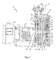
- shows a section through the endless cable winch as per Figure 1; and
- Figure 5
- shows a rear view of the endless cable winch as per Figure 1, but after removal of the housing cover of the safety device.
- Figure 1 shows a perspective view of the
endless cable winch 10. Theendless cable winch 10 comprises awinch 22 which moves a workingcable 28 upwards or downwards such that a load located thereon, e.g. lift cage, moves upwards or downwards on the workingcable 28. Thewinch 22 comprises adrive 24 with a motor and a gearbox, and also comprises acontroller 26. - In the situation illustrated here, in which people are conveyed, the
endless cable winch 10 also comprises asafety device 30 through which asafety cable 16 is guided. If, by contrast, theendless cable winch 10 is used merely for transporting materials, it is possible to dispense with thesafety cable 16 and thesafety device 30. Thewinch 22 and thesafety device 30 are accommodated in acommon housing 54. - The
endless cable winch 10 is designed for a certain rated load, for example 600 kg. To avoid overloading, or to avoid accidents in the event of overloading, theendless cable winch 10 has an overload detection device denoted as a whole by 11. Theoverload detection device 11 monitors the force acting on the workingcable 28. If the rated load is exceeded, for example by 25%, theoverload detection device 11 identifies an overload state. In this case, the drive is immediately stopped and a warning signal is output. -
Figures 2 and 3 show theendless cable winch 10 in a front view. Theendless cable winch 10 is fastened to twobeams rear beam 23 is illustrated inFigure 2 , whereasFigure 3 shows thefront beam 21 which faces toward the viewer. - For the purpose of monitoring the load acting on the working
cable 28, thehousing 54 is held at a first end so as to be pivotable about apivot axis 12. At the opposite, second end, thehousing 54 is held on aspring 14 which is held with one end in ahousing recess 17 and which is fastened with its other end to a beam on which thehousing 54 is held. The spring acts on thehousing 54 of the endless cable winch. Asensor 13 is fastened to thehousing 54. Aholder 15 comprises an adjustingscrew 18 by means of which the value for the overload can be finely adjusted. Thesensor 13 may for example be in the form of an electrical contact sensor which closes an electrical circuit when a contact-making end of thespring 14 makes contact. Various other embodiments of thesensor 13 are conceivable which respond when thehousing 54 pivots about thepivot axis 12 by a certain pivot angle. This sensor could therefore for example also be a travel sensor in the form of a strain gauge or the like. - When the
sensor 13 responds, thehousing 54 has pivoted by a certain pivot angle as a result of the force acting on the working cable. The spring characteristic and the sensor are preferably coordinated with one another such that thesensor 13 responds when 125 % of the rated load of theendless cable winch 10 is reached, that is to say at 750 kg in the case of a rated load of 600 kg. This corresponds to the EN1808 standard. - If the
sensor 13 responds, the drive is automatically stopped and a warning signal, for example a visual warning signal and an acoustic warning signal, is output. Furthermore, the overload state may be transmitted electrically to further elements via a signal line. Since the overload generally occurs when theendless cable winch 10 is at a standstill, the drive cannot start in this case, and, as a result of the warning signal output, a user will generally immediately recognize the overload, such that he can correspondingly reduce the load. - The further construction of the
winch 22 and of thesafety device 30 can be seen fromFigure 4 . - The
winch 22 has a drivingcable pulley 58 over which the workingcable 28 is guided with a wrap angle of approximately 270°. The drivingcable pulley 58 has aguide groove 59 in which the workingcable 28 runs. A biasingdevice 56 is also provided for biasing or pressing the workingcable 28 into theguide groove 59. This biasing device involves a pressing roller combined with a spring. The workingcable 28 emerges laterally out of thewinch 22, as can be seen from Figure 1, after a wrap angle of approximately 270°, and can optionally then be diverted downwards by means of a diverting roller. -
Figure 4 also shows thedrive 24 which comprises an electric motor and a gearbox. Theoutput shaft 70 of the gearbox drives the drivingcable pulley 58 via a shaft-type pinion (not illustrated). - As can also be seen from
Figure 4 , both the drivingcable pulley 58 and also thecable pulley 68 are each mounted in thecommon housing 54 of thewinch 22 and of thesafety device 30 by means of twobearings - The
safety device 30 comprises an arrestingdevice 31, the safety device being coupled by means of a brake, denoted as a whole by numeral 71, to acable pulley 68 over which thesafety cable 16 is guided. If the arrestingdevice 31 arrests thesafety cable 16 when a certain speed is reached, thecable pulley 68 is braked via thebrake 71. - The arresting
device 31 comprises a rotatably mountedratchet wheel 32, which interacts with apawl 34 which is pivotably mounted on thehousing 54. Theratchet wheel 32 has anexternal cone 72 which bears against aninternal cone 74 of thecable pulley 68. Theratchet wheel 32 is preloaded against thecable pulley 68 by means of aplate spring 78 which is supported against a bearingring 76 on ajournal 73 of the cable pulley, such that there is frictional engagement between theexternal cone 72 of theratchet wheel 32 and theinternal cone 74 of thecable pulley 68. The preload of theplate spring 78 can be adjusted by means of a nut 82 which is screwed onto a thread 80 on thejournal 73. A biasing device 48, consisting of spring and pressing roller, is also provided for thecable pulley 68, for pressing thesafety cable 16 into the guide groove provided therefor. - Figure 5 shows in more detail the construction of the arresting
device 31 which is part of thesafety device 30. Thepawl 34 is held so as to be pivotable about apivot axis 36. Thepawl 34 has afirst pawl arm 38 and asecond pawl arm 40 which protrude in opposite directions from thepivot axis 36. Thepawl 34 is preloaded by aspring 46, which is accommodated on aholder 44, in such a way that thefirst pawl arm 38 normally bears against the internal toothing of theratchet wheel 32. In this position, the ratchet wheel can be moved both clockwise and also anticlockwise without the pawl leading to blocking against theratchet wheel 32. - If the
ratchet wheel 32 moves anticlockwise as per the illustration in Figure 5, a load accommodated on theendless cable winch 10, for instance a lift cage, moves downwards. Here, thepawl 34 runs with itsfirst pawl arm 38 on the toothed inner surface of theratchet wheel 32. The stress of thespring 46 is now set such that, when the downward speed of thesafety cable 16 reaches approximately 30 metres per minute, the interaction of thefirst pawl arm 38 with the toothed inner surface of theratchet wheel 32 causes thepawl 34 to lift from the inner surface of theratchet wheel 32 and turn over, such that the pawl latches with a latchinglug 42 at the end of the second pawl arm into the inner surface of theratchet wheel 32, and theratchet wheel 32 is thus blocked by means of thepawl 34 mounted in thehousing 54. The arrestingdevice 31 is thus arrested and causes the rotatably mountedratchet wheel 32 to be fixed at thepawl 34. A response of the arrestingdevice 31 is signalled by theswitch 44. - The function of the
safety device 30 is as follows: - In the normal situation, the
non-driven cable pulley 68 runs synchronously with the drivingcable pulley 58. Thesafety cable 16 thus moves at the same speed as the workingcable 28 over thecable pulley 68. - If, for any reason, the
winch 22 fails, either as a result of breakage of the workingcable 28 or gearbox failure in thedrive 24, which would cause the load accommodated on theendless cable winch 10 to fall downwards, the load moves downwards initially at an increased speed until the triggering speed of the arrestingdevice 31 is reached. At approximately 30 metres per minute, thepawl 34 blocks against theratchet wheel 32, such that the previously rotatingcable pulley 68 is now braked by means of theconical brake 71 until thesafety cable 16 finally comes to a standstill. - By means of a
button 45, thepawl 34 can also be moved into its arresting position manually, mechanically, electrically or in some other way. For this purpose, thebutton 45 is actuated once in order to pivot thepawl 34. The arresting position is automatically eliminated again if thesafety cable 16 is moved in the upward direction again.
Claims (15)
- An endless cable winch, comprising a working cable (28), a housing (54), in which is mounted a driving cable pulley (58) around at least a part of which the working cable (28) is wrapped, and a drive (24) for driving the driving cable pulley (58), and further comprising an overload detection device (11) for detecting an overload of the working cable (28) whereby the housing (54) is mounted so as to be pivotable about a pivot axis (12), and characterized in that a sensor (13) for detecting a pivoting movement of the housing (54) is provided.
- The endless cable winch according to claim 1, characterized in that the housing (54) is pivotably mounted at a first end, and is suspended at a second end from an elongation element (14).
- The endless cable winch according to claim 2, characterized in that the elongation element (14) is in the form of a spring element.
- The endless cable winch according to any of the preceding claims, characterized in that the sensor (13) is in the form of a travel sensor, elongation sensor, contact sensor, piezo sensor, magnetic sensor or movement sensor.
- The endless cable winch according to any of the preceding claims, characterized in that the drive (24) is shut off when the sensor (13) responds.
- The endless cable winch according to any of the preceding claims, characterized in that a signal which indicates an overload state is output when the sensor (13) responds, for example in order to output a warning signal.
- The endless cable winch according to any of the preceding claims, characterized in that the working cable (28) is wrapped around the driving cable pulley (58) with a wrap angle of less than 300°, preferably of approximately 260 to 280°, particularly preferably of approximately 270°.
- The endless cable winch according to any of the preceding claims, characterized in that a safety device (30) with a safety cable (16) is provided, said safety device (30) comprising a non-driven cable pulley (68), which is rotatably mounted in a housing (54) and around at least a part of which the safety cable (16) is wrapped, and further comprises an arresting device (31) which is coupled via a brake (71) to the cable pulley (68) and which blocks and brakes the safety cable (16) by means of the brake (71), at a predetermined speed of the safety cable (16) at least in one direction.
- The endless cable winch according to claim 8, characterized in that the arresting device (31) comprises a ratchet wheel (32) which interacts with a pawl (34) mounted on the housing (54), in such a way that the pawl (34) latches into the ratchet wheel (32) at the predetermined speed of the safety cable (16).
- The endless cable winch according to any of claims 8 or 9, characterized in that the pawl (34) comprises a first pawl arm (38) and a second pawl arm (40), between which the pawl (34) is pivotably mounted on the housing (54), wherein the pawl (34) is preloaded against the ratchet wheel (32) in such a way that the first pawl arm (38) can move along the ratchet wheel (32) up to the predetermined speed, and latches with its second pawl arm (40) into the ratchet wheel (32) if the predetermined speed is exceeded in the downward direction of the safety cable (16).
- The endless cable winch according to any of claims 8 to 10, characterized in that a sensor (44) is provided which indicates a response of the arresting device (31).
- The endless cable winch according to any of claims 8 to 11, characterized in that the brake (71) is in the form of a conical brake.
- The endless cable winch according to any of claims 8 to 12, characterized in that the ratchet wheel (32) comprises an external cone (72) which is spring-loaded against an internal cone (74) of the cable pulley (68).
- The endless cable winch according to any of claims 8 to 13, characterized in that the driving cable pulley (58) and the cable pulley (68) are mounted in a common housing (54).
- The endless cable winch according to any of the preceding claims, characterized in that at least the driving cable pulley (58) or the cable pulley (68) comprise a biasing device (56, 48) for biasing the working cable (28) or the safety cable (16).
Priority Applications (1)
| Application Number | Priority Date | Filing Date | Title |
|---|---|---|---|
| PL12730581T PL2729400T3 (en) | 2011-07-04 | 2012-07-02 | Endless cable winch |
Applications Claiming Priority (2)
| Application Number | Priority Date | Filing Date | Title |
|---|---|---|---|
| DE102011106635A DE102011106635A1 (en) | 2011-07-04 | 2011-07-04 | Cable winch |
| PCT/EP2012/062841 WO2013004663A1 (en) | 2011-07-04 | 2012-07-02 | Endless cable winch |
Publications (2)
| Publication Number | Publication Date |
|---|---|
| EP2729400A1 EP2729400A1 (en) | 2014-05-14 |
| EP2729400B1 true EP2729400B1 (en) | 2015-09-09 |
Family
ID=46397306
Family Applications (1)
| Application Number | Title | Priority Date | Filing Date |
|---|---|---|---|
| EP12730581.1A Active EP2729400B1 (en) | 2011-07-04 | 2012-07-02 | Endless cable winch |
Country Status (12)
| Country | Link |
|---|---|
| US (1) | US9422140B2 (en) |
| EP (1) | EP2729400B1 (en) |
| JP (2) | JP2014522792A (en) |
| CN (1) | CN103648960B (en) |
| BR (1) | BR112013032508B1 (en) |
| CA (1) | CA2839184C (en) |
| DE (1) | DE102011106635A1 (en) |
| DK (1) | DK2729400T3 (en) |
| ES (1) | ES2550673T3 (en) |
| MX (1) | MX336083B (en) |
| PL (1) | PL2729400T3 (en) |
| WO (1) | WO2013004663A1 (en) |
Families Citing this family (8)
| Publication number | Priority date | Publication date | Assignee | Title |
|---|---|---|---|---|
| EP2910514B1 (en) * | 2009-11-18 | 2016-10-19 | Electronic Theatre Controls, Inc. | Lift assembly systems and methods |
| EP3045419A1 (en) * | 2015-01-15 | 2016-07-20 | Siemens Aktiengesellschaft | Safety brake for a lifting device |
| DE102015109609A1 (en) * | 2015-06-16 | 2016-12-22 | Terex MHPS IP Management GmbH | Overload protection for a hoist and hoist hereby |
| CN111655606A (en) | 2018-01-05 | 2020-09-11 | 安全工业责任有限公司 | Promise cable winch |
| CN110040643B (en) * | 2019-05-17 | 2023-10-20 | 黄河科技学院 | Electric winch assembly with force measuring function |
| TWI717270B (en) * | 2020-04-30 | 2021-01-21 | 徐瑞峯 | Structure of electric winch |
| US20230348242A1 (en) * | 2022-04-29 | 2023-11-02 | Atlanta Rigging & Staging Services, Llc | Hoist system |
| CN115979338B (en) * | 2022-12-07 | 2025-09-19 | 北京新兴东方航空装备股份有限公司 | Comprehensive measurement device for cable operation parameters of dual-redundancy winch |
Family Cites Families (27)
| Publication number | Priority date | Publication date | Assignee | Title |
|---|---|---|---|---|
| GB256916A (en) * | 1925-08-11 | 1927-02-14 | Pierre Eugene Leroux | Improvements in capstans or winches |
| DE816731C (en) * | 1949-09-10 | 1951-10-11 | Flohr Aufzugs G M B H | Elevator with safety rope |
| DE955180C (en) * | 1954-09-08 | 1956-12-27 | Augsburg Nuernberg A G Zweigni | Overfill protection for cranes with a three-point lift winch supported on the drum shaft |
| JPS4922683Y1 (en) * | 1970-09-05 | 1974-06-18 | ||
| CA988476A (en) * | 1972-05-22 | 1976-05-04 | Masao Tsuda | Slow descender |
| CH541510A (en) * | 1972-07-14 | 1973-09-15 | Kern Ag Conrad | Drive for a rope arrangement used to suspend a load, in particular a lifting platform or the like |
| US3944185A (en) * | 1974-06-28 | 1976-03-16 | Mayco Equipment Co., Inc. | Hoist apparatus |
| US3912093A (en) * | 1974-10-11 | 1975-10-14 | Peterson Tractor Co | Hoist truck with planetary gear assemblies and load sensor means |
| FR2457834A1 (en) * | 1979-06-01 | 1980-12-26 | Tractel Sa | DEVICE FOR PRESSING A CABLE AGAINST THE GROOVE OF A PULLEY |
| FR2618421B1 (en) * | 1987-07-21 | 1990-01-05 | Cavalieri Michel | SAFETY ASSEMBLY FOR FLYING SCAFFOLD WINCH |
| DE3819447A1 (en) * | 1988-06-08 | 1989-12-14 | Mak Maschinenbau Krupp | DEVICE FOR REGULATING THE TOWING CAPACITY OF A WINCH |
| EP0363800B1 (en) * | 1988-10-13 | 1994-01-19 | Power Climber Inc. | Hoist apparatus |
| US5090666A (en) * | 1988-10-13 | 1992-02-25 | May Marvin M | Hoist apparatus |
| DE9110989U1 (en) * | 1991-09-05 | 1993-01-21 | Maschinenfabrik Julius Marbaise GmbH & Co KG, 4600 Dortmund | Planetary spur gear with power division as cable winch with overload protection in lightweight construction |
| US5361565A (en) * | 1993-01-19 | 1994-11-08 | Bayer Robert F | Elevating system |
| JP2852731B2 (en) * | 1996-02-26 | 1999-02-03 | 象印チエンブロック株式会社 | Electric hoist |
| FR2753188B1 (en) * | 1996-09-10 | 1998-12-11 | Reel Sa | METHOD FOR CONTROLLING THE OPERATION OF A CHARGE COMPENSATOR DEVICE AND CHARGE COMPENSATOR IMPLEMENTING SAID METHOD |
| DE29702760U1 (en) * | 1997-02-17 | 1998-06-18 | Gesellschaft für Antriebstechnik Dr. Ing. Günther Hammann GmbH & Co. KG, 40549 Düsseldorf | Safety gear for a winding shaft |
| DE29704761U1 (en) * | 1997-03-15 | 1997-05-15 | Carl Stahl Kromer GmbH, 79224 Umkirch | Device for balancing the weight of a hanging load |
| DE10205434A1 (en) * | 2002-02-07 | 2003-08-28 | Demag Mobile Cranes Gmbh | Load sensing device on a hoist |
| DE20217287U1 (en) * | 2002-11-09 | 2003-03-06 | System Antriebstechnik Dresden Gmbh, 01189 Dresden | Belt-driven lift machine with emergency brake is for lift cage guided on rails in shaft and suspended on support devices |
| CN2637460Y (en) * | 2003-04-23 | 2004-09-01 | 张忠伟 | Hand operated hoist |
| DE102004010308B4 (en) * | 2004-03-03 | 2006-07-27 | Greifzug Hebezeugbau Gmbh | Traction sheave hoist for the stage and access system hereby |
| US7624967B1 (en) * | 2006-04-19 | 2009-12-01 | Par Systems, Inc. | Opposed-rope hoist driven telescoping mast |
| US7311297B1 (en) * | 2007-02-01 | 2007-12-25 | Bradshaw Franklin C | Electric powered lift with load control |
| US8403302B2 (en) * | 2008-09-04 | 2013-03-26 | Videolarm, Inc. | Elevated support system |
| US9700810B2 (en) * | 2012-12-21 | 2017-07-11 | Donald Aloysius Hoffend, Jr. | Compact hoist system |
-
2011
- 2011-07-04 DE DE102011106635A patent/DE102011106635A1/en not_active Ceased
-
2012
- 2012-07-02 MX MX2014000019A patent/MX336083B/en unknown
- 2012-07-02 WO PCT/EP2012/062841 patent/WO2013004663A1/en not_active Ceased
- 2012-07-02 ES ES12730581.1T patent/ES2550673T3/en active Active
- 2012-07-02 CA CA2839184A patent/CA2839184C/en active Active
- 2012-07-02 PL PL12730581T patent/PL2729400T3/en unknown
- 2012-07-02 BR BR112013032508-9A patent/BR112013032508B1/en active IP Right Grant
- 2012-07-02 CN CN201280033248.7A patent/CN103648960B/en active Active
- 2012-07-02 JP JP2014517759A patent/JP2014522792A/en active Pending
- 2012-07-02 DK DK12730581.1T patent/DK2729400T3/en active
- 2012-07-02 EP EP12730581.1A patent/EP2729400B1/en active Active
-
2014
- 2014-01-02 US US14/146,384 patent/US9422140B2/en active Active
-
2017
- 2017-07-14 JP JP2017138200A patent/JP6655047B2/en active Active
Also Published As
| Publication number | Publication date |
|---|---|
| US20140110650A1 (en) | 2014-04-24 |
| DK2729400T3 (en) | 2015-12-21 |
| DE102011106635A1 (en) | 2013-01-10 |
| US9422140B2 (en) | 2016-08-23 |
| PL2729400T3 (en) | 2016-01-29 |
| BR112013032508A2 (en) | 2017-03-01 |
| EP2729400A1 (en) | 2014-05-14 |
| CA2839184C (en) | 2019-06-04 |
| BR112013032508B1 (en) | 2021-04-20 |
| CN103648960A (en) | 2014-03-19 |
| MX336083B (en) | 2016-01-05 |
| JP6655047B2 (en) | 2020-02-26 |
| JP2014522792A (en) | 2014-09-08 |
| CA2839184A1 (en) | 2013-01-10 |
| ES2550673T3 (en) | 2015-11-11 |
| CN103648960B (en) | 2016-10-19 |
| MX2014000019A (en) | 2014-08-22 |
| WO2013004663A1 (en) | 2013-01-10 |
| JP2017197388A (en) | 2017-11-02 |
Similar Documents
| Publication | Publication Date | Title |
|---|---|---|
| US9422140B2 (en) | Endless cable winch with overload protection | |
| EP2729399B1 (en) | Endless cable winch | |
| US8827044B2 (en) | Over-acceleration and over-speed detection and processing system | |
| US8939262B2 (en) | Elevator over-acceleration and over-speed protection system | |
| US8631909B2 (en) | Electromagnetic safety trigger | |
| US20130105250A1 (en) | Speed limiter for an elevator | |
| CN105473487B (en) | Overspeed governor tension roller component | |
| JPH061561A (en) | Governor for elevator | |
| CN105392729B (en) | Speed regulator for elevator and the lift appliance using this speed regulator for elevator | |
| CN114148851A (en) | Overspeed governor rope overspeed device tensioner |
Legal Events
| Date | Code | Title | Description |
|---|---|---|---|
| PUAI | Public reference made under article 153(3) epc to a published international application that has entered the european phase |
Free format text: ORIGINAL CODE: 0009012 |
|
| 17P | Request for examination filed |
Effective date: 20131213 |
|
| AK | Designated contracting states |
Kind code of ref document: A1 Designated state(s): AL AT BE BG CH CY CZ DE DK EE ES FI FR GB GR HR HU IE IS IT LI LT LU LV MC MK MT NL NO PL PT RO RS SE SI SK SM TR |
|
| DAX | Request for extension of the european patent (deleted) | ||
| GRAP | Despatch of communication of intention to grant a patent |
Free format text: ORIGINAL CODE: EPIDOSNIGR1 |
|
| INTG | Intention to grant announced |
Effective date: 20150204 |
|
| GRAS | Grant fee paid |
Free format text: ORIGINAL CODE: EPIDOSNIGR3 |
|
| GRAA | (expected) grant |
Free format text: ORIGINAL CODE: 0009210 |
|
| AK | Designated contracting states |
Kind code of ref document: B1 Designated state(s): AL AT BE BG CH CY CZ DE DK EE ES FI FR GB GR HR HU IE IS IT LI LT LU LV MC MK MT NL NO PL PT RO RS SE SI SK SM TR |
|
| REG | Reference to a national code |
Ref country code: GB Ref legal event code: FG4D |
|
| REG | Reference to a national code |
Ref country code: AT Ref legal event code: REF Ref document number: 747970 Country of ref document: AT Kind code of ref document: T Effective date: 20150915 Ref country code: CH Ref legal event code: EP |
|
| REG | Reference to a national code |
Ref country code: IE Ref legal event code: FG4D |
|
| REG | Reference to a national code |
Ref country code: DE Ref legal event code: R096 Ref document number: 602012010372 Country of ref document: DE |
|
| REG | Reference to a national code |
Ref country code: ES Ref legal event code: FG2A Ref document number: 2550673 Country of ref document: ES Kind code of ref document: T3 Effective date: 20151111 |
|
| REG | Reference to a national code |
Ref country code: NL Ref legal event code: FP |
|
| REG | Reference to a national code |
Ref country code: DK Ref legal event code: T3 Effective date: 20151214 |
|
| PG25 | Lapsed in a contracting state [announced via postgrant information from national office to epo] |
Ref country code: GR Free format text: LAPSE BECAUSE OF FAILURE TO SUBMIT A TRANSLATION OF THE DESCRIPTION OR TO PAY THE FEE WITHIN THE PRESCRIBED TIME-LIMIT Effective date: 20151210 Ref country code: FI Free format text: LAPSE BECAUSE OF FAILURE TO SUBMIT A TRANSLATION OF THE DESCRIPTION OR TO PAY THE FEE WITHIN THE PRESCRIBED TIME-LIMIT Effective date: 20150909 Ref country code: LV Free format text: LAPSE BECAUSE OF FAILURE TO SUBMIT A TRANSLATION OF THE DESCRIPTION OR TO PAY THE FEE WITHIN THE PRESCRIBED TIME-LIMIT Effective date: 20150909 Ref country code: NO Free format text: LAPSE BECAUSE OF FAILURE TO SUBMIT A TRANSLATION OF THE DESCRIPTION OR TO PAY THE FEE WITHIN THE PRESCRIBED TIME-LIMIT Effective date: 20151209 Ref country code: LT Free format text: LAPSE BECAUSE OF FAILURE TO SUBMIT A TRANSLATION OF THE DESCRIPTION OR TO PAY THE FEE WITHIN THE PRESCRIBED TIME-LIMIT Effective date: 20150909 |
|
| REG | Reference to a national code |
Ref country code: LT Ref legal event code: MG4D |
|
| REG | Reference to a national code |
Ref country code: AT Ref legal event code: MK05 Ref document number: 747970 Country of ref document: AT Kind code of ref document: T Effective date: 20150909 |
|
| PG25 | Lapsed in a contracting state [announced via postgrant information from national office to epo] |
Ref country code: RS Free format text: LAPSE BECAUSE OF FAILURE TO SUBMIT A TRANSLATION OF THE DESCRIPTION OR TO PAY THE FEE WITHIN THE PRESCRIBED TIME-LIMIT Effective date: 20150909 Ref country code: SE Free format text: LAPSE BECAUSE OF FAILURE TO SUBMIT A TRANSLATION OF THE DESCRIPTION OR TO PAY THE FEE WITHIN THE PRESCRIBED TIME-LIMIT Effective date: 20150909 Ref country code: HR Free format text: LAPSE BECAUSE OF FAILURE TO SUBMIT A TRANSLATION OF THE DESCRIPTION OR TO PAY THE FEE WITHIN THE PRESCRIBED TIME-LIMIT Effective date: 20150909 |
|
| PG25 | Lapsed in a contracting state [announced via postgrant information from national office to epo] |
Ref country code: SK Free format text: LAPSE BECAUSE OF FAILURE TO SUBMIT A TRANSLATION OF THE DESCRIPTION OR TO PAY THE FEE WITHIN THE PRESCRIBED TIME-LIMIT Effective date: 20150909 Ref country code: EE Free format text: LAPSE BECAUSE OF FAILURE TO SUBMIT A TRANSLATION OF THE DESCRIPTION OR TO PAY THE FEE WITHIN THE PRESCRIBED TIME-LIMIT Effective date: 20150909 Ref country code: CZ Free format text: LAPSE BECAUSE OF FAILURE TO SUBMIT A TRANSLATION OF THE DESCRIPTION OR TO PAY THE FEE WITHIN THE PRESCRIBED TIME-LIMIT Effective date: 20150909 Ref country code: IS Free format text: LAPSE BECAUSE OF FAILURE TO SUBMIT A TRANSLATION OF THE DESCRIPTION OR TO PAY THE FEE WITHIN THE PRESCRIBED TIME-LIMIT Effective date: 20160109 |
|
| PG25 | Lapsed in a contracting state [announced via postgrant information from national office to epo] |
Ref country code: AT Free format text: LAPSE BECAUSE OF FAILURE TO SUBMIT A TRANSLATION OF THE DESCRIPTION OR TO PAY THE FEE WITHIN THE PRESCRIBED TIME-LIMIT Effective date: 20150909 Ref country code: RO Free format text: LAPSE BECAUSE OF FAILURE TO SUBMIT A TRANSLATION OF THE DESCRIPTION OR TO PAY THE FEE WITHIN THE PRESCRIBED TIME-LIMIT Effective date: 20150909 Ref country code: PT Free format text: LAPSE BECAUSE OF FAILURE TO SUBMIT A TRANSLATION OF THE DESCRIPTION OR TO PAY THE FEE WITHIN THE PRESCRIBED TIME-LIMIT Effective date: 20160111 |
|
| REG | Reference to a national code |
Ref country code: DE Ref legal event code: R097 Ref document number: 602012010372 Country of ref document: DE |
|
| PLBE | No opposition filed within time limit |
Free format text: ORIGINAL CODE: 0009261 |
|
| STAA | Information on the status of an ep patent application or granted ep patent |
Free format text: STATUS: NO OPPOSITION FILED WITHIN TIME LIMIT |
|
| REG | Reference to a national code |
Ref country code: FR Ref legal event code: PLFP Year of fee payment: 5 |
|
| 26N | No opposition filed |
Effective date: 20160610 |
|
| PG25 | Lapsed in a contracting state [announced via postgrant information from national office to epo] |
Ref country code: SI Free format text: LAPSE BECAUSE OF FAILURE TO SUBMIT A TRANSLATION OF THE DESCRIPTION OR TO PAY THE FEE WITHIN THE PRESCRIBED TIME-LIMIT Effective date: 20150909 |
|
| REG | Reference to a national code |
Ref country code: CH Ref legal event code: PL |
|
| PG25 | Lapsed in a contracting state [announced via postgrant information from national office to epo] |
Ref country code: MC Free format text: LAPSE BECAUSE OF FAILURE TO SUBMIT A TRANSLATION OF THE DESCRIPTION OR TO PAY THE FEE WITHIN THE PRESCRIBED TIME-LIMIT Effective date: 20150909 |
|
| PG25 | Lapsed in a contracting state [announced via postgrant information from national office to epo] |
Ref country code: CH Free format text: LAPSE BECAUSE OF NON-PAYMENT OF DUE FEES Effective date: 20160731 Ref country code: LI Free format text: LAPSE BECAUSE OF NON-PAYMENT OF DUE FEES Effective date: 20160731 |
|
| REG | Reference to a national code |
Ref country code: IE Ref legal event code: MM4A |
|
| REG | Reference to a national code |
Ref country code: FR Ref legal event code: PLFP Year of fee payment: 6 |
|
| PG25 | Lapsed in a contracting state [announced via postgrant information from national office to epo] |
Ref country code: IE Free format text: LAPSE BECAUSE OF NON-PAYMENT OF DUE FEES Effective date: 20160702 |
|
| PG25 | Lapsed in a contracting state [announced via postgrant information from national office to epo] |
Ref country code: LU Free format text: LAPSE BECAUSE OF NON-PAYMENT OF DUE FEES Effective date: 20160702 |
|
| PG25 | Lapsed in a contracting state [announced via postgrant information from national office to epo] |
Ref country code: HU Free format text: LAPSE BECAUSE OF FAILURE TO SUBMIT A TRANSLATION OF THE DESCRIPTION OR TO PAY THE FEE WITHIN THE PRESCRIBED TIME-LIMIT; INVALID AB INITIO Effective date: 20120702 Ref country code: SM Free format text: LAPSE BECAUSE OF FAILURE TO SUBMIT A TRANSLATION OF THE DESCRIPTION OR TO PAY THE FEE WITHIN THE PRESCRIBED TIME-LIMIT Effective date: 20150909 Ref country code: CY Free format text: LAPSE BECAUSE OF FAILURE TO SUBMIT A TRANSLATION OF THE DESCRIPTION OR TO PAY THE FEE WITHIN THE PRESCRIBED TIME-LIMIT Effective date: 20150909 |
|
| PG25 | Lapsed in a contracting state [announced via postgrant information from national office to epo] |
Ref country code: MT Free format text: LAPSE BECAUSE OF NON-PAYMENT OF DUE FEES Effective date: 20160731 Ref country code: MK Free format text: LAPSE BECAUSE OF FAILURE TO SUBMIT A TRANSLATION OF THE DESCRIPTION OR TO PAY THE FEE WITHIN THE PRESCRIBED TIME-LIMIT Effective date: 20150909 |
|
| REG | Reference to a national code |
Ref country code: FR Ref legal event code: PLFP Year of fee payment: 7 |
|
| PG25 | Lapsed in a contracting state [announced via postgrant information from national office to epo] |
Ref country code: BG Free format text: LAPSE BECAUSE OF FAILURE TO SUBMIT A TRANSLATION OF THE DESCRIPTION OR TO PAY THE FEE WITHIN THE PRESCRIBED TIME-LIMIT Effective date: 20150909 |
|
| PG25 | Lapsed in a contracting state [announced via postgrant information from national office to epo] |
Ref country code: AL Free format text: LAPSE BECAUSE OF FAILURE TO SUBMIT A TRANSLATION OF THE DESCRIPTION OR TO PAY THE FEE WITHIN THE PRESCRIBED TIME-LIMIT Effective date: 20150909 |
|
| PGFP | Annual fee paid to national office [announced via postgrant information from national office to epo] |
Ref country code: PL Payment date: 20250623 Year of fee payment: 14 |
|
| PGFP | Annual fee paid to national office [announced via postgrant information from national office to epo] |
Ref country code: TR Payment date: 20250624 Year of fee payment: 14 |
|
| PGFP | Annual fee paid to national office [announced via postgrant information from national office to epo] |
Ref country code: NL Payment date: 20250721 Year of fee payment: 14 |
|
| PGFP | Annual fee paid to national office [announced via postgrant information from national office to epo] |
Ref country code: ES Payment date: 20250826 Year of fee payment: 14 |
|
| PGFP | Annual fee paid to national office [announced via postgrant information from national office to epo] |
Ref country code: DK Payment date: 20250725 Year of fee payment: 14 Ref country code: DE Payment date: 20250730 Year of fee payment: 14 |
|
| PGFP | Annual fee paid to national office [announced via postgrant information from national office to epo] |
Ref country code: IT Payment date: 20250724 Year of fee payment: 14 |
|
| PGFP | Annual fee paid to national office [announced via postgrant information from national office to epo] |
Ref country code: BE Payment date: 20250718 Year of fee payment: 14 Ref country code: GB Payment date: 20250722 Year of fee payment: 14 |
|
| PGFP | Annual fee paid to national office [announced via postgrant information from national office to epo] |
Ref country code: FR Payment date: 20250725 Year of fee payment: 14 |