EP2729255B1 - Material reduction machine - Google Patents
Material reduction machine Download PDFInfo
- Publication number
- EP2729255B1 EP2729255B1 EP12806943.2A EP12806943A EP2729255B1 EP 2729255 B1 EP2729255 B1 EP 2729255B1 EP 12806943 A EP12806943 A EP 12806943A EP 2729255 B1 EP2729255 B1 EP 2729255B1
- Authority
- EP
- European Patent Office
- Prior art keywords
- drum
- reduction machine
- material reduction
- interchangeable
- belly
- Prior art date
- Legal status (The legal status is an assumption and is not a legal conclusion. Google has not performed a legal analysis and makes no representation as to the accuracy of the status listed.)
- Active
Links
Images




Classifications
-
- B—PERFORMING OPERATIONS; TRANSPORTING
- B02—CRUSHING, PULVERISING, OR DISINTEGRATING; PREPARATORY TREATMENT OF GRAIN FOR MILLING
- B02C—CRUSHING, PULVERISING, OR DISINTEGRATING IN GENERAL; MILLING GRAIN
- B02C18/00—Disintegrating by knives or other cutting or tearing members which chop material into fragments
- B02C18/06—Disintegrating by knives or other cutting or tearing members which chop material into fragments with rotating knives
- B02C18/14—Disintegrating by knives or other cutting or tearing members which chop material into fragments with rotating knives within horizontal containers
-
- B—PERFORMING OPERATIONS; TRANSPORTING
- B02—CRUSHING, PULVERISING, OR DISINTEGRATING; PREPARATORY TREATMENT OF GRAIN FOR MILLING
- B02C—CRUSHING, PULVERISING, OR DISINTEGRATING IN GENERAL; MILLING GRAIN
- B02C18/00—Disintegrating by knives or other cutting or tearing members which chop material into fragments
- B02C18/06—Disintegrating by knives or other cutting or tearing members which chop material into fragments with rotating knives
- B02C18/16—Details
- B02C18/18—Knives; Mountings thereof
-
- B—PERFORMING OPERATIONS; TRANSPORTING
- B02—CRUSHING, PULVERISING, OR DISINTEGRATING; PREPARATORY TREATMENT OF GRAIN FOR MILLING
- B02C—CRUSHING, PULVERISING, OR DISINTEGRATING IN GENERAL; MILLING GRAIN
- B02C18/00—Disintegrating by knives or other cutting or tearing members which chop material into fragments
- B02C18/06—Disintegrating by knives or other cutting or tearing members which chop material into fragments with rotating knives
- B02C18/16—Details
- B02C18/22—Feed or discharge means
- B02C18/2216—Discharge means
-
- B—PERFORMING OPERATIONS; TRANSPORTING
- B27—WORKING OR PRESERVING WOOD OR SIMILAR MATERIAL; NAILING OR STAPLING MACHINES IN GENERAL
- B27L—REMOVING BARK OR VESTIGES OF BRANCHES; SPLITTING WOOD; MANUFACTURE OF VENEER, WOODEN STICKS, WOOD SHAVINGS, WOOD FIBRES OR WOOD POWDER
- B27L11/00—Manufacture of wood shavings, chips, powder, or the like; Tools therefor
- B27L11/002—Transporting devices for wood or chips
-
- B—PERFORMING OPERATIONS; TRANSPORTING
- B27—WORKING OR PRESERVING WOOD OR SIMILAR MATERIAL; NAILING OR STAPLING MACHINES IN GENERAL
- B27L—REMOVING BARK OR VESTIGES OF BRANCHES; SPLITTING WOOD; MANUFACTURE OF VENEER, WOODEN STICKS, WOOD SHAVINGS, WOOD FIBRES OR WOOD POWDER
- B27L11/00—Manufacture of wood shavings, chips, powder, or the like; Tools therefor
- B27L11/005—Tools therefor
-
- B—PERFORMING OPERATIONS; TRANSPORTING
- B27—WORKING OR PRESERVING WOOD OR SIMILAR MATERIAL; NAILING OR STAPLING MACHINES IN GENERAL
- B27L—REMOVING BARK OR VESTIGES OF BRANCHES; SPLITTING WOOD; MANUFACTURE OF VENEER, WOODEN STICKS, WOOD SHAVINGS, WOOD FIBRES OR WOOD POWDER
- B27L11/00—Manufacture of wood shavings, chips, powder, or the like; Tools therefor
- B27L11/02—Manufacture of wood shavings, chips, powder, or the like; Tools therefor of wood shavings or the like
Definitions
- the present invention relates generally to material reduction machines such as wood chippers, and more particularly, to a material reduction machine having a cylindrical drum with one or more cutting knives spaced about its circumferential wall.
- Material reduction machines are used to reduce larger pieces of material into smaller pieces by cutting, chopping, shredding or breaking.
- a material reduction machine will have an enclosure for a reducing mechanism, such as a rotating disc or drum equipped with blades, knives or hammers.
- the enclosure will typically have a feed inlet through which the larger materials to be reduced are introduced, and a discharge outlet through which the smaller materials are discharged after reduction.
- a material reduction machine is a wood chipper that is used to reduce trees and their limbs and branches to wood chips. The use of wood chippers avoids the environmental and other problems associated with burning trees and brush or with depositing them in a landfill. Furthermore, by reducing wood to chips of a useful size, a wood chipper may be employed to produce a valuable chip product.
- Wood chips can be used as mulch or fuel. They can also be used as raw material for creating a pelletized fuel product or as raw material in a chemical pulp process. Wood chips that are intended for use as fuel or in a pelletizing process may first need to be dried. It is desirable that such chips have a uniform chip thickness and a high surface area to volume ratio. It is also desirable that chips which are intended for use in a pulp process be of a uniform size. Ideal pulp chips fall into a narrow thickness range so that they can cook and delignify uniformly. Long and narrow chips and very small chips are undesirable because they can plug the pulp process screens and overcook, thereby damaging the wood fibers and reducing the strength of the pulp.
- Disc chippers include knives mounted on a rotating disc that cut across the grain of the wood stem generally perpendicular to the direction of the grain. Disc chippers create chips of a generally uniform size. However, such chippers do not have the production capacity of drum chippers.
- Drum chippers include knives mounted around the circumferential wall of a cylindrical drum that cut across the wood feed stock in a path that varies with respect to the orientation of the grain of the feed stock to the drum. In the part of the wood feed stock where the knives encounter the wood near the three o'clock or the nine o'clock position of the drum, depending on the side of entry of the feed stock, the knives pass across the wood in a direction that is perpendicular to the direction of the grain.
- the knives In the part of the feed stock where the knives encounter the wood nearer the six o'clock position of the drum, the knives pass across the wood in a path that is more parallel to the direction of the grain. Because the cutting path angle relative to the direction of the grain varies in this manner, the chips break from the feed stock differently, with the chips cut by the drum nearer its six o'clock position tending to be longer and more irregular in size.
- the cutting drum of a drum chipper is rotated in a housing having only a slightly larger diameter than the arc cut by the leading edges of the knives. Because such drum chippers are known to jam with chips and stall, some such chippers are provided with blowers or -augers to release the chips from the knives and propel them into a discharge chute. It is also known to provide a drum chipper having a pocket in the drum associated with each knife.
- U.S. Patent No. 5,005,620 describes a drum chipper in which the peripheral wall of the drum defines a spaced pocket behind each knife. Each knife in this assembly is generally centered within its pocket so that chips may enter the pocket on the leading edge side of the knife and exit the pocket on the trailing edge side of the knife.
- drum chippers As the drum rotates, wood chips cut by each knife enter the pocket on the leading edge side and pass behind the knife. The wood chips in each pocket remain in the pocket until the drum rotates to align the trailing edge side of the knife with the discharge chute, where the chips are expelled into the chute under the influence of centrifugal force.
- a material reduction machine such as a drum chipper could be provided that would allow for more control of the size and shape of chips produced. It would also be desirable if such a drum chipper could be adapted to produce wood chips that are suitable for various uses.
- upper when used in reference to a relative position or direction on or with respect to a material reduction machine, or a component or portion of such a machine, refer to a relative position or direction that is farther away from the ground on which the material reduction machine is placed for operation.
- lower when used in reference to a relative position or direction on or with respect to a material reduction machine, or a component or portion of such a machine, refer to a relative position or direction that is nearer the ground on which the material reduction machine is placed for operation.
- discharge direction means the direction that reduced material is conveyed from the discharge chute of the material reduction machine, along the centerline of the machine.
- front end and similar terms refer to the end of a material reduction machine, or a component or portion of such a machine, which is farthest from the discharge outlet of the machine.
- forward refers to a relative position or direction towards the front end of the machine.
- back end refers to the end of a material reduction machine, or a component or portion of such a machine, which is nearest the discharge outlet of the machine.
- leading edge refers to the edge of the knife or flow interrupter that first contacts material within the drum housing.
- flow diverter refers to a plate, bar, rod or other shaped component having a length that is greater than its width.
- width refers to the dimension of the machine or component in a direction that is perpendicular to the discharge direction.
- the invention comprises a material reduction machine that includes a frame, a drum housing mounted to the frame, and a drum that is mounted for rotation within the housing.
- the drum comprises a circumferential wall and a knife that is mounted on the drum with respect to the circumferential wall so that as the drum rotates, the leading edge of the knife cuts an arc that is concentric with and of a larger diameter than the circumferential wall of the drum.
- the material reduction machine also includes means for rotating the drum within the housing, a feed chute for directing material to be reduced into the drum housing and a discharge chute for directing reduced material away from the drum housing.
- the machine is characterized in that it also includes a plurality of interchangeable belly bands.
- Each belly band is adapted to be removably attached to the frame so as to form a portion of the drum housing and to provide an inner surface that forms a belly band arc portion that is concentric with and of a larger diameter than the circumferential wall of the drum, so that said belly band arc portion is adjacent to a portion of the arc cut by the leading edge of the knife.
- the plurality of interchangeable belly bands comprises a first interchangeable belly band having a smooth inner surface, and a second interchangeable belly band having a plurality of flow interrupters spaced along its inner surface.
- the invention comprises a material reduction machine such as a drum-type wood chipper.
- a material reduction machine such as a drum-type wood chipper.
- preferred wood chipper 10 includes trailer 12 that is adapted to be pulled by a tractor or other vehicle.
- Trailer 12 includes frame 14 that is supported by wheels 16 and a pair of adjustable support legs, one of which, support leg 18, is shown in Figure 1 .
- Supported on frame 14 are feed chute 20, drum housing 22, intermediate housing 24 (best shown in Figures 2-4 ), accelerator wheel housing 26 and discharge chute 28.
- Intermediate housing 24 is located downstream of drum housing 22, and accelerator wheel housing 26 is located downstream of intermediate housing 24.
- drum 32 which includes circumferential wall 34 defining its outer periphery.
- a plurality of pockets 36 are spaced around the drum and formed in the circumferential wall, and a plurality of conventional knives 38, each of which has a leading edge 39 are provided.
- a knife 38 is mounted on each of the pockets so that as drum 32 rotates, the leading edges 39 of the plurality of knives 38 cut an arc that is concentric with and of a larger diameter than the circumferential wall of the drum, as can be seen by viewing the right side of Figure 2 where a leading edge of one of the knives cuts into the wood of feed stock 40.
- a driver such as engine 41
- Engine 41 is also mounted on the frame and adapted to provide a rotational force to drum 32 within the drum housing by means of one or more drive belts or other conventional drive transfer mechanisms (not shown).
- Engine 41 is also adapted to provide a rotational force to accelerator wheel 42, which is provided with a plurality of blades 44, by means of one or more drive belts or other conventional drive transfer mechanisms (not shown).
- the accelerator wheel rotates in the same direction as drum 32 to increase the momentum of reduced material from drum 32.
- material to be reduced by material reduction machine 10 is directed into the drum housing from feed chute 20 and the reduced material is discharged through discharge chute 28 in discharge direction 46.
- Machine 10 is provided with a plurality of interchangeable belly bands, each of which is adapted to be removably attached to the frame so as to form a portion of the drum housing and to provide an inner surface that forms a belly band arc portion that is concentric with and of a larger diameter than the circumferential wall of the drum.
- These interchangeable belly bands include first interchangeable belly band 49 having a smooth inner surface (shown in. Figure 2 ) and second interchangeable belly band 50 having a plurality of flow interrupters spaced along its inner surface, such as flow interrupters 52 shown in Figures 3 and 4 .
- the belly band arc portion formed by each belly band is adjacent to a portion of the arc cut by the leading edges of the knives.
- each of flow interrupters 52 comprises abrasion-resistant material in the form of a bar having a sharp leading edge that is mounted on the inner surface of the second interchangeable belly band 50 and extends across the width of drum housing 22.
- the leading edges of flow interrupters 52 define an arc 54 that is concentric with and of a different diameter than the belly band arc portion.
- the flow interrupters may comprise discrete elements arranged in a matrix, or they may be rounded, or they may comprise minimal projections from, or depressions in, the inside surface of the belly band.
- the flow interrupters are adapted to reduce the size of the longer, more irregular chips cut from the lower portion of feed stock 40 (as shown in Figures 2-4 ), and the dimensions, number and spacing of the flow interrupters are selected.in order to maximize the production of the desired sized chip.
- a gauging assembly such as first gauging assembly 56 (shown in Figures 2-5 ) or second gauging assembly 58 (shown in Figure 6 ) or third gauging assembly 60 (shown in Figure 7 ) be located in an intermediate housing that is downstream of and adjacent to the drum.
- Each gauging assembly comprises a plurality of flow diverters that are spaced across the width of the drum so as to provide a plurality of sized openings through which reduced material from the drum may pass.
- gauging assembly 56 comprises a plurality of generally upright plates 62 that are mounted to base 64 and supported by spacing plates 66 and 68.
- Generally upright plates 46 are spaced apart across the width of intermediate housing 24 (and across the width of drum 32) between drum housing 22 and discharge chute 26 so as to provide, in cooperation with spacing plates 66 and 68, a plurality of sized openings through which reduced material such as wood chips cut by the drum may pass.
- each of generally upright plates 62 has a front side that is curved to form an arc.
- Figure 5 illustrates gauging assembly 56 as being comprised of plates 62, 66 and 68, it could alternatively be comprised of bars, rods or other shaped components.
- Figure 5 shows the gauging assembly as including ten generally upright plates and two spacing plates, different numbers of generally upright plates and spacing members may alternatively be provided.
- gauging assembly 58 includes fourteen generally upright plates 70 that are mounted to base plate 72 and supported.by spacing plates 74, 76 and 78.
- Generally upright plates 70 are adapted to be spaced apart across the width of the intermediate housing (and across the width of the drum) between the drum housing and discharge chute so as to provide, in cooperation with spacing plates 74, 76 and 78, a plurality of sized openings through which reduced material such as wood chips cut by the drum may pass.
- each of generally upright plates 70 has a front side that is curved to form an arc.
- Gauging assembly 60 shown in Figure 7 , is of a construction similar to that of gauging assemblies 56 and 58. The gauging assemblies may impede the progress of long or large chips in the discharge direction, allowing,such chips to be carried around the drum housing by the rotation of the drum for further reduction.
- the gauging assembly is mounted with respect to the frame so as to be adjustable with respect thereto and/or with respect to the circumferential wall of the drum. It is also preferred that each of the plurality of interchangeable belly bands is adapted to be adjustably attached to the frame.
- gauging assembly 58 includes a pair of side supports 80 that are welded or otherwise attached to base plate 72. Gauging assembly 58 is adapted to be attached to the frame of the material reduction machine by means of bolts (such as bolts 82) that are passed through generally vertically oriented slots 84 in side supports 80.
- Base plate 72 has a front end portion 86 that has a plurality of generally horizontally oriented slots 88 spaced across its width.
- Belly band assembly 89 Located on the downstream end of belly band assembly 89 is rear support 90, the lower side of which is provided with a plurality of holes (not shown) that are spaced across the width of the belly band assembly and adapted to align with slots 88 so as to permit generally horizontal adjustment of the gauging assembly with respect to the belly band assembly.
- Belly band assembly 89 also includes a pair of side supports 92, and each of the side supports includes a plurality of parallel slots 94. Each parallel slot 94 is adapted to be aligned with a hole (not shown) in the frame, so that a bolt place through the hole in the frame and through the slot may be tightened in a plurality of positions along the slot.
- belly band assembly 89 is adapted to be attached to the frame so as to be vertically adjustable with respect thereto. Furthermore, the cooperation of slots 88 in front end portion 86 of base plate 72 and the adjacent aligned holes in the lower side of rear support 90 of the belly band, and the cooperation of slots 94 in side supports 92 of belly band assembly 92 and the adjacent aligned holes in the frame (not shown), and the cooperation of slots 84 in side supports 80 of gauging assembly 58 with adjacent aligned holes in the frame (not shown) will allow for adjustment of the gauging assembly with respect to the circumferential wall of the drum.
- FIG. 7 shows material reduction machine 110, which is similar to material reduction machine 10, but does not include an accelerator wheel.
- drum 132 which includes circumferential wall 134 and pockets 136.
- Knives 138 are mounted on the drum with respect to the circumferential wall so that as the drum rotates, the leading edges of the knives cut an arc that is concentric with and of a larger diameter than the circumferential wall of the drum.
- Machine 110 also includes a plurality of interchangeable belly bands, including belly band assembly 148, which is adjustable with respect to the frame in the same manner as belly band assembly 89 of Figure 6 .
- machine 110 includes gauging assembly 60, which is ajustable with respect to the frame and/or with respect to the circumferential wall of the drum.
- the knives pass across the feed stock in a path that is more parallel to the direction of the grain. Because the cutting path angle relative to the direction of the grain varies in this manner, the chips break from the feed stock differently, with the chips from the lower portion (as viewed in Figure 2 ) tending to be longer and more irregular in size.
- the smooth-surfaced belly band 48 shown in Figure 2 may be replaced with belly band 50 shown in Figures 3 and 4 .
- leading edges 39 of knives 38 will first pass across top portion 96 of the wood of feed stock 40.
- the knives pass across the feed stock in a direction that is perpendicular to the direction of the grain, thus producing uniformly sized chips.
- the knives continue to produce uniformly sized chips that partially fill the associated pockets.
- the knives pass across the feed stock in a path that is more parallel to the direction of the grain. Because the cutting path angle relative to the direction of the grain varies in this manner, the chips break from the feed stock differently, with the chips cut from the lower portion of the feed stock (as viewed in Figures 3 and 4 ) tending to be longer and more irregular in size. These chips are collected in the radially-outer part of the associated pocket. As the drum continues to rotate, the collected chips pass across the flow interrupters 52, where the irregularly sized chips in the pocket are repeatedly impacted by the flow interrupters and/or the knives and are further reduced.
- the pocket will align with.intermediate housing 24 which includes gauging assembly 56.
- the chips pass out of pocket 36 and pass through the gauging assembly into accelerator wheel housing 26.
- Accelerator wheel 42 is adapted to be rotated in a direction that is selected to increase the momentum of the chips passing through gauging assembly 56 and into discharge chute 28.
- the present invention comprises a material reduction machine comprising:
- the material reduction machine may include:
- Each of the plurality of flow interrupters may comprise a bar having a sharp leading edge that is mounted on the inner surface of the second interchangeable belly band.
- the gauging assembly may be mounted to the frame so as to be adjustable with respect thereto.
- Each of the plurality of interchangeable belly bands may be adapted to be adjustably attached to the frame.
Landscapes
- Engineering & Computer Science (AREA)
- Life Sciences & Earth Sciences (AREA)
- Food Science & Technology (AREA)
- Manufacturing & Machinery (AREA)
- Mechanical Engineering (AREA)
- Wood Science & Technology (AREA)
- Forests & Forestry (AREA)
- Debarking, Splitting, And Disintegration Of Timber (AREA)
- Crushing And Pulverization Processes (AREA)
Description
- The present invention relates generally to material reduction machines such as wood chippers, and more particularly, to a material reduction machine having a cylindrical drum with one or more cutting knives spaced about its circumferential wall.
- Material reduction machines are used to reduce larger pieces of material into smaller pieces by cutting, chopping, shredding or breaking. Generally, a material reduction machine will have an enclosure for a reducing mechanism, such as a rotating disc or drum equipped with blades, knives or hammers. The enclosure will typically have a feed inlet through which the larger materials to be reduced are introduced, and a discharge outlet through which the smaller materials are discharged after reduction. One type of material reduction machine is a wood chipper that is used to reduce trees and their limbs and branches to wood chips. The use of wood chippers avoids the environmental and other problems associated with burning trees and brush or with depositing them in a landfill. Furthermore, by reducing wood to chips of a useful size, a wood chipper may be employed to produce a valuable chip product. Wood chips can be used as mulch or fuel. They can also be used as raw material for creating a pelletized fuel product or as raw material in a chemical pulp process. Wood chips that are intended for use as fuel or in a pelletizing process may first need to be dried. It is desirable that such chips have a uniform chip thickness and a high surface area to volume ratio. It is also desirable that chips which are intended for use in a pulp process be of a uniform size. Ideal pulp chips fall into a narrow thickness range so that they can cook and delignify uniformly. Long and narrow chips and very small chips are undesirable because they can plug the pulp process screens and overcook, thereby damaging the wood fibers and reducing the strength of the pulp.
- Most wood chippers are either disc shippers or drum chippers. Disc chippers include knives mounted on a rotating disc that cut across the grain of the wood stem generally perpendicular to the direction of the grain. Disc chippers create chips of a generally uniform size. However, such chippers do not have the production capacity of drum chippers. Drum chippers include knives mounted around the circumferential wall of a cylindrical drum that cut across the wood feed stock in a path that varies with respect to the orientation of the grain of the feed stock to the drum. In the part of the wood feed stock where the knives encounter the wood near the three o'clock or the nine o'clock position of the drum, depending on the side of entry of the feed stock, the knives pass across the wood in a direction that is perpendicular to the direction of the grain. In the part of the feed stock where the knives encounter the wood nearer the six o'clock position of the drum, the knives pass across the wood in a path that is more parallel to the direction of the grain. Because the cutting path angle relative to the direction of the grain varies in this manner, the chips break from the feed stock differently, with the chips cut by the drum nearer its six o'clock position tending to be longer and more irregular in size.
- The cutting drum of a drum chipper is rotated in a housing having only a slightly larger diameter than the arc cut by the leading edges of the knives. Because such drum chippers are known to jam with chips and stall, some such chippers are provided with blowers or -augers to release the chips from the knives and propel them into a discharge chute. It is also known to provide a drum chipper having a pocket in the drum associated with each knife.
U.S. Patent No. 5,005,620 describes a drum chipper in which the peripheral wall of the drum defines a spaced pocket behind each knife. Each knife in this assembly is generally centered within its pocket so that chips may enter the pocket on the leading edge side of the knife and exit the pocket on the trailing edge side of the knife. As the drum rotates, wood chips cut by each knife enter the pocket on the leading edge side and pass behind the knife. The wood chips in each pocket remain in the pocket until the drum rotates to align the trailing edge side of the knife with the discharge chute, where the chips are expelled into the chute under the influence of centrifugal force. Despite these improvements in drum chipper technology, it is still the case that drum chippers generally produce a significant fraction of chips that are long and irregular in size. Such chips may not be useful as raw material for pelletizing and chemical pulping processes. - It would be desirable if a material reduction machine such as a drum chipper could be provided that would allow for more control of the size and shape of chips produced. It would also be desirable if such a drum chipper could be adapted to produce wood chips that are suitable for various uses.
- Among the advantages of a preferred embodiment of the invention is that it provides a drum-type material reduction machine that can be easily adapted to produce wood chips that are suitable for use in a chemical pulp process, or to produce wood chips that are suitable for other purposes. Other advantages and features of this invention will become apparent from an examination of the drawings and the ensuing description.
- The use of the terms "a", "an", "the" and similar terms in the context of describing the invention are to be construed to cover both the singular and the plural, unless otherwise indicated herein or clearly contradicted by context. The terms "comprising", "having", "including" and "containing" are to be construed as open-ended terms (i.e., meaning "including, but not limited to,") unless otherwise noted. The terms "substantially", "generally" and other words of degree are relative modifiers intended to indicate permissible variation from the characteristic so modified. The use of such terms in describing a physical or functional characteristic of the invention is not intended to limit such characteristic to the absolute value which the term modifies, but rather to provide an approximation of the value of such physical or functional characteristic. The use of any and all examples or exemplary language (e.g., "such as") herein is intended merely to better illuminate the invention and not to place a limitation on the scope of the invention. Nothing in the specification should be construed as indicating any element as essential to the practice of the invention unless so stated with specificity.
- Various terms are specifically defined herein. These terms are to be given their broadest possible construction consistent with such definitions, as follows:
- The term "material reduction machine" refers to a machine that is adapted to cut, chop, shred, break or otherwise reduce material into smaller pieces.
- The terms "upper", "top" and similar terms, when used in reference to a relative position or direction on or with respect to a material reduction machine, or a component or portion of such a machine, refer to a relative position or direction that is farther away from the ground on which the material reduction machine is placed for operation.
- The terms "lower", "bottom" and similar terms, when used in reference to a relative position or direction on or with respect to a material reduction machine, or a component or portion of such a machine, refer to a relative position or direction that is nearer the ground on which the material reduction machine is placed for operation.
- The term "discharge direction" means the direction that reduced material is conveyed from the discharge chute of the material reduction machine, along the centerline of the machine.
- The term "front end" and similar terms refer to the end of a material reduction machine, or a component or portion of such a machine, which is farthest from the discharge outlet of the machine.
- The terms "forward", "in front of", "upstream" and similar terms, as used herein to describe a relative position or direction on or in connection with a material reduction machine or a component of such a machine, refer to a relative position or direction towards the front end of the machine.
- The terms "back end", "rear end", "downstream" and similar terms refer to the end of a material reduction machine, or a component or portion of such a machine, which is nearest the discharge outlet of the machine.
- The terms "rearward", "behind" and similar terms, as used herein to describe a relative position or direction on or in connection with a material reduction machine or a component of such a machine, refer to a relative position or direction towards the rear end of the machine.
- The term "leading edge", as used herein in connection with a knife that is mounted on the circumferential wall of a drum, or as used herein in connection with a flow interrupter that is spaced along the inner surface of a belly band, refers to the edge of the knife or flow interrupter that first contacts material within the drum housing.
- The term "flow diverter" refers to a plate, bar, rod or other shaped component having a length that is greater than its width.
- The term "width", as used herein to describe a material reduction machine, or a component of such a machine, refers to the dimension of the machine or component in a direction that is perpendicular to the discharge direction.
- The invention comprises a material reduction machine that includes a frame, a drum housing mounted to the frame, and a drum that is mounted for rotation within the housing. The drum comprises a circumferential wall and a knife that is mounted on the drum with respect to the circumferential wall so that as the drum rotates, the leading edge of the knife cuts an arc that is concentric with and of a larger diameter than the circumferential wall of the drum. The material reduction machine also includes means for rotating the drum within the housing, a feed chute for directing material to be reduced into the drum housing and a discharge chute for directing reduced material away from the drum housing. The machine is characterized in that it also includes a plurality of interchangeable belly bands. Each belly band is adapted to be removably attached to the frame so as to form a portion of the drum housing and to provide an inner surface that forms a belly band arc portion that is concentric with and of a larger diameter than the circumferential wall of the drum, so that said belly band arc portion is adjacent to a portion of the arc cut by the leading edge of the knife. The plurality of interchangeable belly bands comprises a first interchangeable belly band having a smooth inner surface, and a second interchangeable belly band having a plurality of flow interrupters spaced along its inner surface.
- In order to facilitate an understanding of the invention, the preferred embodiments of the invention are illustrated in the drawings, and a detailed description thereof follows. It is not intended, however, that the invention be limited to the particular embodiments described or to use in connection with the apparatus illustrated herein. Various modifications and alternative embodiments such as would ordinarily occur to one skilled in the art to which the invention relates are also contemplated and included within the scope of the invention described herein as defined in the appended claims.
- The presently preferred embodiments of the invention are illustrated in the accompanying drawings, in which:
-
Figure 1 , is a perspective view of a material reduction machine that includes the invention. -
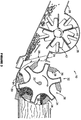
Figure 2 is a schematic sectional view of a portion of the drum and adjacent accelerator wheel for the embodiment of the material reduction machine that is illustrated inFigure 1 , wherein the drum housing is equipped with a first interchangeable belly band that is adapted to provide a smooth inner surface. -
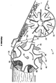
Figure 3 is a schematic sectional view of a portion of the drum and adjacent accelerator wheel for the embodiment of the material reduction machine illustrated inFigures 1 and2 , wherein the drum housing is equipped with a second interchangeable belly band having a plurality of flow interrupters on the inner surface.Figure 3 illustrates a first cutting stage. -
Figure 4 is a schematic sectional view of the portion of the drum and adjacent accelerator wheel that is illustrated inFigure 3 , showing a second cutting stage. -
Figure 5 is a perspective view of a first embodiment of a gauging assembly that comprises a part of the invention. -
Figure 6 is a lower perspective view of a second embodiment of a gauging assembly and an adjustable belly band that comprises a part of a preferred embodiment of the invention. -
Figure 7 is a schematic sectional view of a portion of an alternative embodiment of a material reduction machine showing a gauging assembly and adjustable belly band. - The invention comprises a material reduction machine such as a drum-type wood chipper. As shown in
Figure 1 ,preferred wood chipper 10 includestrailer 12 that is adapted to be pulled by a tractor or other vehicle.Trailer 12 includesframe 14 that is supported bywheels 16 and a pair of adjustable support legs, one of which,support leg 18, is shown inFigure 1 . Supported onframe 14 are feedchute 20, drumhousing 22, intermediate housing 24 (best shown inFigures 2-4 ),accelerator wheel housing 26 anddischarge chute 28.Intermediate housing 24 is located downstream ofdrum housing 22, andaccelerator wheel housing 26 is located downstream ofintermediate housing 24. - Mounted for rotation on shaft 30 (in the clockwise direction, as shown in
Figures 2-4 ) isdrum 32 which includescircumferential wall 34 defining its outer periphery. A plurality ofpockets 36 are spaced around the drum and formed in the circumferential wall, and a plurality ofconventional knives 38, each of which has aleading edge 39 are provided. Aknife 38 is mounted on each of the pockets so that asdrum 32 rotates, the leadingedges 39 of the plurality ofknives 38 cut an arc that is concentric with and of a larger diameter than the circumferential wall of the drum, as can be seen by viewing the right side ofFigure 2 where a leading edge of one of the knives cuts into the wood offeed stock 40. - A driver, such as
engine 41, is also mounted on the frame and adapted to provide a rotational force to drum 32 within the drum housing by means of one or more drive belts or other conventional drive transfer mechanisms (not shown).Engine 41 is also adapted to provide a rotational force toaccelerator wheel 42, which is provided with a plurality ofblades 44, by means of one or more drive belts or other conventional drive transfer mechanisms (riot shown). As shown inFigures 2-4 , the accelerator wheel rotates in the same direction asdrum 32 to increase the momentum of reduced material fromdrum 32. Thus, material to be reduced bymaterial reduction machine 10 is directed into the drum housing fromfeed chute 20 and the reduced material is discharged throughdischarge chute 28 indischarge direction 46. -
Machine 10 is provided with a plurality of interchangeable belly bands, each of which is adapted to be removably attached to the frame so as to form a portion of the drum housing and to provide an inner surface that forms a belly band arc portion that is concentric with and of a larger diameter than the circumferential wall of the drum. These interchangeable belly bands include first interchangeable belly band 49 having a smooth inner surface (shown in.Figure 2 ) and secondinterchangeable belly band 50 having a plurality of flow interrupters spaced along its inner surface, such asflow interrupters 52 shown inFigures 3 and4 . As shown inFigures 2-4 , the belly band arc portion formed by each belly band is adjacent to a portion of the arc cut by the leading edges of the knives. - Preferably, each of
flow interrupters 52 comprises abrasion-resistant material in the form of a bar having a sharp leading edge that is mounted on the inner surface of the secondinterchangeable belly band 50 and extends across the width ofdrum housing 22. As shown inFigure 3 , the leading edges offlow interrupters 52 define anarc 54 that is concentric with and of a different diameter than the belly band arc portion. In alternative embodiments of the invention, the flow interrupters may comprise discrete elements arranged in a matrix, or they may be rounded, or they may comprise minimal projections from, or depressions in, the inside surface of the belly band. The flow interrupters are adapted to reduce the size of the longer, more irregular chips cut from the lower portion of feed stock 40 (as shown inFigures 2-4 ), and the dimensions, number and spacing of the flow interrupters are selected.in order to maximize the production of the desired sized chip. - It is also preferred that a gauging assembly, such as first gauging assembly 56 (shown in
Figures 2-5 ) or second gauging assembly 58 (shown inFigure 6 ) or third gauging assembly 60 (shown inFigure 7 ) be located in an intermediate housing that is downstream of and adjacent to the drum. Each gauging assembly comprises a plurality of flow diverters that are spaced across the width of the drum so as to provide a plurality of sized openings through which reduced material from the drum may pass. Thus, as shown inFigure 5 , gaugingassembly 56 comprises a plurality of generallyupright plates 62 that are mounted tobase 64 and supported by spacingplates upright plates 46 are spaced apart across the width of intermediate housing 24 (and across the width of drum 32) betweendrum housing 22 anddischarge chute 26 so as to provide, in cooperation withspacing plates upright plates 62 has a front side that is curved to form an arc. AlthoughFigure 5 illustrates gaugingassembly 56 as being comprised ofplates Figure 5 shows the gauging assembly as including ten generally upright plates and two spacing plates, different numbers of generally upright plates and spacing members may alternatively be provided. Thus, for example, as shown inFigure 6 , gaugingassembly 58 includes fourteen generallyupright plates 70 that are mounted tobase plate 72 andsupported.by spacing plates upright plates 70 are adapted to be spaced apart across the width of the intermediate housing (and across the width of the drum) between the drum housing and discharge chute so as to provide, in cooperation withspacing plates upright plates 70 has a front side that is curved to form an arc. Gaugingassembly 60, shown inFigure 7 , is of a construction similar to that of gaugingassemblies - Preferably, the gauging assembly is mounted with respect to the frame so as to be adjustable with respect thereto and/or with respect to the circumferential wall of the drum. It is also preferred that each of the plurality of interchangeable belly bands is adapted to be adjustably attached to the frame. Referring again to
Figure 6 , gaugingassembly 58 includes a pair of side supports 80 that are welded or otherwise attached tobase plate 72. Gaugingassembly 58 is adapted to be attached to the frame of the material reduction machine by means of bolts (such as bolts 82) that are passed through generally vertically orientedslots 84 in side supports 80.Base plate 72 has afront end portion 86 that has a plurality of generally horizontally orientedslots 88 spaced across its width. - Located on the downstream end of
belly band assembly 89 isrear support 90, the lower side of which is provided with a plurality of holes (not shown) that are spaced across the width of the belly band assembly and adapted to align withslots 88 so as to permit generally horizontal adjustment of the gauging assembly with respect to the belly band assembly.Belly band assembly 89 also includes a pair of side supports 92, and each of the side supports includes a plurality ofparallel slots 94. Eachparallel slot 94 is adapted to be aligned with a hole (not shown) in the frame, so that a bolt place through the hole in the frame and through the slot may be tightened in a plurality of positions along the slot. Thus,belly band assembly 89 is adapted to be attached to the frame so as to be vertically adjustable with respect thereto. Furthermore, the cooperation ofslots 88 infront end portion 86 ofbase plate 72 and the adjacent aligned holes in the lower side ofrear support 90 of the belly band, and the cooperation ofslots 94 in side supports 92 ofbelly band assembly 92 and the adjacent aligned holes in the frame (not shown), and the cooperation ofslots 84 in side supports 80 of gaugingassembly 58 with adjacent aligned holes in the frame (not shown) will allow for adjustment of the gauging assembly with respect to the circumferential wall of the drum. Other arrangements of slots, holes and other features and mechanisms known to those having ordinary skill in the art to which the invention relates may be provided to allow for adjustment of the belly band with respect to the frame, and/or to allow for adjustment of the gauging assembly with respect to the frame, and/or to allow for adjustment of the gauging assembly with respect to the belly band and/or the circumferential wall of the drum. -
Figure 7 showsmaterial reduction machine 110, which is similar tomaterial reduction machine 10, but does not include an accelerator wheel. Mounted for rotation aboutshaft 130 ofmachine 110 isdrum 132, which includescircumferential wall 134 and pockets 136.Knives 138 are mounted on the drum with respect to the circumferential wall so that as the drum rotates, the leading edges of the knives cut an arc that is concentric with and of a larger diameter than the circumferential wall of the drum.Machine 110 also includes a plurality of interchangeable belly bands, includingbelly band assembly 148, which is adjustable with respect to the frame in the same manner asbelly band assembly 89 ofFigure 6 . In addition,machine 110 includes gaugingassembly 60, which is ajustable with respect to the frame and/or with respect to the circumferential wall of the drum. - Referring again to
Figures 2-4 , it can be seen that asdrum 32 rotates so that leadingedges 39 ofknives 38 cut into the wood offeed stock 40, chips cut by each knife enter the pocket associated with the knife. The wood chips in each pocket remain in the pocket until the drum rotates to align the pocket withintermediate housing 24, which includes gaugingassembly 56. Whendrum 32 is rotated in the clockwise direction, as viewed inFigure 2 , leadingedges 39 ofknives 38 will first pass acrosstop portion 96 of the wood offeed stock 40. As the knives continue to cut to the three o'clock position of the drum, the knives pass across the feed stock in a direction that is perpendicular to the direction of the grain. As the drum continues to rotate so that the knives cut the feed stock nearer the six o'clock position of the drum, the knives pass across the feed stock in a path that is more parallel to the direction of the grain. Because the cutting path angle relative to the direction of the grain varies in this manner, the chips break from the feed stock differently, with the chips from the lower portion (as viewed inFigure 2 ) tending to be longer and more irregular in size. - When it is desirable to produce chips of a more uniform size, the smooth-surfaced
belly band 48 shown inFigure 2 may be replaced withbelly band 50 shown inFigures 3 and4 . Whendrum 32 is rotated in the clockwise direction, as viewed inFigures 3 and4 , leadingedges 39 ofknives 38 will first pass acrosstop portion 96 of the wood offeed stock 40. The knives pass across the feed stock in a direction that is perpendicular to the direction of the grain, thus producing uniformly sized chips. As the knives continue to cut to the three o'clock position of the drum, the knives continue to produce uniformly sized chips that partially fill the associated pockets. As the drum continues to rotate so that the knives cut the feed stock nearer the six o'clock position of the drum, the knives pass across the feed stock in a path that is more parallel to the direction of the grain. Because the cutting path angle relative to the direction of the grain varies in this manner, the chips break from the feed stock differently, with the chips cut from the lower portion of the feed stock (as viewed inFigures 3 and4 ) tending to be longer and more irregular in size. These chips are collected in the radially-outer part of the associated pocket. As the drum continues to rotate, the collected chips pass across theflow interrupters 52, where the irregularly sized chips in the pocket are repeatedly impacted by the flow interrupters and/or the knives and are further reduced. As the drum continues to rotate, the pocket will align with.intermediate housing 24 which includes gaugingassembly 56. The chips pass out ofpocket 36 and pass through the gauging assembly intoaccelerator wheel housing 26.Accelerator wheel 42 is adapted to be rotated in a direction that is selected to increase the momentum of the chips passing through gaugingassembly 56 and intodischarge chute 28. - Although this description contains many specifics, these should not be construed as limiting the scope of the invention, but as merely providing illustrations of the presently preferred embodiment thereof, as well as the best mode contemplated by the inventors of carrying out the invention. The invention, as described herein, is susceptible to various modifications and adaptations, as would be understood by those having ordinary skill in the art to which the invention relates, and the same are intended to be comprehended within the meaning and range of equivalents of the appended claims.
- According to one aspect, the present invention comprises a material reduction machine comprising:
- (a) a frame;
- (b) a drum housing mounted to the frame;
- (c) a drum that is mounted for rotation within the drum housing, said drum comprising:
- (i) a circumferential wall;
- (iii) a plurality of pockets spaced around and formed in the circumferential wall;
- (ii) a plurality of knives, each of which has a leading edge and each of which is mounted on one of the pockets so that as the drum rotates, the leading edges of the plurality of knives cut an arc that is concentric with and of a larger diameter than the circumferential wall of the drum;
- (d) means for rotating the drum within the drum housing;
- (e) a feed chute for directing material to be reduced into the drum housing;
- (f) an intermediate housing that is located downstream of and adjacent to the drum housing;
- (g) a gauging assembly that is mounted in the intermediate housing adjacent to the drum, said gauging assembly comprising a plurality of flow diverters that are spaced across the width of the intermediate housing so as to provide a plurality of sized openings through which reduced material from the drum may pass;
- (h) a discharge chute for directing reduced material away from the drum housing;
- (i) a plurality of interchangeable belly bands, each of which is adapted to be removably attached to the frame so as to form a portion of the drum housing and to provide an inner surface that forms a belly band arc portion that is concentric with and of a larger diameter than the circumferential wall of the drum, said belly band arc portion being adjacent to a portion of the arc cut by the leading edges of the plurality of knives, wherein the plurality of interchangeable belly bands comprises:
- (i) a first interchangeable belly band having a smooth inner surface;
- (ii) a second interchangeable belly band having a plurality of flow interrupters spaced along its inner surface, said plurality of flow interrupters defining an arc that is concentric with and of a different diameter than the belly band arc portion.
- The material reduction machine may include:
- (a) an accelerator wheel housing that is located downstream of and adjacent to the intermediate housing;
- (b) an accelerator wheel that is mounted in the accelerator wheel housing and adapted to be rotated in the same direction as the drum to increase the momentum of the reduced material from the drum;
- (c) means for rotating the accelerator wheel within the accelerator wheel housing.
- Each of the plurality of flow interrupters may comprise a bar having a sharp leading edge that is mounted on the inner surface of the second interchangeable belly band.
- The gauging assembly may be mounted to the frame so as to be adjustable with respect thereto.
- Each of the plurality of interchangeable belly bands may be adapted to be adjustably attached to the frame.
Claims (15)
- A material reduction machine (10) comprising:(a) a frame (14);(b) a drum housing (22) mounted to the frame (14);(c) a drum (32) that is mounted for rotation within the drum housing (22), said drum (32) comprising:(i) a circumferential wall (34);(ii) a knife (38) having a leading edge (39), said knife (38) being mounted on the drum (32) with respect to the circumferential wall (34) so that as the drum (32) rotates, the leading edge (39) of the knife (38) cuts an arc that is concentric with and of a larger diameter than the circumferential wall (34) of the drum (32);(d) means (41) for rotating the drum (32) within the drum housing (22);(e) a feed chute (20) for directing material to be reduced into the drum housing (22); and(f) a discharge chute (28) for directing reduced material away from the drum housing (22);
characterized in that said machine (10) also includes:(g) a plurality of interchangeable belly bands, each of which is adapted to be removably attached to the frame (14) so as to form a portion of the drum housing (22) and to provide an inner surface that forms a belly band arc portion that is concentric with and of a larger diameter than the circumferential wall (34) of the drum (32), said belly band arc portion being adjacent to a portion of the arc cut by the leading edge (39) of the knife (38), wherein the plurality of interchangeable belly bands comprises:(i) a first interchangeable belly band (48) having a smooth inner surface;(ii) a second interchangeable belly band (50) having a plurality of flow interrupters (52) spaced along its inner surface. - The material reduction machine of claim 1, wherein the circumferential wall (34) of the drum (32) is provided with a pocket (36), and the knife (38) is mounted on the pocket (36) in such a way that as the drum (32) rotates, the leading edge (39) of the knife (38) cuts an arc that is concentric with and of a larger diameter than the circumferential wall (34) of the drum (32).
- The material reduction machine of claim 1, wherein the drum (32) comprises a plurality of pockets (36) spaced around the circumferential wall (34) of the drum (32) with a knife (38) mounted on each pocket (36) in such a way that as the drum (32) rotates, the leading edges (39) of the knives (38) cut an arc that is concentric with and of a larger diameter than the circumferential wall (34) of the drum (32).
- The material reduction machine of claim 1,2 or 3, wherein the plurality of flow interrupters (52) define an arc that is concentric with and of a different diameter than the belly band arc portion.
- The material reduction machine of claim 1,2,3 or 4, wherein each of the plurality of flow interrupters (52) comprises a bar having a sharp leading edge that is mounted on the inner surface of the second interchangeable belly band (50).
- The material reduction machine of any preceding claim, comprising:(a) an accelerator wheel (42) that is mounted for rotation in that same direction as the drum (32) and is located downstream of the drum (32), said accelerator wheel (42) being adapted to increase the momentum of the reduced material from the drum (32);(b) means (41) for rotating the accelerator wheel.
- The material reduction machine of any preceding claim, wherein each of the plurality of interchangeable belly bands is adapted to be adjustably attached to the frame (14).
- The material reduction machine of claim 7, wherein each of the plurality of interchangeable belly bands is adapted to be attached to the frame (14) so as to be generally vertically adjustable with respect thereto.
- The material reduction machine of any preceding claim, which includes a gauging assembly (56) that is located downstream of and adjacent to the drum (32), said gauging assembly (56) comprising a plurality of flow diverters (46, 62) that are spaced across the width of the drum (32) so as to provide a plurality of sized openings through which reduced material from the drum (32) may pass.
- The material reduction machine of claim 9, wherein the gauging assembly (56) is mounted so as to be horizontally adjustable with respect to the frame (14).
- The material reduction machine of claim 9 or 10, wherein at least a portion of the plurality of flow diverters (62) has a front side that is curved to form an arc.
- The material reduction machine of claim 9, 10 or 11, wherein the gauging assembly (56) is mounted so as to be adjustable with respect to the circumferential wall (34) of the drum (32).
- The material reduction machine of any one of claims 1 to 8, comprising a gauging assembly (56) which includes a plurality of flow diverters (46, 62) that are spaced across the width of the drum (32) so as to provide a plurality of sized openings through which reduced material from the drum (32) may pass, said gauging assembly (56) being adapted for generally horizontally adjustable attachment to each of the interchangeable belly bands.
- The material reduction machine of any preceding claim, wherein:(a) each of the interchangeable belly bands includes a pair of side supports (92);(b) each of the side supports (92) includes a plurality of parallel slots (94), each of which is adapted to be aligned with a hole in the frame (14), so that a bolt placed through the hole in the frame (14) and through the slot (94) may be tightened in a plurality of positions along the slot (94).
- The material reduction machine of claim 14:(a) wherein the downstream end of each of the interchangeable belly bands includes a rear support (90) having a plurality of holes spaced across the width of the belly band;(b) which includes a gauging assembly (58) that is located downstream of and adjacent to the drum (32), said gauging assembly (58) comprising:(i) a base plate (72) including a plurality of slots (88) that are spaced across the width of the base plate (72), each of said slots (88) being adapted to be aligned with a hole in the rear support (90) of each of the interchangeable belly bands;(ii) a plurality of flow diverters (70) that are mounted on the base plate (72) and spaced across the width thereof.
Applications Claiming Priority (2)
| Application Number | Priority Date | Filing Date | Title |
|---|---|---|---|
| US201161571873P | 2011-07-07 | 2011-07-07 | |
| PCT/US2012/042896 WO2013006258A1 (en) | 2011-07-07 | 2012-06-18 | Material reduction machine |
Publications (3)
| Publication Number | Publication Date |
|---|---|
| EP2729255A1 EP2729255A1 (en) | 2014-05-14 |
| EP2729255A4 EP2729255A4 (en) | 2015-04-22 |
| EP2729255B1 true EP2729255B1 (en) | 2016-04-20 |
Family
ID=47437352
Family Applications (1)
| Application Number | Title | Priority Date | Filing Date |
|---|---|---|---|
| EP12806943.2A Active EP2729255B1 (en) | 2011-07-07 | 2012-06-18 | Material reduction machine |
Country Status (4)
| Country | Link |
|---|---|
| US (1) | US8783593B2 (en) |
| EP (1) | EP2729255B1 (en) |
| CA (1) | CA2840722C (en) |
| WO (1) | WO2013006258A1 (en) |
Families Citing this family (6)
| Publication number | Priority date | Publication date | Assignee | Title |
|---|---|---|---|---|
| CA2986995C (en) * | 2010-02-15 | 2021-01-19 | Certainteed Corporation | System, method and apparatus for processing fiber materials |
| WO2016101039A1 (en) * | 2014-12-23 | 2016-06-30 | Bionic Beaver Pty Ltd | Mass flow device for chipping machines |
| US20160263582A1 (en) * | 2015-03-10 | 2016-09-15 | Astec Industries, Inc. | Material reduction machine with adjustable discharge air flow control |
| WO2017040069A1 (en) * | 2015-09-02 | 2017-03-09 | Astec Industries, Inc. | Chip size control system for log chipping machine |
| NO345925B1 (en) | 2017-08-16 | 2021-10-25 | Arbaflame Tech As | Method and apparatus for production of cellulose based fuel pellets. |
| US12521728B1 (en) * | 2023-05-26 | 2026-01-13 | James R. Fincher Timber Co., Inc. | Conveyor drum chipper with screen |
Family Cites Families (14)
| Publication number | Priority date | Publication date | Assignee | Title |
|---|---|---|---|---|
| US2420670A (en) * | 1944-02-23 | 1947-05-20 | Birtman Electric Co | Disintegrator screen |
| US4383652A (en) * | 1981-04-20 | 1983-05-17 | Sperry Corporation | Shredbar apparatus |
| US5005620A (en) | 1990-04-17 | 1991-04-09 | Morbark Industries, Inc. | Drum-type wood chipper |
| US5413286A (en) | 1992-04-27 | 1995-05-09 | Tramor, Inc. | Waste processing machine |
| US5390862A (en) | 1992-06-12 | 1995-02-21 | 7/7/77 Incorporated | Apparatus for chipping and grinding tree limbs |
| US5381971A (en) * | 1993-07-09 | 1995-01-17 | Williams Patent Crusher And Pulverizer Company | Grinding apparatus |
| US5526988A (en) * | 1994-11-29 | 1996-06-18 | Rine; James | Comminuting apparatus with tangentially directed discharge |
| US5692548A (en) | 1996-05-17 | 1997-12-02 | Vermeer Manufacturing Company | Wood chipper |
| US5692549A (en) | 1996-05-17 | 1997-12-02 | Vermeer Manufacturing Company | Feed rollers for chipper |
| US5819825A (en) | 1997-05-27 | 1998-10-13 | West Salem Machinery | Interchangeable chipper attachment for a hog |
| US6032707A (en) | 1998-12-22 | 2000-03-07 | Tramor, Inc. | Drum assembly for a wood chipper |
| US6016855A (en) | 1999-03-04 | 2000-01-25 | Tramor, Inc. | Hood assembly for a wood chipper |
| EP1201311A1 (en) * | 2000-10-26 | 2002-05-02 | SATRIND S.r.l. | Rotary blade shredding apparatus |
| JP4859969B2 (en) * | 2009-09-11 | 2012-01-25 | 株式会社奈良機械製作所 | Powder and granulator |
-
2012
- 2012-06-07 US US13/491,344 patent/US8783593B2/en active Active
- 2012-06-18 CA CA2840722A patent/CA2840722C/en active Active
- 2012-06-18 EP EP12806943.2A patent/EP2729255B1/en active Active
- 2012-06-18 WO PCT/US2012/042896 patent/WO2013006258A1/en not_active Ceased
Also Published As
| Publication number | Publication date |
|---|---|
| WO2013006258A1 (en) | 2013-01-10 |
| US8783593B2 (en) | 2014-07-22 |
| CA2840722C (en) | 2015-10-13 |
| EP2729255A1 (en) | 2014-05-14 |
| CA2840722A1 (en) | 2013-01-10 |
| US20130008987A1 (en) | 2013-01-10 |
| EP2729255A4 (en) | 2015-04-22 |
Similar Documents
| Publication | Publication Date | Title |
|---|---|---|
| US8783593B2 (en) | Material reduction machine | |
| EP3143866B1 (en) | A system for chopping and spreading residue | |
| CN203408743U (en) | Shredding components and shredders | |
| CN101980788B (en) | Self-contained shredder assembly for reducing and sizing material | |
| US6032707A (en) | Drum assembly for a wood chipper | |
| EP1542526A1 (en) | Apparatus for chopping and discharging straw from a combine harvester | |
| US20100294868A1 (en) | Chipper drum with integral blower | |
| WO2023004494A1 (en) | Weed seed destruction | |
| JP2018000189A (en) | Combine | |
| US5873397A (en) | Wood pulverizer with improved hammers and anvils | |
| CN112702906A (en) | Combine harvester | |
| EP0959659A1 (en) | Arrangement in cutting machine | |
| US9308533B2 (en) | Shredder with side discharge | |
| US20060006266A1 (en) | Bale processor with feed cutter | |
| EP2818248A1 (en) | Rotary tool for cutting materials and cutting machine comprising such a rotary tool | |
| CN110278784A (en) | A kind of more crop straw crushers of shock resistance and method | |
| US9370776B2 (en) | Mounting block for attaching a reducing element to a rotary drum | |
| CN210900438U (en) | Bract recovery device for harvesting bract rice | |
| EP2650050B1 (en) | Wood chipping machine with peripheral sieving and disintegration device | |
| US20160263582A1 (en) | Material reduction machine with adjustable discharge air flow control | |
| CN215774375U (en) | Integrated machine for cutting grass, kneading silk and crushing particles | |
| CN208273661U (en) | A kind of stalk crasher | |
| CA2339437C (en) | Apparatus for chopping and discharging straw from a combine harvester | |
| CN206652569U (en) | A kind of chopping guider for obstructing leaf seperator | |
| JPH01135547A (en) | Material processing and treatment apparatus |
Legal Events
| Date | Code | Title | Description |
|---|---|---|---|
| PUAI | Public reference made under article 153(3) epc to a published international application that has entered the european phase |
Free format text: ORIGINAL CODE: 0009012 |
|
| 17P | Request for examination filed |
Effective date: 20140106 |
|
| AK | Designated contracting states |
Kind code of ref document: A1 Designated state(s): AL AT BE BG CH CY CZ DE DK EE ES FI FR GB GR HR HU IE IS IT LI LT LU LV MC MK MT NL NO PL PT RO RS SE SI SK SM TR |
|
| RAP1 | Party data changed (applicant data changed or rights of an application transferred) |
Owner name: ASTEC INDUSTRIES, INC. |
|
| DAX | Request for extension of the european patent (deleted) | ||
| RA4 | Supplementary search report drawn up and despatched (corrected) |
Effective date: 20150324 |
|
| RIC1 | Information provided on ipc code assigned before grant |
Ipc: B02C 18/18 20060101AFI20150318BHEP |
|
| GRAP | Despatch of communication of intention to grant a patent |
Free format text: ORIGINAL CODE: EPIDOSNIGR1 |
|
| INTG | Intention to grant announced |
Effective date: 20151030 |
|
| GRAS | Grant fee paid |
Free format text: ORIGINAL CODE: EPIDOSNIGR3 |
|
| GRAA | (expected) grant |
Free format text: ORIGINAL CODE: 0009210 |
|
| AK | Designated contracting states |
Kind code of ref document: B1 Designated state(s): AL AT BE BG CH CY CZ DE DK EE ES FI FR GB GR HR HU IE IS IT LI LT LU LV MC MK MT NL NO PL PT RO RS SE SI SK SM TR |
|
| REG | Reference to a national code |
Ref country code: GB Ref legal event code: FG4D |
|
| REG | Reference to a national code |
Ref country code: CH Ref legal event code: EP |
|
| REG | Reference to a national code |
Ref country code: AT Ref legal event code: REF Ref document number: 791805 Country of ref document: AT Kind code of ref document: T Effective date: 20160515 |
|
| REG | Reference to a national code |
Ref country code: IE Ref legal event code: FG4D |
|
| REG | Reference to a national code |
Ref country code: DE Ref legal event code: R096 Ref document number: 602012017441 Country of ref document: DE |
|
| REG | Reference to a national code |
Ref country code: FR Ref legal event code: PLFP Year of fee payment: 5 |
|
| REG | Reference to a national code |
Ref country code: SE Ref legal event code: TRGR |
|
| REG | Reference to a national code |
Ref country code: LT Ref legal event code: MG4D |
|
| REG | Reference to a national code |
Ref country code: AT Ref legal event code: MK05 Ref document number: 791805 Country of ref document: AT Kind code of ref document: T Effective date: 20160420 |
|
| REG | Reference to a national code |
Ref country code: NL Ref legal event code: MP Effective date: 20160420 |
|
| PG25 | Lapsed in a contracting state [announced via postgrant information from national office to epo] |
Ref country code: NO Free format text: LAPSE BECAUSE OF FAILURE TO SUBMIT A TRANSLATION OF THE DESCRIPTION OR TO PAY THE FEE WITHIN THE PRESCRIBED TIME-LIMIT Effective date: 20160720 Ref country code: PL Free format text: LAPSE BECAUSE OF FAILURE TO SUBMIT A TRANSLATION OF THE DESCRIPTION OR TO PAY THE FEE WITHIN THE PRESCRIBED TIME-LIMIT Effective date: 20160420 Ref country code: NL Free format text: LAPSE BECAUSE OF FAILURE TO SUBMIT A TRANSLATION OF THE DESCRIPTION OR TO PAY THE FEE WITHIN THE PRESCRIBED TIME-LIMIT Effective date: 20160420 Ref country code: LT Free format text: LAPSE BECAUSE OF FAILURE TO SUBMIT A TRANSLATION OF THE DESCRIPTION OR TO PAY THE FEE WITHIN THE PRESCRIBED TIME-LIMIT Effective date: 20160420 |
|
| PG25 | Lapsed in a contracting state [announced via postgrant information from national office to epo] |
Ref country code: ES Free format text: LAPSE BECAUSE OF FAILURE TO SUBMIT A TRANSLATION OF THE DESCRIPTION OR TO PAY THE FEE WITHIN THE PRESCRIBED TIME-LIMIT Effective date: 20160420 Ref country code: GR Free format text: LAPSE BECAUSE OF FAILURE TO SUBMIT A TRANSLATION OF THE DESCRIPTION OR TO PAY THE FEE WITHIN THE PRESCRIBED TIME-LIMIT Effective date: 20160721 Ref country code: LV Free format text: LAPSE BECAUSE OF FAILURE TO SUBMIT A TRANSLATION OF THE DESCRIPTION OR TO PAY THE FEE WITHIN THE PRESCRIBED TIME-LIMIT Effective date: 20160420 Ref country code: PT Free format text: LAPSE BECAUSE OF FAILURE TO SUBMIT A TRANSLATION OF THE DESCRIPTION OR TO PAY THE FEE WITHIN THE PRESCRIBED TIME-LIMIT Effective date: 20160822 Ref country code: AT Free format text: LAPSE BECAUSE OF FAILURE TO SUBMIT A TRANSLATION OF THE DESCRIPTION OR TO PAY THE FEE WITHIN THE PRESCRIBED TIME-LIMIT Effective date: 20160420 Ref country code: RS Free format text: LAPSE BECAUSE OF FAILURE TO SUBMIT A TRANSLATION OF THE DESCRIPTION OR TO PAY THE FEE WITHIN THE PRESCRIBED TIME-LIMIT Effective date: 20160420 Ref country code: HR Free format text: LAPSE BECAUSE OF FAILURE TO SUBMIT A TRANSLATION OF THE DESCRIPTION OR TO PAY THE FEE WITHIN THE PRESCRIBED TIME-LIMIT Effective date: 20160420 |
|
| PG25 | Lapsed in a contracting state [announced via postgrant information from national office to epo] |
Ref country code: BE Free format text: LAPSE BECAUSE OF FAILURE TO SUBMIT A TRANSLATION OF THE DESCRIPTION OR TO PAY THE FEE WITHIN THE PRESCRIBED TIME-LIMIT Effective date: 20160420 Ref country code: IT Free format text: LAPSE BECAUSE OF FAILURE TO SUBMIT A TRANSLATION OF THE DESCRIPTION OR TO PAY THE FEE WITHIN THE PRESCRIBED TIME-LIMIT Effective date: 20160420 |
|
| REG | Reference to a national code |
Ref country code: DE Ref legal event code: R097 Ref document number: 602012017441 Country of ref document: DE |
|
| PG25 | Lapsed in a contracting state [announced via postgrant information from national office to epo] |
Ref country code: EE Free format text: LAPSE BECAUSE OF FAILURE TO SUBMIT A TRANSLATION OF THE DESCRIPTION OR TO PAY THE FEE WITHIN THE PRESCRIBED TIME-LIMIT Effective date: 20160420 Ref country code: RO Free format text: LAPSE BECAUSE OF FAILURE TO SUBMIT A TRANSLATION OF THE DESCRIPTION OR TO PAY THE FEE WITHIN THE PRESCRIBED TIME-LIMIT Effective date: 20160420 Ref country code: CZ Free format text: LAPSE BECAUSE OF FAILURE TO SUBMIT A TRANSLATION OF THE DESCRIPTION OR TO PAY THE FEE WITHIN THE PRESCRIBED TIME-LIMIT Effective date: 20160420 Ref country code: MC Free format text: LAPSE BECAUSE OF FAILURE TO SUBMIT A TRANSLATION OF THE DESCRIPTION OR TO PAY THE FEE WITHIN THE PRESCRIBED TIME-LIMIT Effective date: 20160420 Ref country code: DK Free format text: LAPSE BECAUSE OF FAILURE TO SUBMIT A TRANSLATION OF THE DESCRIPTION OR TO PAY THE FEE WITHIN THE PRESCRIBED TIME-LIMIT Effective date: 20160420 Ref country code: SK Free format text: LAPSE BECAUSE OF FAILURE TO SUBMIT A TRANSLATION OF THE DESCRIPTION OR TO PAY THE FEE WITHIN THE PRESCRIBED TIME-LIMIT Effective date: 20160420 |
|
| REG | Reference to a national code |
Ref country code: CH Ref legal event code: PL |
|
| PLBE | No opposition filed within time limit |
Free format text: ORIGINAL CODE: 0009261 |
|
| STAA | Information on the status of an ep patent application or granted ep patent |
Free format text: STATUS: NO OPPOSITION FILED WITHIN TIME LIMIT |
|
| PG25 | Lapsed in a contracting state [announced via postgrant information from national office to epo] |
Ref country code: SM Free format text: LAPSE BECAUSE OF FAILURE TO SUBMIT A TRANSLATION OF THE DESCRIPTION OR TO PAY THE FEE WITHIN THE PRESCRIBED TIME-LIMIT Effective date: 20160420 |
|
| REG | Reference to a national code |
Ref country code: IE Ref legal event code: MM4A |
|
| 26N | No opposition filed |
Effective date: 20170123 |
|
| PG25 | Lapsed in a contracting state [announced via postgrant information from national office to epo] |
Ref country code: CH Free format text: LAPSE BECAUSE OF NON-PAYMENT OF DUE FEES Effective date: 20160630 Ref country code: LI Free format text: LAPSE BECAUSE OF NON-PAYMENT OF DUE FEES Effective date: 20160630 |
|
| PG25 | Lapsed in a contracting state [announced via postgrant information from national office to epo] |
Ref country code: SI Free format text: LAPSE BECAUSE OF FAILURE TO SUBMIT A TRANSLATION OF THE DESCRIPTION OR TO PAY THE FEE WITHIN THE PRESCRIBED TIME-LIMIT Effective date: 20160420 Ref country code: IE Free format text: LAPSE BECAUSE OF NON-PAYMENT OF DUE FEES Effective date: 20160618 |
|
| REG | Reference to a national code |
Ref country code: FR Ref legal event code: PLFP Year of fee payment: 6 |
|
| PG25 | Lapsed in a contracting state [announced via postgrant information from national office to epo] |
Ref country code: HU Free format text: LAPSE BECAUSE OF FAILURE TO SUBMIT A TRANSLATION OF THE DESCRIPTION OR TO PAY THE FEE WITHIN THE PRESCRIBED TIME-LIMIT; INVALID AB INITIO Effective date: 20120618 |
|
| REG | Reference to a national code |
Ref country code: FR Ref legal event code: PLFP Year of fee payment: 7 |
|
| PG25 | Lapsed in a contracting state [announced via postgrant information from national office to epo] |
Ref country code: MT Free format text: LAPSE BECAUSE OF NON-PAYMENT OF DUE FEES Effective date: 20160630 Ref country code: CY Free format text: LAPSE BECAUSE OF FAILURE TO SUBMIT A TRANSLATION OF THE DESCRIPTION OR TO PAY THE FEE WITHIN THE PRESCRIBED TIME-LIMIT Effective date: 20160420 Ref country code: MK Free format text: LAPSE BECAUSE OF FAILURE TO SUBMIT A TRANSLATION OF THE DESCRIPTION OR TO PAY THE FEE WITHIN THE PRESCRIBED TIME-LIMIT Effective date: 20160420 Ref country code: LU Free format text: LAPSE BECAUSE OF NON-PAYMENT OF DUE FEES Effective date: 20160618 Ref country code: IS Free format text: LAPSE BECAUSE OF FAILURE TO SUBMIT A TRANSLATION OF THE DESCRIPTION OR TO PAY THE FEE WITHIN THE PRESCRIBED TIME-LIMIT Effective date: 20160420 |
|
| PG25 | Lapsed in a contracting state [announced via postgrant information from national office to epo] |
Ref country code: BG Free format text: LAPSE BECAUSE OF FAILURE TO SUBMIT A TRANSLATION OF THE DESCRIPTION OR TO PAY THE FEE WITHIN THE PRESCRIBED TIME-LIMIT Effective date: 20160420 |
|
| PG25 | Lapsed in a contracting state [announced via postgrant information from national office to epo] |
Ref country code: TR Free format text: LAPSE BECAUSE OF FAILURE TO SUBMIT A TRANSLATION OF THE DESCRIPTION OR TO PAY THE FEE WITHIN THE PRESCRIBED TIME-LIMIT Effective date: 20160420 Ref country code: AL Free format text: LAPSE BECAUSE OF FAILURE TO SUBMIT A TRANSLATION OF THE DESCRIPTION OR TO PAY THE FEE WITHIN THE PRESCRIBED TIME-LIMIT Effective date: 20160420 |
|
| PGFP | Annual fee paid to national office [announced via postgrant information from national office to epo] |
Ref country code: FI Payment date: 20200618 Year of fee payment: 9 Ref country code: FR Payment date: 20200623 Year of fee payment: 9 |
|
| PGFP | Annual fee paid to national office [announced via postgrant information from national office to epo] |
Ref country code: SE Payment date: 20200625 Year of fee payment: 9 |
|
| REG | Reference to a national code |
Ref country code: FI Ref legal event code: MAE |
|
| REG | Reference to a national code |
Ref country code: SE Ref legal event code: EUG |
|
| PG25 | Lapsed in a contracting state [announced via postgrant information from national office to epo] |
Ref country code: FI Free format text: LAPSE BECAUSE OF NON-PAYMENT OF DUE FEES Effective date: 20210618 |
|
| PG25 | Lapsed in a contracting state [announced via postgrant information from national office to epo] |
Ref country code: FR Free format text: LAPSE BECAUSE OF NON-PAYMENT OF DUE FEES Effective date: 20210630 Ref country code: SE Free format text: LAPSE BECAUSE OF NON-PAYMENT OF DUE FEES Effective date: 20210619 |
|
| P01 | Opt-out of the competence of the unified patent court (upc) registered |
Effective date: 20230526 |
|
| PGFP | Annual fee paid to national office [announced via postgrant information from national office to epo] |
Ref country code: DE Payment date: 20250619 Year of fee payment: 14 |
|
| PGFP | Annual fee paid to national office [announced via postgrant information from national office to epo] |
Ref country code: GB Payment date: 20250608 Year of fee payment: 14 |
|
| REG | Reference to a national code |
Ref country code: DE Ref legal event code: R082 Ref document number: 602012017441 Country of ref document: DE Representative=s name: DR. RIEBLING & PARTNER PATENTANWAELTE MBB, DE |