EP2728779B1 - Data reconstruction method and device - Google Patents
Data reconstruction method and device Download PDFInfo
- Publication number
- EP2728779B1 EP2728779B1 EP12816839.0A EP12816839A EP2728779B1 EP 2728779 B1 EP2728779 B1 EP 2728779B1 EP 12816839 A EP12816839 A EP 12816839A EP 2728779 B1 EP2728779 B1 EP 2728779B1
- Authority
- EP
- European Patent Office
- Prior art keywords
- antenna
- fading
- fading factor
- actual
- auto
- Prior art date
- Legal status (The legal status is an assumption and is not a legal conclusion. Google has not performed a legal analysis and makes no representation as to the accuracy of the status listed.)
- Not-in-force
Links
- 238000000034 method Methods 0.000 title claims description 78
- 238000005562 fading Methods 0.000 claims description 149
- 239000011159 matrix material Substances 0.000 claims description 53
- 238000005311 autocorrelation function Methods 0.000 claims description 46
- 230000008569 process Effects 0.000 claims description 38
- 238000012545 processing Methods 0.000 claims description 33
- 238000000354 decomposition reaction Methods 0.000 claims description 5
- 238000005314 correlation function Methods 0.000 claims 1
- 238000005516 engineering process Methods 0.000 description 8
- 238000010586 diagram Methods 0.000 description 6
- 238000013459 approach Methods 0.000 description 2
- 230000005540 biological transmission Effects 0.000 description 2
- 230000008859 change Effects 0.000 description 2
- 238000004891 communication Methods 0.000 description 2
- 230000008030 elimination Effects 0.000 description 2
- 238000003379 elimination reaction Methods 0.000 description 2
- 230000006872 improvement Effects 0.000 description 2
- 230000004044 response Effects 0.000 description 2
- 102000016550 Complement Factor H Human genes 0.000 description 1
- 108010053085 Complement Factor H Proteins 0.000 description 1
- 238000007476 Maximum Likelihood Methods 0.000 description 1
- 238000010276 construction Methods 0.000 description 1
- 238000001514 detection method Methods 0.000 description 1
- 238000011161 development Methods 0.000 description 1
- 238000012986 modification Methods 0.000 description 1
- 230000004048 modification Effects 0.000 description 1
- 230000003287 optical effect Effects 0.000 description 1
- 238000011160 research Methods 0.000 description 1
- 230000008054 signal transmission Effects 0.000 description 1
Images


Classifications
-
- H—ELECTRICITY
- H04—ELECTRIC COMMUNICATION TECHNIQUE
- H04L—TRANSMISSION OF DIGITAL INFORMATION, e.g. TELEGRAPHIC COMMUNICATION
- H04L25/00—Baseband systems
- H04L25/02—Details ; arrangements for supplying electrical power along data transmission lines
- H04L25/0202—Channel estimation
-
- H—ELECTRICITY
- H04—ELECTRIC COMMUNICATION TECHNIQUE
- H04L—TRANSMISSION OF DIGITAL INFORMATION, e.g. TELEGRAPHIC COMMUNICATION
- H04L25/00—Baseband systems
- H04L25/02—Details ; arrangements for supplying electrical power along data transmission lines
- H04L25/0202—Channel estimation
- H04L25/0212—Channel estimation of impulse response
-
- H—ELECTRICITY
- H04—ELECTRIC COMMUNICATION TECHNIQUE
- H04L—TRANSMISSION OF DIGITAL INFORMATION, e.g. TELEGRAPHIC COMMUNICATION
- H04L25/00—Baseband systems
- H04L25/02—Details ; arrangements for supplying electrical power along data transmission lines
- H04L25/0202—Channel estimation
- H04L25/0224—Channel estimation using sounding signals
-
- H—ELECTRICITY
- H04—ELECTRIC COMMUNICATION TECHNIQUE
- H04L—TRANSMISSION OF DIGITAL INFORMATION, e.g. TELEGRAPHIC COMMUNICATION
- H04L1/00—Arrangements for detecting or preventing errors in the information received
- H04L1/02—Arrangements for detecting or preventing errors in the information received by diversity reception
- H04L1/06—Arrangements for detecting or preventing errors in the information received by diversity reception using space diversity
Definitions
- the present invention relates to the field of communications technologies, and in particular, to a method and an apparatus for reconstructing data.
- an interference cancellation (IC, Interference Cancellation) technology is introduced to improve an uplink data transmission rate.
- This technology reconstructs a received signal according to an estimate value of a user and is used to cancel a signal that interferes with a user, so as to improve a demodulated signal-to-interference-plus-noise ratio, thereby improving performance of a target user.
- the interference cancellation technology reduces uplink interference to obtain performance improvement by cancelling Dedicated Physical Data Channel (DPDCH, Dedicated Physical Data Channel) data, Dedicated Physical Control Channel (DPCCH, Dedicated Physical Control Channel) data, Enhanced Dedicated Physical Control Channel (EDPCCH) data, and Enhanced Dedicated Physical Data Channel (EDPDCH) data of each user in baseband data.
- DPDCH Dedicated Physical Data Channel
- DPCCH Dedicated Physical Control Channel
- EDPCCH Enhanced Dedicated Physical Control Channel
- EDPDCH Enhanced Dedicated Physical Data Channel
- Reconstruction is one of important steps of interference cancellation, and the quality of reconstruction directly determines cancellation efficiency of interference cancellation and system performance.
- One of important steps of baseband data reconstruction is to add fading to a signal.
- a fading factor obtained by channel estimation is used during the adding of fading and is not an actual fading factor.
- an actual fading factor is needed for a process of baseband data reconstruction that is a process of simulating signal transmission.
- a fading factor obtained by actual estimation is affected by root raised cosine filters at a transmit end and a receive end, and is a result of superposing fading factors of all valid paths and not the actual fading factor.
- a process of data passing through a channel is simulated before data is received, and an impact of the channel on the data is simulated by using an estimated fading factor, and then the data is obtained after being processed twice by a root raised cosine filter (or once by a raised cosine filter).
- What is obtained through the channel estimation is a channel fading factor that includes an impact of a filter, that is, convolutions of the actual fading factor and R p .
- a fading factor obtained by the channel estimation is used.
- US2005/0025267A1 discloses many aspects.
- One aspect of the invention is to perform equalization using a sliding window approach.
- a second aspect reuses information derived for each window for use by a subsequent window.
- a third aspect utilizes a discrete Fourier transform based approach for the equalization.
- a fourth aspect relates to handling oversampling of the received signals and channel responses.
- a fifth aspect relates to handling multiple reception antennas.
- a sixth embodiment relates to handling both oversampling and multiple reception antennas.
- EP1158716A2 discloses a MIMO OFDM system which includes a plurality of space-time encoders for encoding respective data blocks with independent space-time codes.
- the transformed data block signals are transmitted by a plurality of transmit antennas and received by a plurality of receive antennas.
- the received data is pre-whitened prior to maximum likelihood detection.
- successive interference cancellation can be used to improve system performance.
- Channel parameter estimation can be enhanced by weighting the channel impulse response estimates based upon a deviation from average.
- Embodiments of the present invention provide a method and an apparatus for reconstructing data, so as to solve a technical problem that data reconstruction does not follow an actual sending process.
- the embodiments which do not fall within the scope of the claims are interpreted as examples.
- one aspect of the present invention provides a method for reconstructing data, including:
- the present invention further provides an apparatus for reconstructing data, including:
- an estimate value of an actual fading factor is used to reconstruct received data, so that a process of performing the interference cancellation for the reconstructed data is closer to an actual sending process and closer to an originally sent signal, thereby improving cancellation efficiency and reducing interference.
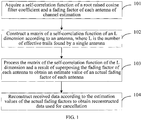
- FIG. 1 is a flowchart of a method for reconstructing data according to an embodiment of the present invention.
- the method includes:
- a root raised cosine filter at a receive end is preset, that is, once the root raised cosine filter at the receive end is determined, an auto-correlation function of the root raised cosine filter at the receive end is determined, and therefore R p is determined.
- a pilot is used by the receive end to perform channel estimation and obtain an estimated fading factor of each antenna, and the channel fading factors obtained by the channel estimation reflect channel information (including an amplitude and a phase).
- channel information including an amplitude and a phase
- Step 102 Construct an L-dimension matrix of the auto-correlation function according to an antenna, where L is the number of valid paths found by the single antenna.
- Step 103 Process the L-dimension matrix of the auto-correlation function and a result of superposing the fading factor of each antenna to obtain an estimate value of an actual fading factor of the each antenna.
- a solving operation may be performed on the matrix of the auto-correlation function and the result of superposing the fading factor of each antenna to obtain the estimate value of the actual fading factor of each antenna.
- the solving operation may specifically be performed according to a method of solving a set of linear equations but is not limited to this, and another algorithm may also be used for the obtaining, which is not limited in this embodiment.
- Step 104 Reconstruct received data according to the estimate value of the actual fading factor to obtain reconstructed data used for cancellation, which is close to actual sent data.
- the reconstructed data is used for interference cancellation, and the reconstructing data is adding fading to the received data.
- the method may further include: reordering locations of the paths and locations of the fading factors according to an antenna number, so that the paths and the fading factors are separately arranged according to different antennas.
- the processing the L-dimension matrix of the auto-correlation function and a result of superposing the fading factor of each antenna to obtain an estimate value of an actual fading factor of each antenna includes: performing inversion on the L-dimension matrix of the auto-correlation function to obtain an L-dimension inverse matrix of the auto-correlation function; performing deconvolution processing on the result of superposing the fading factor of each antenna and the L-dimension inverse matrix of the auto-correlation function to obtain the estimate value of the actual fading factor of each antenna; and then reconstructing the received data according to the estimate values of the actual fading factors to obtain actual sent data.
- the performing inversion on the L-dimension matrix of the auto-correlation function specifically includes: performing inversion on the L-dimension matrix of the auto-correlation function according to a successive over relaxation method (SOR, Successive Over Relaxation Method) or a decomposition method.
- SOR Successive Over Relaxation Method
- decomposition method a successive over relaxation method
- a pilot is used at the receive end to perform channel estimation, and the channel fading factors obtained by the channel estimation reflect channel information (an amplitude and a phase).
- H can be used for all channels with simultaneous transmission, including a data channel.
- Solving a data signal is an inverse process, that is, deriving X from a known H and Y.
- an estimate value Y' of Y is derived according to an estimate value X' of the transmitted data and H.
- actual fading factors are used for adding the fading during the data reconstruction.
- the actual fading factors are obtained through deconvolution of the fading factors obtained by channel estimation and the auto-correlation function R p .
- deconvolution processing needs to be performed, specifically including the following:
- the reverse matrix R pp ⁇ 1 of the matrix R pp is solved.
- this process is already a well-known technology, and therefore no further details are provided herein.
- an estimate value of an actual fading factor is used to reconstruct received data, so that a process of performing the interference cancellation for the reconstructed data is closer to an actual sending process and closer to an originally sent signal, thereby improving cancellation efficiency and reducing interference.
- a signal-to-interference-plus-noise ratio of a user is improved during demodulation and performance is improved; and cell capacity is improved and more users are accessed on a precondition of ensuing that user performance does not change.
- one channel of the data experiences parameter estimation, such as estimation of a path or a fading factor, and an obtained estimation result is used as input of the reconstruction; another channel of data experiences demodulation to obtain information of a transmit end (that is, reconstructed soft information), and the reconstructed soft information is also used as input of the reconstruction; then, reconstruction processing is performed according to the two channels of input to obtain reconstruction of the actual fading factor; and finally, fading is added to the received data by using the actual fading factor to obtain reconstructed data used for cancellation.
- parameter estimation such as estimation of a path or a fading factor
- an obtained estimation result is used as input of the reconstruction
- another channel of data experiences demodulation to obtain information of a transmit end that is, reconstructed soft information
- the reconstructed soft information is also used as input of the reconstruction
- reconstruction processing is performed according to the two channels of input to obtain reconstruction of the actual fading factor
- fading is added to the received data by using the actual fading factor to obtain reconstructed data used for cancellation.
- FIG. 2 is a flowchart of a first application example of a method for reconstructing data according to an embodiment of the present invention.
- a process of deconvolution processing is used as an example to obtain an estimate value of an actual fading factor of each antenna.
- the process specifically includes the following steps:
- a location of a valid path found by the antenna i is tmpFD[Index[i]], and Ni represents the number of valid paths of the antenna i.
- R pp is constructed.
- the matrix is a matrix of at most N*N, where N is the maximum number of paths.
- Step 204 Solve an inverse matrix R pp ⁇ 1 of R pp according to methods such as SOR, or a decomposition method.
- Step 205 Perform deconvolution processing on the inverse matrix R pp ⁇ 1 and a result of superposing the fading factor of each antenna to obtain an estimate values h j of an actual fading factor of each antenna.
- a process from step 202 to step 205 is performing deconvolution processing on each antenna to obtain the estimate value of the actual fading factor of each antenna.
- step 202 is similarly processed according to an implementation process from step 202 to step 205, so as to obtain estimated actual fading factors of other antennas.
- Step 206 Add fading to received data according to the estimate values of the actual fading factors to obtain reconstructed data used for cancellation.
- FIG. 4 is a flowchart of a second application example of a method for reconstructing data according to an embodiment of the present invention.
- a processing procedure of a solving operation is used as an example to obtain an estimate value of an actual fading factor of each antenna.
- h' j and Rp are known, and a value of h j is estimated.
- a specific implementation process includes the following steps:
- the auto-correlation function R p may be acquired by using a storage table, that is to say, once the root raised cosine filter is determined, the auto-correlation function R p of the root raised cosine filter is acquired from the corresponding storage table.
- Step 403 Construct an L-dimension matrix of the auto-correlation function, where L is the number of valid paths found by a single antenna.
- Step 404 Perform linear solving on the L-dimension matrix of the auto-correlation function and a result of superposing the fading factor h' j of each antenna to obtain the estimate value of the actual fading factor of each antenna.
- the set of linear equations may be solved according to Gaussian elimination, so that the estimate value of the actual fading factor of each antenna may be obtained.
- step 402 is similarly processed according to an implementation process from step 402 to step 404, so as to obtain estimated actual fading factors of other antennas.
- Step 405 Add fading to received data according to the estimate value of the actual fading factor to obtain reconstructed data used for cancellation.
- using a fading factor after deconvolution or a fading factor obtained by solving may better restore fading on a channel, so that a process of performing interference cancellation for reconstructed data is closer to an actual sending process and closer to an originally sent signal, thereby improving cancellation efficiency, further reducing interference, improving a signal-to-interference-plus-noise ratio of a user during demodulation, and improving performance.
- cell capacity is improved and more users are accessed on a precondition of ensuring that user performance does not change.
- FIG. 5 shows a schematic diagram of performance comparison between a case with deconvolution and a case without deconvolution.
- performance of interference cancellation by using a channel fading factor without deconvolution is even worse than original performance of a single user; whereas performance of interference cancellation by using a channel fading factor with deconvolution is almost the same as the original performance of a single user.
- an embodiment of the present invention further provides an apparatus for reconstructing data.
- the apparatus includes: an acquiring unit 61, a constructing unit 62, a processing unit 63, and a reconstructing unit 64.
- the acquiring unit 61 is configured to acquire an auto-correlation function of a root raised cosine filter coefficient and a fading factor of each antenna of channel estimation.
- a root raised cosine filter at a receive end is preset, that is, once the root raised cosine filter at the receive end is determined, an auto-correlation function of the root raised cosine filter at the receive end is determined, and therefore R p is determined.
- a pilot is used by the receive end to perform channel estimation and obtain an estimated fading factor of each antenna, and the channel fading factors obtained by the channel estimation reflect channel information (including an amplitude and a phase).
- this process is already a well-known technology, and therefore no further details are provided herein.
- the constructing unit 62 is configured to construct an L-dimension matrix of the auto-correlation function according to an antenna, where L is the number of valid paths found by a single antenna.
- L the number of valid paths found by a single antenna.
- a location of a valid path found by the antenna i is tmpFD[Index[i]]
- Ni represents the number of valid paths of the antenna i.
- R pp is constructed.
- the matrix is a matrix of at most N*N, where N is the maximum number of paths.
- the processing unit 63 is configured to process the L-dimension matrix of the auto-correlation function constructed by the constructing unit 62 and a result of superposing the fading factor of each antenna acquired by the acquiring unit 61 to obtain an estimate value of an actual fading factor of each antenna.
- the reconstructing unit 64 is configured to reconstruct (that is, add fading to) received data according to the estimate values of the actual fading factors obtained by the processing unit to obtain reconstructed data used for cancellation.
- the reconstructed data is used for interference cancellation, and the reconstructing data is adding fading to the received data.
- the processing unit includes: a solving processing unit, configured to perform a solving operation on the L-dimension matrix of the auto-correlation function constructed by the constructing unit and the result of superposing the fading factor of each antenna acquired by the acquiring unit to obtain the estimate value of the actual fading factor of each antenna.
- the solving operation may be performed according to a method of solving a set of linear equations to obtain the estimate value of the actual fading factor of each antenna.
- the processing unit may include: an inverting unit and a deconvolution processing unit.
- the inverting unit is connected to the constructing unit, and is configured to perform inversion on the L-dimension matrix of the auto-correlation function constructed by the constructing unit to obtain an L-dimension inverse matrix of the auto-correlation function; and may specifically perform inversion on the L-dimension matrix of the auto-correlation function according to a successive over relaxation method SOR or a decomposition method, which is not limited herein.
- the deconvolution processing unit is configured to perform deconvolution processing on the result of superposing the fading factor of each antenna acquired by the acquiring unit and the L-dimension inverse matrix of the auto-correlation function obtained by the inverting unit to obtain the estimate value of the actual fading factor of each antenna.
- the apparatus may further include: a location ordering unit, connected to the acquiring unit and configured to reorder locations of paths and locations of fading factors according to an antenna number, so that the paths and the fading factors are separately arranged according to different antennas.
- a location ordering unit connected to the acquiring unit and configured to reorder locations of paths and locations of fading factors according to an antenna number, so that the paths and the fading factors are separately arranged according to different antennas.
- the apparatus may be a receiver, or may be integrated into a receiver, or may be independently deployed, and this is not limited in this embodiment.
- the terms “include”, “comprise”, or any variation thereof are intended to cover a non-exclusive inclusion, therefore, enabling a process, a method, an article, or a device, which includes a series of elements, to include not only such elements, but also other elements that are not specifically listed, or inherent elements of the process, the method, the article, or the device. If no more limitations are made, an element limited by the term “include a/an" does not exclude that there are other same elements existing in the process, the method, the article, or the device, which includes the element.
- the present invention may be implemented by software in addition to a necessary universal hardware platform, or by hardware, of course. However, in most circumstances, the former is a better implementation manner.
- the technical solutions in the present invention essentially, or the part contributing to the prior art, may be implemented in a form of a software product.
- the computer software product may be stored in a storage medium, such as a ROM/RAM, a magnetic disk, or an optical disc, and includes several instructions for instructing a computer device (which may be a personal computer, a server, or a network device) to perform the methods described in each embodiment or some part of the embodiments of the present invention.
- a computer device which may be a personal computer, a server, or a network device
Landscapes
- Engineering & Computer Science (AREA)
- Power Engineering (AREA)
- Computer Networks & Wireless Communication (AREA)
- Signal Processing (AREA)
- Noise Elimination (AREA)
Description
- The present invention relates to the field of communications technologies, and in particular, to a method and an apparatus for reconstructing data.
- With rapid development of communications technologies, an interference cancellation (IC, Interference Cancellation) technology is introduced to improve an uplink data transmission rate. This technology reconstructs a received signal according to an estimate value of a user and is used to cancel a signal that interferes with a user, so as to improve a demodulated signal-to-interference-plus-noise ratio, thereby improving performance of a target user. The interference cancellation technology reduces uplink interference to obtain performance improvement by cancelling Dedicated Physical Data Channel (DPDCH, Dedicated Physical Data Channel) data, Dedicated Physical Control Channel (DPCCH, Dedicated Physical Control Channel) data, Enhanced Dedicated Physical Control Channel (EDPCCH) data, and Enhanced Dedicated Physical Data Channel (EDPDCH) data of each user in baseband data. Reconstruction is one of important steps of interference cancellation, and the quality of reconstruction directly determines cancellation efficiency of interference cancellation and system performance. One of important steps of baseband data reconstruction, however, is to add fading to a signal. Generally, a fading factor obtained by channel estimation is used during the adding of fading and is not an actual fading factor. For a process of baseband data reconstruction that is a process of simulating signal transmission, an actual fading factor is needed. A fading factor obtained by actual estimation, however, is affected by root raised cosine filters at a transmit end and a receive end, and is a result of superposing fading factors of all valid paths and not the actual fading factor. For example, it is assumed that a channel fading factor hl is an actual fading factor of each valid path, while a fading factor h'l obtained by actual estimation is a result of superposing fading factors of all valid paths because the fading factor h'l is affected by a root raised cosine filter at a receive end, that is, h'l obtained by estimation is as follows:

- During data reconstruction for IC, a process of data passing through a channel is simulated before data is received, and an impact of the channel on the data is simulated by using an estimated fading factor, and then the data is obtained after being processed twice by a root raised cosine filter (or once by a raised cosine filter). What is obtained through the channel estimation is a channel fading factor that includes an impact of a filter, that is, convolutions of the actual fading factor and Rp . When channel data is reconstructed for interference cancellation, a fading factor obtained by the channel estimation is used.
- During research and practice of the prior art, the inventor of the present invention finds that, in an existing implementation manner, a fading factor obtained by channel estimation is not an actual channel fading factor, and reconstructed data largely deviates from data actually sent on a channel, thereby affecting a gain of interference cancellation and reducing efficiency of the cancellation.
US2005/0025267A1 discloses many aspects. One aspect of the invention is to perform equalization using a sliding window approach. A second aspect reuses information derived for each window for use by a subsequent window. A third aspect utilizes a discrete Fourier transform based approach for the equalization. A fourth aspect relates to handling oversampling of the received signals and channel responses. A fifth aspect relates to handling multiple reception antennas. A sixth embodiment relates to handling both oversampling and multiple reception antennas. -
EP1158716A2 discloses a MIMO OFDM system which includes a plurality of space-time encoders for encoding respective data blocks with independent space-time codes. The transformed data block signals are transmitted by a plurality of transmit antennas and received by a plurality of receive antennas. The received data is pre-whitened prior to maximum likelihood detection. In one embodiment, successive interference cancellation can be used to improve system performance. Channel parameter estimation can be enhanced by weighting the channel impulse response estimates based upon a deviation from average. - Embodiments of the present invention provide a method and an apparatus for reconstructing data, so as to solve a technical problem that data reconstruction does not follow an actual sending process. The embodiments which do not fall within the scope of the claims are interpreted as examples. To solve the technical problem described above, one aspect of the present invention provides a method for reconstructing data, including:
- acquiring (101) an auto-correlation function Rp of a root raised cosine filter coefficient through a storage table and performing channel estimation and obtaining a fading factor of each antenna by using a pilot;
- constructing(102) an L-dimension matrix Rpp of the auto-correlation function according to the antenna, where L is the number of valid paths found by the single antenna; wherein the Rpp is a coefficient matrix formed by all R p
S , and the Rpp is as follows:
- obtaining the actual fading factor hj by substituting h'j and


and - reconstructing(104) received data according to the estimate value of the actual fading factor to obtain reconstructed data used for cancellation.
- obtaining the actual fading factor hj by substituting h'j and
- According to another aspect, the present invention further provides an apparatus for reconstructing data, including:
- an acquiring unit(61), configured to acquire an auto-correlation function Rp of a root raised cosine filter coefficient and performing channel estimation and obtaining a fading factor of each antenna by using a pilot;
- a constructing unit(62), configured to construct an L-dimension matrix of the auto-correlation function according to the antenna, where L is the number of valid paths found by the single antenna; wherein the Rpp is a coefficient matrix formed by all R p
S , and the Rpp is as follows:
- the processing unit(63), configured to obtain an estimate value of actual fading factor hj by substituting h'j and


and - a reconstructing unit(64), configured to reconstruct received data according to the estimate value of the actual fading factor obtained by the processing unit to obtain reconstructed data used for cancellation.
- the processing unit(63), configured to obtain an estimate value of actual fading factor hj by substituting h'j and
- As can be seen from the above disclosed technical solutions, in the embodiments of the present invention, when interference cancellation is performed for reconstructed data, an estimate value of an actual fading factor is used to reconstruct received data, so that a process of performing the interference cancellation for the reconstructed data is closer to an actual sending process and closer to an originally sent signal, thereby improving cancellation efficiency and reducing interference.
- To describe the technical solutions in the embodiments of the present invention or in the prior art more clearly, the following briefly introduces the accompanying drawings required for describing the embodiments or the prior art.
-
FIG. 1 is a flowchart of a method for reconstructing data according to an embodiment of the present invention; -
FIG. 2 is a flowchart of a first application example of a method for reconstructing data according to an embodiment of the present invention; -
FIG. 3 is a pareto diagram of locations of fading factors and locations of paths of an ith antenna after the locations of the fading factors and the locations of the paths are adjusted according to antenna numbers according to an embodiment of the present invention; -
FIG. 4 is a flowchart of a second application example of a method for reconstructing data according to an embodiment of the present invention; -
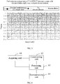
FIG. 5 is a schematic diagram of performance comparison between a case with deconvolution and a case without deconvolution according to an embodiment of the present invention; and -
FIG. 6 is a schematic structural diagram of an apparatus for reconstructing data according to an embodiment of the present invention. - To help a person skilled in the art better understand the technical solutions in the embodiments of the present invention, the following further describes the embodiments of the present invention in detail with reference to the accompanying drawings and implementation manners.
- Refer to
FIG. 1 , which is a flowchart of a method for reconstructing data according to an embodiment of the present invention. The method includes: - Step 101: Acquire an auto-correlation function of a root raised cosine filter coefficient and a fading factor of each antenna of channel estimation.
- In this embodiment, a root raised cosine filter at a receive end is preset, that is, once the root raised cosine filter at the receive end is determined, an auto-correlation function of the root raised cosine filter at the receive end is determined, and therefore Rp is determined.
- For acquiring the fading factor of each antenna of channel estimation, in this embodiment, a pilot is used by the receive end to perform channel estimation and obtain an estimated fading factor of each antenna, and the channel fading factors obtained by the channel estimation reflect channel information (including an amplitude and a phase). For a person skilled in the art, this process is already a well-known technology, and therefore no further details are provided herein.
- Step 102: Construct an L-dimension matrix of the auto-correlation function according to an antenna, where L is the number of valid paths found by the single antenna.
- Step 103: Process the L-dimension matrix of the auto-correlation function and a result of superposing the fading factor of each antenna to obtain an estimate value of an actual fading factor of the each antenna.
- In this embodiment, a solving operation may be performed on the matrix of the auto-correlation function and the result of superposing the fading factor of each antenna to obtain the estimate value of the actual fading factor of each antenna. The solving operation may specifically be performed according to a method of solving a set of linear equations but is not limited to this, and another algorithm may also be used for the obtaining, which is not limited in this embodiment.
- Step 104: Reconstruct received data according to the estimate value of the actual fading factor to obtain reconstructed data used for cancellation, which is close to actual sent data.
- The reconstructed data is used for interference cancellation, and the reconstructing data is adding fading to the received data.
- Further, before
step 101, the method may further include: reordering locations of the paths and locations of the fading factors according to an antenna number, so that the paths and the fading factors are separately arranged according to different antennas. - Further, based on all the foregoing embodiments, the processing the L-dimension matrix of the auto-correlation function and a result of superposing the fading factor of each antenna to obtain an estimate value of an actual fading factor of each antenna includes: performing inversion on the L-dimension matrix of the auto-correlation function to obtain an L-dimension inverse matrix of the auto-correlation function; performing deconvolution processing on the result of superposing the fading factor of each antenna and the L-dimension inverse matrix of the auto-correlation function to obtain the estimate value of the actual fading factor of each antenna; and then reconstructing the received data according to the estimate values of the actual fading factors to obtain actual sent data. The performing inversion on the L-dimension matrix of the auto-correlation function specifically includes: performing inversion on the L-dimension matrix of the auto-correlation function according to a successive over relaxation method (SOR, Successive Over Relaxation Method) or a decomposition method. This, however, is not a limitation, and another method may also be used, which is not limited in this embodiment.
- In the embodiment of the present invention, a pilot is used at the receive end to perform channel estimation, and the channel fading factors obtained by the channel estimation reflect channel information (an amplitude and a phase). For ease of understanding, a signal received by an antenna may be expressed as Y = HX + N, and deriving a fading factor H is using the pilot, that is, a known X (a transmitted pilot value is a known quantity) and Y (a received pilot value), to derive H. H can be used for all channels with simultaneous transmission, including a data channel. Solving a data signal is an inverse process, that is, deriving X from a known H and Y. During the reconstruction, an estimate value Y' of Y is derived according to an estimate value X' of the transmitted data and H.
- That is to say, in the embodiment of the present invention, at the receive end, in order to remove influence of the root raised cosine filter, actual fading factors are used for adding the fading during the data reconstruction. The actual fading factors are obtained through deconvolution of the fading factors obtained by channel estimation and the auto-correlation function Rp . In order to obtain the actual fading factors, deconvolution processing needs to be performed, specifically including the following:
- It is assumed that a relationship between an actual fading factor hj of each valid path and the fading factor h'j obtained by estimation is as follows:

S s in the formula (1);

- Then the reverse matrix


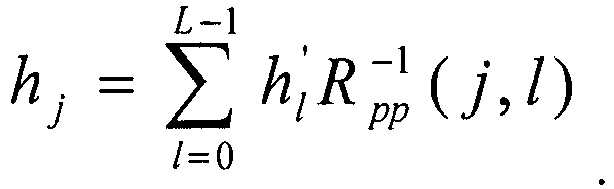
- Certainly, the determining the actual fading factor hj may be implemented by using another method, such as a linear solving method, that is, solving a set of linear equations

- Therefore, in the embodiment of the present invention, when interference cancellation is performed for reconstructed data, an estimate value of an actual fading factor is used to reconstruct received data, so that a process of performing the interference cancellation for the reconstructed data is closer to an actual sending process and closer to an originally sent signal, thereby improving cancellation efficiency and reducing interference. In addition, a signal-to-interference-plus-noise ratio of a user is improved during demodulation and performance is improved; and cell capacity is improved and more users are accessed on a precondition of ensuing that user performance does not change.
- In the embodiment of the present invention, after data is received by a receiver, one channel of the data experiences parameter estimation, such as estimation of a path or a fading factor, and an obtained estimation result is used as input of the reconstruction; another channel of data experiences demodulation to obtain information of a transmit end (that is, reconstructed soft information), and the reconstructed soft information is also used as input of the reconstruction; then, reconstruction processing is performed according to the two channels of input to obtain reconstruction of the actual fading factor; and finally, fading is added to the received data by using the actual fading factor to obtain reconstructed data used for cancellation.
- Refer to
FIG. 2 , which is a flowchart of a first application example of a method for reconstructing data according to an embodiment of the present invention. In this embodiment, a process of deconvolution processing is used as an example to obtain an estimate value of an actual fading factor of each antenna. The process specifically includes the following steps: - Step 201: Perform reordering and adjustment, that is, reorder locations of paths and locations of fading factors according to an indication of an antenna number, so that the paths and the fading factors are separately arranged according to different antennas, as shown in
FIG. 3 , which is a pareto diagram of locations of fading factors and locations of paths of an ith antenna after the locations of the fading factors and the locations of the paths are adjusted according to antenna numbers provided in an embodiment of the present invention. - Step 202: Acquire an auto-correlation function Rp of a root raised cosine filter, and acquire a fading factor h'j of each antenna of channel estimation.
Rp may be acquired through a storage table. - Step 203: Construct an L-dimension matrix Rpp respectively according to the antenna, where L is the number of valid paths found by the single antenna. (Using
FIG. 3 as an example, there are five valid paths for an antenna i, that is, Ni = L = 5.) - It is known that a location of a valid path found by the antenna i is tmpFD[Index[i]], and Ni represents the number of valid paths of the antenna i. Rpp is constructed. For an antenna, the matrix is a matrix of at most N*N, where N is the maximum number of paths.
- Step 204: Solve an inverse matrix

- Step 205: Perform deconvolution processing on the inverse matrix

- In this step, a formula

- A process from
step 202 to step 205 is performing deconvolution processing on each antenna to obtain the estimate value of the actual fading factor of each antenna. - Similarly, other antennas are similarly processed according to an implementation process from
step 202 to step 205, so as to obtain estimated actual fading factors of other antennas. - Step 206: Add fading to received data according to the estimate values of the actual fading factors to obtain reconstructed data used for cancellation.
- To help a person skilled in the art understand a process of calculating the estimate value of the actual fading factor of each antenna, the following uses a simple example for description. It should be noted that an implementation process in a practical application is much more complicated than the following implementation process, and the example is used for brief description only.
- The following uses processing of an antenna as an example, where the antenna has two valid paths. It is assumed that Rp(-4) = 0, Rp(-3) =-1, Rp(-2) = 0, Rp(-1) = 1, Rp(0) = 5, Rp(1) = 1, Rp(2) = 0, Rp(3)=-1, and Rp(4) 0; L = 2, τ0 = 0, and τ1 = 3; and h'0 = 8 and h'1 = 16 are obtained accordingly by estimation.


- A formula


- Refer to
FIG. 4 , which is a flowchart of a second application example of a method for reconstructing data according to an embodiment of the present invention. In this embodiment, a processing procedure of a solving operation is used as an example to obtain an estimate value of an actual fading factor of each antenna. In this embodiment, h'j and Rp are known, and a value of hj is estimated. A formula
- Step 401: Perform reordering and adjustment, that is, reorder locations of paths and locations of fading factors according to an indication of an antenna number, so that the paths and the fading factors are separately arranged according to different antennas.
FIG. 3 shows an ith antenna. - Step 402: Acquire an auto-correlation function Rp of a root raised cosine filter and acquire a fading factor h'j of each antenna of channel estimation.
- The auto-correlation function Rp may be acquired by using a storage table, that is to say, once the root raised cosine filter is determined, the auto-correlation function Rp of the root raised cosine filter is acquired from the corresponding storage table.
- Step 403: Construct an L-dimension matrix of the auto-correlation function, where L is the number of valid paths found by a single antenna.
- Step 404: Perform linear solving on the L-dimension matrix of the auto-correlation function and a result of superposing the fading factor h'j of each antenna to obtain the estimate value of the actual fading factor of each antenna.
- In this step, hj can be obtained by solving a set of linear equations

- Similarly, other antennas are similarly processed according to an implementation process from
step 402 to step 404, so as to obtain estimated actual fading factors of other antennas. - Step 405: Add fading to received data according to the estimate value of the actual fading factor to obtain reconstructed data used for cancellation.
- To help a person skilled in the art understand a process of calculating the estimate value of the actual fading factor of each antenna, the following uses a simple example for description. It should be noted that an implementation process in a practical application is much more complicated than the following implementation process, and the example is used for brief description only.
- It is assumed that Rp(-4) = 0, Rp(-3) = -1, Rp(-2) = 0, Rp(-1) = 1, Rp(0) = 5, Rp(1) = 1, Rp(2) = 0, Rp(3) =-1, and Rp(4) = 0; L = 2, τ0 = 0, and τ1 = 3; and h'0 =-8 and h'1 = 16 are obtained accordingly by estimation.
- The set of linear equations are as follows:

- That is:

- The following is obtained by solving the set of equations:

- As can be seen from the foregoing embodiments, in the embodiment of the present invention, using a fading factor after deconvolution or a fading factor obtained by solving may better restore fading on a channel, so that a process of performing interference cancellation for reconstructed data is closer to an actual sending process and closer to an originally sent signal, thereby improving cancellation efficiency, further reducing interference, improving a signal-to-interference-plus-noise ratio of a user during demodulation, and improving performance. In addition, cell capacity is improved and more users are accessed on a precondition of ensuring that user performance does not change.
- When there is only one user, in interference cancellation, a fading factor processed by deconvolution is used to reconstruct data, and then the data is demodulated, and performance obtained thereafter is consistent with performance without interference cancellation; and it is ensured that a gain of the interference cancellation is not affected by estimation accuracy.
FIG. 5 shows a schematic diagram of performance comparison between a case with deconvolution and a case without deconvolution. - As shown in
FIG. 5 , performance of interference cancellation by using a channel fading factor without deconvolution is even worse than original performance of a single user; whereas performance of interference cancellation by using a channel fading factor with deconvolution is almost the same as the original performance of a single user. - Based on the process of the foregoing embodiments, an embodiment of the present invention further provides an apparatus for reconstructing data. Refer to
FIG. 6 for details of a schematic diagram of the apparatus. The apparatus includes: an acquiringunit 61, a constructingunit 62, aprocessing unit 63, and a reconstructingunit 64. - The acquiring
unit 61 is configured to acquire an auto-correlation function of a root raised cosine filter coefficient and a fading factor of each antenna of channel estimation. - In this embodiment, a root raised cosine filter at a receive end is preset, that is, once the root raised cosine filter at the receive end is determined, an auto-correlation function of the root raised cosine filter at the receive end is determined, and therefore Rp is determined. For acquiring the fading factor of each antenna of channel estimation, in this embodiment, a pilot is used by the receive end to perform channel estimation and obtain an estimated fading factor of each antenna, and the channel fading factors obtained by the channel estimation reflect channel information (including an amplitude and a phase). For a person skilled in the art, this process is already a well-known technology, and therefore no further details are provided herein.
- The constructing
unit 62 is configured to construct an L-dimension matrix of the auto-correlation function according to an antenna, where L is the number of valid paths found by a single antenna. UsingFIG. 3 as an example, there are five valid paths for an antenna i, that is, Ni = L = 5. It is known that a location of a valid path found by the antenna i is tmpFD[Index[i]], and Ni represents the number of valid paths of the antenna i. Rpp is constructed. For an antenna, the matrix is a matrix of at most N*N, where N is the maximum number of paths. - The
processing unit 63 is configured to process the L-dimension matrix of the auto-correlation function constructed by the constructingunit 62 and a result of superposing the fading factor of each antenna acquired by the acquiringunit 61 to obtain an estimate value of an actual fading factor of each antenna. - The reconstructing
unit 64 is configured to reconstruct (that is, add fading to) received data according to the estimate values of the actual fading factors obtained by the processing unit to obtain reconstructed data used for cancellation. - The reconstructed data is used for interference cancellation, and the reconstructing data is adding fading to the received data.
- In this embodiment, the processing unit includes: a solving processing unit, configured to perform a solving operation on the L-dimension matrix of the auto-correlation function constructed by the constructing unit and the result of superposing the fading factor of each antenna acquired by the acquiring unit to obtain the estimate value of the actual fading factor of each antenna. The solving operation may be performed according to a method of solving a set of linear equations to obtain the estimate value of the actual fading factor of each antenna.
- Preferably, the processing unit may include: an inverting unit and a deconvolution processing unit. The inverting unit is connected to the constructing unit, and is configured to perform inversion on the L-dimension matrix of the auto-correlation function constructed by the constructing unit to obtain an L-dimension inverse matrix of the auto-correlation function; and may specifically perform inversion on the L-dimension matrix of the auto-correlation function according to a successive over relaxation method SOR or a decomposition method, which is not limited herein. The deconvolution processing unit is configured to perform deconvolution processing on the result of superposing the fading factor of each antenna acquired by the acquiring unit and the L-dimension inverse matrix of the auto-correlation function obtained by the inverting unit to obtain the estimate value of the actual fading factor of each antenna. In this step, a formula

FIG. 3 , and no further details are provided herein. - Preferably, the apparatus may be a receiver, or may be integrated into a receiver, or may be independently deployed, and this is not limited in this embodiment.
- For an implementation process of functions and roles of each unit of the apparatus, refer to the corresponding implementation process in the foregoing methods, and no further details are provided herein.
- It should be further noted that in this specification, the terms "include", "comprise", or any variation thereof are intended to cover a non-exclusive inclusion, therefore, enabling a process, a method, an article, or a device, which includes a series of elements, to include not only such elements, but also other elements that are not specifically listed, or inherent elements of the process, the method, the article, or the device. If no more limitations are made, an element limited by the term "include a/an..." does not exclude that there are other same elements existing in the process, the method, the article, or the device, which includes the element.
- According to the description of the foregoing embodiments, a person skilled in the art may clearly understand that the present invention may be implemented by software in addition to a necessary universal hardware platform, or by hardware, of course. However, in most circumstances, the former is a better implementation manner. Based on such an understanding, the technical solutions in the present invention, essentially, or the part contributing to the prior art, may be implemented in a form of a software product. The computer software product may be stored in a storage medium, such as a ROM/RAM, a magnetic disk, or an optical disc, and includes several instructions for instructing a computer device (which may be a personal computer, a server, or a network device) to perform the methods described in each embodiment or some part of the embodiments of the present invention. The foregoing descriptions are merely exemplary embodiments of the present invention. It should be pointed out that a person of ordinary skill in the art may make several improvements and modifications within the scope of the claims.
Claims (9)
- A method for reconstructing data, comprising:acquiring(101) an auto-correlation function Rp of a root raised cosine filter coefficient and performing channel estimation and obtaining a fading factor of each antenna by using a pilot;constructing(102) an L-dimension matrix Rpp of the auto-correlation function according to the antenna, where L is the number of valid paths found by the single antenna; wherein the Rpp is a coefficient matrix formed by all Rp
S , and the Rpp is as follows: obtaining the actual fading factor hj by substituting h'l and


andreconstructing(104) received data according to the estimate value of the actual fading factor hj to obtain reconstructed data used for cancellation. - The method according to claim 1, wherein the

- The method according to any one of claims 1 and 2, wherein the reconstructing received data according to the estimate values of the actual fading factors to obtain actual sent data specifically comprises:adding fading to the received data according to the estimate values of the actual fading factors to obtain the actual sent data.
- The method according to any one of claims 1 to 3, wherein the method further comprises:reordering locations of paths and locations of fading factors according to an antenna number, so that the paths and the fading factors are separately arranged according to different antennas.
- An apparatus for reconstructing data, comprising:an acquiring unit(61), configured to acquire an auto-correlation function Rp of a root raised cosine filter coefficient and performing channel estimation and obtaining a fading factor of each antenna by using a pilot;a constructing unit(62), configured to construct an L-dimension matrix Rpp of the auto-correlation function according to the antenna, wherein L is the number of valid paths found by the single antenna; wherein the Rpp is a coefficient matrix formed by all R p
S , and the Rpp is as follows: the processing unit(63), configured to obtain an estimate value of actual fading factor hj by substituting h'l and


anda reconstructing unit(64), configured to reconstruct received data according to the estimate value of the actual fading factor hj obtained by the processing unit to obtain reconstructed data used for cancellation. - The apparatus according to claim 5, wherein the

- The apparatus according to any one of claims 5 to 6, wherein the reconstructing unit is specifically configured to add fading to the received data according to the estimate values of the actual fading factors obtained by the processing unit to obtain reconstructed data used for cancellation.
- The apparatus according to any one of claims 5 to 6, wherein the apparatus further comprises:a location ordering unit, connected to the acquiring unit and configured to reorder locations of paths and locations of fading factors according to an antenna number, so that the paths and the fading factors are separately arranged according to different antennas.
- The apparatus according to any one of claims 5 to 6, wherein the apparatus is a receiver or integrated into a receiver.
Applications Claiming Priority (2)
| Application Number | Priority Date | Filing Date | Title |
|---|---|---|---|
| CN201110209714.XA CN102271025B (en) | 2011-07-25 | 2011-07-25 | A method and device for reconstructing data |
| PCT/CN2012/079136 WO2013013616A1 (en) | 2011-07-25 | 2012-07-25 | Data reconstruction method and device |
Publications (3)
| Publication Number | Publication Date |
|---|---|
| EP2728779A1 EP2728779A1 (en) | 2014-05-07 |
| EP2728779A4 EP2728779A4 (en) | 2014-07-09 |
| EP2728779B1 true EP2728779B1 (en) | 2017-09-06 |
Family
ID=45053198
Family Applications (1)
| Application Number | Title | Priority Date | Filing Date |
|---|---|---|---|
| EP12816839.0A Not-in-force EP2728779B1 (en) | 2011-07-25 | 2012-07-25 | Data reconstruction method and device |
Country Status (4)
| Country | Link |
|---|---|
| US (1) | US9350569B2 (en) |
| EP (1) | EP2728779B1 (en) |
| CN (1) | CN102271025B (en) |
| WO (1) | WO2013013616A1 (en) |
Families Citing this family (3)
| Publication number | Priority date | Publication date | Assignee | Title |
|---|---|---|---|---|
| CN102271025B (en) | 2011-07-25 | 2014-02-26 | 上海华为技术有限公司 | A method and device for reconstructing data |
| EP2991296B1 (en) * | 2013-06-27 | 2017-05-03 | Huawei Technologies Co., Ltd. | Channel estimation method and receiver |
| CN104170339B (en) * | 2014-01-29 | 2016-11-16 | 华为技术有限公司 | Interference suppression method and device |
Family Cites Families (11)
| Publication number | Priority date | Publication date | Assignee | Title |
|---|---|---|---|---|
| US7068628B2 (en) * | 2000-05-22 | 2006-06-27 | At&T Corp. | MIMO OFDM system |
| CN1163014C (en) * | 2002-05-23 | 2004-08-18 | 北京大学 | Code division multiple access spreading and despreading method and its transmitter, receiver and communication system |
| EP1447927A1 (en) * | 2003-02-17 | 2004-08-18 | France Telecom | Signal processing apparatus and method |
| US7042967B2 (en) * | 2003-03-03 | 2006-05-09 | Interdigital Technology Corporation | Reduced complexity sliding window based equalizer |
| US7821913B2 (en) * | 2005-03-29 | 2010-10-26 | Qualcomm Incorporated | Method and apparatus for data and pilot structures supporting equalization |
| CN100578954C (en) * | 2006-05-10 | 2010-01-06 | 华为技术有限公司 | Method for receiving multipath signal, device for calculating weighted value of each path and RAKE receiver |
| CN101277127B (en) * | 2008-03-21 | 2011-10-26 | 华为技术有限公司 | Method for receiving signal as well as receiver, method for combining signal as well as module |
| JP2010062944A (en) * | 2008-09-04 | 2010-03-18 | Kyushu Institute Of Technology | Wireless communications system, wireless reception device, and wireless transmission device |
| CN101895311B (en) * | 2010-06-18 | 2013-08-07 | 华为技术有限公司 | Signal-receiving method and receiver |
| CN102098083B (en) * | 2010-12-27 | 2015-01-07 | 华为技术有限公司 | Reconstruction method and device of enhanced dedicated channel |
| CN102271025B (en) * | 2011-07-25 | 2014-02-26 | 上海华为技术有限公司 | A method and device for reconstructing data |
-
2011
- 2011-07-25 CN CN201110209714.XA patent/CN102271025B/en not_active Expired - Fee Related
-
2012
- 2012-07-25 WO PCT/CN2012/079136 patent/WO2013013616A1/en not_active Ceased
- 2012-07-25 EP EP12816839.0A patent/EP2728779B1/en not_active Not-in-force
-
2014
- 2014-01-27 US US14/164,675 patent/US9350569B2/en active Active
Non-Patent Citations (1)
| Title |
|---|
| None * |
Also Published As
| Publication number | Publication date |
|---|---|
| CN102271025A (en) | 2011-12-07 |
| EP2728779A4 (en) | 2014-07-09 |
| EP2728779A1 (en) | 2014-05-07 |
| US20140140383A1 (en) | 2014-05-22 |
| CN102271025B (en) | 2014-02-26 |
| US9350569B2 (en) | 2016-05-24 |
| WO2013013616A1 (en) | 2013-01-31 |
Similar Documents
| Publication | Publication Date | Title |
|---|---|---|
| EP2589192B1 (en) | Mimo channel state information estimation with coupled iterative two-stage ranking | |
| CN103503359B (en) | Method and apparatus for determining UE mobility conditions | |
| CN102647387B (en) | The removing method of co-channel interference and device | |
| US20130215945A1 (en) | Signal processing unit employing a blind channel estimation algorithm and method of operating a receiver apparatus | |
| EP2897303B1 (en) | Code word feedback method and receiver | |
| CN101841375A (en) | Testing method and device for multi-input multi-output single carrier block transmission system | |
| US9954695B2 (en) | Channel measurement method for large-scale antennas, and user terminal | |
| US7548589B2 (en) | Method and apparatus for generating weights for transmit diversity in wireless communication | |
| US9031123B2 (en) | Communication system and method using subspace interference cancellation | |
| US9237038B2 (en) | Channel and noise estimation method and associated apparatus | |
| WO2011017032A1 (en) | Signal and noise power estimation by projecting a received signal on channel response autocorrelation matrix eigenvector basis | |
| CN109617579B (en) | Enhanced Noeman large-scale MIMO precoding method | |
| EP2491670B1 (en) | System and method for multiple input, multiple output (mimo) communications | |
| CN1833419B (en) | Method for pre-filtering training sequences in a radiocommunication system | |
| EP2728779A1 (en) | Data reconstruction method and device | |
| CN102055691A (en) | Estimation processing method for beamforming (BF) weight and base station | |
| EP2075969B1 (en) | Method and apparatus for performing channel equalization on a mimo signal | |
| CN104753834A (en) | Channel estimation method and channel estimation device | |
| CN112217751B (en) | 5G anti-interference channel estimation method and system | |
| WO2006039793A1 (en) | Pilot symbol assisted modulation signal processing systems and methods | |
| EP2317665B1 (en) | Technique for transmitted streams combining weight determination in a receiver of a SIMO or MIMO system | |
| US20120300830A1 (en) | Equaliser for wireless receivers with normalised coefficients | |
| CN102437899B (en) | Method and device for determining uplink CQI (Channel Quality Indicator) value | |
| CN103379051A (en) | Multi-path channel noise variance estimation method | |
| Brandt | Polynomial matrix decompositions: Evaluation of algorithms with an application to wideband MIMO communications |
Legal Events
| Date | Code | Title | Description |
|---|---|---|---|
| PUAI | Public reference made under article 153(3) epc to a published international application that has entered the european phase |
Free format text: ORIGINAL CODE: 0009012 |
|
| 17P | Request for examination filed |
Effective date: 20140129 |
|
| AK | Designated contracting states |
Kind code of ref document: A1 Designated state(s): AL AT BE BG CH CY CZ DE DK EE ES FI FR GB GR HR HU IE IS IT LI LT LU LV MC MK MT NL NO PL PT RO RS SE SI SK SM TR |
|
| A4 | Supplementary search report drawn up and despatched |
Effective date: 20140605 |
|
| RIC1 | Information provided on ipc code assigned before grant |
Ipc: H04L 1/06 20060101ALI20140530BHEP Ipc: H04L 25/02 20060101ALI20140530BHEP Ipc: H04L 1/00 20060101AFI20140530BHEP |
|
| DAX | Request for extension of the european patent (deleted) | ||
| GRAP | Despatch of communication of intention to grant a patent |
Free format text: ORIGINAL CODE: EPIDOSNIGR1 |
|
| INTG | Intention to grant announced |
Effective date: 20161205 |
|
| RAP1 | Party data changed (applicant data changed or rights of an application transferred) |
Owner name: HUAWEI TECHNOLOGIES CO., LTD. |
|
| GRAS | Grant fee paid |
Free format text: ORIGINAL CODE: EPIDOSNIGR3 |
|
| GRAJ | Information related to disapproval of communication of intention to grant by the applicant or resumption of examination proceedings by the epo deleted |
Free format text: ORIGINAL CODE: EPIDOSDIGR1 |
|
| GRAL | Information related to payment of fee for publishing/printing deleted |
Free format text: ORIGINAL CODE: EPIDOSDIGR3 |
|
| GRAP | Despatch of communication of intention to grant a patent |
Free format text: ORIGINAL CODE: EPIDOSNIGR1 |
|
| INTC | Intention to grant announced (deleted) | ||
| INTG | Intention to grant announced |
Effective date: 20170511 |
|
| GRAJ | Information related to disapproval of communication of intention to grant by the applicant or resumption of examination proceedings by the epo deleted |
Free format text: ORIGINAL CODE: EPIDOSDIGR1 |
|
| GRAL | Information related to payment of fee for publishing/printing deleted |
Free format text: ORIGINAL CODE: EPIDOSDIGR3 |
|
| GRAP | Despatch of communication of intention to grant a patent |
Free format text: ORIGINAL CODE: EPIDOSNIGR1 |
|
| INTC | Intention to grant announced (deleted) | ||
| INTG | Intention to grant announced |
Effective date: 20170707 |
|
| GRAA | (expected) grant |
Free format text: ORIGINAL CODE: 0009210 |
|
| AK | Designated contracting states |
Kind code of ref document: B1 Designated state(s): AL AT BE BG CH CY CZ DE DK EE ES FI FR GB GR HR HU IE IS IT LI LT LU LV MC MK MT NL NO PL PT RO RS SE SI SK SM TR |
|
| REG | Reference to a national code |
Ref country code: GB Ref legal event code: FG4D |
|
| REG | Reference to a national code |
Ref country code: CH Ref legal event code: EP Ref country code: AT Ref legal event code: REF Ref document number: 926954 Country of ref document: AT Kind code of ref document: T Effective date: 20170915 |
|
| REG | Reference to a national code |
Ref country code: IE Ref legal event code: FG4D |
|
| REG | Reference to a national code |
Ref country code: DE Ref legal event code: R096 Ref document number: 602012037080 Country of ref document: DE |
|
| REG | Reference to a national code |
Ref country code: NL Ref legal event code: MP Effective date: 20170906 |
|
| REG | Reference to a national code |
Ref country code: LT Ref legal event code: MG4D |
|
| PG25 | Lapsed in a contracting state [announced via postgrant information from national office to epo] |
Ref country code: LT Free format text: LAPSE BECAUSE OF FAILURE TO SUBMIT A TRANSLATION OF THE DESCRIPTION OR TO PAY THE FEE WITHIN THE PRESCRIBED TIME-LIMIT Effective date: 20170906 Ref country code: SE Free format text: LAPSE BECAUSE OF FAILURE TO SUBMIT A TRANSLATION OF THE DESCRIPTION OR TO PAY THE FEE WITHIN THE PRESCRIBED TIME-LIMIT Effective date: 20170906 Ref country code: FI Free format text: LAPSE BECAUSE OF FAILURE TO SUBMIT A TRANSLATION OF THE DESCRIPTION OR TO PAY THE FEE WITHIN THE PRESCRIBED TIME-LIMIT Effective date: 20170906 Ref country code: HR Free format text: LAPSE BECAUSE OF FAILURE TO SUBMIT A TRANSLATION OF THE DESCRIPTION OR TO PAY THE FEE WITHIN THE PRESCRIBED TIME-LIMIT Effective date: 20170906 Ref country code: NO Free format text: LAPSE BECAUSE OF FAILURE TO SUBMIT A TRANSLATION OF THE DESCRIPTION OR TO PAY THE FEE WITHIN THE PRESCRIBED TIME-LIMIT Effective date: 20171206 |
|
| REG | Reference to a national code |
Ref country code: AT Ref legal event code: MK05 Ref document number: 926954 Country of ref document: AT Kind code of ref document: T Effective date: 20170906 |
|
| PG25 | Lapsed in a contracting state [announced via postgrant information from national office to epo] |
Ref country code: ES Free format text: LAPSE BECAUSE OF FAILURE TO SUBMIT A TRANSLATION OF THE DESCRIPTION OR TO PAY THE FEE WITHIN THE PRESCRIBED TIME-LIMIT Effective date: 20170906 Ref country code: RS Free format text: LAPSE BECAUSE OF FAILURE TO SUBMIT A TRANSLATION OF THE DESCRIPTION OR TO PAY THE FEE WITHIN THE PRESCRIBED TIME-LIMIT Effective date: 20170906 Ref country code: LV Free format text: LAPSE BECAUSE OF FAILURE TO SUBMIT A TRANSLATION OF THE DESCRIPTION OR TO PAY THE FEE WITHIN THE PRESCRIBED TIME-LIMIT Effective date: 20170906 Ref country code: BG Free format text: LAPSE BECAUSE OF FAILURE TO SUBMIT A TRANSLATION OF THE DESCRIPTION OR TO PAY THE FEE WITHIN THE PRESCRIBED TIME-LIMIT Effective date: 20171206 Ref country code: GR Free format text: LAPSE BECAUSE OF FAILURE TO SUBMIT A TRANSLATION OF THE DESCRIPTION OR TO PAY THE FEE WITHIN THE PRESCRIBED TIME-LIMIT Effective date: 20171207 |
|
| PG25 | Lapsed in a contracting state [announced via postgrant information from national office to epo] |
Ref country code: NL Free format text: LAPSE BECAUSE OF FAILURE TO SUBMIT A TRANSLATION OF THE DESCRIPTION OR TO PAY THE FEE WITHIN THE PRESCRIBED TIME-LIMIT Effective date: 20170906 |
|
| PG25 | Lapsed in a contracting state [announced via postgrant information from national office to epo] |
Ref country code: PL Free format text: LAPSE BECAUSE OF FAILURE TO SUBMIT A TRANSLATION OF THE DESCRIPTION OR TO PAY THE FEE WITHIN THE PRESCRIBED TIME-LIMIT Effective date: 20170906 Ref country code: CZ Free format text: LAPSE BECAUSE OF FAILURE TO SUBMIT A TRANSLATION OF THE DESCRIPTION OR TO PAY THE FEE WITHIN THE PRESCRIBED TIME-LIMIT Effective date: 20170906 Ref country code: RO Free format text: LAPSE BECAUSE OF FAILURE TO SUBMIT A TRANSLATION OF THE DESCRIPTION OR TO PAY THE FEE WITHIN THE PRESCRIBED TIME-LIMIT Effective date: 20170906 |
|
| PG25 | Lapsed in a contracting state [announced via postgrant information from national office to epo] |
Ref country code: IS Free format text: LAPSE BECAUSE OF FAILURE TO SUBMIT A TRANSLATION OF THE DESCRIPTION OR TO PAY THE FEE WITHIN THE PRESCRIBED TIME-LIMIT Effective date: 20180106 Ref country code: SM Free format text: LAPSE BECAUSE OF FAILURE TO SUBMIT A TRANSLATION OF THE DESCRIPTION OR TO PAY THE FEE WITHIN THE PRESCRIBED TIME-LIMIT Effective date: 20170906 Ref country code: EE Free format text: LAPSE BECAUSE OF FAILURE TO SUBMIT A TRANSLATION OF THE DESCRIPTION OR TO PAY THE FEE WITHIN THE PRESCRIBED TIME-LIMIT Effective date: 20170906 Ref country code: IT Free format text: LAPSE BECAUSE OF FAILURE TO SUBMIT A TRANSLATION OF THE DESCRIPTION OR TO PAY THE FEE WITHIN THE PRESCRIBED TIME-LIMIT Effective date: 20170906 Ref country code: AT Free format text: LAPSE BECAUSE OF FAILURE TO SUBMIT A TRANSLATION OF THE DESCRIPTION OR TO PAY THE FEE WITHIN THE PRESCRIBED TIME-LIMIT Effective date: 20170906 Ref country code: SK Free format text: LAPSE BECAUSE OF FAILURE TO SUBMIT A TRANSLATION OF THE DESCRIPTION OR TO PAY THE FEE WITHIN THE PRESCRIBED TIME-LIMIT Effective date: 20170906 |
|
| REG | Reference to a national code |
Ref country code: DE Ref legal event code: R097 Ref document number: 602012037080 Country of ref document: DE |
|
| PLBE | No opposition filed within time limit |
Free format text: ORIGINAL CODE: 0009261 |
|
| STAA | Information on the status of an ep patent application or granted ep patent |
Free format text: STATUS: NO OPPOSITION FILED WITHIN TIME LIMIT |
|
| PG25 | Lapsed in a contracting state [announced via postgrant information from national office to epo] |
Ref country code: DK Free format text: LAPSE BECAUSE OF FAILURE TO SUBMIT A TRANSLATION OF THE DESCRIPTION OR TO PAY THE FEE WITHIN THE PRESCRIBED TIME-LIMIT Effective date: 20170906 |
|
| 26N | No opposition filed |
Effective date: 20180607 |
|
| PG25 | Lapsed in a contracting state [announced via postgrant information from national office to epo] |
Ref country code: SI Free format text: LAPSE BECAUSE OF FAILURE TO SUBMIT A TRANSLATION OF THE DESCRIPTION OR TO PAY THE FEE WITHIN THE PRESCRIBED TIME-LIMIT Effective date: 20170906 |
|
| REG | Reference to a national code |
Ref country code: CH Ref legal event code: PL |
|
| PG25 | Lapsed in a contracting state [announced via postgrant information from national office to epo] |
Ref country code: LU Free format text: LAPSE BECAUSE OF NON-PAYMENT OF DUE FEES Effective date: 20180725 Ref country code: MC Free format text: LAPSE BECAUSE OF FAILURE TO SUBMIT A TRANSLATION OF THE DESCRIPTION OR TO PAY THE FEE WITHIN THE PRESCRIBED TIME-LIMIT Effective date: 20170906 |
|
| REG | Reference to a national code |
Ref country code: BE Ref legal event code: MM Effective date: 20180731 |
|
| REG | Reference to a national code |
Ref country code: IE Ref legal event code: MM4A |
|
| PG25 | Lapsed in a contracting state [announced via postgrant information from national office to epo] |
Ref country code: IE Free format text: LAPSE BECAUSE OF NON-PAYMENT OF DUE FEES Effective date: 20180725 Ref country code: LI Free format text: LAPSE BECAUSE OF NON-PAYMENT OF DUE FEES Effective date: 20180731 Ref country code: CH Free format text: LAPSE BECAUSE OF NON-PAYMENT OF DUE FEES Effective date: 20180731 Ref country code: FR Free format text: LAPSE BECAUSE OF NON-PAYMENT OF DUE FEES Effective date: 20180731 |
|
| PG25 | Lapsed in a contracting state [announced via postgrant information from national office to epo] |
Ref country code: BE Free format text: LAPSE BECAUSE OF NON-PAYMENT OF DUE FEES Effective date: 20180731 |
|
| PG25 | Lapsed in a contracting state [announced via postgrant information from national office to epo] |
Ref country code: MT Free format text: LAPSE BECAUSE OF NON-PAYMENT OF DUE FEES Effective date: 20180725 |
|
| PG25 | Lapsed in a contracting state [announced via postgrant information from national office to epo] |
Ref country code: TR Free format text: LAPSE BECAUSE OF FAILURE TO SUBMIT A TRANSLATION OF THE DESCRIPTION OR TO PAY THE FEE WITHIN THE PRESCRIBED TIME-LIMIT Effective date: 20170906 |
|
| PG25 | Lapsed in a contracting state [announced via postgrant information from national office to epo] |
Ref country code: PT Free format text: LAPSE BECAUSE OF FAILURE TO SUBMIT A TRANSLATION OF THE DESCRIPTION OR TO PAY THE FEE WITHIN THE PRESCRIBED TIME-LIMIT Effective date: 20170906 Ref country code: HU Free format text: LAPSE BECAUSE OF FAILURE TO SUBMIT A TRANSLATION OF THE DESCRIPTION OR TO PAY THE FEE WITHIN THE PRESCRIBED TIME-LIMIT; INVALID AB INITIO Effective date: 20120725 |
|
| PG25 | Lapsed in a contracting state [announced via postgrant information from national office to epo] |
Ref country code: MK Free format text: LAPSE BECAUSE OF NON-PAYMENT OF DUE FEES Effective date: 20170906 Ref country code: CY Free format text: LAPSE BECAUSE OF FAILURE TO SUBMIT A TRANSLATION OF THE DESCRIPTION OR TO PAY THE FEE WITHIN THE PRESCRIBED TIME-LIMIT Effective date: 20170906 |
|
| PG25 | Lapsed in a contracting state [announced via postgrant information from national office to epo] |
Ref country code: AL Free format text: LAPSE BECAUSE OF FAILURE TO SUBMIT A TRANSLATION OF THE DESCRIPTION OR TO PAY THE FEE WITHIN THE PRESCRIBED TIME-LIMIT Effective date: 20170906 |
|
| PGFP | Annual fee paid to national office [announced via postgrant information from national office to epo] |
Ref country code: GB Payment date: 20230601 Year of fee payment: 12 |
|
| PGFP | Annual fee paid to national office [announced via postgrant information from national office to epo] |
Ref country code: DE Payment date: 20230531 Year of fee payment: 12 |
|
| REG | Reference to a national code |
Ref country code: DE Ref legal event code: R119 Ref document number: 602012037080 Country of ref document: DE |
|
| GBPC | Gb: european patent ceased through non-payment of renewal fee |
Effective date: 20240725 |
|
| PG25 | Lapsed in a contracting state [announced via postgrant information from national office to epo] |
Ref country code: DE Free format text: LAPSE BECAUSE OF NON-PAYMENT OF DUE FEES Effective date: 20250201 |
|
| PG25 | Lapsed in a contracting state [announced via postgrant information from national office to epo] |
Ref country code: GB Free format text: LAPSE BECAUSE OF NON-PAYMENT OF DUE FEES Effective date: 20240725 |