EP2728687A1 - Structure and method for connecting former of superconducting cable - Google Patents
Structure and method for connecting former of superconducting cable Download PDFInfo
- Publication number
- EP2728687A1 EP2728687A1 EP13797579.3A EP13797579A EP2728687A1 EP 2728687 A1 EP2728687 A1 EP 2728687A1 EP 13797579 A EP13797579 A EP 13797579A EP 2728687 A1 EP2728687 A1 EP 2728687A1
- Authority
- EP
- European Patent Office
- Prior art keywords
- formers
- connection
- wedge
- sections
- shaped gap
- Prior art date
- Legal status (The legal status is an assumption and is not a legal conclusion. Google has not performed a legal analysis and makes no representation as to the accuracy of the status listed.)
- Withdrawn
Links
Images


Classifications
-
- H—ELECTRICITY
- H01—ELECTRIC ELEMENTS
- H01R—ELECTRICALLY-CONDUCTIVE CONNECTIONS; STRUCTURAL ASSOCIATIONS OF A PLURALITY OF MUTUALLY-INSULATED ELECTRICAL CONNECTING ELEMENTS; COUPLING DEVICES; CURRENT COLLECTORS
- H01R4/00—Electrically-conductive connections between two or more conductive members in direct contact, i.e. touching one another; Means for effecting or maintaining such contact; Electrically-conductive connections having two or more spaced connecting locations for conductors and using contact members penetrating insulation
- H01R4/58—Electrically-conductive connections between two or more conductive members in direct contact, i.e. touching one another; Means for effecting or maintaining such contact; Electrically-conductive connections having two or more spaced connecting locations for conductors and using contact members penetrating insulation characterised by the form or material of the contacting members
- H01R4/68—Connections to or between superconductive connectors
-
- H—ELECTRICITY
- H01—ELECTRIC ELEMENTS
- H01B—CABLES; CONDUCTORS; INSULATORS; SELECTION OF MATERIALS FOR THEIR CONDUCTIVE, INSULATING OR DIELECTRIC PROPERTIES
- H01B12/00—Superconductive or hyperconductive conductors, cables, or transmission lines
- H01B12/16—Superconductive or hyperconductive conductors, cables, or transmission lines characterised by cooling
-
- H—ELECTRICITY
- H01—ELECTRIC ELEMENTS
- H01B—CABLES; CONDUCTORS; INSULATORS; SELECTION OF MATERIALS FOR THEIR CONDUCTIVE, INSULATING OR DIELECTRIC PROPERTIES
- H01B13/00—Apparatus or processes specially adapted for manufacturing conductors or cables
- H01B13/0036—Details
-
- H—ELECTRICITY
- H01—ELECTRIC ELEMENTS
- H01R—ELECTRICALLY-CONDUCTIVE CONNECTIONS; STRUCTURAL ASSOCIATIONS OF A PLURALITY OF MUTUALLY-INSULATED ELECTRICAL CONNECTING ELEMENTS; COUPLING DEVICES; CURRENT COLLECTORS
- H01R4/00—Electrically-conductive connections between two or more conductive members in direct contact, i.e. touching one another; Means for effecting or maintaining such contact; Electrically-conductive connections having two or more spaced connecting locations for conductors and using contact members penetrating insulation
- H01R4/02—Soldered or welded connections
- H01R4/029—Welded connections
-
- H—ELECTRICITY
- H02—GENERATION; CONVERSION OR DISTRIBUTION OF ELECTRIC POWER
- H02G—INSTALLATION OF ELECTRIC CABLES OR LINES, OR OF COMBINED OPTICAL AND ELECTRIC CABLES OR LINES
- H02G1/00—Methods or apparatus specially adapted for installing, maintaining, repairing or dismantling electric cables or lines
- H02G1/14—Methods or apparatus specially adapted for installing, maintaining, repairing or dismantling electric cables or lines for joining or terminating cables
-
- H—ELECTRICITY
- H02—GENERATION; CONVERSION OR DISTRIBUTION OF ELECTRIC POWER
- H02G—INSTALLATION OF ELECTRIC CABLES OR LINES, OR OF COMBINED OPTICAL AND ELECTRIC CABLES OR LINES
- H02G15/00—Cable fittings
- H02G15/34—Cable fittings for cryogenic cables
-
- H—ELECTRICITY
- H10—SEMICONDUCTOR DEVICES; ELECTRIC SOLID-STATE DEVICES NOT OTHERWISE PROVIDED FOR
- H10N—ELECTRIC SOLID-STATE DEVICES NOT OTHERWISE PROVIDED FOR
- H10N60/00—Superconducting devices
- H10N60/80—Constructional details
-
- Y—GENERAL TAGGING OF NEW TECHNOLOGICAL DEVELOPMENTS; GENERAL TAGGING OF CROSS-SECTIONAL TECHNOLOGIES SPANNING OVER SEVERAL SECTIONS OF THE IPC; TECHNICAL SUBJECTS COVERED BY FORMER USPC CROSS-REFERENCE ART COLLECTIONS [XRACs] AND DIGESTS
- Y02—TECHNOLOGIES OR APPLICATIONS FOR MITIGATION OR ADAPTATION AGAINST CLIMATE CHANGE
- Y02E—REDUCTION OF GREENHOUSE GAS [GHG] EMISSIONS, RELATED TO ENERGY GENERATION, TRANSMISSION OR DISTRIBUTION
- Y02E40/00—Technologies for an efficient electrical power generation, transmission or distribution
- Y02E40/60—Superconducting electric elements or equipment; Power systems integrating superconducting elements or equipment
-
- Y—GENERAL TAGGING OF NEW TECHNOLOGICAL DEVELOPMENTS; GENERAL TAGGING OF CROSS-SECTIONAL TECHNOLOGIES SPANNING OVER SEVERAL SECTIONS OF THE IPC; TECHNICAL SUBJECTS COVERED BY FORMER USPC CROSS-REFERENCE ART COLLECTIONS [XRACs] AND DIGESTS
- Y10—TECHNICAL SUBJECTS COVERED BY FORMER USPC
- Y10T—TECHNICAL SUBJECTS COVERED BY FORMER US CLASSIFICATION
- Y10T29/00—Metal working
- Y10T29/49—Method of mechanical manufacture
- Y10T29/49002—Electrical device making
- Y10T29/49117—Conductor or circuit manufacturing
- Y10T29/49194—Assembling elongated conductors, e.g., splicing, etc.
-
- Y—GENERAL TAGGING OF NEW TECHNOLOGICAL DEVELOPMENTS; GENERAL TAGGING OF CROSS-SECTIONAL TECHNOLOGIES SPANNING OVER SEVERAL SECTIONS OF THE IPC; TECHNICAL SUBJECTS COVERED BY FORMER USPC CROSS-REFERENCE ART COLLECTIONS [XRACs] AND DIGESTS
- Y10—TECHNICAL SUBJECTS COVERED BY FORMER USPC
- Y10T—TECHNICAL SUBJECTS COVERED BY FORMER US CLASSIFICATION
- Y10T29/00—Metal working
- Y10T29/49—Method of mechanical manufacture
- Y10T29/49826—Assembling or joining
Definitions
- the present invention relates to a structure and a method for connecting formers located at centers of cable cores of superconducting cables.
- a superconducting cable includes a cable core which has a former and a superconducting wire and a thermal insulation tube which has a vacuum double tube structure to contain the cable core, and liquid cooling medium of ultralow temperature is circulated to cool the cable core inside the thermal insulation tube.
- the former is formed to be hollow and the liquid cooling medium is circulated also inside the hollow section.
- the superconducting cable In a case where the superconducting cable is used as a power supply line, the superconducting cable needs to be laid out from the power supply source to the distant power-consuming area; however, the superconducting cable has a limitation in length of single cable for manufacturing or logistic reasons. Thus, when performing long-distance cable laying, many superconducting cables need to be connected at the laying site.
- An object of the present invention is to provide a structure and a method for connecting superconducting cables which maintains an internal hollow state of formers and enables good electrical transmission of superconductive conductor layers.
- the present invention is a connection structure of formers for connecting hollow formers provided inside superconducting cables, wherein one end section and the other end section of a hollow connection conduit are inserted into open sections leading to hollow internal sections formed at connection end sections of the respective formers, and the opposed connection end sections of the respective formers are connected to each other by welding.
- connection structure according to the present invention may have a configuration in which a connection end section of each of the formers is formed of an end surface including an inclined surface which is inclined with respect to a longer direction of each of the formers, and corresponding inclined surfaces at the connection end sections of the respective formers are opposed to each other so as to form a wedge-shaped gap, and opposed end surfaces are connected to each other with a welding filler material.
- connection structure according to the present invention may have a configuration in which each of the end surfaces includes two inclined surfaces, one being large and the other being small, among two wedge-shaped gaps, one being a large wedge-shaped gap and the other being a small wedge-shaped gap, which are formed by the inclined surfaces between the opposed connection end sections of the respective formers, the large wedge-shaped gap is located at an upper side and the small wedge-shaped gap is located at a lower side, and each of the gaps is filled with the welding filler material.
- connection structure according to the present invention may have a configuration in which a maximum open width of the large wedge-shaped gap in the longer direction of the formers is three times or more as large as a maximum open width of the small wedge-shaped gap in the longer direction of the formers.
- connection structure according to the present invention may have a configuration in which each of the formers is formed by binding conductor wires, and at the connection end section, the conductor wires are integrally bonded.
- the present invention is a connection method of formers for connecting hollow formers provided inside superconducting cables, including inserting one end section and the other end section of a hollow connection conduit into open sections leading to hollow internal sections formed at connection end sections of the respective formers; and connecting the opposed connection end sections of the respective formers to each other by welding.
- connection method may have a configuration which includes forming, at a connection end section of each of the formers, an end surface which includes an inclined surface that is inclined with respect to a longer direction of each of the formers, and in which, in the connecting by the welding, corresponding inclined surfaces at the connection end sections of the respective formers are opposed to each other so as to form a wedge-shaped gap, and a welding filler material is filled between opposed end surfaces.
- connection method may have a configuration which includes providing the connection conduit with a detachable insertion auxiliary tool which is used while extending outside in a radial direction from an outer circumferential surface of the connection conduit and in which in the inserting of the one end section and the other end section of the connection conduit, an insertion operation of the connection conduit into the open sections of the respective formers is performed in a state where the insertion auxiliary tool is extending outside from between the opposed end surfaces of the respective connection end sections, and the insertion auxiliary tool is removed after the inserting.
- connection method may have a configuration in which in the forming of the end surface including the inclined surface, an end surface formed of two inclined surfaces, one being large and the other being small, is formed at the connection end section of each of the formers, and in the connecting by the welding, among two wedge-shaped gaps, one being a large wedge-shaped gap and the other being a small wedge-shaped gap, which are formed by the inclined surfaces between the opposed connection end sections of the respective formers, the large wedge-shaped gap is located at an upper side, the small wedge-shaped gap is located at a lower side, and each of the gaps is filled with the welding filler material.
- connection method according to the present invention may have a configuration including binding wires to form each of the formers and integrally bonding the wires at the connection end section.
- connection end sections of formers are connected to each other by welding in a state where a hollow connection conduit is inserted into open sections leading to hollow internal sections in connection end sections of the respective formers. Furthermore, existence of the connection conduit eliminates the concern that the hollow internal sections of the formers may be blocked, and thus, the bonding can be performed sufficiently to the entire surfaces of the connection ends and the bond strength can be improved.
- connection conduit at the bonding operation, blockage of the hollow internal sections of formers due to deformation of members forming the formers is prevented. Furthermore, since the existence of the connection conduit eliminates the concern about the blockage of the hollow internal sections of formers, the bonding operation can be performed easily and the workability can also be improved.
- a convex portion is not generated around the outer circumferential surface of the formers, and thus, it is possible to eliminate a stress which is caused when superconducting wires are arranged around the outer circumference and improve durability and reliability. It is also possible to avoid the concentration of electric field in the superconducting wires and maintain a good insulation property even when a large electric current is applied.
- the small wedge-shaped gap in a case where the large wedge-shaped gap has the maximum open width in the longer direction of the former which is three times or more as large as the maximum open width in the longer direction of the former of the small wedge-shaped gap, when the welding filler material moves from the large wedge-shaped gap to the small wedge-shaped gap located at the lower side, the small wedge-shaped gap can be sufficiently filled with the welding filler material.
- the formers are formed by binding conductor wires
- the formers themselves can have a high flexibility and the respective connection end sections can also easily butt against each other, and thus the workability can be improved.
- connection end sections since the wires are integrally bonded at each of the connection end sections, the conductor wires forming each of the formers do not separate at the bonding operation, the bonding operation is facilitated, the bonding strength can be enhanced, and furthermore, the connection resistance can also be lowered by the cross-section being integrated.
- connection conduit includes an insertion auxiliary tool which is extending from the outer circumferential surface to the outside in the radial direction thereof
- the connection conduit can be inserted by using the insertion auxiliary tool, and thus the workability of the connection operation can be improved. Since the insertion auxiliary tool is detachable from the connection conduit and can be removed after the insertion operation, the operation thereafter is not disturbed and the workability is improved also in this respect.
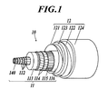
- FIG. 1 is a view showing an example of the superconducting cable.
- a superconducting cable 10 is a single-core superconducting cable in which a single cable core 11 is contained in a thermal insulation tube 12.
- the cable core 11 is configured by including a former 140, a superconductive conductor layer 112 which includes superconducting wires, an electric insulating layer 113, a superconducting shield layer 114, a normal conducting shield layer 115, a protecting layer 116 and such like.
- the former 140 is a winding core for forming the cable core 11, and is formed by twisting a normal conducting wire (conductor line) such as a copper wire, for example. Fault current which flows through the superconductive conductor layer 112 upon short circuit is branched into the former 140.
- the former 140 is formed to be hollow inside and liquid cooling medium (for example, liquid nitrogen) is supplied to the hollow section formed in the hollow part to cool the former 140 and the superconductive conductor layer 112.
- liquid cooling medium for example, liquid nitrogen
- the liquid cooling medium is same as after-mentioned liquid cooling medium which is supplied to the circumference of the cable core 11 in the thermal insulation tube 12.
- the superconductive conductor layer 112 is formed by spirally winding a plurality of superconducting wires via carbon paper (not shown in the drawings) on the former 140.
- the superconductive conductor layer 112 has a laminated structure of four layers. Transmission current is applied to the superconductive conductor layer 112 during a steady operation.
- the superconducting wires forming the superconductive conductor layer 112 have a laminated structure in which an intermediate layer, a superconducting layer and a protecting layer are formed in order on a tape-shaped metal substrate, for example.
- a superconductor forming the superconducting layer a RE-based superconductor (RE: rare earth element) which becomes a superconducting state at a liquid nitrogen temperature or higher can be used.
- a typical RE-based superconductor is an yttrium-based superconductor (Y-based superconductor, hereinafter) which is expressed as the chemical formula YBa 2 Cu 3 O 7-y , for example.
- a tape-shaped superconducting wire in which a superconductor is formed in a metal matrix may be also used.
- a bismuth-based superconductor which is expressed as the chemical formula Bi 2 Sr 2 CaCu 2 O 8+ ⁇ (Bi2212) or Bi 2 Sr 2 Ca 2 Cu 3 O 10+ ⁇ (Bi2223), for example, can be applied.
- the ⁇ in the chemical formula indicates a nonstoichiometric amount of oxygen.
- the electric insulating layer 113 is configured by including a type of insulating paper such as insulating paper, semi-synthesized paper obtained by bonding insulating paper with a polypropylene film, and a polymer non-woven tape, and the electric insulating layer 113 is formed by being wound so as to be laminated on the superconductive conductor layer 112.
- a type of insulating paper such as insulating paper, semi-synthesized paper obtained by bonding insulating paper with a polypropylene film, and a polymer non-woven tape
- the superconducting shield layer 114 is formed by spirally winding a plurality of superconducting wires via carbon paper (not shown in the drawings) on the electric insulating layer 113.
- the superconducting shield layer 114 has a laminated structure of two layers. Electric current which is nearly same as the conductor current is applied to the superconducting shield layer 114 in opposite phase by an electromagnetic induction during a steady operation.
- the superconducting wire forming the superconducting shield layer 114 the same superconducting wire as that of the superconductive conductor layer 112 can be applied.
- the normal conducting shield layer 115 is formed by winding a normal conducting wire such as a copper wire on the superconducting shield layer 114. Fault current which flows through the superconducting shield layer 114 upon short circuit is branched into the normal conducting shield layer 115.
- a protecting layer 116 is configured by including a type of insulating paper such as insulating paper and a polymer non-woven tape, and formed by being wound on the normal conducting shield layer 115, for example.
- the thermal insulation tube 12 has a double tube structure formed by a thermal insulation internal tube 121 which contains the cable core 11 and is filled with cooling medium (for example, liquid nitrogen) and a thermal insulation external tube 122 which is arranged so as to cover the outer circumference of the thermal insulation internal tube 121.
- cooling medium for example, liquid nitrogen
- the thermal insulation internal tube 121 and the thermal insulation external tube 122 are a stainless-steel corrugated tube, for example.
- the outer circumference of the thermal insulation external tube 122 is covered with a corrosion-resistant layer 124 formed by polyvinyl chloride (PVC), polyethylene and such like.
- PVC polyvinyl chloride
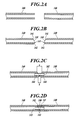
- FIGS. 2A to 2D show connecting operation processes when connecting the formers 140 and 140.
- an end section of the cable core 11 is pulled out from the thermal insulation tube 12, and the superconductive conductor layer 112, the electric insulating layer 113, the superconducting shield layer 114, the normal conducting shield layer 115 and the protecting layer 116 are stripped stepwise to expose a connection end section of the former 140.
- each of the formers 140 and 140 to be connected to each other has the end surface of the connection end section which is formed by a single flat surface perpendicular to the longer direction.
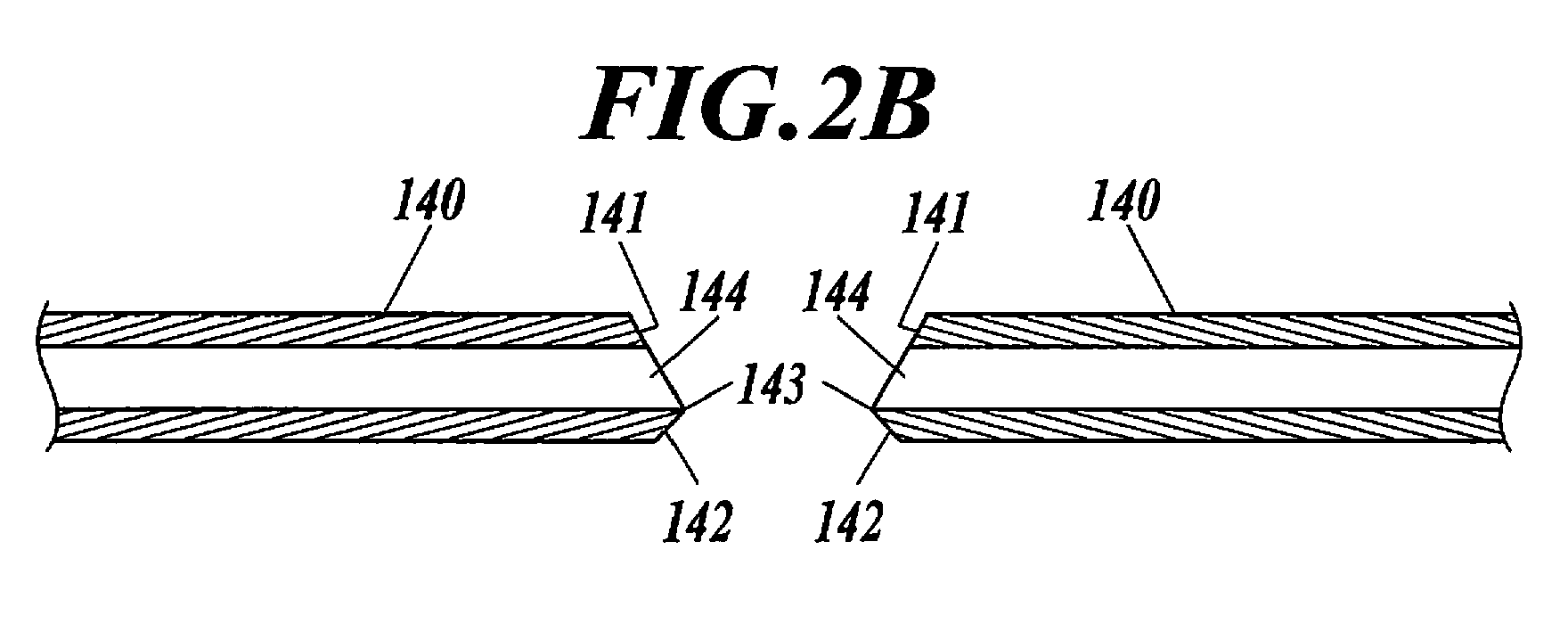
- each of the formers 140 is formed of two inclined surfaces 141 and 142 as shown in FIG. 3 , and each of the formers 140 is pointed-shaped in which a boundary section 143 that is the border of the two inclined surfaces 141 and 142 protrudes toward the other former 140. It is preferable that the entire size of the upper inclined surface 141 is formed to be larger than the lower inclined surface 142 in the vertical direction and the longer direction of the formers 140.
- the formers 140 are formed by twisting a plurality of copper wires as mentioned above, at each of the upper and lower inclined surfaces 141 and 142, the gaps between the copper wires are fixed with a melted copper material so that the copper wires do not separate.
- connection conduit inserting process an end section and the other end section of the connection conduit 145 are inserted into the respective open sections 144 leading to the hollow internal sections in the connection end sections of the formers 140, and the boundary sections 143 and 143 butt against each other to be in an opposed state (connection conduit inserting process). It is desirable that the boundary sections 143 and 143 are in parallel and contact with each other in terms of equal diameter connection; however, the boundary sections 143 and 143 may have a little gap therebetween.
- connection conduit 145 is designed to have an outer diameter which is nearly same as the inner diameter of the hollow formers 140 and can be inserted from the open sections 144.
- the connection conduit 145 is formed of a hollow conductor over the entire length, and it is preferable that the connection conduit 145 is formed of a same material as that of the former 140 in terms of connection compatibility upon welding. Specifically, it is preferable that a copper tubular body is used as the connection conduit 145 when the former 140 is made of copper, and a stainless-steel tubular body is used as the connection conduit 145 when the former 140 is made of stainless-steel.
- connection conduit 145 inserted into the formers 140 has a structure which does not disturb the circulation of liquid cooling medium that flows from the hollow internal section of the one former 140 to the hollow internal section of the other former 140. Accordingly, a connection conduit 145 having a larger inner diameter is desirable; however, it is desirable that the inner diameter is determined while ensuring a predetermined strength since the strength is lowered if the wall of the connection conduit 145 becomes thinner.
- a wedge-shaped gap space is formed between the upper inclined surfaces 141 and 141 and between the lower inclined surfaces 142 and 142 each.
- a desirable maximum open width a (width in the longer direction of former 140) of the upper wedge-shaped gap space is approximately three to four times as large as the maximum open width b of the lower wedge-shaped gap space.
- the maximum open width a is three times as large as the maximum open width b.
- connection end sections of the respective formers 140 are welded by using a welding filler material 146 from above (welding process).
- the welding filler material 146 soldder, copper and such like
- the welding filler material also enters the lower wedge-shaped gap space from between the boundary sections 143 and 143, and as a result, both of the upper wedge-shaped gap space and the lower wedge-shaped gap space are filled with the welding filler material 146.
- connection conduit 145 inhibits the hollow internal sections of the formers 140 from being blocked with the welding filler material 146, and a good communicated state between the hollow internal sections is maintained.
- the bonded part by the welding filler material 146 is polished so as to be equal to the outer diameter of the formers 140 and 140 to remove the excess welding filler material.
- superconducting wires are arranged via carbon paper on the outer circumferential surfaces and the superconducting wires own by the respective cable cores 11 and 11 are connected to each other by soldering to form the superconductive conductor layer 112.
- the insulation paper is wound on the superconductive conductor layer 112 to form the electric insulating layer 113.
- the insulation paper is wound until the outer diameter thereof becomes larger than the original electric insulating layer 113 of the cable core 11.
- the end sections of the cable cores 11 and 11 of the superconducting cables 10 and 10 are connected to each other. Furthermore, the connection part of the cables cores 11 and 11 of the superconducting cables 10 and 10 is stored in a thermal insulation container. Each of the thermal insulation tubes 12 and 12 of the superconducting cables 10 and 10 is connected to the thermal insulation container which contains the connection part.
- liquid cooling medium supplied into the thermal insulation tubes 12 and 12 can circulate via the thermal insulation container, and a cooling means at the connection part of the cable cores 11 and 11 is also secured.
- connection end sections of the formers 140 and 140 are connected to each other by welding using a welding filler material in a state where the hollow connection conduit 145 is inserted into the open sections 144 and 144 leading to the hollow internal sections of the connection end sections of the respective formers 140 and 140, the blockage of the hollow internal sections of the formers 140 and 140 during the connection operation is prevented, enabling the good circulation of the liquid cooling medium for cooling the inside.
- the welding filler material blocks the hollow internal sections of the formers 140 and 140, the whole of the connection end surfaces can be sufficiently bonded, and the bond strength can be improved.
- the welding filler material blocks the hollow internal sections of the formers 140 and 140, the bonding operation can be easily performed and the workability can also be improved.
- the formers 140 and 140 are connected to each other by providing a tubular member outside them, since the convex portion is not generated on the outer circumferential surface of each of the formers 140 and 140, the stress of the superconductive conductor layer 112 to the superconducting wires due to the convex portion on the surface of the former 140 is resolved, and durability and reliability of the superconducting wires can be improved. Also, even in a case where a large current is applied, it is possible to avoid the concentration of the electric field at the angular portion of the tubular conductor and maintain a good insulation property.
- the smaller wedge-shaped gap made by the inclined surfaces 142 and 142 is also filled with the welding filler material, and it is possible to spread the welding filler material throughout the connection end sections, bond them firmly and improve the bonding workability.
- the welding filler material moves from the large wedge-shaped gap to the small wedge-shaped gap at the lower side, and the small wedge-shaped gap can also be filled with the welding filler material without deficiency and excess.
- each of the formers 140 and 140 is formed by binding conductor (copper) wires
- the formers 140 and 140 themselves can have a high flexibility, the connection end sections thereof also easily butt against each other, and thus the workability can be improved.
- a preferable material used for the fixing is the same material as the material of the conductor wires in terms of suppressing unevenness of electrical performance at the connection part after welding.
- FIG. 4A shows a case where the two inclined surfaces 141 and 142 have a same inclination angle with respect to the longer direction of the former 140 and the inclination angle is small
- FIG. 4B shows a case where the two inclined surfaces 141 and 142 have a same inclination angle with respect to the longer direction of the former 140 and the inclination angle is a little larger than that of FIG. 4A .
- connection conduit 145 prevents the hollow internal section of each of the formers 140 and 140 from being blocked, and thus connection can be made maintaining firm and good insulation property, and in addition, the workability can be improved.
- the welding filler material can fill the lower wedge-shaped gap from the upper wedge-shaped gap, and the workability of the bonding can also be improved.
- bonding may be performed by forming an end surface which is formed of the inclined surface 141 and a vertical surface 147 vertical to the longer direction of the former at the connection end section of each of the formers 140 and 140, forming a wedge-shaped gap by the inclined surfaces 141 and 141 and a parallel gap by the vertical surfaces 147 and 147 as an arrangement for matching the inclined surfaces 141 and 141 to each other, and filling the wedge-shaped gap which is directed upward.
- connection conduit 145 prevents the blockage of the hollow internal section of each of the formers 140 and 140, and thus connection can be made maintaining firm and good insulation property, and in addition, the workability can be improved.
- the welding filler material filling the wedge-shaped gap also flows into the parallel gap to fill the gap, and the workability of the bonding can be improved.
- the parallel gap can be filled with the welding filler material without deficiency and excess. Accordingly, it is possible to inhibit the protrusion of the welding filler material outside due to excess filling with the welding filler material to the lower gap and eliminate the need of removal operation and such like of excess welding filler material while enhancing the bond strength.
- bonding may be performed by forming only an end surface formed of a single inclined surface 141 at the connection end section of each of the formers 140 and 140 and filling the wedge-shaped gap made by the inclined surfaces 141 and 141 which is directed upward with the welding filler material.
- connection conduit 145 inhibits the blockage of the hollow internal section of each of the formers 140 and 140, connection can be made maintaining firm and good insulation property, and workability can also be improved.
- the man-hour of the connection operation can be reduced; however, since only the wedge-shaped gap is formed between the connection end sections of the formers 140 and 140, the bonding operation needs to be performed while adjusting the filling amount of the welding filler material so that the filled welding filler material does not leak downward.
- connection end section of each of the formers 140 and 140 may have only an end surface vertical to the longer direction of the former to connect the connection end sections of the formers 140 and 140 to each other by the connection conduit 145.
- an end section of the connection conduit 145 is inserted to the open section 144 of the one former 140, fixing is performed by welding therebetween, and thereafter, the other end section of the connection conduit 145 is inserted into the open section 144 of the other former 140, and the opposed end surfaces of the formers 140 and 140 are connected by welding.
- a detachable insertion auxiliary tool 148 which fits to a concave portion formed at the outer circumferential surface section of the connection conduit 145 may be used to perform insertion operation of the connection conduit 145 into the open sections 144 and 144 (see FIG. 2B ) of the formers 140 and 140.
- the insertion auxiliary tool 148 is attached while extending from the outer circumferential surface of the connection conduit 145 to the outside in the radial direction thereof, and when inserting the connection conduit 145 into the open sections 144 and 144 of the respective formers 140 and 140, the insertion auxiliary tool 148 protrudes outside from a gap (for example, a wedge-shaped gap) between the end surfaces at the connection end sections of the respective formers 140 and 140, and by operating the insertion auxiliary tool 148, the connection conduit 145 can be adjusted to an appropriate position in the longer direction of the former 140.
- a gap for example, a wedge-shaped gap
- the insertion auxiliary tool 148 Since the insertion auxiliary tool 148 is detachable from the connection conduit 145, the insertion auxiliary tool 148 can be detached to be removed when the insertion process of the connection conduit 145 is completed. Accordingly, at the welding operation, the operation can be performed in a state where the insertion auxiliary tool 148 is removed. Since the insertion auxiliary tool 148 is not left attached to the former 140, it does not disturb the formation of the superconductive conductor layer 112 on the outer circumference of the former 140.
- the formers 140 having the same shape of the connection end sections as that of FIG. 5 is illustrated; however, the formers 140 are not limited to this, and the example shown in FIG. 7 can be utilized for connection operation of any of the formers 140 in FIGS. 2C , 4A , 4B and 6 .
- the present invention has an applicability at a field of superconducting cable in which a former is hollow and cooling is performed therein at cryogenic temperatures.
Landscapes
- Physics & Mathematics (AREA)
- Condensed Matter Physics & Semiconductors (AREA)
- General Physics & Mathematics (AREA)
- Engineering & Computer Science (AREA)
- Manufacturing & Machinery (AREA)
- Superconductors And Manufacturing Methods Therefor (AREA)
- Gas Or Oil Filled Cable Accessories (AREA)
- Connections Effected By Soldering, Adhesion, Or Permanent Deformation (AREA)
- Manufacturing Of Electrical Connectors (AREA)
- Processing Of Terminals (AREA)
Abstract


Description
- The present invention relates to a structure and a method for connecting formers located at centers of cable cores of superconducting cables.
- A superconducting cable includes a cable core which has a former and a superconducting wire and a thermal insulation tube which has a vacuum double tube structure to contain the cable core, and liquid cooling medium of ultralow temperature is circulated to cool the cable core inside the thermal insulation tube.
- Then, in order to enhance the cooling efficiency of the superconducting wire and the former, the former is formed to be hollow and the liquid cooling medium is circulated also inside the hollow section.
- In a case where the superconducting cable is used as a power supply line, the superconducting cable needs to be laid out from the power supply source to the distant power-consuming area; however, the superconducting cable has a limitation in length of single cable for manufacturing or logistic reasons. Thus, when performing long-distance cable laying, many superconducting cables need to be connected at the laying site.
- Then, when connecting end sections of formers of the superconducting cables, a method of making the distal end sections butt against each other and connecting them by welding (for example, see Patent document 1), a method of inserting the respective formers through the both ends of a tubular conductor and swaging from outside to connect them (for example, see Patent document 2) and such like have been adopted.
- In addition, as a method for connecting the joints of the hollow conductor, there is known a method of arranging a reinforcing pipe on the outer circumference of the hollow conductor and connecting the hollow conductor to the reinforcing pipe by brazing (Patent document 3).
-
- Patent Document 1: Japanese Patent Application Laid Open Publication No.
2009-136071 - Patent Document 2: Japanese Patent Application Laid Open Publication No.
2006-302674 - Patent Document 3: Japanese Patent Application Laid Open Publication No.
H07-42882 - However, when the distal end sections of the hollow formers butt against each other to be welded, the hollow sections are blocked or narrowed in some cases since a welding filler material used for the welding flows into the hollow sections, and thus the circulation of a cooling medium is disturbed and the cables cannot be cooled sufficiently in some cases. There is also a problem that if the welding is performed so as not to block the hollow internal sections of the formers, the welding cannot be performed up to near the hollow internal sections, and thus the welding strength becomes low or the process operation itself is troublesome to worsen the workability.
- Also, when the formers are connected by swaging or brazing using the tubular conductor, there have been problems such that the contact condition therebetween is insufficient and the electric conductivity becomes worse, or an angular portion of the tubular conductor contacts the superconducting wires arranged outside the formers to cause a stress and electric field is concentrated at the angular portion of the tubular conductor to lower the insulation property.
- An object of the present invention is to provide a structure and a method for connecting superconducting cables which maintains an internal hollow state of formers and enables good electrical transmission of superconductive conductor layers.
- The present invention is a connection structure of formers for connecting hollow formers provided inside superconducting cables, wherein one end section and the other end section of a hollow connection conduit are inserted into open sections leading to hollow internal sections formed at connection end sections of the respective formers, and the opposed connection end sections of the respective formers are connected to each other by welding.
- The connection structure according to the present invention may have a configuration in which a connection end section of each of the formers is formed of an end surface including an inclined surface which is inclined with respect to a longer direction of each of the formers, and corresponding inclined surfaces at the connection end sections of the respective formers are opposed to each other so as to form a wedge-shaped gap, and opposed end surfaces are connected to each other with a welding filler material.
- The connection structure according to the present invention may have a configuration in which each of the end surfaces includes two inclined surfaces, one being large and the other being small, among two wedge-shaped gaps, one being a large wedge-shaped gap and the other being a small wedge-shaped gap, which are formed by the inclined surfaces between the opposed connection end sections of the respective formers, the large wedge-shaped gap is located at an upper side and the small wedge-shaped gap is located at a lower side, and each of the gaps is filled with the welding filler material.
- The connection structure according to the present invention may have a configuration in which a maximum open width of the large wedge-shaped gap in the longer direction of the formers is three times or more as large as a maximum open width of the small wedge-shaped gap in the longer direction of the formers.
- The connection structure according to the present invention may have a configuration in which each of the formers is formed by binding conductor wires, and at the connection end section, the conductor wires are integrally bonded.
- The present invention is a connection method of formers for connecting hollow formers provided inside superconducting cables, including inserting one end section and the other end section of a hollow connection conduit into open sections leading to hollow internal sections formed at connection end sections of the respective formers; and connecting the opposed connection end sections of the respective formers to each other by welding.
- The connection method according to present invention may have a configuration which includes forming, at a connection end section of each of the formers, an end surface which includes an inclined surface that is inclined with respect to a longer direction of each of the formers, and in which, in the connecting by the welding, corresponding inclined surfaces at the connection end sections of the respective formers are opposed to each other so as to form a wedge-shaped gap, and a welding filler material is filled between opposed end surfaces.
- The connection method according to the present invention may have a configuration which includes providing the connection conduit with a detachable insertion auxiliary tool which is used while extending outside in a radial direction from an outer circumferential surface of the connection conduit and in which in the inserting of the one end section and the other end section of the connection conduit, an insertion operation of the connection conduit into the open sections of the respective formers is performed in a state where the insertion auxiliary tool is extending outside from between the opposed end surfaces of the respective connection end sections, and the insertion auxiliary tool is removed after the inserting.
- The connection method according to the present invention may have a configuration in which in the forming of the end surface including the inclined surface, an end surface formed of two inclined surfaces, one being large and the other being small, is formed at the connection end section of each of the formers, and in the connecting by the welding, among two wedge-shaped gaps, one being a large wedge-shaped gap and the other being a small wedge-shaped gap, which are formed by the inclined surfaces between the opposed connection end sections of the respective formers, the large wedge-shaped gap is located at an upper side, the small wedge-shaped gap is located at a lower side, and each of the gaps is filled with the welding filler material.
- The connection method according to the present invention may have a configuration including binding wires to form each of the formers and integrally bonding the wires at the connection end section.
- The present invention enables good circulation of liquid cooling medium for cooling the internal sections since connection end sections of formers are connected to each other by welding in a state where a hollow connection conduit is inserted into open sections leading to hollow internal sections in connection end sections of the respective formers. Furthermore, existence of the connection conduit eliminates the concern that the hollow internal sections of the formers may be blocked, and thus, the bonding can be performed sufficiently to the entire surfaces of the connection ends and the bond strength can be improved.
- In addition, by using the connection conduit at the bonding operation, blockage of the hollow internal sections of formers due to deformation of members forming the formers is prevented. Furthermore, since the existence of the connection conduit eliminates the concern about the blockage of the hollow internal sections of formers, the bonding operation can be performed easily and the workability can also be improved.
- Then, different from a case where a tubular member is provided outside the formers, a convex portion is not generated around the outer circumferential surface of the formers, and thus, it is possible to eliminate a stress which is caused when superconducting wires are arranged around the outer circumference and improve durability and reliability. It is also possible to avoid the concentration of electric field in the superconducting wires and maintain a good insulation property even when a large electric current is applied.
- In a case where end surfaces are connected to each other by a welding filler material in a state where inclined surfaces corresponding to the connection end sections of the opposed formers form a wedge-shaped gap, it is possible to easily spread the welding filler material throughout the opposed end surfaces of the formers facing each other to provide strong bonding and improve the workability.
- In a case where two wedge-shaped gaps, one being large and the other being small, are formed between the connection end sections of the opposed formers with the large one provided at the upper side, when the large wedge-shaped gap is filled with the welding filler material, the wedge-shaped gap at the lower side is filled even when the welding filler material leaks downward, and it is possible to inhibit the welding filler material from being convex on the outer circumferential surface of the formers. Thus, the bonding operation can be easily performed and the workability can be improved.
- Also, in a case where the large wedge-shaped gap has the maximum open width in the longer direction of the former which is three times or more as large as the maximum open width in the longer direction of the former of the small wedge-shaped gap, when the welding filler material moves from the large wedge-shaped gap to the small wedge-shaped gap located at the lower side, the small wedge-shaped gap can be sufficiently filled with the welding filler material.
- In a case where the formers are formed by binding conductor wires, the formers themselves can have a high flexibility and the respective connection end sections can also easily butt against each other, and thus the workability can be improved.
- In addition, since the wires are integrally bonded at each of the connection end sections, the conductor wires forming each of the formers do not separate at the bonding operation, the bonding operation is facilitated, the bonding strength can be enhanced, and furthermore, the connection resistance can also be lowered by the cross-section being integrated.
- In a case where the connection conduit includes an insertion auxiliary tool which is extending from the outer circumferential surface to the outside in the radial direction thereof, the connection conduit can be inserted by using the insertion auxiliary tool, and thus the workability of the connection operation can be improved. Since the insertion auxiliary tool is detachable from the connection conduit and can be removed after the insertion operation, the operation thereafter is not disturbed and the workability is improved also in this respect.
-
-
FIG. 1 is a perspective view showing a structure of a superconducting cable. -
FIG. 2A is a view showing a first connection operation process when connecting formers. -
FIG. 2B is a view showing a connection operation process followingFIG. 2A when connecting the formers. -
FIG. 2C is a view showing a connection process followingFIG. 2B when connecting the formers. -
FIG. 2D is a view showing connection operation process followingFIG. 2C when connecting the formers. -
FIG. 3 is a view of a connection end section of one of the formers inFIG. 2B seen from the other former side. -
FIG. 4A is a view showing an example of a case where inclined surfaces which have a same size are vertically formed at the connection end section of each of the formers. -
FIG. 4B is a view showing an example of a case where same inclined surfaces which have an inclination angle larger than that ofFIG. 4A are vertically formed at the connection end section of each of the formers. -
FIG. 5 is a view showing an example of a case where an end surface formed of an inclined surface and a non-inclined surface is formed at the connection end section of each of the formers. -
FIG. 6 is a view showing an example of a case where an end surface formed of only one inclined surface is formed at the connection end section of each of the formers. -
FIG. 7 is a view showing an example where the connection conduit is inserted into an open section of each of the formers by using the insertion auxiliary tool. - Hereinafter, an embodiment of the present invention will be described in detail on the basis of the drawings.
-
FIG. 1 is a view showing an example of the superconducting cable. - A
superconducting cable 10 is a single-core superconducting cable in which asingle cable core 11 is contained in athermal insulation tube 12. Thecable core 11 is configured by including a former 140, asuperconductive conductor layer 112 which includes superconducting wires, an electric insulatinglayer 113, asuperconducting shield layer 114, a normalconducting shield layer 115, aprotecting layer 116 and such like. - The former 140 is a winding core for forming the
cable core 11, and is formed by twisting a normal conducting wire (conductor line) such as a copper wire, for example. Fault current which flows through thesuperconductive conductor layer 112 upon short circuit is branched into the former 140. - The former 140 is formed to be hollow inside and liquid cooling medium (for example, liquid nitrogen) is supplied to the hollow section formed in the hollow part to cool the former 140 and the
superconductive conductor layer 112. The liquid cooling medium is same as after-mentioned liquid cooling medium which is supplied to the circumference of thecable core 11 in thethermal insulation tube 12. - The
superconductive conductor layer 112 is formed by spirally winding a plurality of superconducting wires via carbon paper (not shown in the drawings) on the former 140. InFIG. 1 , thesuperconductive conductor layer 112 has a laminated structure of four layers. Transmission current is applied to thesuperconductive conductor layer 112 during a steady operation. - The superconducting wires forming the
superconductive conductor layer 112 have a laminated structure in which an intermediate layer, a superconducting layer and a protecting layer are formed in order on a tape-shaped metal substrate, for example. As a superconductor forming the superconducting layer, a RE-based superconductor (RE: rare earth element) which becomes a superconducting state at a liquid nitrogen temperature or higher can be used. A typical RE-based superconductor is an yttrium-based superconductor (Y-based superconductor, hereinafter) which is expressed as the chemical formula YBa2Cu3O7-y, for example. A tape-shaped superconducting wire in which a superconductor is formed in a metal matrix may be also used. As the superconductor, a bismuth-based superconductor which is expressed as the chemical formula Bi2Sr2CaCu2O8+δ (Bi2212) or Bi2Sr2Ca2Cu3O10+δ (Bi2223), for example, can be applied. - The δ in the chemical formula indicates a nonstoichiometric amount of oxygen.
- The electric
insulating layer 113 is configured by including a type of insulating paper such as insulating paper, semi-synthesized paper obtained by bonding insulating paper with a polypropylene film, and a polymer non-woven tape, and the electric insulatinglayer 113 is formed by being wound so as to be laminated on thesuperconductive conductor layer 112. - The
superconducting shield layer 114 is formed by spirally winding a plurality of superconducting wires via carbon paper (not shown in the drawings) on the electric insulatinglayer 113. InFIG. 1 , thesuperconducting shield layer 114 has a laminated structure of two layers. Electric current which is nearly same as the conductor current is applied to thesuperconducting shield layer 114 in opposite phase by an electromagnetic induction during a steady operation. As the superconducting wire forming thesuperconducting shield layer 114, the same superconducting wire as that of thesuperconductive conductor layer 112 can be applied. - The normal
conducting shield layer 115 is formed by winding a normal conducting wire such as a copper wire on thesuperconducting shield layer 114. Fault current which flows through thesuperconducting shield layer 114 upon short circuit is branched into the normalconducting shield layer 115. - A protecting
layer 116 is configured by including a type of insulating paper such as insulating paper and a polymer non-woven tape, and formed by being wound on the normalconducting shield layer 115, for example. - The
thermal insulation tube 12 has a double tube structure formed by a thermal insulationinternal tube 121 which contains thecable core 11 and is filled with cooling medium (for example, liquid nitrogen) and a thermal insulationexternal tube 122 which is arranged so as to cover the outer circumference of the thermal insulationinternal tube 121. - The thermal insulation
internal tube 121 and the thermal insulationexternal tube 122 are a stainless-steel corrugated tube, for example. A multilayer thermal insulator (Super Insulation) 123 formed by a laminated body of polyethylene film which is vapor-deposited with aluminum, for example, intervenes between the thermal insulationinternal tube 121 and the thermal insulationexternal tube 122 to be held in a vacuum state. Also, the outer circumference of the thermal insulationexternal tube 122 is covered with a corrosion-resistant layer 124 formed by polyvinyl chloride (PVC), polyethylene and such like. - In a case where cables are laid out over a long distance, end sections of a plurality of
superconducting cables 10 are connected to each other via known intermediate connecting parts. In the embodiment, a connection structure for connectingformers superconducting cables -
FIGS. 2A to 2D show connecting operation processes when connecting theformers superconducting cables cable core 11 is pulled out from thethermal insulation tube 12, and thesuperconductive conductor layer 112, the electric insulatinglayer 113, thesuperconducting shield layer 114, the normalconducting shield layer 115 and theprotecting layer 116 are stripped stepwise to expose a connection end section of the former 140. - As shown in
FIG. 2A , at first, each of theformers - Then, as shown in
FIG. 2B , two inclined surfaces are formed at the connection end section of each of the formers 140 (inclined surface forming process). The end surface of the connection end section of each of theformers 140 is formed of twoinclined surfaces FIG. 3 , and each of theformers 140 is pointed-shaped in which aboundary section 143 that is the border of the twoinclined surfaces inclined surface 141 is formed to be larger than the lowerinclined surface 142 in the vertical direction and the longer direction of theformers 140. - Since the
formers 140 are formed by twisting a plurality of copper wires as mentioned above, at each of the upper and lowerinclined surfaces - Then, as shown in
FIG. 2C , an end section and the other end section of theconnection conduit 145 are inserted into the respectiveopen sections 144 leading to the hollow internal sections in the connection end sections of theformers 140, and theboundary sections boundary sections boundary sections - The
connection conduit 145 is designed to have an outer diameter which is nearly same as the inner diameter of thehollow formers 140 and can be inserted from theopen sections 144. Theconnection conduit 145 is formed of a hollow conductor over the entire length, and it is preferable that theconnection conduit 145 is formed of a same material as that of the former 140 in terms of connection compatibility upon welding. Specifically, it is preferable that a copper tubular body is used as theconnection conduit 145 when the former 140 is made of copper, and a stainless-steel tubular body is used as theconnection conduit 145 when the former 140 is made of stainless-steel. Theconnection conduit 145 inserted into theformers 140 has a structure which does not disturb the circulation of liquid cooling medium that flows from the hollow internal section of the one former 140 to the hollow internal section of the other former 140. Accordingly, aconnection conduit 145 having a larger inner diameter is desirable; however, it is desirable that the inner diameter is determined while ensuring a predetermined strength since the strength is lowered if the wall of theconnection conduit 145 becomes thinner. - Then, when the connection end sections of the
formers boundary sections inclined surfaces inclined surfaces inclined surfaces - Next, as shown in
FIG. 2D , the connection end sections of therespective formers 140 are welded by using awelding filler material 146 from above (welding process). At this time, when the upper wedge-shaped gap space is filled with the welding filler material 146 (solder, copper and such like), the welding filler material also enters the lower wedge-shaped gap space from between theboundary sections welding filler material 146. - Thus, the whole range of the exposed outer circumferential surface of the
connection conduit 145, the upperinclined surfaces inclined surfaces welding filler material 146, and the connection end sections of theformers connection conduit 145 inhibits the hollow internal sections of theformers 140 from being blocked with thewelding filler material 146, and a good communicated state between the hollow internal sections is maintained. - In a case where the
welding filler material 146 protrudes outside the upper and lower wedge-shaped gap space, it is preferable that the bonded part by thewelding filler material 146 is polished so as to be equal to the outer diameter of theformers - After connecting the
formers respective cable cores respective cable cores superconductive conductor layer 112. - Then, the insulation paper is wound on the
superconductive conductor layer 112 to form the electric insulatinglayer 113. At this time, since the insulation property needs to be more enhanced for the connection end of the superconducting wires which are connected by soldering, the insulation paper is wound until the outer diameter thereof becomes larger than the original electric insulatinglayer 113 of thecable core 11. - Then, superconducting wires to be connected to each other by soldering are arranged on the electric insulating
layer 113, thesuperconducting shield layer 114 is formed, and further on top of them, the normalconducting shield layer 115 and theprotecting layer 116 are formed. - Thus, the end sections of the
cable cores superconducting cables cables cores superconducting cables thermal insulation tubes superconducting cables - As a result, liquid cooling medium supplied into the
thermal insulation tubes cable cores - In such way, when connecting the
cable cores superconducting cables formers hollow connection conduit 145 is inserted into theopen sections respective formers formers - Also, since there is no concern that the welding filler material blocks the hollow internal sections of the
formers formers - Furthermore, different from a case where the
formers formers superconductive conductor layer 112 to the superconducting wires due to the convex portion on the surface of the former 140 is resolved, and durability and reliability of the superconducting wires can be improved. Also, even in a case where a large current is applied, it is possible to avoid the concentration of the electric field at the angular portion of the tubular conductor and maintain a good insulation property. - Furthermore, between the opposed connection end sections of the
formers inclined surfaces inclined surfaces - At that time, in a case where the maximum open width a of the large wedge-shaped gap in the longer direction of the former 140 is three times the maximum open width b of the small wedge-shaped gap, the welding filler material moves from the large wedge-shaped gap to the small wedge-shaped gap at the lower side, and the small wedge-shaped gap can also be filled with the welding filler material without deficiency and excess.
- In a case where each of the
formers formers - In addition, by integrally bonding the wires at each of the connection end sections, the conductor wires forming the former 140 do not separate during the bonding operation, and thus, the bonding operation is facilitated and the bond strength can be enhanced. When integrally bonding wires at each of the connection end sections, a preferable material used for the fixing is the same material as the material of the conductor wires in terms of suppressing unevenness of electrical performance at the connection part after welding.
- In the above connection structure of the
formers inclined surfaces FIGS.4A and 4B. FIG. 4A shows a case where the twoinclined surfaces FIG. 4B shows a case where the twoinclined surfaces FIG. 4A . - Also in the cases, the
connection conduit 145 prevents the hollow internal section of each of theformers - Furthermore, upon welding, the welding filler material can fill the lower wedge-shaped gap from the upper wedge-shaped gap, and the workability of the bonding can also be improved.
- Also, as shown in
FIG. 5 , bonding may be performed by forming an end surface which is formed of theinclined surface 141 and avertical surface 147 vertical to the longer direction of the former at the connection end section of each of theformers inclined surfaces vertical surfaces inclined surfaces - Also in this case, the
connection conduit 145 prevents the blockage of the hollow internal section of each of theformers - Furthermore, by directing the wedge-shaped gap upward, the welding filler material filling the wedge-shaped gap also flows into the parallel gap to fill the gap, and the workability of the bonding can be improved. Also, different from the cases of
FIGS. 4A and 4B , since the volume of the parallel gap is smaller than that of the wedge-shaped gap, the parallel gap can be filled with the welding filler material without deficiency and excess. Accordingly, it is possible to inhibit the protrusion of the welding filler material outside due to excess filling with the welding filler material to the lower gap and eliminate the need of removal operation and such like of excess welding filler material while enhancing the bond strength. - Since only a single
inclined surface 141 is formed at the former 140, the man-hour of the connecting operation can be reduced. - As shown in
FIG. 6 , bonding may be performed by forming only an end surface formed of a singleinclined surface 141 at the connection end section of each of theformers inclined surfaces - Also in this case, the
connection conduit 145 inhibits the blockage of the hollow internal section of each of theformers - Also in this case, since the only one
inclined surface 141 is formed, the man-hour of the connection operation can be reduced; however, since only the wedge-shaped gap is formed between the connection end sections of theformers - Though not shown in the drawings, the connection end section of each of the
formers formers connection conduit 145. In such case, an end section of theconnection conduit 145 is inserted to theopen section 144 of the one former 140, fixing is performed by welding therebetween, and thereafter, the other end section of theconnection conduit 145 is inserted into theopen section 144 of the other former 140, and the opposed end surfaces of theformers - In this case, since a wedge-shaped gap space made by an inclined surface is not formed, filling of the space with the welding filler material is not necessary, and thus it is also possible to perform welding by melting a part of the members of the
formers connection conduit 145 without using the welding filler material. It is also possible to perform welding by using a small amount of welding filler material. - As shown in
FIG. 7 , a detachable insertionauxiliary tool 148 which fits to a concave portion formed at the outer circumferential surface section of theconnection conduit 145 may be used to perform insertion operation of theconnection conduit 145 into theopen sections 144 and 144 (seeFIG. 2B ) of theformers auxiliary tool 148 is attached while extending from the outer circumferential surface of theconnection conduit 145 to the outside in the radial direction thereof, and when inserting theconnection conduit 145 into theopen sections respective formers auxiliary tool 148 protrudes outside from a gap (for example, a wedge-shaped gap) between the end surfaces at the connection end sections of therespective formers auxiliary tool 148, theconnection conduit 145 can be adjusted to an appropriate position in the longer direction of the former 140. - Since the insertion
auxiliary tool 148 is detachable from theconnection conduit 145, the insertionauxiliary tool 148 can be detached to be removed when the insertion process of theconnection conduit 145 is completed. Accordingly, at the welding operation, the operation can be performed in a state where the insertionauxiliary tool 148 is removed. Since the insertionauxiliary tool 148 is not left attached to the former 140, it does not disturb the formation of thesuperconductive conductor layer 112 on the outer circumference of the former 140. - In
FIG. 7 , theformers 140 having the same shape of the connection end sections as that ofFIG. 5 is illustrated; however, theformers 140 are not limited to this, and the example shown inFIG. 7 can be utilized for connection operation of any of theformers 140 inFIGS. 2C ,4A ,4B and6 . - The present invention has an applicability at a field of superconducting cable in which a former is hollow and cooling is performed therein at cryogenic temperatures.
-
- 10
- superconducting cable
- 11
- cable core
- 12
- thermal insulation tube
- 112
- superconductive conductor layer
- 113
- electric insulating layer
- 114
- superconducting shield layer
- 115
- normal conducting shield layer
- 116
- protecting layer
- 140
- former
- 141, 142
- inclined surface
- 144
- open section
- 145
- connection conduit
- 146
- welding filler material
- 147
- vertical surface
- 148
- insertion auxiliary tool
Claims (10)
- A connection structure of formers for connecting hollow formers provided inside superconducting cables, comprising:a connection conduit which is hollow,whereinone end section and the other end section of the connection conduit are inserted into open sections leading to hollow internal sections formed at connection end sections of the respective formers, andthe opposed connection end sections of the respective formers are connected to each other by welding.
- The connection structure of the formers according to claim 1,
wherein
a connection end section of each of the formers is formed of an end surface including an inclined surface which is inclined with respect to a longer direction of each of the formers, and
corresponding inclined surfaces at the connection end sections of the respective formers are opposed to each other so as to form a wedge-shaped gap, and opposed end surfaces are connected to each other with a welding filler material. - The connection structure of the formers according to claim 2, wherein
each of the end surfaces includes two inclined surfaces, one being large and the other being small,
among two wedge-shaped gaps, one being a large wedge-shaped gap and the other being a small wedge-shaped gap, which are formed by the inclined surfaces between the opposed connection end sections of the respective formers, the large wedge-shaped gap is located at an upper side and the small wedge-shaped gap is located at a lower side, and each of the gaps is filled with the welding filler material. - The connection structure of the formers according to claim 3, wherein
a maximum open width of the large wedge-shaped gap in the longer direction of the formers is three times or more as large as a maximum open width of the small wedge-shaped gap in the longer direction of the formers. - The connection structure of the formers according to any one of claims 1 to 4, wherein
each of the formers is formed by binding conductor wires, and at the connection end section, the conductor wires are integrally bonded. - A connection method of formers for connecting hollow formers provided inside superconducting cables, comprising:inserting one end section and the other end section of a hollow connection conduit into open sections leading to hollow internal sections formed at connection end sections of the respective formers; andconnecting the opposed connection end sections of the respective formers to each other by welding.
- The connection method of the formers according to claim 6, further comprising:forming, at a connection end section of each of the formers, an end surface which includes an inclined surface that is inclined with respect to a longer direction of each of the formers,wherein,in the connecting by the welding, corresponding inclined surfaces at the connection end sections of the respective formers are opposed to each other so as to form a wedge-shaped gap, and a welding filler material is filled between opposed end surfaces.
- The connection method of the formers according to claim 7, further comprising:providing the connection conduit with a detachable insertion auxiliary tool which is used while extending outside in a radial direction from an outer circumferential surface of the connection conduit,whereinin the inserting of the one end section and the other end section of the connection conduit, an insertion operation of the connection conduit into the open sections of the respective formers is performed in a state where the insertion auxiliary tool is extending outside from between the opposed end surfaces of the respective connection end sections, and the insertion auxiliary tool is removed after the inserting.
- The connection method of the formers according to claim 7 or 8, wherein
in the forming of the end surface including the inclined surface, an end surface formed of two inclined surfaces, one being large and the other being small, is formed at the connection end section of each of the formers, and
in the connecting by the welding, among two wedge-shaped gaps, one being a large wedge-shaped gap and the other being a small wedge-shaped gap, which are formed by the inclined surfaces between the opposed connection end sections of the respective formers, the large wedge-shaped gap is located at an upper side, the small wedge-shaped gap is located at a lower side, and each of the gaps is filled with the welding filler material. - The connection method of the formers according to any one of claims 6 to 9, further comprising:binding wires to form each of the formers and integrally bonding the wires at the connection end section.
Applications Claiming Priority (2)
| Application Number | Priority Date | Filing Date | Title |
|---|---|---|---|
| JP2012123861 | 2012-05-31 | ||
| PCT/JP2013/051812 WO2013179686A1 (en) | 2012-05-31 | 2013-01-29 | Structure and method for connecting former of superconducting cable |
Publications (2)
| Publication Number | Publication Date |
|---|---|
| EP2728687A1 true EP2728687A1 (en) | 2014-05-07 |
| EP2728687A4 EP2728687A4 (en) | 2015-01-21 |
Family
ID=49672902
Family Applications (1)
| Application Number | Title | Priority Date | Filing Date |
|---|---|---|---|
| EP13797579.3A Withdrawn EP2728687A4 (en) | 2012-05-31 | 2013-01-29 | STRUCTURE AND METHOD FOR CONNECTING A SUPERCONDUCTING CABLE SLEEVE |
Country Status (5)
| Country | Link |
|---|---|
| US (1) | US20150107867A1 (en) |
| EP (1) | EP2728687A4 (en) |
| JP (1) | JP6062378B2 (en) |
| CN (1) | CN103733453B (en) |
| WO (1) | WO2013179686A1 (en) |
Families Citing this family (7)
| Publication number | Priority date | Publication date | Assignee | Title |
|---|---|---|---|---|
| CN104134921B (en) * | 2014-07-17 | 2016-04-20 | 华北电力大学 | The method of attachment of a kind of cold insulation high-temperature superconductive cable end conductor |
| CN104134953B (en) * | 2014-07-17 | 2016-07-27 | 华北电力大学 | A kind of hyperconductive cable skeleton connection structure and method of attachment |
| US10317485B2 (en) * | 2016-10-28 | 2019-06-11 | General Electric Company | System and method for magnetic resonance imaging one or more subjects |
| US20190145570A1 (en) * | 2017-11-16 | 2019-05-16 | Saudi Arabian Oil Company | Corrosion-resistant piping and methods of manufacturing and using the same |
| CN108321556B (en) * | 2017-12-11 | 2020-01-31 | 北京交通大学 | Welding device for superconducting cable joint |
| CN108711802B (en) * | 2018-04-09 | 2024-01-09 | 深圳市沃尔核材股份有限公司 | A method of connecting two vertical connecting pipes |
| CN119069176B (en) * | 2024-11-05 | 2025-02-25 | 清华大学 | A high-temperature superconducting unit, a joint and a method for preparing a high-temperature superconducting joint |
Family Cites Families (20)
| Publication number | Priority date | Publication date | Assignee | Title |
|---|---|---|---|---|
| US2125324A (en) * | 1935-04-01 | 1938-08-02 | Karl D Williams | Method of and coupling for pressure pipes |
| US2646995A (en) * | 1948-09-10 | 1953-07-28 | Roland J Thompson | Brazed joint with backing ring |
| US2963129A (en) * | 1954-12-09 | 1960-12-06 | Babcock & Wilcox Co | Dissimilar metal welded joint with protective overlay |
| US3032870A (en) * | 1959-06-18 | 1962-05-08 | North American Aviation Inc | Brazed joint and fabrication method |
| US3895432A (en) * | 1973-07-04 | 1975-07-22 | Siemens Ag | Method of electrically joining together two bimetal tubular superconductors |
| ES2106952T3 (en) * | 1992-05-07 | 1997-11-16 | Conri Rohrverbindungstechnik R | PIPE JOINT AS WELDING HOSE FOR A PIPE JOINT OF THIS TYPE. |
| JPH08138768A (en) * | 1994-11-14 | 1996-05-31 | Sumitomo Electric Ind Ltd | Superconducting cable joint |
| JPH11121059A (en) * | 1997-10-20 | 1999-04-30 | Fujikura Ltd | Intermediate connection for superconducting cable |
| BRPI0411204B1 (en) * | 2003-07-21 | 2015-04-14 | Grant Prideco Lp | Tubular Component Device and Connector and Method for Soldering a Tubular Component and a Connector |
| KR100496995B1 (en) * | 2003-09-29 | 2005-06-23 | 엘에스전선 주식회사 | Jointing structure and jointing method for superconducting cable |
| JP4609842B2 (en) * | 2004-11-30 | 2011-01-12 | 古河電気工業株式会社 | Superconducting conductor and manufacturing method thereof |
| JP2006302674A (en) | 2005-04-20 | 2006-11-02 | Sumitomo Electric Ind Ltd | End treatment method for superconducting cable |
| US7897267B2 (en) * | 2005-04-26 | 2011-03-01 | Exxonmobil Upstream Research Company | Apparatus and methods of improving riser weld fatigue |
| CN2887514Y (en) * | 2006-02-21 | 2007-04-11 | 中国水利水电第七工程局机电安装分局 | Welded structure of pressure water diversion steel pipe in hydropower station |
| JP5074150B2 (en) * | 2007-10-24 | 2012-11-14 | オリンパスメディカルシステムズ株式会社 | Endoscope flexible tube |
| JP5137539B2 (en) * | 2007-11-29 | 2013-02-06 | 古河電気工業株式会社 | Superconducting cable connection method |
| JP5197092B2 (en) * | 2008-03-27 | 2013-05-15 | 古河電気工業株式会社 | Superconducting cable connection structure and connection method |
| JP4927794B2 (en) * | 2008-07-09 | 2012-05-09 | 住友電気工業株式会社 | Superconducting cable former connection method and superconducting cable former connection structure |
| JP5257595B2 (en) * | 2008-10-08 | 2013-08-07 | 住友電気工業株式会社 | Superconducting cable |
| CN102101210A (en) * | 2011-02-25 | 2011-06-22 | 首钢总公司 | Welding method of high-strength steel for pressure steel pipe of 610MPa hydropower station |
-
2013
- 2013-01-29 US US14/235,031 patent/US20150107867A1/en not_active Abandoned
- 2013-01-29 EP EP13797579.3A patent/EP2728687A4/en not_active Withdrawn
- 2013-01-29 CN CN201380002397.1A patent/CN103733453B/en active Active
- 2013-01-29 JP JP2013555649A patent/JP6062378B2/en not_active Expired - Fee Related
- 2013-01-29 WO PCT/JP2013/051812 patent/WO2013179686A1/en not_active Ceased
Also Published As
| Publication number | Publication date |
|---|---|
| JPWO2013179686A1 (en) | 2016-01-18 |
| JP6062378B2 (en) | 2017-01-18 |
| CN103733453B (en) | 2018-02-13 |
| WO2013179686A1 (en) | 2013-12-05 |
| EP2728687A4 (en) | 2015-01-21 |
| US20150107867A1 (en) | 2015-04-23 |
| CN103733453A (en) | 2014-04-16 |
Similar Documents
| Publication | Publication Date | Title |
|---|---|---|
| ES2755083T3 (en) | Superconducting Cable Manufacturing Method | |
| US20150107867A1 (en) | Structure and method for connecting formers of superconducting cables | |
| JP4191544B2 (en) | Superconducting cable joint structure | |
| CN100576371C (en) | Multiphase superconducting cable connection structure and multiphase superconducting cable | |
| US8463341B2 (en) | Superconducting element joint, a process for providing a superconducting element joint and a superconducting cable system | |
| US9123455B2 (en) | Connection structure for superconducting cables | |
| JP4298450B2 (en) | Superconducting cable terminal structure | |
| JP4207223B2 (en) | Superconducting cable and superconducting cable line using this superconducting cable | |
| CN103718382B (en) | The intermediate connection part of the superconducting cable | |
| US8946125B2 (en) | Connection structure for superconductive cables, method for laying the same, and method for vacuuming connection structure for superconductive cables | |
| JP6210537B2 (en) | Superconducting cable connection structure, superconducting cable, current terminal structure at the end of superconducting cable | |
| TWI336982B (en) | Joint of superconducting cable | |
| CN101562283A (en) | Arrangement for connecting two superconducting cables | |
| KR100847681B1 (en) | Phase split structure of multiphase superconducting cable | |
| JP2019129583A (en) | Terminal structure of superconductor cable | |
| JP2014146585A (en) | Superconductive cable and superconductive cable rail track | |
| JP2013073831A (en) | Superconducting cable line | |
| JP2006141186A (en) | Superconducting cable connection structure | |
| JP2010020968A (en) | Connecting method of former for superconductive cable, and connection structure of former for superconductive cable | |
| JP2009070833A (en) | Method for manufacturing terminal structure of superconducting cable | |
| HK1076192B (en) | Multiphase superconducting cable connection structure and multiphase superconducting cable line |
Legal Events
| Date | Code | Title | Description |
|---|---|---|---|
| PUAI | Public reference made under article 153(3) epc to a published international application that has entered the european phase |
Free format text: ORIGINAL CODE: 0009012 |
|
| 17P | Request for examination filed |
Effective date: 20140129 |
|
| AK | Designated contracting states |
Kind code of ref document: A1 Designated state(s): AL AT BE BG CH CY CZ DE DK EE ES FI FR GB GR HR HU IE IS IT LI LT LU LV MC MK MT NL NO PL PT RO RS SE SI SK SM TR |
|
| A4 | Supplementary search report drawn up and despatched |
Effective date: 20141218 |
|
| RIC1 | Information provided on ipc code assigned before grant |
Ipc: H02G 1/14 20060101AFI20141212BHEP Ipc: H01R 4/68 20060101ALI20141212BHEP Ipc: H01B 12/02 20060101ALI20141212BHEP Ipc: H02G 15/34 20060101ALI20141212BHEP Ipc: H01L 39/04 20060101ALI20141212BHEP Ipc: H01B 13/00 20060101ALI20141212BHEP Ipc: H01L 39/02 20060101ALN20141212BHEP |
|
| STAA | Information on the status of an ep patent application or granted ep patent |
Free format text: STATUS: THE APPLICATION HAS BEEN WITHDRAWN |
|
| 18W | Application withdrawn |
Effective date: 20150522 |