EP2728603B1 - 3-way switch for a gas-insulated apparatus - Google Patents
3-way switch for a gas-insulated apparatus Download PDFInfo
- Publication number
- EP2728603B1 EP2728603B1 EP12803901.3A EP12803901A EP2728603B1 EP 2728603 B1 EP2728603 B1 EP 2728603B1 EP 12803901 A EP12803901 A EP 12803901A EP 2728603 B1 EP2728603 B1 EP 2728603B1
- Authority
- EP
- European Patent Office
- Prior art keywords
- guide hole
- lever
- operating
- gas
- groove
- Prior art date
- Legal status (The legal status is an assumption and is not a legal conclusion. Google has not performed a legal analysis and makes no representation as to the accuracy of the status listed.)
- Active
Links
Images


Classifications
-
- H—ELECTRICITY
- H01—ELECTRIC ELEMENTS
- H01H—ELECTRIC SWITCHES; RELAYS; SELECTORS; EMERGENCY PROTECTIVE DEVICES
- H01H33/00—High-tension or heavy-current switches with arc-extinguishing or arc-preventing means
- H01H33/60—Switches wherein the means for extinguishing or preventing the arc do not include separate means for obtaining or increasing flow of arc-extinguishing fluid
- H01H33/66—Vacuum switches
-
- H—ELECTRICITY
- H01—ELECTRIC ELEMENTS
- H01H—ELECTRIC SWITCHES; RELAYS; SELECTORS; EMERGENCY PROTECTIVE DEVICES
- H01H33/00—High-tension or heavy-current switches with arc-extinguishing or arc-preventing means
- H01H33/02—Details
- H01H33/42—Driving mechanisms
-
- H—ELECTRICITY
- H01—ELECTRIC ELEMENTS
- H01H—ELECTRIC SWITCHES; RELAYS; SELECTORS; EMERGENCY PROTECTIVE DEVICES
- H01H19/00—Switches operated by an operating part which is rotatable about a longitudinal axis thereof and which is acted upon directly by a solid body external to the switch, e.g. by a hand
- H01H19/02—Details
-
- H—ELECTRICITY
- H01—ELECTRIC ELEMENTS
- H01H—ELECTRIC SWITCHES; RELAYS; SELECTORS; EMERGENCY PROTECTIVE DEVICES
- H01H31/00—Air-break switches for high tension without arc-extinguishing or arc-preventing means
- H01H31/003—Earthing switches
-
- H—ELECTRICITY
- H01—ELECTRIC ELEMENTS
- H01H—ELECTRIC SWITCHES; RELAYS; SELECTORS; EMERGENCY PROTECTIVE DEVICES
- H01H31/00—Air-break switches for high tension without arc-extinguishing or arc-preventing means
- H01H31/26—Air-break switches for high tension without arc-extinguishing or arc-preventing means with movable contact that remains electrically connected to one line in open position of switch
- H01H31/32—Air-break switches for high tension without arc-extinguishing or arc-preventing means with movable contact that remains electrically connected to one line in open position of switch with rectilinearly-movable contact
-
- H—ELECTRICITY
- H02—GENERATION; CONVERSION OR DISTRIBUTION OF ELECTRIC POWER
- H02B—BOARDS, SUBSTATIONS OR SWITCHING ARRANGEMENTS FOR THE SUPPLY OR DISTRIBUTION OF ELECTRIC POWER
- H02B13/00—Arrangement of switchgear in which switches are enclosed in, or structurally associated with, a casing, e.g. cubicle
- H02B13/02—Arrangement of switchgear in which switches are enclosed in, or structurally associated with, a casing, e.g. cubicle with metal casing
-
- H—ELECTRICITY
- H01—ELECTRIC ELEMENTS
- H01H—ELECTRIC SWITCHES; RELAYS; SELECTORS; EMERGENCY PROTECTIVE DEVICES
- H01H1/00—Contacts
- H01H1/12—Contacts characterised by the manner in which co-operating contacts engage
- H01H1/36—Contacts characterised by the manner in which co-operating contacts engage by sliding
- H01H1/38—Plug-and-socket contacts
-
- H—ELECTRICITY
- H01—ELECTRIC ELEMENTS
- H01H—ELECTRIC SWITCHES; RELAYS; SELECTORS; EMERGENCY PROTECTIVE DEVICES
- H01H33/00—High-tension or heavy-current switches with arc-extinguishing or arc-preventing means
- H01H33/60—Switches wherein the means for extinguishing or preventing the arc do not include separate means for obtaining or increasing flow of arc-extinguishing fluid
- H01H33/64—Switches wherein the means for extinguishing or preventing the arc do not include separate means for obtaining or increasing flow of arc-extinguishing fluid wherein the break is in gas
Definitions
- the present invention relates to a current transformer mounting structure for a gas-insulated switchgear (GIS), and more particularly, to a 3-way switch for a gas-insulated apparatus capable of reducing a driving radius and size of a device by converting rotational motion into linear motion to achieve neutrality, disconnection switching, and earthing switching.
- GIS gas-insulated switchgear
- a GIS includes a gas circuit breaker (GCB), a disconnecting switch (DS), an earthing switch (ES), a lightning arrester, and a main bus which are main components of a transformer substation.
- the GIS has internally excellent insulation performance and is filled with an inert sulfur hexafluoride (SF6) gas, thereby accommodating the size reduction and safety of the transformer substation.
- SF6 sulfur hexafluoride
- the DS/ES operating mechanism of the related art connects a lever, a link, and ES/DS operating elements to a rotation axis using pins, and simultaneously moves the ES/DS operating elements during an operation.
- the GIS of the related art has a problem in that a size of a device increases when a driving radius of the device increases, there is a need for an operating method for solving the problem.
- an airtight container containing a rotatable mechanism of rods and levers to alternately open or close a grounding switch and a disconnector is driven by an external rotating rod.
- a 3-way switch for a gas-insulated apparatus comprising: a pressure container having a space part therein, the pressure container including a first connecting part in an upper portion of the space part and a second connecting part in a side portion of the space part such that the second connecting part is perpendicular to the first connecting part; a support conductor provided in the space part, the support conductor having a first guide hole and a second guide hole formed perpendicular to the first guide hole; a disconnecting switch operating part slidably disposed inside the first guide hole, the operating part being connected to or separated from the first connecting part by means of an insertion into or extrusion from the first connecting part;an earthing switch operating part slidably disposed inside the second guide hole, the earhing switch operating part being connected to or separated from the second
- a gas insulating container uses a mechanism consisting of two rods and a hinge to alternately open and close a grounding switch and disconnecting switch.
- an airtight container uses a mechanism consisting of two rods and hinge attached to a rotary shaft to open and close a grounding switch and a disconnecting switch.
- the present invention has been made to solve the above-described problem and an object of the invention is to provide a 3-way switch for a gas-insulated apparatus in which a main lever which rotatably moves according to an external force switches an operating part to linear motion to achieve neutrality, disconnection switching, and earthing switching, thereby reducing a driving radius and size of a device.
- One aspect of the present invention provides a 3-way switch for a gas-insulated apparatus according to independent claim 1.
- the 3-way switch for the gas-insulated apparatus may further include: rotatable connecting rollers provided in connection portions between the first and second connecting levers and the main lever.
- a rotation angle of the main lever may be 90°.
- the main lever may be coupled to one end of an insulation rod which is connected to an external operating machine and transfers a turning force
- the insulation rod may have one end of an axial direction coupled to the main lever in a state in which the one end is rotatably coupled to the support conductor and the other end rotatably coupled in a state in which the other end has passed through outside the pressure container.
- the present invention has an advantageous effect in that a main lever which rotatably moves switches an operating part to linear motion to achieve neutrality, disconnection switching, and earthing switching, thereby reducing a driving radius and size of a device.
- a 3-way switch for a gas-insulated apparatus is designed so that a main lever which rotatably moves switches an operating part to linear motion to achieve neutrality, disconnection switching, and earthing switching, thereby reducing a driving radius and size of a device.
- the 3-way switch for the gas-insulated apparatus includes a pressure container 100, a support conductor 200, a disconnecting switch (DS) operating part 300, an earthing switch (ES) operating part 400, and a main lever 500.
- DS disconnecting switch
- ES earthing switch
- the pressure container 100 is fixedly installed in the gas-insulated apparatus 10, and a space part 110 is formed so that given pressure can be internally maintained.
- a first connecting part 120 is provided in an upper portion of the space part 110, and a second connecting part 130 is provided in a side portion of the space part 110 so that the second connecting part 130 is perpendicular to the first connecting part 120.
- the first connecting part 120 has a lower end on which a first insertion groove 121 is formed so that one length-direction end of the DS operating part 300 to be described later can be inserted and connected
- the second connecting part 130 has a side end on which a second insertion groove 131 is formed so that one length-direction end of the ES operating part 400 to be described later can be inserted and connected.
- the first connecting part 120 and the second connecting part 130 may be provided to project to the space part of the pressure container 100.
- the support conductor 200 is fixedly provided in the space part 110.
- the support conductor 200 has a first guide hole 210 defined in a direction parallel to the direction of the first connecting part 120 and a second guide hole 220 defined in a direction parallel to the direction of the second connecting part 130.
- the DS operating part 300 is vertically slidably coupled to the first guide hole 210 in a state in which the DS operating part 300 has been inserted within the first guide hole 210.
- the DS operating part 300 is opened and closed by the connection to or separation from the first connecting part 120 through an insertion into or extrusion from an upper portion of the first guide hole 210.
- the ES operating part 400 is slidably coupled to the second guide hole 220 in a state in which the ES operating part 400 has been inserted into the second guide hole 220 such that the ES operating part 400 is perpendicular to the DS operating part. That is, the ES operating part 400 is opened and closed by the connection to or separation from the second connecting part 130 through an insertion into or extrusion from a side portion of the second guide hole 220.
- the DS operating part 300 has one end which is opposite to a direction of the first connecting part 120 and rotatably connected to one end of a first connecting lever 510 through a first rotatable connecting roller 530.
- the other end of the first connecting lever 510 is rotatably connected to the main lever 500.
- the ES operating part 400 has one end which is opposite to a direction of the second connecting part 130 and rotatably connected to one end of a second connecting lever 520 through a second rotatable connecting roller 530'.
- the other end of the second connecting lever 520 is rotatably connected to the main lever 500.
- rotatable connecting rollers 530, 530' are provided in connection portions among the first connecting lever 510, the second connecting lever 520 and the main lever 500. It is preferable for a rotation angle of the main lever 500 to be 90°.
- the main lever 500 has one end which is rotatably coupled to the support conductor 200 and the other end which is eccentrically rotated and rotatably connected to the DS operating part 300 and the ES operating part 400, as described above and shown in FIG. 2 .
- the main lever 500 is maintained in a neutral position as illustrated in FIG. 2 , or linearly slides the DS operating part 300 and the ES operating part 400 as in FIGS. 3 and 4 .
- the main lever 500 is coupled to one end of an insulation rod 600 which is connected to an external operating machine and transfers a turning force.
- the insulation rod 600 has one end of an axial direction coupled to the main lever 500 in a state in which the one end is rotatably coupled to the support conductor 200 and the other end rotatably coupled in a state in which the other end has passed through outside the pressure container 100.
- the first connecting lever 510 upwardly pushes the DS operating part 300, so that switching to a DS coupling state is performed.
- a DS opening operation is performed in opposite order.
- the first groove 201 and the second groove 201' are formed in perpendicular with each other.
- the second connecting lever 520 pushes the ES operating part 400 to one side, so that switching to an ES coupling state is performed.
- An ES opening operation is performed in opposite order.
- the main lever 500 which rotatably moves according to an external force switches an operating part to linear motion to achieve neutrality, disconnection switching, and earthing switching, thereby reducing a driving radius and size of a device.
- the present invention can be efficiently applied to a 3-way switch for a gas-insulated apparatus in which a main lever which rotatably moves according to an external force switches an operating part to linear motion to achieve neutrality, disconnection switching, and earthing switching, thereby reducing a driving radius and size of a device.
Landscapes
- Engineering & Computer Science (AREA)
- Power Engineering (AREA)
- Driving Mechanisms And Operating Circuits Of Arc-Extinguishing High-Tension Switches (AREA)
- Gas-Insulated Switchgears (AREA)
Description
- The present invention relates to a current transformer mounting structure for a gas-insulated switchgear (GIS), and more particularly, to a 3-way switch for a gas-insulated apparatus capable of reducing a driving radius and size of a device by converting rotational motion into linear motion to achieve neutrality, disconnection switching, and earthing switching.
- In general, a GIS includes a gas circuit breaker (GCB), a disconnecting switch (DS), an earthing switch (ES), a lightning arrester, and a main bus which are main components of a transformer substation. The GIS has internally excellent insulation performance and is filled with an inert sulfur hexafluoride (SF6) gas, thereby accommodating the size reduction and safety of the transformer substation.
- Although the DS and the ES among the above-described devices perform open and close operations of a contact point using independent operating mechanisms, an integrated DS/ES operating mechanism capable of operating the DS and the ES with one operating mechanism because of simplification of a structure, economy, simplicity of control, etc. has recently been proposed.
- The DS/ES operating mechanism of the related art connects a lever, a link, and ES/DS operating elements to a rotation axis using pins, and simultaneously moves the ES/DS operating elements during an operation.
- However, because the GIS of the related art has a problem in that a size of a device increases when a driving radius of the device increases, there is a need for an operating method for solving the problem.
- In
JP-10285729 - In
KR-200321221 - In
KR-20050098360 - The present invention has been made to solve the above-described problem and an object of the invention is to provide a 3-way switch for a gas-insulated apparatus in which a main lever which rotatably moves according to an external force switches an operating part to linear motion to achieve neutrality, disconnection switching, and earthing switching, thereby reducing a driving radius and size of a device.
- One aspect of the present invention provides a 3-way switch for a gas-insulated apparatus according to independent claim 1.
- Preferably, the 3-way switch for the gas-insulated apparatus may further include: rotatable connecting rollers provided in connection portions between the first and second connecting levers and the main lever. Preferably, a rotation angle of the main lever may be 90°.
- Preferably, the main lever may be coupled to one end of an insulation rod which is connected to an external operating machine and transfers a turning force, and the insulation rod may have one end of an axial direction coupled to the main lever in a state in which the one end is rotatably coupled to the support conductor and the other end rotatably coupled in a state in which the other end has passed through outside the pressure container.
- The present invention has an advantageous effect in that a main lever which rotatably moves switches an operating part to linear motion to achieve neutrality, disconnection switching, and earthing switching, thereby reducing a driving radius and size of a device.
-
-
FIG. 1A is a diagram illustrating an installation state of a 3-way switch for a gas-insulated apparatus according to the present invention. -
FIG. 1B is an enlarged view illustrating a circled portion marked by B inFIG. 1A . -
FIG. 2 is a front sectional view illustrating a neutral state of the 3-way switch for the gas-insulated apparatus according to the present invention. -
FIG. 3 is a first operating state diagram illustrating a disconnecting switch coupling state of the 3-way switch for the gas-insulated apparatus according to the present invention. -
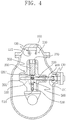
FIG. 4 is a second operating state diagram illustrating an earthing switch coupling state of the 3-way switch for the gas-insulated apparatus according to the present invention. - Hereinafter, preferred exemplary embodiments of the present invention will be described in detail with reference to the accompanying drawings.
- The terminologies used in the descriptions of the present invention are chosen based on the functions of corresponding elements of the present invention. Therefore, the terminologies used in the descriptions of the present invention are not committed to limit the technical elements of the present invention.
- As illustrated in
FIGS. 1A to 4 , a 3-way switch for a gas-insulated apparatus according to the present invention is designed so that a main lever which rotatably moves switches an operating part to linear motion to achieve neutrality, disconnection switching, and earthing switching, thereby reducing a driving radius and size of a device. - For this, the 3-way switch for the gas-insulated apparatus according to the present invention includes a
pressure container 100, asupport conductor 200, a disconnecting switch (DS) operatingpart 300, an earthing switch (ES) operatingpart 400, and amain lever 500. - First, the
pressure container 100 is fixedly installed in the gas-insulatedapparatus 10, and aspace part 110 is formed so that given pressure can be internally maintained. A first connectingpart 120 is provided in an upper portion of thespace part 110, and a second connectingpart 130 is provided in a side portion of thespace part 110 so that the second connectingpart 130 is perpendicular to the first connectingpart 120. - The first connecting
part 120 has a lower end on which afirst insertion groove 121 is formed so that one length-direction end of the DS operatingpart 300 to be described later can be inserted and connected, and the second connectingpart 130 has a side end on which asecond insertion groove 131 is formed so that one length-direction end of the ES operatingpart 400 to be described later can be inserted and connected. Here, the first connectingpart 120 and the second connectingpart 130 may be provided to project to the space part of thepressure container 100. - The
support conductor 200 is fixedly provided in thespace part 110. Thesupport conductor 200 has afirst guide hole 210 defined in a direction parallel to the direction of the first connectingpart 120 and asecond guide hole 220 defined in a direction parallel to the direction of the second connectingpart 130. - The DS operating
part 300 is vertically slidably coupled to thefirst guide hole 210 in a state in which the DS operatingpart 300 has been inserted within thefirst guide hole 210. The DS operatingpart 300 is opened and closed by the connection to or separation from the first connectingpart 120 through an insertion into or extrusion from an upper portion of thefirst guide hole 210. - The ES operating
part 400 is slidably coupled to thesecond guide hole 220 in a state in which the ES operatingpart 400 has been inserted into thesecond guide hole 220 such that the ES operatingpart 400 is perpendicular to the DS operating part. That is, the ES operatingpart 400 is opened and closed by the connection to or separation from the second connectingpart 130 through an insertion into or extrusion from a side portion of thesecond guide hole 220. - Also, the DS operating
part 300 has one end which is opposite to a direction of the first connectingpart 120 and rotatably connected to one end of a first connectinglever 510 through a first rotatable connectingroller 530. The other end of the first connectinglever 510 is rotatably connected to themain lever 500. - The ES operating
part 400 has one end which is opposite to a direction of the second connectingpart 130 and rotatably connected to one end of a second connectinglever 520 through a second rotatable connecting roller 530'. The other end of the second connectinglever 520 is rotatably connected to themain lever 500. - In addition, the
rotatable connecting rollers 530, 530' are provided in connection portions among the first connectinglever 510, the second connectinglever 520 and themain lever 500. It is preferable for a rotation angle of themain lever 500 to be 90°. - The
main lever 500 has one end which is rotatably coupled to thesupport conductor 200 and the other end which is eccentrically rotated and rotatably connected to the DS operatingpart 300 and the ES operatingpart 400, as described above and shown inFIG. 2 . - That is, the
main lever 500 is maintained in a neutral position as illustrated inFIG. 2 , or linearly slides the DS operatingpart 300 and the ES operatingpart 400 as inFIGS. 3 and4 . - On the other hand, the
main lever 500 is coupled to one end of aninsulation rod 600 which is connected to an external operating machine and transfers a turning force. Here, theinsulation rod 600 has one end of an axial direction coupled to themain lever 500 in a state in which the one end is rotatably coupled to thesupport conductor 200 and the other end rotatably coupled in a state in which the other end has passed through outside thepressure container 100. - Hereinafter, an operation sequence of the 3-way switch for the gas-insulated apparatus according to the present invention will be described with reference to
FIGS. 3 and4 . - First, an operation of the DS operating
part 300 as inFIG. 3 will be described. When theinsulation rod 600 connected to the outside in a neutral state is rotated at a given angle in a clockwise direction, themain lever 500 connected thereto is rotated and the first connectinglever 510 rotatably connected to themain lever 500 allows theconnecting roller 530 to be driven upwardly and linearly along afirst groove 201 formed in thesupport conductor 200. Thefirst groove 201 is formed in parallel with thefirst guide hole 210. - At this time, the first connecting
lever 510 upwardly pushes the DS operatingpart 300, so that switching to a DS coupling state is performed. A DS opening operation is performed in opposite order. - Next, an operation of the ES operating
part 400 as inFIG. 4 will be described. When theinsulation rod 600 connected to the outside in the neutral state is rotated at a given angle in a counterclockwise direction, themain lever 500 connected thereto is rotated and the second connectinglever 520 rotatably connected to themain lever 500 allows the second connecting roller 530' to be driven to the right side and linearly along a second groove 201' formed in thesupport conductor 200. The second groove 201' is formed in parallel with thesecond guide hole 220. - The
first groove 201 and the second groove 201' are formed in perpendicular with each other. - At this time, the second connecting
lever 520 pushes theES operating part 400 to one side, so that switching to an ES coupling state is performed. An ES opening operation is performed in opposite order. - Consequently, according to the present invention, the
main lever 500 which rotatably moves according to an external force switches an operating part to linear motion to achieve neutrality, disconnection switching, and earthing switching, thereby reducing a driving radius and size of a device. - Although the present invention for a 3-way switch for a gas-insulated apparatus has been described along with the accompanying drawings, this only illustrates preferred exemplary embodiments but not limits the scope of the present invention.
- Accordingly, it will be apparent for those skilled in the art that various modifications and imitations of dimensions, shapes, structures, etc. may be made without departing from the scope of the present invention.
- The present invention can be efficiently applied to a 3-way switch for a gas-insulated apparatus in which a main lever which rotatably moves according to an external force switches an operating part to linear motion to achieve neutrality, disconnection switching, and earthing switching, thereby reducing a driving radius and size of a device.
Claims (3)
- A 3-way switch for a gas-insulated apparatus, comprising:a pressure container (100) having a space part (110) therein, the pressure container (100) including a first connecting part (120) in an upper portion of the space part (110) and a second connecting part (130) in a side portion of the space part (110) such that the second connecting part (130) is perpendicular to the first connecting part (120);a support conductor (200) provided in the space part (110), the support conductor (200) having a first guide hole (210) and a second guide hole (220) formed perpendicular to the first guide hole (210);a disconnecting switch (DS) operating part (300) slidably disposed inside the first guide hole (210), the DS operating part (300) being connected to or separated from the first connecting part (120) by means of an insertion into or extrusion from the first connecting part (120);an earthing switch (ES) operating part (400) slidably disposed inside the second guide hole (220), the ES operating part (400) being connected to or separated from the second connecting part (130) through an insertion into or protrusion from the second connecting part (130);a first groove (201) linearly extended from the first guide hole (210), a first rotatable roller (530) slidably disposed in the first groove (201) and connected to the DS operating part (300) to slidably and linearly move therewith, and a first connecting lever (510), one end of which is rotatably connected to the first rotatable connecting roller (530);a second groove (201') linearly extended from the second guide hole (210), the second groove (201') being perpendicular to the first groove (201), a second rotatable roller (530') slidably disposed in the second groove (201') and connected to the ES operating part (400) to slidably and linearly move therewith, and a second connecting lever (520), one end of which is rotatably connected to the second rotatable connecting roller (530'); anda main lever (500), one end of which is rotatably coupled to the support conductor (200), and the other end of which is rotatably connected to both the other end of the first connecting lever (510) and the other end of the second connecting lever (520).
- The 3-way switch for the gas-insulated apparatus of claim 1, wherein a rotation angle of the main lever (500) is 90°.
- The 3-way switch for the gas-insulated apparatus of claim 1,
wherein the main lever (500) is coupled to one end of an insulation rod (600) which is connected to an external operating machine and transfers a turning force, and
wherein the insulation rod (600) has one end of an axial direction coupled to the main lever (500) in a state in which the one end is rotatably coupled to the support conductor (200) and the other end rotatably coupled in a state in which the other end has passed through outside the pressure container (100).
Applications Claiming Priority (2)
| Application Number | Priority Date | Filing Date | Title |
|---|---|---|---|
| KR1020110063221A KR101212783B1 (en) | 2011-06-28 | 2011-06-28 | 3-way switch of gas insulated switchgear |
| PCT/KR2012/001298 WO2013002472A1 (en) | 2011-06-28 | 2012-02-21 | 3-way switch for a gas-insulated apparatus |
Publications (3)
| Publication Number | Publication Date |
|---|---|
| EP2728603A1 EP2728603A1 (en) | 2014-05-07 |
| EP2728603A4 EP2728603A4 (en) | 2015-03-11 |
| EP2728603B1 true EP2728603B1 (en) | 2019-01-09 |
Family
ID=47424340
Family Applications (1)
| Application Number | Title | Priority Date | Filing Date |
|---|---|---|---|
| EP12803901.3A Active EP2728603B1 (en) | 2011-06-28 | 2012-02-21 | 3-way switch for a gas-insulated apparatus |
Country Status (4)
| Country | Link |
|---|---|
| US (1) | US9147540B2 (en) |
| EP (1) | EP2728603B1 (en) |
| KR (1) | KR101212783B1 (en) |
| WO (1) | WO2013002472A1 (en) |
Families Citing this family (8)
| Publication number | Priority date | Publication date | Assignee | Title |
|---|---|---|---|---|
| WO2012101758A1 (en) * | 2011-01-25 | 2012-08-02 | 三菱電機株式会社 | Switch |
| KR101605134B1 (en) * | 2014-07-01 | 2016-03-22 | 현대중공업 주식회사 | Disconnecting switch and earthing switch for gas insulated switchgear |
| CN105513879B (en) * | 2015-12-21 | 2018-11-27 | 平高集团有限公司 | A kind of transmission mechanism and the three-station using the transmission mechanism |
| WO2017141060A1 (en) * | 2016-02-18 | 2017-08-24 | Koncar - Elektricni Visokonaponski Aparati D.D. | Combined disconnecting-earthing switching module for a gas-insulated switchgear |
| EP3252793B1 (en) * | 2016-06-03 | 2021-01-27 | ABB Schweiz AG | Switching device with dual conductive housing |
| EP3336870B1 (en) * | 2016-12-14 | 2021-11-03 | General Electric Technology GmbH | A gis with a disconnector-earthing switch |
| KR101897736B1 (en) | 2017-01-06 | 2018-09-12 | 엘에스산전 주식회사 | 3 Way Disconnecting Switch and Earthing Switch for Gas Insulated Switch |
| CN114300295B (en) * | 2021-11-25 | 2025-04-08 | 河南平高电气股份有限公司 | Grounding switch for GIS |
Family Cites Families (11)
| Publication number | Priority date | Publication date | Assignee | Title |
|---|---|---|---|---|
| DE19519301A1 (en) * | 1995-05-26 | 1996-11-28 | Abb Management Ag | Disconnector for a metal-enclosed gas-insulated high-voltage switchgear |
| DE19615912A1 (en) * | 1996-04-22 | 1997-10-23 | Asea Brown Boveri | Disconnector |
| JPH10285729A (en) | 1997-04-03 | 1998-10-23 | Toshiba Corp | Disconnector with ground switch |
| FR2805406B1 (en) * | 2000-02-23 | 2002-08-23 | Alstom | THREE-POSITION ELECTRIC SWITCH WITH AN AXIALLY MOBILE SWITCHING ELEMENT |
| KR100347363B1 (en) | 2000-09-22 | 2002-08-07 | 엘지산전 주식회사 | Ds/es system of gas insulated switchgear |
| KR200321221Y1 (en) | 2003-05-06 | 2003-07-23 | 현대중공업 주식회사 | Development of the compact Disconnecting switch and Earthing switch for the Gas lnsulated Switchgear |
| KR20050098360A (en) * | 2004-04-06 | 2005-10-12 | 주식회사 효성 | Disconnecting/earthing switch for gas-insulated switchgear |
| JP2007087836A (en) * | 2005-09-26 | 2007-04-05 | Hitachi Ltd | Gas circuit breaker for electric power |
| FR2937176B1 (en) | 2008-10-14 | 2010-12-03 | Areva T & D Ag | ELECTRIC SWITCHING APPARATUS FOR HIGH OR MEDIUM VOLTAGE OF TWO SWITCHES COMPRISING DRIVING MEANS COMMON TO THE MOBILE CONTACTS OF THE SWITCHES. |
| FR2937175B1 (en) * | 2008-10-14 | 2010-12-03 | Areva T & D Sa | ELECTRICAL SWITCHING APPARATUS HAVING TWO SWITCHES, SUCH AS A BAR BREAKER AND A GROUND DISCONNECT AND COMPRISING COMMON TRAINING MEANS OF THE MOBILE SWITCH CONTACTS. |
| JP5471925B2 (en) * | 2010-07-16 | 2014-04-16 | 株式会社日立製作所 | Disconnector with earthing switch |
-
2011
- 2011-06-28 KR KR1020110063221A patent/KR101212783B1/en active Active
-
2012
- 2012-02-21 US US14/126,532 patent/US9147540B2/en active Active
- 2012-02-21 EP EP12803901.3A patent/EP2728603B1/en active Active
- 2012-02-21 WO PCT/KR2012/001298 patent/WO2013002472A1/en not_active Ceased
Non-Patent Citations (1)
| Title |
|---|
| None * |
Also Published As
| Publication number | Publication date |
|---|---|
| US9147540B2 (en) | 2015-09-29 |
| EP2728603A4 (en) | 2015-03-11 |
| EP2728603A1 (en) | 2014-05-07 |
| US20140116859A1 (en) | 2014-05-01 |
| WO2013002472A1 (en) | 2013-01-03 |
| KR101212783B1 (en) | 2012-12-18 |
Similar Documents
| Publication | Publication Date | Title |
|---|---|---|
| US9147540B2 (en) | 3-way switch for a gas-insulated apparatus | |
| US20100089875A1 (en) | High and medium voltage switch apparatus with two interrupters, having common means for actuating the movable contacts of the interrupters | |
| US10121625B2 (en) | 3-way disconnector and earth switch for gas insulated switchgear | |
| CN103166143B (en) | A kind of solid insulation ring main unit | |
| CN1783609B (en) | Gas Insulated Switchgear | |
| KR100990477B1 (en) | Gas insulated switchgear | |
| EP3232522B1 (en) | Switchgear | |
| KR101238912B1 (en) | Sector gear and gas-insulated switchgear having the same | |
| CN219476528U (en) | Interlocking mechanism of 24KV solid insulation switch cabinet | |
| RU2516446C2 (en) | Electrical switch having two breakers, such as bus disconnector and earthing disconnector, and having common actuator for movable contacts of breakers | |
| CN203135294U (en) | Solid insulation ring main unit | |
| CN102959668B (en) | Compact ground isolator | |
| KR200321221Y1 (en) | Development of the compact Disconnecting switch and Earthing switch for the Gas lnsulated Switchgear | |
| JPH11162303A (en) | Switchgear | |
| KR101390499B1 (en) | Disconnecting switch and earthing switch of gas insulated switchgear | |
| KR100397567B1 (en) | Gas insulated switchgear | |
| KR102171601B1 (en) | Electrode driving apparatus for gas insulated switchgear | |
| KR101060827B1 (en) | Gas Insulated Switchgear | |
| KR200486467Y1 (en) | Gas insulated high voltage switchgear | |
| KR101072544B1 (en) | Gas Insulated Switchgear | |
| JP7499703B2 (en) | High Voltage Circuit Breaker | |
| KR20120128416A (en) | Gas insulated switchgear | |
| JP2007179934A (en) | Switchgear | |
| KR20120127851A (en) | Gas-insulated switchgear | |
| CN205487904U (en) | Be used for alternate driven transmission insulator and isolator and GIS |
Legal Events
| Date | Code | Title | Description |
|---|---|---|---|
| PUAI | Public reference made under article 153(3) epc to a published international application that has entered the european phase |
Free format text: ORIGINAL CODE: 0009012 |
|
| 17P | Request for examination filed |
Effective date: 20131220 |
|
| AK | Designated contracting states |
Kind code of ref document: A1 Designated state(s): AL AT BE BG CH CY CZ DE DK EE ES FI FR GB GR HR HU IE IS IT LI LT LU LV MC MK MT NL NO PL PT RO RS SE SI SK SM TR |
|
| DAX | Request for extension of the european patent (deleted) | ||
| A4 | Supplementary search report drawn up and despatched |
Effective date: 20150206 |
|
| RIC1 | Information provided on ipc code assigned before grant |
Ipc: H01H 33/42 20060101ALI20150202BHEP Ipc: H01H 31/00 20060101AFI20150202BHEP Ipc: H01H 31/32 20060101ALI20150202BHEP Ipc: H01H 33/64 20060101ALN20150202BHEP Ipc: H01H 1/38 20060101ALN20150202BHEP |
|
| STAA | Information on the status of an ep patent application or granted ep patent |
Free format text: STATUS: EXAMINATION IS IN PROGRESS |
|
| 17Q | First examination report despatched |
Effective date: 20161205 |
|
| RAP1 | Party data changed (applicant data changed or rights of an application transferred) |
Owner name: HYUNDAI ELECTRIC & ENERGY SYSTEMS CO., LTD. |
|
| REG | Reference to a national code |
Ref country code: DE Ref legal event code: R079 Ref document number: 602012055787 Country of ref document: DE Free format text: PREVIOUS MAIN CLASS: H01H0033660000 Ipc: H01H0031000000 |
|
| GRAP | Despatch of communication of intention to grant a patent |
Free format text: ORIGINAL CODE: EPIDOSNIGR1 |
|
| STAA | Information on the status of an ep patent application or granted ep patent |
Free format text: STATUS: GRANT OF PATENT IS INTENDED |
|
| RIC1 | Information provided on ipc code assigned before grant |
Ipc: H01H 31/32 20060101ALI20180706BHEP Ipc: H01H 33/64 20060101ALN20180706BHEP Ipc: H01H 33/42 20060101ALI20180706BHEP Ipc: H01H 31/00 20060101AFI20180706BHEP Ipc: H01H 1/38 20060101ALN20180706BHEP |
|
| INTG | Intention to grant announced |
Effective date: 20180726 |
|
| GRAS | Grant fee paid |
Free format text: ORIGINAL CODE: EPIDOSNIGR3 |
|
| GRAA | (expected) grant |
Free format text: ORIGINAL CODE: 0009210 |
|
| STAA | Information on the status of an ep patent application or granted ep patent |
Free format text: STATUS: THE PATENT HAS BEEN GRANTED |
|
| AK | Designated contracting states |
Kind code of ref document: B1 Designated state(s): AL AT BE BG CH CY CZ DE DK EE ES FI FR GB GR HR HU IE IS IT LI LT LU LV MC MK MT NL NO PL PT RO RS SE SI SK SM TR |
|
| REG | Reference to a national code |
Ref country code: GB Ref legal event code: FG4D |
|
| REG | Reference to a national code |
Ref country code: CH Ref legal event code: EP Ref country code: AT Ref legal event code: REF Ref document number: 1088353 Country of ref document: AT Kind code of ref document: T Effective date: 20190115 |
|
| REG | Reference to a national code |
Ref country code: DE Ref legal event code: R096 Ref document number: 602012055787 Country of ref document: DE |
|
| REG | Reference to a national code |
Ref country code: IE Ref legal event code: FG4D |
|
| REG | Reference to a national code |
Ref country code: NL Ref legal event code: MP Effective date: 20190109 |
|
| REG | Reference to a national code |
Ref country code: LT Ref legal event code: MG4D |
|
| PG25 | Lapsed in a contracting state [announced via postgrant information from national office to epo] |
Ref country code: NL Free format text: LAPSE BECAUSE OF FAILURE TO SUBMIT A TRANSLATION OF THE DESCRIPTION OR TO PAY THE FEE WITHIN THE PRESCRIBED TIME-LIMIT Effective date: 20190109 |
|
| REG | Reference to a national code |
Ref country code: AT Ref legal event code: MK05 Ref document number: 1088353 Country of ref document: AT Kind code of ref document: T Effective date: 20190109 |
|
| PG25 | Lapsed in a contracting state [announced via postgrant information from national office to epo] |
Ref country code: PT Free format text: LAPSE BECAUSE OF FAILURE TO SUBMIT A TRANSLATION OF THE DESCRIPTION OR TO PAY THE FEE WITHIN THE PRESCRIBED TIME-LIMIT Effective date: 20190509 Ref country code: LT Free format text: LAPSE BECAUSE OF FAILURE TO SUBMIT A TRANSLATION OF THE DESCRIPTION OR TO PAY THE FEE WITHIN THE PRESCRIBED TIME-LIMIT Effective date: 20190109 Ref country code: FI Free format text: LAPSE BECAUSE OF FAILURE TO SUBMIT A TRANSLATION OF THE DESCRIPTION OR TO PAY THE FEE WITHIN THE PRESCRIBED TIME-LIMIT Effective date: 20190109 Ref country code: SE Free format text: LAPSE BECAUSE OF FAILURE TO SUBMIT A TRANSLATION OF THE DESCRIPTION OR TO PAY THE FEE WITHIN THE PRESCRIBED TIME-LIMIT Effective date: 20190109 Ref country code: ES Free format text: LAPSE BECAUSE OF FAILURE TO SUBMIT A TRANSLATION OF THE DESCRIPTION OR TO PAY THE FEE WITHIN THE PRESCRIBED TIME-LIMIT Effective date: 20190109 Ref country code: NO Free format text: LAPSE BECAUSE OF FAILURE TO SUBMIT A TRANSLATION OF THE DESCRIPTION OR TO PAY THE FEE WITHIN THE PRESCRIBED TIME-LIMIT Effective date: 20190409 Ref country code: PL Free format text: LAPSE BECAUSE OF FAILURE TO SUBMIT A TRANSLATION OF THE DESCRIPTION OR TO PAY THE FEE WITHIN THE PRESCRIBED TIME-LIMIT Effective date: 20190109 |
|
| PG25 | Lapsed in a contracting state [announced via postgrant information from national office to epo] |
Ref country code: RS Free format text: LAPSE BECAUSE OF FAILURE TO SUBMIT A TRANSLATION OF THE DESCRIPTION OR TO PAY THE FEE WITHIN THE PRESCRIBED TIME-LIMIT Effective date: 20190109 Ref country code: LV Free format text: LAPSE BECAUSE OF FAILURE TO SUBMIT A TRANSLATION OF THE DESCRIPTION OR TO PAY THE FEE WITHIN THE PRESCRIBED TIME-LIMIT Effective date: 20190109 Ref country code: IS Free format text: LAPSE BECAUSE OF FAILURE TO SUBMIT A TRANSLATION OF THE DESCRIPTION OR TO PAY THE FEE WITHIN THE PRESCRIBED TIME-LIMIT Effective date: 20190509 Ref country code: HR Free format text: LAPSE BECAUSE OF FAILURE TO SUBMIT A TRANSLATION OF THE DESCRIPTION OR TO PAY THE FEE WITHIN THE PRESCRIBED TIME-LIMIT Effective date: 20190109 Ref country code: GR Free format text: LAPSE BECAUSE OF FAILURE TO SUBMIT A TRANSLATION OF THE DESCRIPTION OR TO PAY THE FEE WITHIN THE PRESCRIBED TIME-LIMIT Effective date: 20190410 Ref country code: BG Free format text: LAPSE BECAUSE OF FAILURE TO SUBMIT A TRANSLATION OF THE DESCRIPTION OR TO PAY THE FEE WITHIN THE PRESCRIBED TIME-LIMIT Effective date: 20190409 |
|
| REG | Reference to a national code |
Ref country code: CH Ref legal event code: PL |
|
| REG | Reference to a national code |
Ref country code: DE Ref legal event code: R097 Ref document number: 602012055787 Country of ref document: DE |
|
| PG25 | Lapsed in a contracting state [announced via postgrant information from national office to epo] |
Ref country code: LU Free format text: LAPSE BECAUSE OF NON-PAYMENT OF DUE FEES Effective date: 20190221 Ref country code: SK Free format text: LAPSE BECAUSE OF FAILURE TO SUBMIT A TRANSLATION OF THE DESCRIPTION OR TO PAY THE FEE WITHIN THE PRESCRIBED TIME-LIMIT Effective date: 20190109 Ref country code: IT Free format text: LAPSE BECAUSE OF FAILURE TO SUBMIT A TRANSLATION OF THE DESCRIPTION OR TO PAY THE FEE WITHIN THE PRESCRIBED TIME-LIMIT Effective date: 20190109 Ref country code: EE Free format text: LAPSE BECAUSE OF FAILURE TO SUBMIT A TRANSLATION OF THE DESCRIPTION OR TO PAY THE FEE WITHIN THE PRESCRIBED TIME-LIMIT Effective date: 20190109 Ref country code: RO Free format text: LAPSE BECAUSE OF FAILURE TO SUBMIT A TRANSLATION OF THE DESCRIPTION OR TO PAY THE FEE WITHIN THE PRESCRIBED TIME-LIMIT Effective date: 20190109 Ref country code: CZ Free format text: LAPSE BECAUSE OF FAILURE TO SUBMIT A TRANSLATION OF THE DESCRIPTION OR TO PAY THE FEE WITHIN THE PRESCRIBED TIME-LIMIT Effective date: 20190109 Ref country code: MC Free format text: LAPSE BECAUSE OF FAILURE TO SUBMIT A TRANSLATION OF THE DESCRIPTION OR TO PAY THE FEE WITHIN THE PRESCRIBED TIME-LIMIT Effective date: 20190109 Ref country code: AT Free format text: LAPSE BECAUSE OF FAILURE TO SUBMIT A TRANSLATION OF THE DESCRIPTION OR TO PAY THE FEE WITHIN THE PRESCRIBED TIME-LIMIT Effective date: 20190109 Ref country code: DK Free format text: LAPSE BECAUSE OF FAILURE TO SUBMIT A TRANSLATION OF THE DESCRIPTION OR TO PAY THE FEE WITHIN THE PRESCRIBED TIME-LIMIT Effective date: 20190109 Ref country code: AL Free format text: LAPSE BECAUSE OF FAILURE TO SUBMIT A TRANSLATION OF THE DESCRIPTION OR TO PAY THE FEE WITHIN THE PRESCRIBED TIME-LIMIT Effective date: 20190109 |
|
| PLBE | No opposition filed within time limit |
Free format text: ORIGINAL CODE: 0009261 |
|
| STAA | Information on the status of an ep patent application or granted ep patent |
Free format text: STATUS: NO OPPOSITION FILED WITHIN TIME LIMIT |
|
| REG | Reference to a national code |
Ref country code: BE Ref legal event code: MM Effective date: 20190228 |
|
| PG25 | Lapsed in a contracting state [announced via postgrant information from national office to epo] |
Ref country code: SM Free format text: LAPSE BECAUSE OF FAILURE TO SUBMIT A TRANSLATION OF THE DESCRIPTION OR TO PAY THE FEE WITHIN THE PRESCRIBED TIME-LIMIT Effective date: 20190109 |
|
| 26N | No opposition filed |
Effective date: 20191010 |
|
| GBPC | Gb: european patent ceased through non-payment of renewal fee |
Effective date: 20190409 |
|
| PG25 | Lapsed in a contracting state [announced via postgrant information from national office to epo] |
Ref country code: LI Free format text: LAPSE BECAUSE OF NON-PAYMENT OF DUE FEES Effective date: 20190228 Ref country code: CH Free format text: LAPSE BECAUSE OF NON-PAYMENT OF DUE FEES Effective date: 20190228 |
|
| PG25 | Lapsed in a contracting state [announced via postgrant information from national office to epo] |
Ref country code: GB Free format text: LAPSE BECAUSE OF NON-PAYMENT OF DUE FEES Effective date: 20190409 Ref country code: IE Free format text: LAPSE BECAUSE OF NON-PAYMENT OF DUE FEES Effective date: 20190221 |
|
| PG25 | Lapsed in a contracting state [announced via postgrant information from national office to epo] |
Ref country code: SI Free format text: LAPSE BECAUSE OF FAILURE TO SUBMIT A TRANSLATION OF THE DESCRIPTION OR TO PAY THE FEE WITHIN THE PRESCRIBED TIME-LIMIT Effective date: 20190109 Ref country code: BE Free format text: LAPSE BECAUSE OF NON-PAYMENT OF DUE FEES Effective date: 20190228 Ref country code: FR Free format text: LAPSE BECAUSE OF NON-PAYMENT OF DUE FEES Effective date: 20190309 |
|
| PG25 | Lapsed in a contracting state [announced via postgrant information from national office to epo] |
Ref country code: TR Free format text: LAPSE BECAUSE OF FAILURE TO SUBMIT A TRANSLATION OF THE DESCRIPTION OR TO PAY THE FEE WITHIN THE PRESCRIBED TIME-LIMIT Effective date: 20190109 |
|
| PG25 | Lapsed in a contracting state [announced via postgrant information from national office to epo] |
Ref country code: MT Free format text: LAPSE BECAUSE OF NON-PAYMENT OF DUE FEES Effective date: 20190221 |
|
| PG25 | Lapsed in a contracting state [announced via postgrant information from national office to epo] |
Ref country code: CY Free format text: LAPSE BECAUSE OF FAILURE TO SUBMIT A TRANSLATION OF THE DESCRIPTION OR TO PAY THE FEE WITHIN THE PRESCRIBED TIME-LIMIT Effective date: 20190109 |
|
| PG25 | Lapsed in a contracting state [announced via postgrant information from national office to epo] |
Ref country code: HU Free format text: LAPSE BECAUSE OF FAILURE TO SUBMIT A TRANSLATION OF THE DESCRIPTION OR TO PAY THE FEE WITHIN THE PRESCRIBED TIME-LIMIT; INVALID AB INITIO Effective date: 20120221 |
|
| PG25 | Lapsed in a contracting state [announced via postgrant information from national office to epo] |
Ref country code: MK Free format text: LAPSE BECAUSE OF FAILURE TO SUBMIT A TRANSLATION OF THE DESCRIPTION OR TO PAY THE FEE WITHIN THE PRESCRIBED TIME-LIMIT Effective date: 20190109 |
|
| PGFP | Annual fee paid to national office [announced via postgrant information from national office to epo] |
Ref country code: DE Payment date: 20260105 Year of fee payment: 15 |