EP2728331A1 - Methods and Systems for Monitoring Health of Blades - Google Patents
Methods and Systems for Monitoring Health of Blades Download PDFInfo
- Publication number
- EP2728331A1 EP2728331A1 EP13189169.9A EP13189169A EP2728331A1 EP 2728331 A1 EP2728331 A1 EP 2728331A1 EP 13189169 A EP13189169 A EP 13189169A EP 2728331 A1 EP2728331 A1 EP 2728331A1
- Authority
- EP
- European Patent Office
- Prior art keywords
- blades
- preliminary
- clearance
- blade passing
- voltages
- Prior art date
- Legal status (The legal status is an assumption and is not a legal conclusion. Google has not performed a legal analysis and makes no representation as to the accuracy of the status listed.)
- Granted
Links
Images


Classifications
-
- G—PHYSICS
- G01—MEASURING; TESTING
- G01M—TESTING STATIC OR DYNAMIC BALANCE OF MACHINES OR STRUCTURES; TESTING OF STRUCTURES OR APPARATUS, NOT OTHERWISE PROVIDED FOR
- G01M5/00—Investigating the elasticity of structures, e.g. deflection of bridges or air-craft wings
- G01M5/0083—Investigating the elasticity of structures, e.g. deflection of bridges or air-craft wings by measuring variation of impedance, e.g. resistance, capacitance, induction
-
- G—PHYSICS
- G01—MEASURING; TESTING
- G01B—MEASURING LENGTH, THICKNESS OR SIMILAR LINEAR DIMENSIONS; MEASURING ANGLES; MEASURING AREAS; MEASURING IRREGULARITIES OF SURFACES OR CONTOURS
- G01B7/00—Measuring arrangements characterised by the use of electric or magnetic techniques
- G01B7/14—Measuring arrangements characterised by the use of electric or magnetic techniques for measuring distance or clearance between spaced objects or spaced apertures
-
- G—PHYSICS
- G01—MEASURING; TESTING
- G01M—TESTING STATIC OR DYNAMIC BALANCE OF MACHINES OR STRUCTURES; TESTING OF STRUCTURES OR APPARATUS, NOT OTHERWISE PROVIDED FOR
- G01M5/00—Investigating the elasticity of structures, e.g. deflection of bridges or air-craft wings
- G01M5/0091—Investigating the elasticity of structures, e.g. deflection of bridges or air-craft wings by using electromagnetic excitation or detection
Definitions
- Embodiments of the invention relate generally to the field of prognostics of blades or airfoils, and more specifically to methods and systems for determination of health of blades.
- Rotor blades or airfoils are used in several devices, for example, axial compressors, turbines, engines, turbomachines, or the like.
- An axial compressor has a series of stages with each stage comprising a row of rotor blades or airfoils followed by a row of static blades or static airfoils. Accordingly, each stage comprises a pair of rotor blades or airfoils and static airfoils.
- the rotor blades increase the kinetic energy of a fluid that enters the axial compressor through an inlet.
- the static blades generally convert the increased kinetic energy of the fluid into static pressure through diffusion. Accordingly, the rotor blades and static blades play an important role to increase the pressure of the fluid.
- Axial compressors may be used in a number of devices, such as, land based gas turbines, jet engines, high speed ship engines, small scale power stations, or the like.
- the axial compressors may be used in other applications, such as, large volume air separation plants, blast furnace air, fluid catalytic cracking air, propane dehydrogenation, or the like.
- the blades or airfoils operate for long hours under extreme and varied operating conditions, such as, high speed, fluid load, and temperature that affect the health of the airfoils.
- extreme and varied operating conditions such as, high speed, fluid load, and temperature that affect the health of the airfoils.
- certain other factors lead to fatigue and stress on the airfoils.
- the factors may include centrifugal forces, fluid forces, thermal loads during transient events, load due to non-synchronous vibration, such as, rotating stall, and the cyclic load due to synchronous resonant vibration. Prolonged effects of the factors lead to defects, such as, tip loss, or deflection in the airfoils.
- a system includes a processing subsystem that determines preliminary voltages corresponding to a plurality of blades based upon blade passing signals (BPS), and generates a plurality of clearance values by normalizing the preliminary voltages for effects of one or more operational parameters, wherein the plurality of clearance values are representative of clearance of the plurality of blades.
- BPS blade passing signals
- a method includes the steps of determining preliminary voltages corresponding to a plurality of blades based upon blade passing signals (BPS), and generating a plurality of clearance values by normalizing the preliminary voltages for effects of one or more operational parameters, wherein the plurality of clearance values are representative of clearance of the plurality of blades.
- BPS blade passing signals
- the term "clearance” may refer to a distance or spacing between two objects.
- compressors include blades that are covered by a casing.
- the radial distance between the blades and the casing or sensors located on the casing is generally referred to as clearance of the blades.
- the term “clearance” may also be used to refer to radial distances between the tips of the blades and the internal surface of the casing. Clearance may be used for determination of the health of the blades, and prevention of the compressors from damage. For example, an increase in the clearance of a blade A may be due to a bend, a tip loss, or a crack in the blade A. Similarly, a reduction in the clearance of the blade A may be due to reseating of the blade A.
- embodiments of the present systems and methods estimate and monitor clearance between two objects, such as, clearance between a turbine blade and a casing, in real-time. Furthermore, embodiments of the present systems and techniques monitor the health of the blades in real-time.
- Fig. 1 is a diagrammatic illustration of a system 10 for determination of the health of a plurality of blades 12.
- the system 10 includes a device 14 and a health monitoring sub-system 16.
- the device 14, for example, may be a turbine engine, a compressor, a turbine, or the like.
- the system 10 is shown to include a portion of the device 14.
- the device 14 is a turbine engine, and the portion of the device 14 is a compressor.
- the health monitoring sub-system 16 is in an operational communication with the compressor 14.
- the health monitoring sub-system 16 may be a processing subsystem, a computing device, or the like.
- the health monitoring sub-system 16 may be located in vicinity of the device 14.
- the health monitoring sub-system 16 may be located in a cloud.
- the health monitoring sub-system 16 may be located at a remote location with respect to the location of the device 14.
- the compressor 14 includes the blades 12 that are covered by a casing 18.
- the system 10 includes a plurality of sensors 20, 22 that are operationally coupled to the health monitoring sub-system 16.
- the sensors 20, 22 are electromagnetic sensors or eddy current sensors.
- the sensors 20, 22, for example may be a magnetic sensor, a capacitive sensor, an eddy current sensor, or the like.
- the sensors 20, 22 generate blade passing signals (BPS) 24, 26 when a blade in the blades 12 passes through under the sensors 20, 22.
- BPS blade passing signals
- a blade that passes through under the sensors 20, 22, for example, may be identified by dividing a total time period for a revolution of a rotor 25 of the blades 12 by a total number of blades 12 in the rotor 25.
- each of the sensors 20, 22 may include a magnet core surrounded by a coil.
- the sensor 20 includes a magnet core M (now shown) that is surrounded by a coil C (not shown), then the magnet core M is ensconced within the coil C.
- the magnet core M produces a magnetic flux field.
- the blade in the blades 12 changes the permeability of a distance/spacing between the blade and the casing 18.
- a voltage is induced in the coil C in the sensor 20.
- the sensor 20 generates the signals 24 that are representative of the induced voltage in the coil C. Accordingly, in one embodiment, when the sensors 20, 22 are magnetic sensors, the sensors 20, 22 generate BPS signals 24, 26 that are representative of induced voltages in respective coils of the sensors 20, 22.
- An exemplary BPS is described in detail with reference to Fig. 2 .
- the system 10 further includes an onsite monitoring device 28.
- the onsite monitoring device 28 is in an operational communication with the device 14 and the health monitoring sub-system 16.
- the onsite monitoring device 28 receives data from the device 14, and generates operational parameters 30 based upon the received data.
- the operational parameters 30, for example, include a speed of the device 14, a temperature of the device 14 at the time of generation of the BPS 24, 26, an inlet guide vane parameter, or the like.
- the onsite monitoring device 28 transmits the operational parameters to the health monitoring sub-system 16.
- the sensors 20, 22 transmit the BPS 24, 26 to the health monitoring sub-system 16.
- the health monitoring sub-system 16 receives the BPS 24, 26 from the sensors 20, 22.
- the health monitoring sub-system 16 determines and monitors the health of the blades 12 based upon the BPS 24, 26 and one or more of the operational parameters 30, in real-time.
- the health monitoring sub-system 16 determines clearance of the blades 12 based upon the BPS 24, 26 and one or more of the operational parameters 30.
- the health monitoring sub-system 16 determines preliminary voltages corresponding to the blades 12 based upon the BPS 24, 26. Furthermore, the health monitoring sub-system 16 normalizes the preliminary voltages for effects of one or more of the operational parameters 30 to generate a plurality of clearance values. In one embodiment, the health monitoring sub-system 16 determines and monitors the clearance of the blades 12 in real-time. It is noted that the clearance values are representative of the clearance of the blades 12. The determination of the clearance and the health of the blades 12 are explained in greater detail with reference to Fig. 3 .
- the health monitoring subsystem 16 generates one or more alarms to indicate defects in the blades 12 or the sensors 20, 22.
- the health monitoring sub-system 16 generates the alarms based upon the preliminary voltages or the clearance values. Generation of the alarms is explained in detail with reference to Fig. 3 .
- the system 10 includes a display device 32 that is in an operational communication with the health monitoring system 16.
- the display device 32 displays the BPS 24, 26, the clearance values, one or more intermediate processes or values, the alarms, or the like.
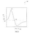
- Fig. 2 is a graphical representation of an experimental BPS 200, in accordance with one embodiment of the present techniques.
- the BPS signal 200 may be one of the BPS 24, 26 generated by the sensors 20, 22, respectively.
- the BPS 200 will be explained assuming that the BPS 200 corresponds to a blade A, and is generated by the sensor 20.
- the sensor 20 is a magnetic sensor.
- the BPS 200 shown in Fig. 2 is a graphical representation of a voltage induced in respective coil of the sensor 20 (see Fig. 1 ).
- the BPS 200 will be explained assuming that the device 14 that includes the sensor 20 is operating in ideal conditions. In the ideal conditions, noise induced in the BPS 200 is substantially minimal.
- Y-axis 202 represents voltage generated by the sensor 20, and X-axis 204 represents time of generation of the voltage.
- X-axis 204 represents time of generation of the voltage.
- the leading edge of the blade A starts disrupting the magnetic flux of the sensor 20, and the disruption increases with time leading to an increase in the voltage, and finally reaches a maximum value as shown by reference numeral 208.
- the sensor 20 generates the maximum voltage 208 when the leading edge of the blade A reaches the center of the sensor tip 20.
- the voltage starts falling from the maximum value 208.
- the trailing edge of the blade A reaches the tip of the sensor 20, the voltage reaches a minimum value as shown by reference numeral 210.
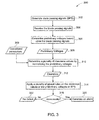
- FIG. 3 is a flow chart 300 illustrating an exemplary method for determination of clearance of blades, in accordance with aspects of the present technique.
- blade passing signals corresponding to a plurality of blades are generated.
- the blade passing signals may correspond to the blades 12 (see Fig. 1 ), and may be generated by the sensors 20, 22 (see Fig. 1 ).
- the blade passing signals may be the blade passing signals (BPS) 24, 26 (see Fig. 1 ).
- the BPS are received.
- the BPS for example, may be received by the health monitoring sub-system 16 (see Fig. 1 ).
- preliminary voltages 308 corresponding to the blades may be determined based upon the BPS.
- the preliminary voltages 308 may be determined based upon a subset of the BPS.
- the preliminary voltages may be determined based upon a subset of the BPS that is generated during steady state of a device that includes the blades. Determination of the preliminary voltages 308 based upon the BPS is explained in detail with reference to Fig. 4 .
- a plurality of preset rules are applied to the clearance values 312, the preliminary voltages 308, and/or the BPS.
- the preset rules may include comparison of the clearance values 312 or the preliminary voltages 308 to a plurality of thresholds.
- the preset rules are applied to the blade passing signals to determine existence of defects in sensors, such as, the sensors 24, 26, or the blades 12. Certain examples of the preset rules are explained with reference to Fig. 7(a), 7(b) and 7(c) .
- a determination is made whether the blades, such as, the blades 12, or sensors, such as, the sensors 20, 22 have a defect.
- the determination is made based upon the application of the preset rules to the preliminary voltages 308, the clearance values 312 and/or the BPS.
- the control is transferred to step 320.
- an alarm is generated to indicate the one or more defects in the one or more of the blades.
- Av step 322 when it is determined that one or more defects do not exist in the blades or the sensors, then the control is transferred to step 322. At step 322, it is declared that defects exist in the blades or the sensors.
- Fig. 4 is a flowchart 400 illustrating an exemplary method for determination of preliminary voltages, in accordance with aspects of the present techniques. Particularly, Fig. 4 explains step 306 in Fig. 3 in greater detail.
- the preliminary voltages may be the preliminary voltages 308 (see Fig. 3 ).
- Fig. 4 explains determination of a single preliminary voltage 410 corresponding to a blade passing signal (BPS) 402.
- BPS 402 for example, may be one of the BPS 24, 26 (see Fig. 1 ) or the BPS 200 (see Fig. 2 ).
- an ascending index value and a descending index value corresponding to the BPS 402 is determined.
- the ascending index value and the descending index value are determined based upon the BPS 402 and an index value threshold.
- the index value threshold refers to a constant value corresponding to a device that is determined based upon the preliminary voltage of blades at rotating at turning gear speed.
- the determination of the ascending index value and the descending index value is explained in detail with reference to Fig. 5 .
- an average value of the ascending index value and the descending index value is determined.
- the average value is thereafter mapped to a corresponding voltage value using the blade passing signal 402 at step 408.
- the corresponding voltage value is declared as the preliminary voltage 410.
- the determination of the ascending index value, the descending index value, the average value and the preliminary voltage is explained with reference to Fig. 5 .
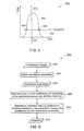
- a graphical representation 500 of a blade passing signal 502 is shown to describe determination of an ascending index value and a descending index value corresponding to the blade passing signal 502.
- the BPS 502 may be one of the BPS 24, 26, 200, 402 (see Fig. 1 , Fig. 2 and Fig. 4 ).
- Fig. 5 explains step 404 in Fig. 4 in greater detail.
- reference numeral 504 is representative of an index value threshold.
- the index value threshold cuts through the blade passing signal 502 at two points 506, 508.
- a plurality of points located around the point 506 are interpolated to determine the ascending index value. Furthermore, a plurality of points located around the point 508 are interpolated to determine the descending index value. Furthermore, reference numeral 510 represents an average value of the ascending index value and the descending index value. The average 510 is thereafter mapped to a corresponding voltage 512 to determine the preliminary voltage 512.
- Fig. 6 is a flowchart 600 that illustrates an exemplary method for determination of a clearance value 612 corresponding to a blade, in accordance with aspects of the present techniques. Particularly, Fig. 6 explains step 310 in Fig. 3 in greater detail.
- the clearance value 612 may be one of the clearance values 312 (see Fig. 3 ).
- Reference numeral 602 is representative of a preliminary voltage.
- the preliminary voltage 602 for example, may be one of the preliminary voltages 308 (see Fig. 3 ).
- one or more operational parameters 606 may be selected. In one embodiment, the operational parameters 606 may be selected by a user.
- the operational parameters 606 may be selected once by a user, and thereafter the operational parameters 606 may be used by default.
- the operational parameters 606, for example, may be a subset of the operational parameters 309 (see Fig. 3 ).
- one or more coefficients corresponding to the operational parameters and the clearance 612 may be determined.
- the one or more coefficients may be determined by varying experimental clearance values with respect to each of the operational parameters 606 while holding the rest of the operational parameters 606 constant.
- the clearance value 612 corresponding to the preliminary voltage 602 may be generated.
- the clearance value 612 may be generated by solving an empirical formula using the one or more coefficients, the preliminary voltage 602 and the operational parameters 606.
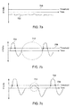
- Fig. 7a, Fig. 7b and Fig. 7c are exemplary graphical representations of blade passing signals 702, 704, 706 that are shown for describing certain embodiments of preset rules. Particularly, Fig. 7a, Fig. 7b and Fig. 7c describe the preset rules referred to in step 314 in Fig. 3 , in accordance with one embodiment of the present techniques.
- the preset rule may include a condition, that when a blade passing signal, a preliminary voltage or a clearance value is less than a predetermined threshold and is less than zero, or the blade passing signal has a flat lined appearance, then a defect exists in a sensor. For example, as shown in Fig.
- the blade passing signal 702 has corresponding preliminary voltages that are less than a threshold 708 and are less than zero volts. Furthermore, as shown in Fig. 7(a) , the BPS 702 has a flat lined appearance. Therefore, it may be declared that a defect exists in a sensor that generated the BPS 702.
- This rule includes a condition that when a blade passing signal corresponding to a blade is cropped for a minimum duration, then there may be a tip loss of the blade. As shown in Fig. 7(b) , the blade passing signal 704 corresponding to the blade is cropped for a specific duration as shown by the reference numeral 712. Accordingly, it may be deduced that the blade may have a tip loss defect.
- Still another exemplary preset rule may include a condition that when a plurality of preliminary voltages are less than a threshold for a predetermnined duration, then there is a defect in a blade. As shown in Fig. 7 ⁇ by reference numeral 714, a plurality of preliminary voltages are less than the threshold 708 for a specific period. Therefore, it may be deduced that there is a defect in the blade. It is noted that the preset rules explained with reference to Fig. 7(a), Fig. 7(b) and Fig. 7(c) are for exemplary purposes. It is noted that many other embodiments of the preset rules may exist.
Landscapes
- Physics & Mathematics (AREA)
- General Physics & Mathematics (AREA)
- Engineering & Computer Science (AREA)
- Aviation & Aerospace Engineering (AREA)
- Electromagnetism (AREA)
- Structures Of Non-Positive Displacement Pumps (AREA)
- Measurement Of Length, Angles, Or The Like Using Electric Or Magnetic Means (AREA)
- Testing Of Devices, Machine Parts, Or Other Structures Thereof (AREA)
- Testing Of Engines (AREA)
Abstract
Description
- Embodiments of the invention relate generally to the field of prognostics of blades or airfoils, and more specifically to methods and systems for determination of health of blades.
- Rotor blades or airfoils are used in several devices, for example, axial compressors, turbines, engines, turbomachines, or the like. An axial compressor has a series of stages with each stage comprising a row of rotor blades or airfoils followed by a row of static blades or static airfoils. Accordingly, each stage comprises a pair of rotor blades or airfoils and static airfoils. In an axial compressor, the rotor blades increase the kinetic energy of a fluid that enters the axial compressor through an inlet. Furthermore, the static blades generally convert the increased kinetic energy of the fluid into static pressure through diffusion. Accordingly, the rotor blades and static blades play an important role to increase the pressure of the fluid.
- Furthermore, the rotor blades or airfoils and the static airfoils are vital due to wide and varied applications of the axial compressors that include the airfoils. Axial compressors, for example, may be used in a number of devices, such as, land based gas turbines, jet engines, high speed ship engines, small scale power stations, or the like. In addition, the axial compressors may be used in other applications, such as, large volume air separation plants, blast furnace air, fluid catalytic cracking air, propane dehydrogenation, or the like.
- The blades or airfoils operate for long hours under extreme and varied operating conditions, such as, high speed, fluid load, and temperature that affect the health of the airfoils. In addition to the extreme and varied conditions, certain other factors lead to fatigue and stress on the airfoils. The factors, for example, may include centrifugal forces, fluid forces, thermal loads during transient events, load due to non-synchronous vibration, such as, rotating stall, and the cyclic load due to synchronous resonant vibration. Prolonged effects of the factors lead to defects, such as, tip loss, or deflection in the airfoils.
- Accordingly, it is highly desirable to develop a system and method that may predict health of airfoils in real time. More particularly, it is desirable to develop a system and method that may predict cracks or fractures in real time.
- A system is disclosed. The system includes a processing subsystem that determines preliminary voltages corresponding to a plurality of blades based upon blade passing signals (BPS), and generates a plurality of clearance values by normalizing the preliminary voltages for effects of one or more operational parameters, wherein the plurality of clearance values are representative of clearance of the plurality of blades.
- A method is disclosed. The method includes the steps of determining preliminary voltages corresponding to a plurality of blades based upon blade passing signals (BPS), and generating a plurality of clearance values by normalizing the preliminary voltages for effects of one or more operational parameters, wherein the plurality of clearance values are representative of clearance of the plurality of blades.
- These and other features, aspects, and advantages of the present invention will become better understood when the following detailed description is read with reference to the accompanying drawings in which like characters represent like parts throughout the drawings, wherein:
-
Fig. 1 is a diagrammatic illustration of a system for determination of the health of a plurality of blades, in accordance with exemplary aspects of the present techniques; -
Fig. 2 is a graphical representation of an experimental blade passing signal, in accordance with aspects of the present techniques; -
FIG. 3 is a flow chart illustrating an exemplary method for determination of clearance of blades, in accordance with aspects of the present techniques; -
Fig. 4 is a flowchart illustrating an exemplary method for determination of preliminary voltages, in accordance with aspects of the present techniques; -
Fig. 5 is a graphical representation of a blade passing signal shown to describe determination of an ascending index value and a descending index value corresponding to a blade passing signal, in accordance with aspects of the present techniques; -
Fig. 6 is a flowchart that illustrates an exemplary method for determination of a clearance value corresponding to a blade, in accordance with aspects of the present techniques; and -
Fig. 7a, Fig. 7b and Fig. 7c are exemplary graphical representations ofblade passing signals - While the invention has been described in detail in connection with only a limited number of embodiments, it should be readily understood that the invention is not limited to such disclosed embodiments. Rather, the invention can be modified to incorporate any number of variations, alterations, substitutions or equivalent arrangements not heretofore described, but which are commensurate with the spirit and scope of the invention. Additionally, while various embodiments of the invention have been described, it is to be understood that aspects of the invention may include only some of the described embodiments. Accordingly, the invention is not to be seen as limited by the foregoing description, but is only limited by the scope of the appended claims.
- The term "clearance" may refer to a distance or spacing between two objects. Typically, compressors include blades that are covered by a casing. The radial distance between the blades and the casing or sensors located on the casing is generally referred to as clearance of the blades. Additionally, the term "clearance" may also be used to refer to radial distances between the tips of the blades and the internal surface of the casing. Clearance may be used for determination of the health of the blades, and prevention of the compressors from damage. For example, an increase in the clearance of a blade A may be due to a bend, a tip loss, or a crack in the blade A. Similarly, a reduction in the clearance of the blade A may be due to reseating of the blade A. Additionally, it is noted that the reduction in the clearance of the blade A may result in crashing of the blade A. The crashing of the blade A may result in cracks in the blade A or other damage to a compressor or a turbine engine that includes the blade A. Therefore, real-time estimation and monitoring of clearance is required. As discussed in detail below, embodiments of the present systems and methods estimate and monitor clearance between two objects, such as, clearance between a turbine blade and a casing, in real-time. Furthermore, embodiments of the present systems and techniques monitor the health of the blades in real-time.
- As discussed in detail below, embodiments of the present techniques determine clearance between two objects in various systems, such as, a steam turbine, a gas turbine, an axial compressor, and so forth.
Fig. 1 is a diagrammatic illustration of asystem 10 for determination of the health of a plurality ofblades 12. Thesystem 10 includes a device 14 and ahealth monitoring sub-system 16. The device 14, for example, may be a turbine engine, a compressor, a turbine, or the like. In the presently contemplated configuration, thesystem 10 is shown to include a portion of the device 14. In the presently contemplated configuration, the device 14 is a turbine engine, and the portion of the device 14 is a compressor. - As shown in
Fig. 1 , thehealth monitoring sub-system 16 is in an operational communication with the compressor 14. Thehealth monitoring sub-system 16, for example, may be a processing subsystem, a computing device, or the like. In one embodiment, thehealth monitoring sub-system 16 may be located in vicinity of the device 14. In another embodiment, thehealth monitoring sub-system 16 may be located in a cloud. In still another embodiment, thehealth monitoring sub-system 16 may be located at a remote location with respect to the location of the device 14. - The compressor 14 includes the
blades 12 that are covered by acasing 18. In the illustrated embodiment, thesystem 10 includes a plurality ofsensors health monitoring sub-system 16. In one embodiment, thesensors sensors sensors blades 12 passes through under thesensors sensor 20 generates the BPS 24, and thesensor 22 generates the BPS 26. A blade that passes through under thesensors rotor 25 of theblades 12 by a total number ofblades 12 in therotor 25. - In one embodiment, when the
sensors sensors sensor 20 includes a magnet core M (now shown) that is surrounded by a coil C (not shown), then the magnet core M is ensconced within the coil C. The magnet core M produces a magnetic flux field. During operation of thedevice 10, when a blade in theblades 12 approaches the magnetic flux field produced by the magnet core M, the blade in theblades 12 changes the permeability of a distance/spacing between the blade and thecasing 18. When the blade disrupts the magnetic flux field by cutting the magnetic flux field, a voltage is induced in the coil C in thesensor 20. Consequently thesensor 20 generates the signals 24 that are representative of the induced voltage in the coil C. Accordingly, in one embodiment, when thesensors sensors sensors Fig. 2 . - The
system 10 further includes anonsite monitoring device 28. Theonsite monitoring device 28 is in an operational communication with the device 14 and thehealth monitoring sub-system 16. Theonsite monitoring device 28 receives data from the device 14, and generatesoperational parameters 30 based upon the received data. Theoperational parameters 30, for example, include a speed of the device 14, a temperature of the device 14 at the time of generation of the BPS 24, 26, an inlet guide vane parameter, or the like. Furthermore, theonsite monitoring device 28 transmits the operational parameters to thehealth monitoring sub-system 16. - Additionally, as shown in
Fig. 1 , thesensors health monitoring sub-system 16. Thehealth monitoring sub-system 16 receives the BPS 24, 26 from thesensors health monitoring sub-system 16 determines and monitors the health of theblades 12 based upon the BPS 24, 26 and one or more of theoperational parameters 30, in real-time. In certain embodiments, thehealth monitoring sub-system 16 determines clearance of theblades 12 based upon the BPS 24, 26 and one or more of theoperational parameters 30. - Particularly, the
health monitoring sub-system 16 determines preliminary voltages corresponding to theblades 12 based upon the BPS 24, 26. Furthermore, thehealth monitoring sub-system 16 normalizes the preliminary voltages for effects of one or more of theoperational parameters 30 to generate a plurality of clearance values. In one embodiment, thehealth monitoring sub-system 16 determines and monitors the clearance of theblades 12 in real-time. It is noted that the clearance values are representative of the clearance of theblades 12. The determination of the clearance and the health of theblades 12 are explained in greater detail with reference toFig. 3 . - Furthermore, in certain embodiments, the
health monitoring subsystem 16 generates one or more alarms to indicate defects in theblades 12 or thesensors health monitoring sub-system 16 generates the alarms based upon the preliminary voltages or the clearance values. Generation of the alarms is explained in detail with reference toFig. 3 . As shown inFig. 1 , thesystem 10 includes adisplay device 32 that is in an operational communication with thehealth monitoring system 16. Thedisplay device 32, displays the BPS 24, 26, the clearance values, one or more intermediate processes or values, the alarms, or the like. -
Fig. 2 is a graphical representation of anexperimental BPS 200, in accordance with one embodiment of the present techniques. TheBPS signal 200, for example, may be one of the BPS 24, 26 generated by thesensors BPS 200 will be explained assuming that theBPS 200 corresponds to a blade A, and is generated by thesensor 20. Furthermore, in the presently contemplated configuration, thesensor 20 is a magnetic sensor. In the present embodiment, when thesensor 20 is assumed to be a magnetic sensor, theBPS 200 shown inFig. 2 is a graphical representation of a voltage induced in respective coil of the sensor 20 (seeFig. 1 ). For ease of understanding, theBPS 200 will be explained assuming that the device 14 that includes thesensor 20 is operating in ideal conditions. In the ideal conditions, noise induced in theBPS 200 is substantially minimal. - As shown in
Fig. 2 , Y-axis 202 represents voltage generated by thesensor 20, andX-axis 204 represents time of generation of the voltage. At apoint 206, the leading edge of the blade A starts disrupting the magnetic flux of thesensor 20, and the disruption increases with time leading to an increase in the voltage, and finally reaches a maximum value as shown byreference numeral 208. It is noted that thesensor 20 generates themaximum voltage 208 when the leading edge of the blade A reaches the center of thesensor tip 20. When the leading edge of the blade A leaves the tip of thesensor 20, the voltage starts falling from themaximum value 208. Furthermore, when the trailing edge of the blade A reaches the tip of thesensor 20, the voltage reaches a minimum value as shown byreference numeral 210. -
FIG. 3 is aflow chart 300 illustrating an exemplary method for determination of clearance of blades, in accordance with aspects of the present technique. Atstep 302, blade passing signals corresponding to a plurality of blades are generated. The blade passing signals may correspond to the blades 12 (seeFig. 1 ), and may be generated by thesensors 20, 22 (seeFig. 1 ). For example, the blade passing signals may be the blade passing signals (BPS) 24, 26 (seeFig. 1 ). Atstep 304, the BPS are received. The BPS, for example, may be received by the health monitoring sub-system 16 (seeFig. 1 ). Furthermore, atstep 306,preliminary voltages 308 corresponding to the blades may be determined based upon the BPS. In one embodiment, thepreliminary voltages 308 may be determined based upon a subset of the BPS. For example, the preliminary voltages may be determined based upon a subset of the BPS that is generated during steady state of a device that includes the blades. Determination of thepreliminary voltages 308 based upon the BPS is explained in detail with reference toFig. 4 . - Subsequently at
step 310, a plurality ofclearance values 312 may be determined. The clearance values 312 may be determined by normalizing thepreliminary voltages 308 for effects of one or moreoperational parameters 309. Theoperational parameters 309, for example, may include a speed of a device that includes the blades, a temperature of the device at the time of generation of the BPS, an inlet guide vane parameter, or the like. Theoperational parameters 309, for example, may be the operational parameters 30 (seeFig. 1 ). It is noted that the clearance values 312 are representative of the clearance of the blades, such as, the blades 12 (seeFig. 1 ). The determination of the clearance values 312, in accordance with one embodiment is explained in detail with reference toFig. 6 . - Subsequently at
step 314, a plurality of preset rules are applied to the clearance values 312, thepreliminary voltages 308, and/or the BPS. The preset rules, for example, may include comparison of the clearance values 312 or thepreliminary voltages 308 to a plurality of thresholds. In one embodiment, the preset rules are applied to the blade passing signals to determine existence of defects in sensors, such as, the sensors 24, 26, or theblades 12. Certain examples of the preset rules are explained with reference toFig. 7(a), 7(b) and 7(c) . Atstep 318, a determination is made whether the blades, such as, theblades 12, or sensors, such as, thesensors preliminary voltages 308, the clearance values 312 and/or the BPS. Atstep 318, when it is determined that there are one or more defects in one or more of the blades or the sensors, the control is transferred to step 320. Atstep 320, an alarm is generated to indicate the one or more defects in the one or more of the blades.Av step 322, when it is determined that one or more defects do not exist in the blades or the sensors, then the control is transferred to step 322. Atstep 322, it is declared that defects exist in the blades or the sensors. -
Fig. 4 is aflowchart 400 illustrating an exemplary method for determination of preliminary voltages, in accordance with aspects of the present techniques. Particularly,Fig. 4 explainsstep 306 inFig. 3 in greater detail. The preliminary voltages, for example, may be the preliminary voltages 308 (seeFig. 3 ). For ease of understanding,Fig. 4 explains determination of a singlepreliminary voltage 410 corresponding to a blade passing signal (BPS) 402. TheBPS 402, for example, may be one of the BPS 24, 26 (seeFig. 1 ) or the BPS 200 (seeFig. 2 ). Atstep 404, an ascending index value and a descending index value corresponding to theBPS 402 is determined. The ascending index value and the descending index value are determined based upon theBPS 402 and an index value threshold. The index value threshold refers to a constant value corresponding to a device that is determined based upon the preliminary voltage of blades at rotating at turning gear speed. The determination of the ascending index value and the descending index value is explained in detail with reference toFig. 5 . Atstep 406, an average value of the ascending index value and the descending index value is determined. The average value is thereafter mapped to a corresponding voltage value using theblade passing signal 402 at step 408. Subsequently, at step 408, the corresponding voltage value is declared as thepreliminary voltage 410. The determination of the ascending index value, the descending index value, the average value and the preliminary voltage is explained with reference toFig. 5 . - Turning now to
Fig. 5 , agraphical representation 500 of ablade passing signal 502 is shown to describe determination of an ascending index value and a descending index value corresponding to theblade passing signal 502. TheBPS 502, for example, may be one of theBPS 24, 26, 200, 402 (seeFig. 1 ,Fig. 2 andFig. 4 ). Particularly,Fig. 5 explainsstep 404 inFig. 4 in greater detail. As shown inFig. 5 ,reference numeral 504 is representative of an index value threshold. As shown inFig. 5 , the index value threshold cuts through theblade passing signal 502 at twopoints point 506 are interpolated to determine the ascending index value. Furthermore, a plurality of points located around thepoint 508 are interpolated to determine the descending index value. Furthermore,reference numeral 510 represents an average value of the ascending index value and the descending index value. The average 510 is thereafter mapped to acorresponding voltage 512 to determine thepreliminary voltage 512. -
Fig. 6 is aflowchart 600 that illustrates an exemplary method for determination of aclearance value 612 corresponding to a blade, in accordance with aspects of the present techniques. Particularly,Fig. 6 explainsstep 310 inFig. 3 in greater detail. Theclearance value 612, for example, may be one of the clearance values 312 (seeFig. 3 ).Reference numeral 602 is representative of a preliminary voltage. Thepreliminary voltage 602, for example, may be one of the preliminary voltages 308 (seeFig. 3 ). Atstep 604 one or moreoperational parameters 606 may be selected. In one embodiment, theoperational parameters 606 may be selected by a user. In another embodiment, theoperational parameters 606 may be selected once by a user, and thereafter theoperational parameters 606 may be used by default. Theoperational parameters 606, for example, may be a subset of the operational parameters 309 (seeFig. 3 ). Atstep 608, one or more coefficients corresponding to the operational parameters and theclearance 612 may be determined. The one or more coefficients, for example, may be determined by varying experimental clearance values with respect to each of theoperational parameters 606 while holding the rest of theoperational parameters 606 constant. - Subsequently at
step 610, theclearance value 612 corresponding to thepreliminary voltage 602 may be generated. Theclearance value 612, for example, may be generated by solving an empirical formula using the one or more coefficients, thepreliminary voltage 602 and theoperational parameters 606. An exemplary empirical formula is shown below in equation (1):
wherein y is a preliminary voltage, gap is a clearance of a blade, speed is an operational parameter that refers to the speed of a device that includes the blade, CTIM is an operational parameter that refers to the temperature of the device, DWATT is an operational parameter that refers to the Load of the device, b0 is a coefficient corresponding to the clearance of the blade, b1 and b2 are coefficients corresponding to the speed of the blade, and b3 is a coefficient corresponding to the temperature of the device, b4 and b5 are coefficients corresponding to Load of the device. The application of the empirical formula results in determination of theclearance 612 corresponding to the blade. -
Fig. 7a, Fig. 7b and Fig. 7c are exemplary graphical representations ofblade passing signals Fig. 7a, Fig. 7b and Fig. 7c describe the preset rules referred to instep 314 inFig. 3 , in accordance with one embodiment of the present techniques. In one embodiment, the preset rule may include a condition, that when a blade passing signal, a preliminary voltage or a clearance value is less than a predetermined threshold and is less than zero, or the blade passing signal has a flat lined appearance, then a defect exists in a sensor. For example, as shown inFig. 7a , theblade passing signal 702 has corresponding preliminary voltages that are less than athreshold 708 and are less than zero volts. Furthermore, as shown inFig. 7(a) , theBPS 702 has a flat lined appearance. Therefore, it may be declared that a defect exists in a sensor that generated theBPS 702. - Furthermore, an exemplary rule is explained with reference to
Fig. 7(b) . This rule includes a condition that when a blade passing signal corresponding to a blade is cropped for a minimum duration, then there may be a tip loss of the blade. As shown inFig. 7(b) , theblade passing signal 704 corresponding to the blade is cropped for a specific duration as shown by thereference numeral 712. Accordingly, it may be deduced that the blade may have a tip loss defect. - Still another exemplary preset rule may include a condition that when a plurality of preliminary voltages are less than a threshold for a predetermnined duration, then there is a defect in a blade. As shown in
Fig. 7 © byreference numeral 714, a plurality of preliminary voltages are less than thethreshold 708 for a specific period. Therefore, it may be deduced that there is a defect in the blade. It is noted that the preset rules explained with reference toFig. 7(a), Fig. 7(b) and Fig. 7(c) are for exemplary purposes. It is noted that many other embodiments of the preset rules may exist. - While only certain features of the invention have been illustrated and described herein, many modifications and changes will occur to those skilled in the art. It is, therefore, to be understood that the appended claims are intended to cover all such modifications and changes as fall within the true spirit of the invention.
- Various aspects and embodiments of the present invention are defined by the following numbered clauses:
- 1. A system, comprising:
- a processing subsystem that:
- determines preliminary voltages corresponding to a plurality of blades based upon blade passing signals (BPS); and
- generates a plurality of clearance values by normalizing the preliminary voltages for effects of one or more operational parameters,
- wherein the plurality of clearance values are representative of clearance of the plurality of blades.
- a processing subsystem that:
- 2. The system of clause 1, wherein the processing subsystem normalizes the preliminary voltages by applying an empirical formula to the preliminary voltages, the one or more operational parameters, or combinations thereof.
- 3. The system of any preceding clause, further comprising:
- a device comprising the plurality of blades; and
- a plurality of sensors that are in an operational communication with the processing subsystem,
- wherein the plurality of sensors generate the blade passing signals.
- 4. The system of any preceding clause, wherein the one or more operational parameters comprise a speed of the device, a temperature of the device at the time of generation of the blade passing signals, an inlet guide vane parameter, compressor inlet temperature (CTIM), load (DWATT), or combinations thereof.
- 5. The system of any preceding clause, wherein the device comprises a compressor, an axial compressor, a turbine or a turbine engine.
- 6. The system of any preceding clausewherein the processing subsystem further generates one or more alarms based upon the plurality of the clearance values.
- 7. The system of any preceding clause, wherein the one or more alarms indicate one or defects in the plurality of blades or one or more defects in the plurality of sensors.
- 8. The system of any preceding clause, wherein the processing subsystem generates the one or more alarms by applying a plurality of rules to the preliminary voltages, the plurality of clearance values, the blade passing signals, or combinations thereof.
- 9. The system of any preceding clause, further comprising an onsite monitoring device that generates the one or more operational parameters.
- 10. The system of any preceding clause, further comprising a display device that displays the blade passing signals, the preliminary voltages, the plurality of clearance values, one or more intermediate processes or values, one or more alarms, or combinations thereof.
- 11. A turbine engine system, comprising:
- a compressor comprising a plurality of blades;
- a plurality of magnetic sensors that are placed around a casing of the plurality of blades, wherein the plurality of magnetic sensors generate blade passing signals;
- a processing subsystem that is in an operational communication with the plurality of magnetic sensors, wherein the processing subsystem:
- determines preliminary voltages corresponding to the plurality of blades based upon the blade passing signals (BPS);
- generates a plurality of clearance values by normalizing the preliminary voltages for effects of one or more operational parameters,
- wherein the plurality of clearance values are representative of clearance corresponding to the plurality of blades.
- 12. A method, comprising:
- determining preliminary voltages corresponding to a plurality of blades based upon blade passing signals (BPS); and
- generating a plurality of clearance values by normalizing the preliminary voltages for effects of one or more operational parameters,
- wherein the plurality of clearance values are representative of clearance of the plurality of blades.
- 13. The method of any preceding clause, wherein determining a preliminary voltage in the preliminary voltages corresponding to the plurality of blades comprises:
- determining an ascending index value and a descending index value based upon an index value threshold and a blade passing signal in the blade passing signals; and
- determining an average value of the ascending index value and the descending index value; and
- mapping the average value to a corresponding voltage value based upon the blade passing signal,
- wherein the corresponding voltage value is the preliminary voltage in the preliminary voltages.
- 14. The method of any preceding clause, wherein normalizing the preliminary voltages comprises applying an empirical formula to the preliminary voltages and the one or more operational parameters to generate the plurality of clearance values.
- 15. The method of any preceding clause, wherein normalizing the preliminary voltages further comprises:
- determining one or more coefficients corresponding to the one or more operational parameters and the plurality of clearance values; and
- solving the empirical formula by inserting the one or more coefficients, the one or more operational parameters and the preliminary voltages.
- 16. The method of any preceding clause, wherein the one or more coefficients are determined based upon domain knowledge, a category of device that includes the plurality of blades, regression functions, or combinations thereof.
- 17. The method of any preceding clause, further comprising generating one or more alarms for one or defects in the plurality of blades or one or more defects in a plurality of sensors.
- 18. The method of any preceding clause, wherein generating the one or more alarms comprises applying a plurality of rules to the preliminary voltages or the plurality of clearance values.
Claims (15)
- A method, comprising:determining (306, 308) preliminary voltages corresponding to a plurality of blades based upon blade passing signals (BPS); andgenerating (310, 312) a plurality of clearance values by normalizing the preliminary voltages for effects of one or more operational parameters,wherein the plurality of clearance values are representative of clearance of the plurality of blades.
- The method of claim 1, wherein determining a preliminary voltage in the preliminary voltages corresponding to the plurality of blades comprises:determining (402) an ascending index value and a descending index value based upon an index value threshold and a blade passing signal in the blade passing signals; anddetermining (406) an average value of the ascending index value and the descending index value; andmapping (408) the average value to a corresponding voltage value based upon the blade passing signal,wherein the corresponding voltage value is the preliminary voltage in the preliminary voltages.
- The method of claim 1 or claim 2, wherein normalizing the preliminary voltages comprises applying an empirical formula to the preliminary voltages and the one or more operational parameters to generate the plurality of clearance values.
- The method of claim 3, wherein normalizing the preliminary voltages further comprises:determining (608) one or more coefficients corresponding to the one or more operational parameters and the plurality of clearance values; andsolving (610, 612) the empirical formula by inserting the one or more coefficients, the one or more operational parameters and the preliminary voltages.
- The method of claim 4, wherein the one or more coefficients are determined based upon domain knowledge, a category of device that includes the plurality of blades, regression functions, or combinations thereof.
- The method of any preceding claim, further comprising generating one or more alarms for one or defects in the plurality of blades or one or more defects in a plurality of sensors.
- The method of claim 6, wherein generating the one or more alarms comprises applying a plurality of rules to the preliminary voltages or the plurality of clearance values.
- A system (10), comprising:a processing subsystem (16) for performing the method of any one of claims 1 to 7.
- The system of claim 8, further comprising:a device (14) comprising the plurality of blades (12); anda plurality of sensors (20, 22) that are in an operational communication with the processing subsystem (16),wherein the plurality of sensors (20, 22) generate the blade passing signals (24).
- The system of claim 9, wherein the one or more operational parameters comprise a speed of the device, a temperature of the device at the time of generation of the blade passing signals (24), an inlet guide vane parameter, compressor inlet temperature (CTIM), load (DWATT), or combinations thereof, wherein the device (14) preferably comprises a compressor, an axial compressor, a turbine or a turbine engine.
- The system of claim 9, wherein the processing subsystem (60) further generates one or more alarms based upon the plurality of the clearance values.
- The system of claim 11, wherein:the one or more alarms indicate one or defects in the plurality of blades (12) or one or more defects in the plurality of sensors (20, 22), and/orthe processing subsystem generates the one or more alarms by applying a plurality of rules to the preliminary voltages, the plurality of clearance values, the blade passing signals, or combinations thereof.
- The system of any one of claims 8 to 12, further comprising an onsite monitoring device (28) that generates the one or more operational parameters (30).
- The system of any one of claims 8 to 13, further comprising a display device (32) that displays the blade passing signals (24), the preliminary voltages, the plurality of clearance values, one or more intermediate processes or values, one or more alarms, or combinations thereof.
- A turbine engine system, comprising:a compressor (14) comprising a plurality of blades (12);a plurality of magnetic sensors (20, 22) that are placed around a casing (18) of the plurality of blades (12), wherein the plurality of magnetic sensors generate blade passing signals (24);a processing subsystem (16) that is in an operational communication with the plurality of magnetic sensors, wherein the processing subsystem (16):determines preliminary voltages corresponding to the plurality of blades (4) based upon the blade passing signals (BPS) (24);generates a plurality of clearance values by normalizing the preliminary voltages for effects of one or more operational parameters,wherein the plurality of clearance values are representative of clearance corresponding to the plurality of blades (12).
Applications Claiming Priority (1)
| Application Number | Priority Date | Filing Date | Title |
|---|---|---|---|
| US13/665,135 US9250153B2 (en) | 2012-10-31 | 2012-10-31 | Methods and systems for monitoring health of blades |
Publications (2)
| Publication Number | Publication Date |
|---|---|
| EP2728331A1 true EP2728331A1 (en) | 2014-05-07 |
| EP2728331B1 EP2728331B1 (en) | 2018-05-30 |
Family
ID=49447397
Family Applications (1)
| Application Number | Title | Priority Date | Filing Date |
|---|---|---|---|
| EP13189169.9A Active EP2728331B1 (en) | 2012-10-31 | 2013-10-17 | Methods and Systems for Monitoring Health of Blades |
Country Status (3)
| Country | Link |
|---|---|
| US (1) | US9250153B2 (en) |
| EP (1) | EP2728331B1 (en) |
| JP (1) | JP6334130B2 (en) |
Cited By (1)
| Publication number | Priority date | Publication date | Assignee | Title |
|---|---|---|---|---|
| CN110261078A (en) * | 2019-05-30 | 2019-09-20 | 高华才 | A defect test and detection device for wind turbines before leaving the factory for wind farms |
Families Citing this family (10)
| Publication number | Priority date | Publication date | Assignee | Title |
|---|---|---|---|---|
| US9719366B2 (en) * | 2013-06-12 | 2017-08-01 | General Electric Company | Methods and systems for blade health monitoring |
| US9657588B2 (en) | 2013-12-26 | 2017-05-23 | General Electric Company | Methods and systems to monitor health of rotor blades |
| US9714931B2 (en) * | 2014-09-03 | 2017-07-25 | General Electric Company | System and method for estimating engine oil health |
| JP6239491B2 (en) * | 2014-12-09 | 2017-11-29 | 三菱重工業株式会社 | Rotating machine state monitoring device, rotating machine, and rotating machine state monitoring method |
| JP6587406B2 (en) * | 2015-03-31 | 2019-10-09 | 株式会社電子応用 | Compressor inspection device |
| US20170089216A1 (en) * | 2015-09-25 | 2017-03-30 | General Electric Company | Identifying bucket deformation in turbomachinery |
| CN106066252B (en) * | 2016-05-24 | 2019-07-05 | 中国人民解放军防化学院 | A kind of dangerous material destroy the health state evaluation method of equipment subsystem grade |
| GB2551112B (en) * | 2016-05-25 | 2020-04-15 | Ge Aviat Systems Ltd | Aircraft component monitoring system |
| US10920605B2 (en) | 2017-12-21 | 2021-02-16 | General Electric Company | System and method for measuring eccentricity of turbine shell relative to turbine rotor |
| US10663280B2 (en) | 2018-03-23 | 2020-05-26 | General Electric Company | System and method for measuring eccentricity of gas turbine casing relative to rotor |
Citations (2)
| Publication number | Priority date | Publication date | Assignee | Title |
|---|---|---|---|---|
| WO2005073667A1 (en) * | 2004-01-27 | 2005-08-11 | Siemens Corporate Research, Inc. | Inductive apparatus and method for measuring compressor blade tip clearance in a gas turbine engine |
| US20090281766A1 (en) * | 2008-05-12 | 2009-11-12 | General Electric Company | Clearance estimation system and method for a rotary machine |
Family Cites Families (20)
| Publication number | Priority date | Publication date | Assignee | Title |
|---|---|---|---|---|
| US4326804A (en) * | 1980-02-11 | 1982-04-27 | General Electric Company | Apparatus and method for optical clearance determination |
| US4518917A (en) | 1982-08-31 | 1985-05-21 | Westinghouse Electric Corp. | Plural sensor apparatus for monitoring turbine blading with undesired component elimination |
| US4967153A (en) | 1986-09-08 | 1990-10-30 | Langley Lawrence W | Eddy current turbomachinery blade timing system |
| GB2229004B (en) * | 1989-03-07 | 1993-09-29 | Rolls Royce Plc | Improvements in or relating to gas turbine engine tip clearance sensors |
| FR2712690B1 (en) * | 1993-11-17 | 1995-12-15 | Snecma | Device for performing the dynamic measurement of the distance between the facing faces of the rotor and the stator of a rotating machine. |
| US5545007A (en) * | 1994-11-25 | 1996-08-13 | United Technologies Corp. | Engine blade clearance control system with piezoelectric actuator |
| US6785635B2 (en) * | 1999-08-02 | 2004-08-31 | Hood Technology Corporation | Apparatus and method for predicting failures of spinning disks in turbo-machinery |
| US6927567B1 (en) | 2002-02-13 | 2005-08-09 | Hood Technology Corporation | Passive eddy current blade detection sensor |
| US6949922B2 (en) * | 2002-05-31 | 2005-09-27 | Siemens Westinghouse Power Corporation | Turbine blade clearance on-line measurement system |
| US20100079136A1 (en) * | 2008-09-29 | 2010-04-01 | Rosemount Aerospace Inc. | Blade tip clearance measurement sensor and method for gas turbine engines |
| US8532939B2 (en) * | 2008-10-31 | 2013-09-10 | General Electric Company | System and method for monitoring health of airfoils |
| US20100114502A1 (en) * | 2008-10-31 | 2010-05-06 | General Electric Company | System and method for article monitoring |
| US8451459B2 (en) | 2008-10-31 | 2013-05-28 | General Electric Company | Method and system for inspecting blade tip clearance |
| US7941281B2 (en) | 2008-12-22 | 2011-05-10 | General Electric Company | System and method for rotor blade health monitoring |
| US7916311B2 (en) * | 2008-10-31 | 2011-03-29 | General Electric Company | Method and system for inspecting blade tip clearance |
| US8121813B2 (en) | 2009-01-28 | 2012-02-21 | General Electric Company | System and method for clearance estimation between two objects |
| US8230726B2 (en) | 2010-03-31 | 2012-07-31 | General Electric Company | Methods, systems and apparatus relating to tip clearance calculations in turbine engines |
| US9045999B2 (en) * | 2010-05-28 | 2015-06-02 | General Electric Company | Blade monitoring system |
| US8478547B2 (en) | 2010-08-09 | 2013-07-02 | General Electric Company | Blade monitoring system |
| US8876460B2 (en) * | 2011-08-11 | 2014-11-04 | General Electric Company | Method and apparatus for measuring turbine shell clearance |
-
2012
- 2012-10-31 US US13/665,135 patent/US9250153B2/en active Active
-
2013
- 2013-10-17 EP EP13189169.9A patent/EP2728331B1/en active Active
- 2013-10-28 JP JP2013222854A patent/JP6334130B2/en active Active
Patent Citations (2)
| Publication number | Priority date | Publication date | Assignee | Title |
|---|---|---|---|---|
| WO2005073667A1 (en) * | 2004-01-27 | 2005-08-11 | Siemens Corporate Research, Inc. | Inductive apparatus and method for measuring compressor blade tip clearance in a gas turbine engine |
| US20090281766A1 (en) * | 2008-05-12 | 2009-11-12 | General Electric Company | Clearance estimation system and method for a rotary machine |
Cited By (1)
| Publication number | Priority date | Publication date | Assignee | Title |
|---|---|---|---|---|
| CN110261078A (en) * | 2019-05-30 | 2019-09-20 | 高华才 | A defect test and detection device for wind turbines before leaving the factory for wind farms |
Also Published As
| Publication number | Publication date |
|---|---|
| JP2014092542A (en) | 2014-05-19 |
| EP2728331B1 (en) | 2018-05-30 |
| US9250153B2 (en) | 2016-02-02 |
| JP6334130B2 (en) | 2018-05-30 |
| US20140119889A1 (en) | 2014-05-01 |
Similar Documents
| Publication | Publication Date | Title |
|---|---|---|
| EP2728331B1 (en) | Methods and Systems for Monitoring Health of Blades | |
| KR101718251B1 (en) | Method and system for monitoring rotating blade health | |
| JP6302152B2 (en) | System and method for monitoring airfoil health | |
| EP2660582B1 (en) | System and Method for Monitoring the Health of Stator Vanes | |
| EP2402562B1 (en) | System and method for monitoring health of airfoils | |
| EP2402563B1 (en) | Method for monitoring health of airfoils | |
| JP2010144727A (en) | System and method for monitoring rotor blade health | |
| JP2008180697A (en) | System and method for converting gap data to vibration data | |
| EP2808497A1 (en) | Blade tip timing | |
| Abdelrhman et al. | A review of vibration monitoring as a diagnostic tool for turbine blade faults | |
| US10168306B2 (en) | Time reference derivation from time of arrival measurements | |
| EP2518267B1 (en) | System and method for monitoring health of airfoils | |
| Wang et al. | Time-dependent vibration frequency reliability analysis of blade vibration of compressor wheel of turbocharger for vehicle application | |
| US9250056B2 (en) | System and method for monitoring health of airfoils | |
| CN114611562A (en) | Gas turbine moving blade fracture fault identification method | |
| JP6280354B2 (en) | System and method for monitoring airfoil health | |
| JP2014114806A5 (en) | ||
| Sun et al. | Characterization of Cavitation During Pump Operation Based on Hilbert-Huang Transform | |
| PRZYSOWA et al. | Health monitoring of industrial fan blades | |
| Müller | Sensitivity study on aerodynamic forcing prediction in a highly-loaded axial turbine stage |
Legal Events
| Date | Code | Title | Description |
|---|---|---|---|
| PUAI | Public reference made under article 153(3) epc to a published international application that has entered the european phase |
Free format text: ORIGINAL CODE: 0009012 |
|
| 17P | Request for examination filed |
Effective date: 20131017 |
|
| AK | Designated contracting states |
Kind code of ref document: A1 Designated state(s): AL AT BE BG CH CY CZ DE DK EE ES FI FR GB GR HR HU IE IS IT LI LT LU LV MC MK MT NL NO PL PT RO RS SE SI SK SM TR |
|
| AX | Request for extension of the european patent |
Extension state: BA ME |
|
| 17P | Request for examination filed |
Effective date: 20141107 |
|
| RBV | Designated contracting states (corrected) |
Designated state(s): AL AT BE BG CH CY CZ DE DK EE ES FI FR GB GR HR HU IE IS IT LI LT LU LV MC MK MT NL NO PL PT RO RS SE SI SK SM TR |
|
| GRAP | Despatch of communication of intention to grant a patent |
Free format text: ORIGINAL CODE: EPIDOSNIGR1 |
|
| INTG | Intention to grant announced |
Effective date: 20180208 |
|
| GRAS | Grant fee paid |
Free format text: ORIGINAL CODE: EPIDOSNIGR3 |
|
| GRAA | (expected) grant |
Free format text: ORIGINAL CODE: 0009210 |
|
| AK | Designated contracting states |
Kind code of ref document: B1 Designated state(s): AL AT BE BG CH CY CZ DE DK EE ES FI FR GB GR HR HU IE IS IT LI LT LU LV MC MK MT NL NO PL PT RO RS SE SI SK SM TR |
|
| REG | Reference to a national code |
Ref country code: GB Ref legal event code: FG4D |
|
| REG | Reference to a national code |
Ref country code: CH Ref legal event code: EP |
|
| REG | Reference to a national code |
Ref country code: AT Ref legal event code: REF Ref document number: 1004108 Country of ref document: AT Kind code of ref document: T Effective date: 20180615 |
|
| REG | Reference to a national code |
Ref country code: IE Ref legal event code: FG4D |
|
| REG | Reference to a national code |
Ref country code: DE Ref legal event code: R096 Ref document number: 602013038061 Country of ref document: DE |
|
| REG | Reference to a national code |
Ref country code: FR Ref legal event code: PLFP Year of fee payment: 6 |
|
| REG | Reference to a national code |
Ref country code: NL Ref legal event code: MP Effective date: 20180530 |
|
| REG | Reference to a national code |
Ref country code: LT Ref legal event code: MG4D |
|
| PG25 | Lapsed in a contracting state [announced via postgrant information from national office to epo] |
Ref country code: LT Free format text: LAPSE BECAUSE OF FAILURE TO SUBMIT A TRANSLATION OF THE DESCRIPTION OR TO PAY THE FEE WITHIN THE PRESCRIBED TIME-LIMIT Effective date: 20180530 Ref country code: CY Free format text: LAPSE BECAUSE OF FAILURE TO SUBMIT A TRANSLATION OF THE DESCRIPTION OR TO PAY THE FEE WITHIN THE PRESCRIBED TIME-LIMIT Effective date: 20180530 Ref country code: ES Free format text: LAPSE BECAUSE OF FAILURE TO SUBMIT A TRANSLATION OF THE DESCRIPTION OR TO PAY THE FEE WITHIN THE PRESCRIBED TIME-LIMIT Effective date: 20180530 Ref country code: NO Free format text: LAPSE BECAUSE OF FAILURE TO SUBMIT A TRANSLATION OF THE DESCRIPTION OR TO PAY THE FEE WITHIN THE PRESCRIBED TIME-LIMIT Effective date: 20180830 Ref country code: FI Free format text: LAPSE BECAUSE OF FAILURE TO SUBMIT A TRANSLATION OF THE DESCRIPTION OR TO PAY THE FEE WITHIN THE PRESCRIBED TIME-LIMIT Effective date: 20180530 Ref country code: BG Free format text: LAPSE BECAUSE OF FAILURE TO SUBMIT A TRANSLATION OF THE DESCRIPTION OR TO PAY THE FEE WITHIN THE PRESCRIBED TIME-LIMIT Effective date: 20180830 Ref country code: SE Free format text: LAPSE BECAUSE OF FAILURE TO SUBMIT A TRANSLATION OF THE DESCRIPTION OR TO PAY THE FEE WITHIN THE PRESCRIBED TIME-LIMIT Effective date: 20180530 |
|
| PG25 | Lapsed in a contracting state [announced via postgrant information from national office to epo] |
Ref country code: LV Free format text: LAPSE BECAUSE OF FAILURE TO SUBMIT A TRANSLATION OF THE DESCRIPTION OR TO PAY THE FEE WITHIN THE PRESCRIBED TIME-LIMIT Effective date: 20180530 Ref country code: RS Free format text: LAPSE BECAUSE OF FAILURE TO SUBMIT A TRANSLATION OF THE DESCRIPTION OR TO PAY THE FEE WITHIN THE PRESCRIBED TIME-LIMIT Effective date: 20180530 Ref country code: GR Free format text: LAPSE BECAUSE OF FAILURE TO SUBMIT A TRANSLATION OF THE DESCRIPTION OR TO PAY THE FEE WITHIN THE PRESCRIBED TIME-LIMIT Effective date: 20180831 Ref country code: HR Free format text: LAPSE BECAUSE OF FAILURE TO SUBMIT A TRANSLATION OF THE DESCRIPTION OR TO PAY THE FEE WITHIN THE PRESCRIBED TIME-LIMIT Effective date: 20180530 |
|
| REG | Reference to a national code |
Ref country code: AT Ref legal event code: MK05 Ref document number: 1004108 Country of ref document: AT Kind code of ref document: T Effective date: 20180530 |
|
| PG25 | Lapsed in a contracting state [announced via postgrant information from national office to epo] |
Ref country code: NL Free format text: LAPSE BECAUSE OF FAILURE TO SUBMIT A TRANSLATION OF THE DESCRIPTION OR TO PAY THE FEE WITHIN THE PRESCRIBED TIME-LIMIT Effective date: 20180530 |
|
| PG25 | Lapsed in a contracting state [announced via postgrant information from national office to epo] |
Ref country code: PL Free format text: LAPSE BECAUSE OF FAILURE TO SUBMIT A TRANSLATION OF THE DESCRIPTION OR TO PAY THE FEE WITHIN THE PRESCRIBED TIME-LIMIT Effective date: 20180530 Ref country code: SK Free format text: LAPSE BECAUSE OF FAILURE TO SUBMIT A TRANSLATION OF THE DESCRIPTION OR TO PAY THE FEE WITHIN THE PRESCRIBED TIME-LIMIT Effective date: 20180530 Ref country code: RO Free format text: LAPSE BECAUSE OF FAILURE TO SUBMIT A TRANSLATION OF THE DESCRIPTION OR TO PAY THE FEE WITHIN THE PRESCRIBED TIME-LIMIT Effective date: 20180530 Ref country code: CZ Free format text: LAPSE BECAUSE OF FAILURE TO SUBMIT A TRANSLATION OF THE DESCRIPTION OR TO PAY THE FEE WITHIN THE PRESCRIBED TIME-LIMIT Effective date: 20180530 Ref country code: DK Free format text: LAPSE BECAUSE OF FAILURE TO SUBMIT A TRANSLATION OF THE DESCRIPTION OR TO PAY THE FEE WITHIN THE PRESCRIBED TIME-LIMIT Effective date: 20180530 Ref country code: AT Free format text: LAPSE BECAUSE OF FAILURE TO SUBMIT A TRANSLATION OF THE DESCRIPTION OR TO PAY THE FEE WITHIN THE PRESCRIBED TIME-LIMIT Effective date: 20180530 Ref country code: EE Free format text: LAPSE BECAUSE OF FAILURE TO SUBMIT A TRANSLATION OF THE DESCRIPTION OR TO PAY THE FEE WITHIN THE PRESCRIBED TIME-LIMIT Effective date: 20180530 |
|
| PG25 | Lapsed in a contracting state [announced via postgrant information from national office to epo] |
Ref country code: SM Free format text: LAPSE BECAUSE OF FAILURE TO SUBMIT A TRANSLATION OF THE DESCRIPTION OR TO PAY THE FEE WITHIN THE PRESCRIBED TIME-LIMIT Effective date: 20180530 |
|
| REG | Reference to a national code |
Ref country code: DE Ref legal event code: R097 Ref document number: 602013038061 Country of ref document: DE |
|
| PLBE | No opposition filed within time limit |
Free format text: ORIGINAL CODE: 0009261 |
|
| STAA | Information on the status of an ep patent application or granted ep patent |
Free format text: STATUS: NO OPPOSITION FILED WITHIN TIME LIMIT |
|
| 26N | No opposition filed |
Effective date: 20190301 |
|
| PG25 | Lapsed in a contracting state [announced via postgrant information from national office to epo] |
Ref country code: SI Free format text: LAPSE BECAUSE OF FAILURE TO SUBMIT A TRANSLATION OF THE DESCRIPTION OR TO PAY THE FEE WITHIN THE PRESCRIBED TIME-LIMIT Effective date: 20180530 |
|
| REG | Reference to a national code |
Ref country code: CH Ref legal event code: PL |
|
| GBPC | Gb: european patent ceased through non-payment of renewal fee |
Effective date: 20181017 |
|
| REG | Reference to a national code |
Ref country code: BE Ref legal event code: MM Effective date: 20181031 |
|
| PG25 | Lapsed in a contracting state [announced via postgrant information from national office to epo] |
Ref country code: MC Free format text: LAPSE BECAUSE OF FAILURE TO SUBMIT A TRANSLATION OF THE DESCRIPTION OR TO PAY THE FEE WITHIN THE PRESCRIBED TIME-LIMIT Effective date: 20180530 Ref country code: LU Free format text: LAPSE BECAUSE OF NON-PAYMENT OF DUE FEES Effective date: 20181017 |
|
| REG | Reference to a national code |
Ref country code: IE Ref legal event code: MM4A |
|
| PG25 | Lapsed in a contracting state [announced via postgrant information from national office to epo] |
Ref country code: CH Free format text: LAPSE BECAUSE OF NON-PAYMENT OF DUE FEES Effective date: 20181031 Ref country code: LI Free format text: LAPSE BECAUSE OF NON-PAYMENT OF DUE FEES Effective date: 20181031 Ref country code: BE Free format text: LAPSE BECAUSE OF NON-PAYMENT OF DUE FEES Effective date: 20181031 |
|
| PG25 | Lapsed in a contracting state [announced via postgrant information from national office to epo] |
Ref country code: IE Free format text: LAPSE BECAUSE OF NON-PAYMENT OF DUE FEES Effective date: 20181017 Ref country code: GB Free format text: LAPSE BECAUSE OF NON-PAYMENT OF DUE FEES Effective date: 20181017 |
|
| PG25 | Lapsed in a contracting state [announced via postgrant information from national office to epo] |
Ref country code: AL Free format text: LAPSE BECAUSE OF FAILURE TO SUBMIT A TRANSLATION OF THE DESCRIPTION OR TO PAY THE FEE WITHIN THE PRESCRIBED TIME-LIMIT Effective date: 20180530 |
|
| PG25 | Lapsed in a contracting state [announced via postgrant information from national office to epo] |
Ref country code: MT Free format text: LAPSE BECAUSE OF NON-PAYMENT OF DUE FEES Effective date: 20181017 |
|
| PG25 | Lapsed in a contracting state [announced via postgrant information from national office to epo] |
Ref country code: TR Free format text: LAPSE BECAUSE OF FAILURE TO SUBMIT A TRANSLATION OF THE DESCRIPTION OR TO PAY THE FEE WITHIN THE PRESCRIBED TIME-LIMIT Effective date: 20180530 |
|
| PG25 | Lapsed in a contracting state [announced via postgrant information from national office to epo] |
Ref country code: PT Free format text: LAPSE BECAUSE OF FAILURE TO SUBMIT A TRANSLATION OF THE DESCRIPTION OR TO PAY THE FEE WITHIN THE PRESCRIBED TIME-LIMIT Effective date: 20180530 |
|
| PG25 | Lapsed in a contracting state [announced via postgrant information from national office to epo] |
Ref country code: HU Free format text: LAPSE BECAUSE OF FAILURE TO SUBMIT A TRANSLATION OF THE DESCRIPTION OR TO PAY THE FEE WITHIN THE PRESCRIBED TIME-LIMIT; INVALID AB INITIO Effective date: 20131017 Ref country code: MK Free format text: LAPSE BECAUSE OF NON-PAYMENT OF DUE FEES Effective date: 20180530 |
|
| PG25 | Lapsed in a contracting state [announced via postgrant information from national office to epo] |
Ref country code: IS Free format text: LAPSE BECAUSE OF FAILURE TO SUBMIT A TRANSLATION OF THE DESCRIPTION OR TO PAY THE FEE WITHIN THE PRESCRIBED TIME-LIMIT Effective date: 20180930 |
|
| PGFP | Annual fee paid to national office [announced via postgrant information from national office to epo] |
Ref country code: FR Payment date: 20210922 Year of fee payment: 9 |
|
| PG25 | Lapsed in a contracting state [announced via postgrant information from national office to epo] |
Ref country code: FR Free format text: LAPSE BECAUSE OF NON-PAYMENT OF DUE FEES Effective date: 20221031 |
|
| REG | Reference to a national code |
Ref country code: DE Ref legal event code: R081 Ref document number: 602013038061 Country of ref document: DE Owner name: GENERAL ELECTRIC TECHNOLOGY GMBH, CH Free format text: FORMER OWNER: GENERAL ELECTRIC COMPANY, SCHENECTADY, NY, US |
|
| PGFP | Annual fee paid to national office [announced via postgrant information from national office to epo] |
Ref country code: IT Payment date: 20250923 Year of fee payment: 13 |
|
| PGFP | Annual fee paid to national office [announced via postgrant information from national office to epo] |
Ref country code: DE Payment date: 20250923 Year of fee payment: 13 |