EP2728304A1 - Trolley wire abrasion measuring apparatus using image process - Google Patents
Trolley wire abrasion measuring apparatus using image process Download PDFInfo
- Publication number
- EP2728304A1 EP2728304A1 EP12804295.9A EP12804295A EP2728304A1 EP 2728304 A1 EP2728304 A1 EP 2728304A1 EP 12804295 A EP12804295 A EP 12804295A EP 2728304 A1 EP2728304 A1 EP 2728304A1
- Authority
- EP
- European Patent Office
- Prior art keywords
- image
- segment
- trolley wire
- background
- target object
- Prior art date
- Legal status (The legal status is an assumption and is not a legal conclusion. Google has not performed a legal analysis and makes no representation as to the accuracy of the status listed.)
- Granted
Links
Images





Classifications
-
- B—PERFORMING OPERATIONS; TRANSPORTING
- B60—VEHICLES IN GENERAL
- B60M—POWER SUPPLY LINES, AND DEVICES ALONG RAILS, FOR ELECTRICALLY- PROPELLED VEHICLES
- B60M1/00—Power supply lines for contact with collector on vehicle
- B60M1/12—Trolley lines; Accessories therefor
- B60M1/28—Manufacturing or repairing trolley lines
-
- G—PHYSICS
- G01—MEASURING; TESTING
- G01B—MEASURING LENGTH, THICKNESS OR SIMILAR LINEAR DIMENSIONS; MEASURING ANGLES; MEASURING AREAS; MEASURING IRREGULARITIES OF SURFACES OR CONTOURS
- G01B11/00—Measuring arrangements characterised by the use of optical techniques
- G01B11/02—Measuring arrangements characterised by the use of optical techniques for measuring length, width or thickness
- G01B11/04—Measuring arrangements characterised by the use of optical techniques for measuring length, width or thickness specially adapted for measuring length or width of objects while moving
- G01B11/046—Measuring arrangements characterised by the use of optical techniques for measuring length, width or thickness specially adapted for measuring length or width of objects while moving for measuring width
Definitions
- the present invention relates to a trolley wire wear measuring apparatus using image processing, or more specifically, to a trolley wire wear measuring apparatus using image processing configured to perform wear measurement robustly against various backgrounds in the daytime.
- a conventional trolley wire wear measuring apparatus using image processing is configured to perform binarization processing on an image acquired from a line sensor; reverse, as a sky portion, each white region larger in size than a thickness parameter of the trolley wire into a black region; extract only a trolley wire worn surface; and perform the trolley wire wear measurement (see Patent Document 1, for example).
- the apparatuses described in Patent Documents 1 and 2 are configured to separate the trolley wire and the background from each other by using the fact that most of the background portion turns into a white region after the binary processing. Nevertheless, if the background includes a captured object other than the trolley wire (such as a roof or an overhead line structure; hereinafter simply referred to as an "captured object") or a brightness patch (such as a shade attributed to a change in weather, a cloud or the like; hereinafter simply referred to as a "brightness patch”), the binarized background portion may also have black pixels. Hence, the apparatus may fail to separate the trolley wire and the background from each other through the binarization processing.
- a captured object other than the trolley wire such as a roof or an overhead line structure; hereinafter simply referred to as an "captured object”
- a brightness patch such as a shade attributed to a change in weather, a cloud or the like
- the apparatus may fail to separate the trolley wire and the background from each other through the bin
- the background is masked on the basis of the given gray scale threshold and thereby is covered with the mask.
- the apparatus may fail to mask a background region properly by using the given gray scale threshold and to separate the trolley wire and the background from each other.
- the conventional methods cannot accurately separate the trolley wire and the background from each other by binarizing the image.
- an objective of the present invention is to provide a trolley wire wear measuring apparatus using image processing, which is capable of eliminating effects of a captured object other than a trolley wire or a brightness patch captured in a background of an image acquired from a line sensor camera, thereby separating a trolley wire and the object other than the trolley wire from each other, and thus reducing erroneous detection of a trolley wire worn surface.
- a trolley wire wear measuring apparatus using image processing according to a first aspect of the invention for the purpose of solving the foregoing problems is a trolley wire wear measuring apparatus using image processing which includes: a line sensor camera installed on a roof of a vehicle with its scan line direction set horizontal and perpendicular to a traveling direction of the vehicle and configured to shoot a trolley wire; illuminating means also installed on the roof of the vehicle and configured to illuminate the trolley wire; and image processing means installed inside the vehicle.
- the trolley wire wear measuring apparatus is characterized in that the image processing means comprises: line sensor image creating means configured to create a line sensor image in which image signals inputted from the line sensor camera are arranged in time series; background separation processing means configured to separate an inputted image into the trolley wire and a background; binarization processing means configured to perform binarization processing on an inputted image and create a binarized image; trolley wire worn section edge detecting means configured to detect edges on two sides of a worn section of the trolley wire from an inputted image; and trolley wire worn section width calculating means configured to detect an amount of wear of the trolley wire using positions of the edges on the two sides of the worn section.
- a trolley wire wear measuring apparatus using image processing according to a second aspect of the invention for the purpose of solving the foregoing problems is the trolley wire wear measuring apparatus using image processing according to the first aspect of the invention, characterized in that the background separation processing means is GSTH processing means configured to perform GSTH processing on the inputted image to create a GSTH image in which the worn section of the trolley wire in the inputted image is emphasized.
- the background separation processing means is GSTH processing means configured to perform GSTH processing on the inputted image to create a GSTH image in which the worn section of the trolley wire in the inputted image is emphasized.
- a trolley wire wear measuring apparatus using image processing according to a third aspect of the invention for the purpose of solving the foregoing problems is the trolley wire wear measuring apparatus using image processing according to the second aspect of the invention, characterized in that: the GSTH processing means performs the GSTH processing on the line sensor image to create the GSTH image in which the worn section of the trolley wire in the line sensor image is emphasized; the binarization processing means performs the binarization processing on the GSTH image to create the binarized image; and the trolley wire worn section edge detecting means detects the edges from the binarized image.
- a trolley wire wear measuring apparatus using image processing according to a fourth aspect of the invention for the purpose of solving the foregoing problems is the trolley wire wear measuring apparatus using image processing according to the first aspect of the invention, characterized in that the background separation processing means is standard deviation background removal processing means configured to divide the inputted image into arbitrary segments and perform standard deviation background removal processing on each segment, thereby creating a background removed image, the standard deviation background removal processing including: for each segment, judging whether or not a target object is captured in the segment; when the target object is captured in the segment and the target object is not captured in its neighboring segment, regarding a region between the neighboring segment and the target object as the background; and when the target object is not captured in the segment and the target object is captured in its neighboring segment, regarding the segment and a region between the target object in the neighboring segment and the segment as the background.
- the background separation processing means is standard deviation background removal processing means configured to divide the inputted image into arbitrary segments and perform standard deviation background removal processing on each segment, thereby creating a background removed image
- a trolley wire wear measuring apparatus using image processing according to a fifth aspect of the invention for the purpose of solving the foregoing problems is the trolley wire wear measuring apparatus using image processing according to the fourth aspect of the invention, characterized in that when a region not regarded as the background exists in one of the segments subjected to the standard deviation background removal processing, the standard deviation background removal processing means subdivides the segment into subdivided segments, and performs the standard deviation background removal processing on each subdivided segment, thereby creating the background removed image, the standard deviation background removal processing including: for each subdivided segment, judging whether or not the target object is captured in the segment; when the target object is captured in the segment and the target object is not captured in its neighboring segment, regarding a region between the neighboring segment and the target object as the background; and when the target object is not captured in the segment and the target object is captured in its neighboring segment, regarding the segment and a region between the target object in the neighboring segment and the segment as the background.
- a trolley wire wear measuring apparatus using image processing according to a sixth aspect of the invention for the purpose of solving the foregoing problems is the trolley wire wear measuring apparatus using image processing according to the fourth aspect of the invention, characterized in that each arbitrary segment has a size that does not allow the target object to exist across a boundary between continuous segments.
- a trolley wire wear measuring apparatus using image processing according to a seventh aspect of the invention for the purpose of solving the foregoing problems is the trolley wire wear measuring apparatus using image processing according to any one of the fourth to sixth aspects of the invention, characterized in that: the standard deviation background removal processing means performs the standard deviation background removal processing on the line sensor image to create the background removed image which includes the trolley wire extracted from the line sensor image; the binarization processing means performs the binarization processing on the background removed image to create the binarized image; and the trolley wire worn section edge detecting means detects the edges from the binarized image.
- a trolley wire wear measuring apparatus using image processing according to an eighth aspect of the invention for the purpose of solving the foregoing problems is the trolley wire wear measuring apparatus using image processing according to the second or third aspect of the invention, characterized in that: the image processing means further comprises standard deviation background removal processing means, as the background separation processing means, configured to divide the inputted image into arbitrary segments and perform standard deviation background removal processing on each of the segments, thereby creating a background removed image, the standard deviation background removal processing including: for each of the segments, judging whether or not a target object is captured in the segment; when the target object is captured in the segment and the target object is not captured in its neighboring segment, regarding a region between the neighboring segment and the target object as the background; and when the target object is not captured in the segment and the target object is captured in its neighboring segment, regarding the segment and a region between the target object in the neighboring segment and the segment as the background.
- the image processing means further comprises standard deviation background removal processing means, as the background separation processing means, configured to divide the inputted image into arbitrary segments and
- a trolley wire wear measuring apparatus using image processing according to a ninth aspect of the invention for the purpose of solving the foregoing problems is the trolley wire wear measuring apparatus using image processing according to the eighth aspect of the invention, characterized in that when a region not regarded as the background exists in one of the segments subjected to the standard deviation background removal processing, the standard deviation background removal processing means subdivides the segment into subdivided segments and performs the standard deviation background removal processing on each of the subdivided segments, thereby creating the background removed image, the standard deviation background removal processing including: for each of the subdivided segment, judging whether or not the target object is captured in the segment; when the target object is captured in the segment and the target object is not captured in its neighboring segment, regarding a region between the neighboring segment and the target object as the background; and when the target object is not captured in the segment and the target object is captured in its neighboring segment, regarding the segment and a region between the target object in the neighboring segment and the segment as the background.
- a trolley wire wear measuring apparatus using image processing according to a tenth aspect of the invention for the purpose of solving the foregoing problems is the trolley wire wear measuring apparatus using image processing according to the eighth aspect of the invention, characterized in that each arbitrary segment has a size that does not allow the target object to exist across the boundary between the continuous segments.
- a trolley wire wear measuring apparatus using image processing according to an eleventh aspect of the invention for the purpose of solving the foregoing problems is the trolley wire wear measuring apparatus using image processing according to any one of the eighth to tenth aspects of the invention, characterized in that: the GSTH processing means performs the GSTH processing on the line sensor image to create the GSTH image in which the worn section of the trolley wire in the line sensor image is emphasized; the standard deviation background removal processing means performs the standard deviation background removal processing on the GSTH image to create the background removed image which includes the trolley wire extracted from in the GSTH image; the binarization processing means performs the binarization processing on the background removed image to create the binarized image; and the trolley wire worn section edge detecting means detects the edges from the binarized image.
- the above-described trolley wire wear measuring apparatus using image processing includes: the line sensor camera installed on the roof of the vehicle with its scan line direction set horizontal and perpendicular to the traveling direction of the vehicle and configured to shoot the trolley wire; the illuminating means also installed on the roof of the vehicle and configured to illuminate the trolley wire; and the image processing means installed inside the vehicle.
- the image processing means comprises: the line sensor image creating means configured to create the line sensor image in which the image signal inputted from the line sensor camera are arranged in time series; the background separation processing means configured to separate the inputted image into the trolley wire and the background; the binarization processing means configured to perform the binarization processing on the inputted image to create the binarized image; the trolley wire worn section edge detecting means configured to detect the edges on the two sides of the worn section of the trolley wire from the inputted image; and the trolley wire worn section width calculating means configured to detect the amount of wear of the trolley wire using the positions of the edges on the two sides of the worn section.
- the apparatus can separate the trolley wire worn surface and the background from each other and reduce erroneous detection of the trolley wire worn surface.
- the background separation processing means is the GSTH processing means configured to perform the GSTH processing on the inputted image to create the GSTH image in which the worn section of the trolley wire in the image is emphasized.
- the GSTH processing means performs the GSTH processing on the line sensor image to create the GSTH image in which the worn section of the trolley wire in the line sensor image is emphasized.
- the binarization processing means performs the binarization processing on the GSTH image to create the binarized image
- the trolley wire worn section edge detecting means detects the edges from the binarized image.
- the background separation processing means is the standard deviation background removal processing means configured to divide the inputted image into the arbitrary segments and perform the standard deviation background removal processing on each of the segments, thereby creating the background removed image.
- the standard deviation background removal processing includes: for each segment, judging whether or not the target object is captured in the segment; when the target object is captured in the segment and the target object is not captured in its neighboring segment, regarding the region between the neighboring segment and the target object as the background; and when the target object is not captured in the segment and the target object is captured in its neighboring segment, regarding the segment and a region between the target object in the neighboring segment and the segment as the background.
- the standard deviation background removal processing means subdivides the certain segment into the subdivided segments and performs the standard deviation background removal processing on each of the subdivided segments, thereby creating the background removed image.
- the standard deviation background removal processing includes: for each of the subdivided segments, judging whether or not the target object is captured in the segment; when the target object is captured in the segment and the target object is not captured in its neighboring segment, regarding the region between the neighboring segment and the target object as the background; and when the target object is not captured in the segment and the target object is captured in its neighboring segment, regarding the segment as well as the region between the target object in the neighboring segment and the segment as the background.
- the target object and the background can reliably be separated from each other.
- each arbitrary segment has the size that does not allow the target object to exist across the boundary between the continuous segments.
- the target object and the background can be separated from each other by performing the processing just once.
- the standard deviation background removal processing means performs the standard deviation background removal processing on the line sensor image to create the background removed image which includes the trolley wire extracted from the line sensor image.
- the binarization processing means performs the binarization processing on the background removed image to create the binarized image
- the trolley wire worn section edge detecting means detects the edges from the binarized image.
- the image processing means further comprises the standard deviation background removal processing means, as the background separation processing means, configured to divide the inputted image into the arbitrary segments and perform the standard deviation background removal processing on each of the segments, thereby creating the background removed image.
- the standard deviation background removal processing includes: for each of the segments, judging whether or not the target object is captured in the segment; when the target object is captured in the segment and the target object is not captured in its neighboring segment, regarding the region between the neighboring segment and the target object; and when the target object is not captured in the segment and the target object is captured in its neighboring segment, regarding the segment and a region between the target object in the neighboring segment and the segment as the background.
- the standard deviation background removal processing means subdivides the segment into subdivided segments and performs the standard deviation background removal processing on each of the subdivided segments, thereby creating the background removed image.
- the standard deviation background removal processing includes: for each of the subdivided segment, judging whether or not the target object is captured in the segment; when the target object is captured in the segment and the target object is not captured in its neighboring segment, regarding a region between the neighboring segment and the target object as the background; and when the target object is not captured in the segment and the target object is captured in its neighboring segment, regarding the segment and a region between the target object in the neighboring segment and the segment as the background.
- the target object and the background can reliably be separated from each other.
- each arbitrary segment has the size that does not allow the target object to exist across the boundary between the continuous segments.
- the target object and the background can be separated from each other by performing the processing just once.
- the GSTH processing means performs the GSTH processing on the line sensor image to create the GSTH image in which the worn section of the trolley wire in the line sensor image is emphasized.
- the standard deviation background removal processing means performs the standard deviation background removal processing on the GSTH image to create the background removed image which includes the trolley wire extracted from the GSTH image.
- the binarization processing means performs the binarization processing on the background removed image to create the binarized image
- the trolley wire worn section edge detecting means detects the edges from the binarized image.
- FIG. 1 A first embodiment of a trolley wire wear measuring apparatus using image processing according to the present invention will be described by using Fig. 1 to Fig. 12 .
- This embodiment is designed to remove an object other than a trolley wire captured on a background by performing gray scale-top hat processing (hereinafter referred to as "GSTH processing").
- GSTH processing gray scale-top hat processing
- a line sensor camera 2 and lighting device 3 are installed on a roof of a vehicle 1 in this embodiment.
- a measurement computer 4 and a recording device 5 are disposed inside the vehicle 1.
- the direction of the line sensor camera 2 is set in order that: the line sensor camera 2 can shoot vertically upward; and its scan line direction is aligned with a direction of railroad ties provided for rails 6, or in other words, with a direction orthogonal to a traveling direction of the vehicle 1.
- the scan line of the line sensor camera 2 intersects a trolley wire 7.
- the lighting device 3 is installed to illuminate a worn section (i.e., a surface coming into contact with a pantograph 8) of the trolley wire 7 to be shot with the line sensor camera 2.
- the measurement computer 4 includes a line sensor image creating unit 4a as line sensor image creating means, a GSTH processing unit 4b as background separation processing means, a binarization processing unit 4c as binarization processing means, a trolley wire worn section edge detecting unit 4d as trolley wire worn section edge detecting means, and a trolley wire worn section width calculating unit 4e as trolley wire worn section width calculating means.
- the line sensor image creating unit 4a creates a line sensor image (an image of a plane) by arranging image signals (luminance signals of scan lines), which are inputted from the line sensor, in time series.
- the created line sensor image is inputted into the GSTH processing unit 4b via memories M1, M2.
- the GSTH processing unit 4b performs the GSTH processing on the inputted line sensor image.
- the line sensor image subjected to the GSTH processing (hereinafter referred to as a GSTH image) by the GSTH processing unit 4b is inputted into the binarization processing unit 4c via the memory M2.
- the GSTH processing is intended to perform top hat processing on a gray scale image.
- the top hat processing is processing to subtract an image that undergoes opening (processing by erosion a certain number of times and subsequent dilation the same number of times) from an original image.
- the GSTH processing by the GSTH processing unit 4b will be described below in detail by using Fig. 3(a) to Fig. 5 .
- the GSTH processing unit 4b performs the processing in the following flow.
- the execution of the processing described above provides a GSTH image 14 in which bright pixels surrounded by dark portions in the image are emphasized as shown in Fig. 5 .
- the binarization processing unit 4c performs binarization processing on the inputted GSTH image 14, thereby creating a binarized image.
- the created binarized image is inputted into the trolley wire worn section edge detecting unit 4d via the memory M2.
- the trolley wire worn section edge detecting unit 4d subjects the inputted binarized image to such processing that detects a point where black turns into white when searching a certain line from the left side, for example, as an edge point on the left side, and subsequently detects a point where white turns into black as an edge point on the right side. This processing is performed on each line of the image from the top to the bottom.
- edge data The information on the detected edge points (hereinafter referred to as edge data) is inputted into the trolley wire worn section width calculating unit 4e via the memory M2.
- the trolley wire worn section width calculating unit 4e calculates a width between the right and left edges on the line sensor image on the basis of the inputted edge data, and then converts the width into an actual amount of wear of the trolley wire 7.
- the calculated amount of wear of the trolley wire 7 is inputted as trolley wire worn width data into the recording device 5 via the memory M2.
- the line sensor image, the GSTH image, the binarized image, the edge data, and the like are recorded in the recording device 5 via the memories M1, M2.
- the measurement computer 4 of this embodiment first causes the line sensor image creating unit 4a to perform the processing to create a line sensor image 21 as shown in Fig. 7 by arranging image signals, which are inputted from the line sensor camera 2, in time series (step P1).
- the line sensor image 21 created by the line sensor image creating unit 4a may capture an object 9 other than the trolley wire 7, such as a roof or an overhead line structure as shown in Fig. 7 .
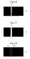
- the GSTH processing unit 4b performs the above-described GSTH processing on the line sensor image 21 (step P2). Specifically, an eroded image 22 as shown in Fig. 8 is acquired by performing the processing described above in sections (1) and (2) on the line sensor image 21. Then, an opening image 23 as shown in Fig. 9 is acquired by performing the processing described above in sections (4) and (5) on the eroded image 22, and the processing to subtract the opening image 23 from the line sensor image 21 is carried out. Thus, a GSTH image 24 as shown in Fig. 10 is obtained. It is apparent from Fig.
- trolley wire worn section a worn section 7a of the trolley wire 7 is emphasized in comparison with the line sensor image 21 while the object 9 other than the trolley wire 7 captured in the background is removed therefrom.
- the binarization processing unit 4c performs the binarization processing on the GSTH image 24 (step P3). It is thus possible to obtain a binarized image 25 in which only the trolley wire worn surface 7a is extracted as shown in Fig. 11 .
- the trolley wire worn section edge detecting unit 4d performs the processing to extract boundaries between the black representing the background and the white representing the trolley wire worn surface 7a in the binarized image 25, respectively as left and right edge points 10L, 10R as shown in Fig. 12 (step P4).
- the edge data can be obtained.
- the trolley wire worn section width calculating unit 4e performs the processing to calculate a distance between the left and right edge points 10L, 10R as the width of the trolley wire worn surface 7a on the image, and then to convert this width into the actual amount of wear of the trolley wire 7 (step P5).
- the measurement computer 4 of this embodiment can measure the amount of wear of the trolley wire 7 by performing the above-described processing.
- the trolley wire worn surface 7a appears bright because the surface reflects the illumination intensely, whereas side surfaces (hereinafter referred to as trolley wire side surfaces) 7b of the trolley wire 7 appear black due to rust, soot, and the like.
- the trolley wire worn surface 7a has a characteristic of being represented in the form of bright pixels surrounded by dark portions, and is therefore emphasized as a result of the GSTH processing.
- the object 9 captured in the background portion appears black on the line sensor image 21 and is not represented in the form of bright pixels surrounded by dark portions. Hence, the object 9 becomes less noticeable as a consequence of the GSH processing.
- the trolley wire worn surface 7a and the background can be separated from each other even in the case of an image in which the trolley wire worn surface 7a is relatively dark.
- the trolley wire worn surface 7a may be processed into black and merged with the background.
- the trolley wire worn surface 7a and the background can be separated from each other even when there is the object 9 other than the trolley wire 7 captured in the background.
- erroneous detection of the trolley wire worn surface 7a can be reduced.
- the erosion processing and the dilation processing are performed on the gray scale image instead of an image subjected to the binarization processing. Accordingly, the trolley wire worn surface 7a and the background can be separated from each other even in the case of the image in which the trolley wire worn surface 7a is relatively dark.
- FIG. 13 A second embodiment of the trolley wire wear measuring apparatus using image processing according to the present invention will be described by using Fig. 13 to Fig. 16 .
- This embodiment is designed to remove a brightness patch in a background by determining a region having uniform luminance while using standard deviation.
- This embodiment employs a standard deviation background removal processing unit 4f shown in Fig. 13 instead of the GSTH processing unit 4b of the above-described first embodiment.
- the rest of the configuration is substantially the same as the above-described configuration shown in Fig. 1 and Fig. 2 .
- similar components will be denoted by the same reference numerals and overlapped descriptions will be omitted. Instead, different features will mainly be described below.
- the measurement computer 4 includes the line sensor image creating unit 4a, the standard deviation background removal processing unit 4f as the background separation processing means, the binarization processing unit 4c, the trolley wire worn section edge detecting unit 4d, and the trolley wire worn section width calculating unit 4e.
- the standard deviation background removal processing unit 4f performs standard deviation background removal processing on the inputted line sensor image.
- An image (hereinafter referred to as a background removed image) created by the standard deviation background removal processing unit 4f is inputted into the binarization processing unit 4c via the memory M2.
- the binarization processing unit 4c performs the binarization processing on the inputted background removed image, thereby creating the binarized image.
- the created binarized image is inputted into the trolley wire worn section edge detecting unit 4d via the memory M2.
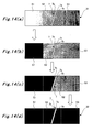
- the standard deviation background removal processing unit 4f in the trolley wire wear measuring apparatus using image processing of this embodiment divides a line sensor image 31 into arbitrary segments (a first segment S1, a second segment S2, and a third segment S3 in this embodiment), and performs the standard deviation background removal processing on each of the segments.
- the standard deviation background removal processing is performed on the first segment S1.
- the first segment S1 does not capture the trolley wire 7 as a target object and its standard deviation value is therefore low.
- the entire first segment S1 is determined as a background.
- the first segment S1 thus determined as the background is blackened as a blackened segment so as not to affect the subsequent processing ( Fig. 14(b) ).
- the standard deviation background removal processing is performed on the second segment S2.
- the second segment S2 captures the trolley wire 7 and its standard deviation value is therefore high.
- the second segment S2 is determined to capture a certain structure (which is the trolley wire 7 in this case; hereinafter referred to as a captured object).
- a judgment is made as to whether or not its neighboring segment (the first segment S1 in this case) for which the standard deviation background removal processing has been completed is the blackened segment.
- the neighboring segment is the blackened segment, a region adjacent to the captured object is determined as a background portion and is subjected to blackening processing ( Fig. 14(c) ).
- the blackening processing is not performed when the neighboring segment (the first segment S1 in this case) for which the standard deviation background removal processing has been completed is not the blackened segment.
- the standard deviation background removal processing is performed on the third segment S3.
- the third segment S3 does not capture the trolley wire 7 and its standard deviation value is therefore low.
- the entire third segment S3 is determined as a background and is blackened as a blackened segment, like the first segment S1.
- a judgment is made as to whether or not its neighboring segment (the second segment S2 in this case) for which the standard deviation background removal processing has been completed is the blackened segment.
- a region between the captured object in the neighboring segment and the third segment S3 is regarded as a background portion and is subjected to blackening processing ( Fig. 14(d) ).
- the third segment S3 is subjected to the blackening processing when the neighboring segment (the second segment S2 in this case) for which the standard deviation background removal processing has been completed is the blackened segment.
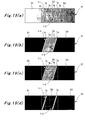
- a region between the two trolley wires 7-1, 7-2 is unlikely to be blackened as shown in Fig. 15 (b) as a result of performing the above-described processing.
- the region which has not been blackened is subdivided into subdivided segments as shown in Fig. 15 (c) , and the subdivided segments are subjected to the similar processing.
- the captured objects and the background are separated from one another as shown in Fig. 15(d) by performing the blackening processing on the background between the two captured objects.
- the line sensor image may be divided into segments in such a manner as to satisfy the following formula (1): B ⁇ L / 2 where the size of division of the segments is B and the minimum distance between the captured objects is L.
- the above-described processing makes it possible to obtain a background removed image 32 from which the brightness patch on the background is removed.
- the binarizing process unit 4c performs the binarization processing on the inputted background removed image 32, thereby creating the binarized image.
- the created binarized image is inputted into the trolley wire worn section edge detecting unit 4d via the memory M2.
- the measurement computer 4 of this embodiment first causes the line sensor image creating unit 4a to perform the processing to create the line sensor image 31 by arranging image signals, which are inputted from the line sensor camera 2, in time series (step P11).
- the standard deviation background removal processing unit 4f performs the above-described standard deviation background removal processing on the line sensor image 31 (step P12).
- the binarization processing unit 4c performs the binarization processing on the background removed image 32 obtained in step P12 (step P13).
- the binarized image is obtained.
- the trolley wire worn section edge detecting unit 4d performs the processing to extract boundaries between the black representing the background of the binarized image and the white representing the trolley wire worn surface 7a therein, respectively as the left and right edge points (step P14). Thus, the edge data can be obtained.
- the trolley wire worn section width calculating unit 4e performs the processing to calculate the distance between the left and right edge points as the width of the trolley wire worn surface 7a on the image, and then to convert this width into the actual amount of wear of the trolley wire 7 (step P15).
- the measurement computer 4 of this embodiment can measure the amount of wear of the trolley wire 7 by performing the above-described processing.
- this embodiment is designed to divide the image into the arbitrary segments, to obtain the standard deviation in each segment, and to check the degree of variation in luminance therein.
- a segment having the large degree of variation in luminance is determined as a segment capturing the trolley wire, and a segment having the low degree of variation in luminance is determined as a background.
- the segment determined as the background is subjected to the blackening processing so as not to affect the subsequent processing. The clarification of the segment as being the background reduces erroneous detection of the trolley wire.
- the blackening processing is also performed in a region between the neighboring segment and a captured object in the segment.
- a blank region pixels representing the background but not being blackened
- pixels each having a luminance difference equal to or above a certain value as compared to an average luminance value of the blackened segment are detected as a position of the captured object.
- the trolley wire worn surface 7a and the background can be separated from each other even when there is a brightness patch on the background.
- erroneous detection of the trolley wire worn surface 7a can be reduced.
- the trolley wire worn surface and the background can be reliably separated from each other, since the portion up to the captured object in the segment is blackened if its neighboring segment is the blackened segment.
- the standard deviation background removal processing unit 4f blackens the region regarded as the background.
- the invention is not limited only to the configuration to blacken the region regarded as the background. Needless to say, various changes are possible without departing from the gist of the invention.
- the region regarded as the background can be stored as mask pixels in a memory space, and such mask pixels can be defined as pixels on which no subsequent processing is performed.
- FIG. 17 and Fig. 18 A third embodiment of the trolley wire wear measuring apparatus using image processing according to the present invention will be described by using Fig. 17 and Fig. 18 .
- This embodiment is an example in which the standard deviation background removal processing unit 4f of the above-described second embodiment shown in Fig. 13 is added to the measurement computer 4 of the above-described first embodiment shown in Fig. 2 .
- the rest of the configuration is substantially the same as the configuration of the above-described first embodiment.
- similar components will be denoted by the same reference numerals and overlapped descriptions will be omitted. Instead, different features will mainly be described below.
- the measurement computer 4 includes the line sensor image creating unit 4a, the GSTH processing unit 4b, the standard deviation background removal processing unit 4f, the binarization processing unit 4c, the trolley wire worn section edge detecting unit 4d, and the trolley wire worn section width calculating unit 4e.
- the GSTH processing unit 4b performs the GSTH processing on the inputted line sensor image.
- the GSTH image thus created is inputted into the standard deviation background removal processing unit 4f via the memory M2.
- the standard deviation background removal processing unit f performs the standard deviation background removal processing on the inputted GSTH image.
- the background removed image thus created is inputted into the binarization processing unit 4c via the memory M2.
- the binarization processing unit 4c performs the binarization processing on the inputted background removed image, thereby creating the binarized image.
- the created binarized image is inputted into the trolley wire worn section edge detecting unit 4d via the memory M2.
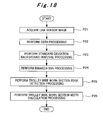
- the measurement computer 4 of this embodiment first causes the line sensor image creating unit 4a to perform the processing to create the line sensor image 31 by arranging image signals, which are inputted from the line sensor camera 2, in time series (step P21).
- the GSTH process unit 4b performs the GSTH processing on the line sensor image (step P22).
- the GSTH image is obtained.
- the standard deviation background removal processing unit 4f performs the standard deviation background removal processing on the GSTH image (step P23).
- the background removed image is obtained.
- the binarization processing unit 4c performs the binarization processing on the background removed image obtained in step P23 (step P24). Thus, the binarized image is obtained.
- the trolley wire worn section edge detecting unit 4d performs the processing to extract the boundaries between the black representing the background of the binarized image and the white representing the trolley wire worn surface 7a therein, respectively as the left and right edge points (step P25). Thus, the edge data can be obtained.
- the trolley wire worn section width calculating unit 4e performs the processing to calculate the distance between the left and right edge points as the width of the trolley wire worn surface 7a on the image, and then to convert this width into the actual amount of wear of the trolley wire 7 (step P26).
- the measurement computer 4 of this embodiment can measure the amount of wear of the trolley wire 7 by performing the above-described processing.
- the trolley wire wear measuring apparatus using image processing of this embodiment can further improve accuracy in comparison with the first embodiment or the second embodiment since the apparatus can remove both a captured object other than the trolley wire and a brightness patch.
- the apparatus can perform the trolley wire wear measurement with higher accuracy by: firstly removing the captured object other than the trolley wire 7 by performing the GSTH processing; and then performing the standard deviation background removal processing.
- this embodiment may also be designed to allow an operator to select the necessities of the GSTH processing and of the standard deviation background removal processing depending on a shooting environment and a shooting condition (by setting ON/OFF of the processing in a setting file, for example). It is needless to say that various changes are possible within the scope not departing from the gist of the present invention.
- the present invention is suitable for application to a trolley wire wear measuring apparatus using image processing.
Landscapes
- Engineering & Computer Science (AREA)
- Physics & Mathematics (AREA)
- General Physics & Mathematics (AREA)
- Manufacturing & Machinery (AREA)
- Mechanical Engineering (AREA)
- Length Measuring Devices By Optical Means (AREA)
- Quality & Reliability (AREA)
- Computer Vision & Pattern Recognition (AREA)
- Theoretical Computer Science (AREA)
- Image Processing (AREA)
Abstract
Description
- The present invention relates to a trolley wire wear measuring apparatus using image processing, or more specifically, to a trolley wire wear measuring apparatus using image processing configured to perform wear measurement robustly against various backgrounds in the daytime.
- A conventional trolley wire wear measuring apparatus using image processing is configured to perform binarization processing on an image acquired from a line sensor; reverse, as a sky portion, each white region larger in size than a thickness parameter of the trolley wire into a black region; extract only a trolley wire worn surface; and perform the trolley wire wear measurement (see
Patent Document 1, for example). - In addition, there is an apparatus configured to further perform binarization processing on the image remaining after the sky portions are removed in the method described in
Patent Document 1, and thereby to separate side surfaces of the trolley wire from the worn surface thereof. Thus, even when the trolley wire worn surface appears relatively dark in the image, the apparatus extracts only the trolley wire worn surface and perform the trolley wire wear measurement (seePatent Document 2, for example). - Meanwhile, there is also an apparatus designed to set a mask on the basis of a preset gray scale threshold such that background portions can be excluded from a processing target (see
Patent Document 3, for example). -
- Patent Document 1: Japanese Patent Application Publication No.
2007-271445 - Patent Document 2: Japanese Patent Application Publication No.
2008-089524 - Patent Document 3: Japanese Patent Application Publication No.
2006-250775 - The apparatuses described in
Patent Documents - Meanwhile, according to the invention described in
Patent Document 3, the background is masked on the basis of the given gray scale threshold and thereby is covered with the mask. However, if a captured object or a brightness patch exists in the background poses, the apparatus may fail to mask a background region properly by using the given gray scale threshold and to separate the trolley wire and the background from each other. - As described above, if a captured object or a brightness patch exists in the background, the conventional methods cannot accurately separate the trolley wire and the background from each other by binarizing the image.
- In view of the above, an objective of the present invention is to provide a trolley wire wear measuring apparatus using image processing, which is capable of eliminating effects of a captured object other than a trolley wire or a brightness patch captured in a background of an image acquired from a line sensor camera, thereby separating a trolley wire and the object other than the trolley wire from each other, and thus reducing erroneous detection of a trolley wire worn surface.
- A trolley wire wear measuring apparatus using image processing according to a first aspect of the invention for the purpose of solving the foregoing problems is a trolley wire wear measuring apparatus using image processing which includes: a line sensor camera installed on a roof of a vehicle with its scan line direction set horizontal and perpendicular to a traveling direction of the vehicle and configured to shoot a trolley wire; illuminating means also installed on the roof of the vehicle and configured to illuminate the trolley wire; and image processing means installed inside the vehicle. The trolley wire wear measuring apparatus is characterized in that the image processing means comprises: line sensor image creating means configured to create a line sensor image in which image signals inputted from the line sensor camera are arranged in time series; background separation processing means configured to separate an inputted image into the trolley wire and a background; binarization processing means configured to perform binarization processing on an inputted image and create a binarized image; trolley wire worn section edge detecting means configured to detect edges on two sides of a worn section of the trolley wire from an inputted image; and trolley wire worn section width calculating means configured to detect an amount of wear of the trolley wire using positions of the edges on the two sides of the worn section.
- A trolley wire wear measuring apparatus using image processing according to a second aspect of the invention for the purpose of solving the foregoing problems is the trolley wire wear measuring apparatus using image processing according to the first aspect of the invention, characterized in that the background separation processing means is GSTH processing means configured to perform GSTH processing on the inputted image to create a GSTH image in which the worn section of the trolley wire in the inputted image is emphasized.
- A trolley wire wear measuring apparatus using image processing according to a third aspect of the invention for the purpose of solving the foregoing problems is the trolley wire wear measuring apparatus using image processing according to the second aspect of the invention, characterized in that: the GSTH processing means performs the GSTH processing on the line sensor image to create the GSTH image in which the worn section of the trolley wire in the line sensor image is emphasized; the binarization processing means performs the binarization processing on the GSTH image to create the binarized image; and the trolley wire worn section edge detecting means detects the edges from the binarized image.
- A trolley wire wear measuring apparatus using image processing according to a fourth aspect of the invention for the purpose of solving the foregoing problems is the trolley wire wear measuring apparatus using image processing according to the first aspect of the invention, characterized in that the background separation processing means is standard deviation background removal processing means configured to divide the inputted image into arbitrary segments and perform standard deviation background removal processing on each segment, thereby creating a background removed image, the standard deviation background removal processing including: for each segment, judging whether or not a target object is captured in the segment; when the target object is captured in the segment and the target object is not captured in its neighboring segment, regarding a region between the neighboring segment and the target object as the background; and when the target object is not captured in the segment and the target object is captured in its neighboring segment, regarding the segment and a region between the target object in the neighboring segment and the segment as the background.
- A trolley wire wear measuring apparatus using image processing according to a fifth aspect of the invention for the purpose of solving the foregoing problems is the trolley wire wear measuring apparatus using image processing according to the fourth aspect of the invention, characterized in that when a region not regarded as the background exists in one of the segments subjected to the standard deviation background removal processing, the standard deviation background removal processing means subdivides the segment into subdivided segments, and performs the standard deviation background removal processing on each subdivided segment, thereby creating the background removed image, the standard deviation background removal processing including: for each subdivided segment, judging whether or not the target object is captured in the segment; when the target object is captured in the segment and the target object is not captured in its neighboring segment, regarding a region between the neighboring segment and the target object as the background; and when the target object is not captured in the segment and the target object is captured in its neighboring segment, regarding the segment and a region between the target object in the neighboring segment and the segment as the background.
- A trolley wire wear measuring apparatus using image processing according to a sixth aspect of the invention for the purpose of solving the foregoing problems is the trolley wire wear measuring apparatus using image processing according to the fourth aspect of the invention, characterized in that each arbitrary segment has a size that does not allow the target object to exist across a boundary between continuous segments.
- A trolley wire wear measuring apparatus using image processing according to a seventh aspect of the invention for the purpose of solving the foregoing problems is the trolley wire wear measuring apparatus using image processing according to any one of the fourth to sixth aspects of the invention, characterized in that: the standard deviation background removal processing means performs the standard deviation background removal processing on the line sensor image to create the background removed image which includes the trolley wire extracted from the line sensor image; the binarization processing means performs the binarization processing on the background removed image to create the binarized image; and the trolley wire worn section edge detecting means detects the edges from the binarized image.
- A trolley wire wear measuring apparatus using image processing according to an eighth aspect of the invention for the purpose of solving the foregoing problems is the trolley wire wear measuring apparatus using image processing according to the second or third aspect of the invention, characterized in that: the image processing means further comprises standard deviation background removal processing means, as the background separation processing means, configured to divide the inputted image into arbitrary segments and perform standard deviation background removal processing on each of the segments, thereby creating a background removed image, the standard deviation background removal processing including: for each of the segments, judging whether or not a target object is captured in the segment; when the target object is captured in the segment and the target object is not captured in its neighboring segment, regarding a region between the neighboring segment and the target object as the background; and when the target object is not captured in the segment and the target object is captured in its neighboring segment, regarding the segment and a region between the target object in the neighboring segment and the segment as the background.
- A trolley wire wear measuring apparatus using image processing according to a ninth aspect of the invention for the purpose of solving the foregoing problems is the trolley wire wear measuring apparatus using image processing according to the eighth aspect of the invention, characterized in that when a region not regarded as the background exists in one of the segments subjected to the standard deviation background removal processing, the standard deviation background removal processing means subdivides the segment into subdivided segments and performs the standard deviation background removal processing on each of the subdivided segments, thereby creating the background removed image, the standard deviation background removal processing including: for each of the subdivided segment, judging whether or not the target object is captured in the segment; when the target object is captured in the segment and the target object is not captured in its neighboring segment, regarding a region between the neighboring segment and the target object as the background; and when the target object is not captured in the segment and the target object is captured in its neighboring segment, regarding the segment and a region between the target object in the neighboring segment and the segment as the background.
- A trolley wire wear measuring apparatus using image processing according to a tenth aspect of the invention for the purpose of solving the foregoing problems is the trolley wire wear measuring apparatus using image processing according to the eighth aspect of the invention, characterized in that each arbitrary segment has a size that does not allow the target object to exist across the boundary between the continuous segments.
- A trolley wire wear measuring apparatus using image processing according to an eleventh aspect of the invention for the purpose of solving the foregoing problems is the trolley wire wear measuring apparatus using image processing according to any one of the eighth to tenth aspects of the invention, characterized in that: the GSTH processing means performs the GSTH processing on the line sensor image to create the GSTH image in which the worn section of the trolley wire in the line sensor image is emphasized; the standard deviation background removal processing means performs the standard deviation background removal processing on the GSTH image to create the background removed image which includes the trolley wire extracted from in the GSTH image; the binarization processing means performs the binarization processing on the background removed image to create the binarized image; and the trolley wire worn section edge detecting means detects the edges from the binarized image.
- The above-described trolley wire wear measuring apparatus using image processing according to the first aspect of the invention includes: the line sensor camera installed on the roof of the vehicle with its scan line direction set horizontal and perpendicular to the traveling direction of the vehicle and configured to shoot the trolley wire; the illuminating means also installed on the roof of the vehicle and configured to illuminate the trolley wire; and the image processing means installed inside the vehicle. Here, the image processing means comprises: the line sensor image creating means configured to create the line sensor image in which the image signal inputted from the line sensor camera are arranged in time series; the background separation processing means configured to separate the inputted image into the trolley wire and the background; the binarization processing means configured to perform the binarization processing on the inputted image to create the binarized image; the trolley wire worn section edge detecting means configured to detect the edges on the two sides of the worn section of the trolley wire from the inputted image; and the trolley wire worn section width calculating means configured to detect the amount of wear of the trolley wire using the positions of the edges on the two sides of the worn section. Thus, the apparatus can separate the trolley wire worn surface and the background from each other and reduce erroneous detection of the trolley wire worn surface.
- According to the above-described trolley wire wear measuring apparatus using image processing of the second aspect of the invention, the background separation processing means is the GSTH processing means configured to perform the GSTH processing on the inputted image to create the GSTH image in which the worn section of the trolley wire in the image is emphasized. Thus, it is possible to reduce erroneous detection of the trolley wire worn surface by emphasizing the trolley wire worn surface in the inputted image by performing the GSTH processing on the inputted image, while removing an object captured in the background.
- In addition, according to the trolley wire wear measuring apparatus using image processing of the third aspect of the invention, the GSTH processing means performs the GSTH processing on the line sensor image to create the GSTH image in which the worn section of the trolley wire in the line sensor image is emphasized. Then, the binarization processing means performs the binarization processing on the GSTH image to create the binarized image, and the trolley wire worn section edge detecting means detects the edges from the binarized image. Thus, even when the trolley wire worn surface appears dark in the inputted image, the execution of the GSTH processing before performing the binarization processing makes it possible to emphasize the trolley wire worn surface and thus to separate the worn surface from the background.
- According to the trolley wire wear measuring apparatus using image processing of the fourth aspect of the invention, the background separation processing means is the standard deviation background removal processing means configured to divide the inputted image into the arbitrary segments and perform the standard deviation background removal processing on each of the segments, thereby creating the background removed image. Here, the standard deviation background removal processing includes: for each segment, judging whether or not the target object is captured in the segment; when the target object is captured in the segment and the target object is not captured in its neighboring segment, regarding the region between the neighboring segment and the target object as the background; and when the target object is not captured in the segment and the target object is captured in its neighboring segment, regarding the segment and a region between the target object in the neighboring segment and the segment as the background. Thus, even when there is a brightness patch in the background of the inputted image, the trolley wire can be identified by performing the standard deviation background removal processing on the inputted image. Hence, it is possible to reduce erroneous detection of the trolley wire worn surface.
- According to the trolley wire wear measuring apparatus using image processing of the fifth aspect of the invention, when the region not regarded as the background exists in one of the segments subjected to the standard deviation background removal processing, the standard deviation background removal processing means subdivides the certain segment into the subdivided segments and performs the standard deviation background removal processing on each of the subdivided segments, thereby creating the background removed image. Here, the standard deviation background removal processing includes: for each of the subdivided segments, judging whether or not the target object is captured in the segment; when the target object is captured in the segment and the target object is not captured in its neighboring segment, regarding the region between the neighboring segment and the target object as the background; and when the target object is not captured in the segment and the target object is captured in its neighboring segment, regarding the segment as well as the region between the target object in the neighboring segment and the segment as the background. Thus, the target object and the background can reliably be separated from each other.
- According to the trolley wire wear measuring apparatus using image processing of the sixth aspect of the invention, each arbitrary segment has the size that does not allow the target object to exist across the boundary between the continuous segments. Thus, the target object and the background can be separated from each other by performing the processing just once.
- According to the trolley wire wear measuring apparatus using image processing of the seventh aspect of the invention, the standard deviation background removal processing means performs the standard deviation background removal processing on the line sensor image to create the background removed image which includes the trolley wire extracted from the line sensor image. Then, the binarization processing means performs the binarization processing on the background removed image to create the binarized image, and the trolley wire worn section edge detecting means detects the edges from the binarized image. Thus, even when there is a brightness patch in the background of the inputted image, the trolley wire can be clearly identified by performing the standard deviation background removal processing before performing the binarization processing.
- According to the trolley wire wear measuring apparatus using image processing of the eighth aspect of the invention, the image processing means further comprises the standard deviation background removal processing means, as the background separation processing means, configured to divide the inputted image into the arbitrary segments and perform the standard deviation background removal processing on each of the segments, thereby creating the background removed image. Here, the standard deviation background removal processing includes: for each of the segments, judging whether or not the target object is captured in the segment; when the target object is captured in the segment and the target object is not captured in its neighboring segment, regarding the region between the neighboring segment and the target object; and when the target object is not captured in the segment and the target object is captured in its neighboring segment, regarding the segment and a region between the target object in the neighboring segment and the segment as the background. Thus, it is possible to further reduce erroneous detection of the trolley wire worn surface by using the GSTH processing and the standard deviation background removal processing in combination.
- According to the trolley wire wear measuring apparatus using image processing of the ninth aspect of the invention, when the region not regarded as the background exists in one of the segments subjected to the standard deviation background removal processing, the standard deviation background removal processing means subdivides the segment into subdivided segments and performs the standard deviation background removal processing on each of the subdivided segments, thereby creating the background removed image. Here, the standard deviation background removal processing includes: for each of the subdivided segment, judging whether or not the target object is captured in the segment; when the target object is captured in the segment and the target object is not captured in its neighboring segment, regarding a region between the neighboring segment and the target object as the background; and when the target object is not captured in the segment and the target object is captured in its neighboring segment, regarding the segment and a region between the target object in the neighboring segment and the segment as the background. Thus, the target object and the background can reliably be separated from each other.
- According to the trolley wire wear measuring apparatus using image processing of the tenth aspect of the invention, each arbitrary segment has the size that does not allow the target object to exist across the boundary between the continuous segments. Thus, the target object and the background can be separated from each other by performing the processing just once.
- According to the trolley wire wear measuring apparatus using image processing of the eleventh aspect of the invention, the GSTH processing means performs the GSTH processing on the line sensor image to create the GSTH image in which the worn section of the trolley wire in the line sensor image is emphasized. Then, the standard deviation background removal processing means performs the standard deviation background removal processing on the GSTH image to create the background removed image which includes the trolley wire extracted from the GSTH image. Thereafter, the binarization processing means performs the binarization processing on the background removed image to create the binarized image, and the trolley wire worn section edge detecting means detects the edges from the binarized image. Thus, it is possible to further improve accuracy of the trolley wire wear measurement by subjecting the line sensor image to the GSTH processing and then to the standard deviation background removal processing.
-
- [
Fig. 1] Fig. 1 is a schematic diagram showing an example of the installation of a trolley wire wear measuring apparatus using image processing according to a first embodiment of the present invention. - [
Fig. 2] Fig. 2 is a block diagram showing a schematic configuration of a measurement computer of the trolley wire wear measuring apparatus using image processing according to the first embodiment of the present invention. - [
Fig. 3] Figs. 3(a) and 3(b) are explanatory views showing an example of erosion processing in the first embodiment of the present invention. - [
Fig. 4] Figs. 4(a) and 4(b) are explanatory views showing an example of dilation processing in the first embodiment of the present invention. - [
Fig. 5] Fig. 5 is an explanatory view showing an example of a GSTH image in the first embodiment of the present invention. - [
Fig. 6] Fig. 6 is a flowchart showing a flow of trolley wire wear measurement processing according to the first embodiment of the present invention. - [
Fig. 7] Fig. 7 is an explanatory view showing an example of a line sensor image according to the first embodiment of the present invention. - [
Fig. 8] Fig. 8 is an explanatory view showing an example of an eroded image according to the first embodiment of the present invention. - [
Fig. 9] Fig. 9 is an explanatory view showing an example of an opening image according to the first embodiment of the present invention. - [
Fig. 10] Fig. 10 is an explanatory view showing an example of the GSTH image according to the first embodiment of the present invention. - [
Fig. 11] Fig. 11 is an explanatory view showing an example of a binarized image according to the first embodiment of the present invention. - [
Fig. 12] Fig. 12 is an explanatory view showing an example of edge extraction according to the first embodiment of the present invention. - [
Fig. 13] Fig. 13 is a block diagram showing a schematic configuration of a measurement computer of a trolley wire wear measuring apparatus using image processing according to a second embodiment of the present invention. - [
Fig. 14] Figs. 14 (a) to 14(d) are explanatory views showing an example of standard deviation background removal processing according to the second embodiment of the present invention. - [
Fig. 15] Figs. 15(a) to 15(d) are explanatory views showing another example of the standard deviation background removal processing according to the second embodiment of the present invention. - [
Fig. 16] Fig. 16 is a flowchart showing a flow of trolley wire wear measurement processing according to the second embodiment of the present invention. - [
Fig. 17] Fig. 17 is a block diagram showing a schematic configuration of a measurement computer of a trolley wire wear measuring apparatus using image processing according to a third embodiment of the present invention. - [
Fig. 18] Fig. 18 is a flowchart showing a flow of trolley wire wear measurement processing according to the third embodiment of the present invention. - A trolley wire wear measuring apparatus using image processing according to the present invention will be described below in detail with reference to the drawings.
- A first embodiment of a trolley wire wear measuring apparatus using image processing according to the present invention will be described by using
Fig. 1 to Fig. 12 . This embodiment is designed to remove an object other than a trolley wire captured on a background by performing gray scale-top hat processing (hereinafter referred to as "GSTH processing"). - As shown in
Fig. 1 , aline sensor camera 2 andlighting device 3 are installed on a roof of avehicle 1 in this embodiment. In addition, ameasurement computer 4 and arecording device 5 are disposed inside thevehicle 1. - The direction of the
line sensor camera 2 is set in order that: theline sensor camera 2 can shoot vertically upward; and its scan line direction is aligned with a direction of railroad ties provided forrails 6, or in other words, with a direction orthogonal to a traveling direction of thevehicle 1. Thus, the scan line of theline sensor camera 2 intersects atrolley wire 7. - The
lighting device 3 is installed to illuminate a worn section (i.e., a surface coming into contact with a pantograph 8) of thetrolley wire 7 to be shot with theline sensor camera 2. - Meanwhile, as shown in
Fig. 2 , themeasurement computer 4 includes a line sensorimage creating unit 4a as line sensor image creating means, aGSTH processing unit 4b as background separation processing means, abinarization processing unit 4c as binarization processing means, a trolley wire worn sectionedge detecting unit 4d as trolley wire worn section edge detecting means, and a trolley wire worn sectionwidth calculating unit 4e as trolley wire worn section width calculating means. - The line sensor
image creating unit 4a creates a line sensor image (an image of a plane) by arranging image signals (luminance signals of scan lines), which are inputted from the line sensor, in time series. The created line sensor image is inputted into theGSTH processing unit 4b via memories M1, M2. - The
GSTH processing unit 4b performs the GSTH processing on the inputted line sensor image. - The line sensor image subjected to the GSTH processing (hereinafter referred to as a GSTH image) by the
GSTH processing unit 4b is inputted into thebinarization processing unit 4c via the memory M2. - As suggested by the name, the GSTH processing is intended to perform top hat processing on a gray scale image. The top hat processing is processing to subtract an image that undergoes opening (processing by erosion a certain number of times and subsequent dilation the same number of times) from an original image.
- The GSTH processing by the
GSTH processing unit 4b will be described below in detail by usingFig. 3(a) to Fig. 5 . TheGSTH processing unit 4b performs the processing in the following flow. - (1) As shown in
Fig. 3(b) , for a range (hereinafter referred to as a search range) SD-1 of N pixels (three pixels inFig. 3 (b) ) in anoriginal image 11 illustrated inFig. 3 (a) , a luminance value of the darkest pixel is written in a separate buffer (hereinafter referred to as an erosion processing buffer) 12-1. - (2) The search range is then shifted (to search ranges SD-2 to SD-M in
Fig. 3(b) ). For each of the search ranges SD-2 to SD-M, a luminance value of the darkest pixel is written in a corresponding one of the erosion processing buffers 12-2 to 12-M. - (3) Thus, an eroded
image 12 shown inFig. 4 (a) is created. - (4) Subsequently, as shown in
Fig. 4(b) , for a range (hereinafter a "search range") SL-1 of N pixels (three pixels in this embodiment) in the erodedimage 12, a luminance value of the brightest pixel is written in a separate buffer (hereinafter referred to as a dilation processing buffer) 13-1. - (5) The search range is then shifted (to search ranges 13-2 to 13-M in
Fig. 4(b) ). For each of the search ranges SL-2 to SL-M, a luminance value of the brightest pixel is written in a corresponding one of the dilation processing buffers 13-2 to 13-M. - (6) Thus, an
opening image 13 is created. - (7) Subsequently, the opening
image 13 created in section (6) is subtracted from theoriginal image 11. - The execution of the processing described above provides a
GSTH image 14 in which bright pixels surrounded by dark portions in the image are emphasized as shown inFig. 5 . - The
binarization processing unit 4c performs binarization processing on the inputtedGSTH image 14, thereby creating a binarized image. The created binarized image is inputted into the trolley wire worn sectionedge detecting unit 4d via the memory M2. - The trolley wire worn section
edge detecting unit 4d subjects the inputted binarized image to such processing that detects a point where black turns into white when searching a certain line from the left side, for example, as an edge point on the left side, and subsequently detects a point where white turns into black as an edge point on the right side. This processing is performed on each line of the image from the top to the bottom. The information on the detected edge points (hereinafter referred to as edge data) is inputted into the trolley wire worn sectionwidth calculating unit 4e via the memory M2. - The trolley wire worn section
width calculating unit 4e calculates a width between the right and left edges on the line sensor image on the basis of the inputted edge data, and then converts the width into an actual amount of wear of thetrolley wire 7. The calculated amount of wear of thetrolley wire 7 is inputted as trolley wire worn width data into therecording device 5 via the memory M2. - In addition to the trolley wire worn width data mentioned above, the line sensor image, the GSTH image, the binarized image, the edge data, and the like are recorded in the
recording device 5 via the memories M1, M2. - A flow of image processing by the
measurement computer 4 of the trolley wire wear measuring apparatus using image processing of this embodiment will be described by usingFig. 6 to Fig. 12 . - As shown in
Fig. 6 , themeasurement computer 4 of this embodiment first causes the line sensorimage creating unit 4a to perform the processing to create aline sensor image 21 as shown inFig. 7 by arranging image signals, which are inputted from theline sensor camera 2, in time series (step P1). - Here, in addition to the
trolley wire 7, theline sensor image 21 created by the line sensorimage creating unit 4a may capture anobject 9 other than thetrolley wire 7, such as a roof or an overhead line structure as shown inFig. 7 . - Following step P1, the
GSTH processing unit 4b performs the above-described GSTH processing on the line sensor image 21 (step P2). Specifically, an erodedimage 22 as shown inFig. 8 is acquired by performing the processing described above in sections (1) and (2) on theline sensor image 21. Then, anopening image 23 as shown inFig. 9 is acquired by performing the processing described above in sections (4) and (5) on the erodedimage 22, and the processing to subtract theopening image 23 from theline sensor image 21 is carried out. Thus, aGSTH image 24 as shown inFig. 10 is obtained. It is apparent fromFig. 10 that, in theGSTH image 24, only a worn section (hereinafter referred to as a trolley wire worn section) 7a of thetrolley wire 7 is emphasized in comparison with theline sensor image 21 while theobject 9 other than thetrolley wire 7 captured in the background is removed therefrom. - Following step P2, the
binarization processing unit 4c performs the binarization processing on the GSTH image 24 (step P3). It is thus possible to obtain abinarized image 25 in which only the trolley wire wornsurface 7a is extracted as shown inFig. 11 . - Following step P3, the trolley wire worn section
edge detecting unit 4d performs the processing to extract boundaries between the black representing the background and the white representing the trolley wire wornsurface 7a in thebinarized image 25, respectively as left and right edge points 10L, 10R as shown inFig. 12 (step P4). Thus, the edge data can be obtained. - Following step P4, the trolley wire worn section
width calculating unit 4e performs the processing to calculate a distance between the left and right edge points 10L, 10R as the width of the trolley wire wornsurface 7a on the image, and then to convert this width into the actual amount of wear of the trolley wire 7 (step P5). - The
measurement computer 4 of this embodiment can measure the amount of wear of thetrolley wire 7 by performing the above-described processing. - The trolley wire worn
surface 7a appears bright because the surface reflects the illumination intensely, whereas side surfaces (hereinafter referred to as trolley wire side surfaces) 7b of thetrolley wire 7 appear black due to rust, soot, and the like. In other words, the trolley wire wornsurface 7a has a characteristic of being represented in the form of bright pixels surrounded by dark portions, and is therefore emphasized as a result of the GSTH processing. In the meantime, theobject 9 captured in the background portion appears black on theline sensor image 21 and is not represented in the form of bright pixels surrounded by dark portions. Hence, theobject 9 becomes less noticeable as a consequence of the GSH processing. - In addition, since the GSTH processing is performed before performing the binarization processing, the erosion processing and the dilation processing are performed on the gray scale image. Thus, the trolley wire worn
surface 7a and the background can be separated from each other even in the case of an image in which the trolley wire wornsurface 7a is relatively dark. On the other hand, if the binarization processing is performed directly on the image in which the trolley wire wornsurface 7a is relatively dark, the trolley wire wornsurface 7a may be processed into black and merged with the background. - According to the trolley wire wear measuring apparatus using image processing of the above-described embodiment, the trolley wire worn
surface 7a and the background can be separated from each other even when there is theobject 9 other than thetrolley wire 7 captured in the background. Thus, erroneous detection of the trolley wire wornsurface 7a can be reduced. - In addition, the erosion processing and the dilation processing are performed on the gray scale image instead of an image subjected to the binarization processing. Accordingly, the trolley wire worn
surface 7a and the background can be separated from each other even in the case of the image in which the trolley wire wornsurface 7a is relatively dark. - A second embodiment of the trolley wire wear measuring apparatus using image processing according to the present invention will be described by using
Fig. 13 to Fig. 16 . This embodiment is designed to remove a brightness patch in a background by determining a region having uniform luminance while using standard deviation. - This embodiment employs a standard deviation background
removal processing unit 4f shown inFig. 13 instead of theGSTH processing unit 4b of the above-described first embodiment. The rest of the configuration is substantially the same as the above-described configuration shown inFig. 1 andFig. 2 . In the following, similar components will be denoted by the same reference numerals and overlapped descriptions will be omitted. Instead, different features will mainly be described below. - As shown in
Fig. 13 , themeasurement computer 4 includes the line sensorimage creating unit 4a, the standard deviation backgroundremoval processing unit 4f as the background separation processing means, thebinarization processing unit 4c, the trolley wire worn sectionedge detecting unit 4d, and the trolley wire worn sectionwidth calculating unit 4e. - The standard deviation background
removal processing unit 4f performs standard deviation background removal processing on the inputted line sensor image. An image (hereinafter referred to as a background removed image) created by the standard deviation backgroundremoval processing unit 4f is inputted into thebinarization processing unit 4c via the memory M2. - The
binarization processing unit 4c performs the binarization processing on the inputted background removed image, thereby creating the binarized image. The created binarized image is inputted into the trolley wire worn sectionedge detecting unit 4d via the memory M2. - The processing by the standard deviation background
removal processing unit 4f will be described below in detail by usingFig. 14 . As shown inFig. 14 (a) , the standard deviation backgroundremoval processing unit 4f in the trolley wire wear measuring apparatus using image processing of this embodiment divides aline sensor image 31 into arbitrary segments (a first segment S1, a second segment S2, and a third segment S3 in this embodiment), and performs the standard deviation background removal processing on each of the segments. - First of all, the standard deviation background removal processing is performed on the first segment S1. In the example shown in
Fig. 14(a) , the first segment S1 does not capture thetrolley wire 7 as a target object and its standard deviation value is therefore low. As a consequence, the entire first segment S1 is determined as a background. The first segment S1 thus determined as the background is blackened as a blackened segment so as not to affect the subsequent processing (Fig. 14(b) ). - Then, the standard deviation background removal processing is performed on the second segment S2. In the example shown in
Fig. 14(a) , the second segment S2 captures thetrolley wire 7 and its standard deviation value is therefore high. As a consequence, the second segment S2 is determined to capture a certain structure (which is thetrolley wire 7 in this case; hereinafter referred to as a captured object). In the case of the determination that the captured object is captured as described above, a judgment is made as to whether or not its neighboring segment (the first segment S1 in this case) for which the standard deviation background removal processing has been completed is the blackened segment. When the neighboring segment is the blackened segment, a region adjacent to the captured object is determined as a background portion and is subjected to blackening processing (Fig. 14(c) ). On the other hand, the blackening processing is not performed when the neighboring segment (the first segment S1 in this case) for which the standard deviation background removal processing has been completed is not the blackened segment. - Next, the standard deviation background removal processing is performed on the third segment S3. In the example shown in
Fig. 14(a) , the third segment S3 does not capture thetrolley wire 7 and its standard deviation value is therefore low. As a consequence, the entire third segment S3 is determined as a background and is blackened as a blackened segment, like the first segment S1. Furthermore, concerning the segment being other than the first segment S1 and determined as the background, a judgment is made as to whether or not its neighboring segment (the second segment S2 in this case) for which the standard deviation background removal processing has been completed is the blackened segment. When the neighboring segment is not the blackened segment, a region between the captured object in the neighboring segment and the third segment S3 is regarded as a background portion and is subjected to blackening processing (Fig. 14(d) ). On the other hand, only the third segment S3 is subjected to the blackening processing when the neighboring segment (the second segment S2 in this case) for which the standard deviation background removal processing has been completed is the blackened segment. - Here, there may be a case in which, for example when two trolley wires 7-1, 7-2 has been shot as shown in
Fig. 15(a) , two or more captured objects exist in theline sensor image 31 in a way that: the captured objects exist in the respective neighboring segments; or the two captured segments exist in one segment. In such a case, a region between the two trolley wires 7-1, 7-2 is unlikely to be blackened as shown inFig. 15 (b) as a result of performing the above-described processing. In this case, the region which has not been blackened is subdivided into subdivided segments as shown inFig. 15 (c) , and the subdivided segments are subjected to the similar processing. Thus, the captured objects and the background are separated from one another as shown inFig. 15(d) by performing the blackening processing on the background between the two captured objects. - If a distance between the two or more captured objects is predictable in advance when the captured objects are shot in the
line sensor image 31, then it is preferable to set the size of the segments at the time of dividing the line sensor image into the arbitrary segments in such a way that two or more captured objects do not exist in any one segment or in neighboring segments. In this way, it is possible to separate the captured objects and the background from one another by performing the processing just once. Specifically, the line sensor image may be divided into segments in such a manner as to satisfy the following formula (1):
- The above-described processing makes it possible to obtain a background removed
image 32 from which the brightness patch on the background is removed. - The
binarizing process unit 4c performs the binarization processing on the inputted background removedimage 32, thereby creating the binarized image. The created binarized image is inputted into the trolley wire worn sectionedge detecting unit 4d via the memory M2. - A flow of image processing by the
measurement computer 4 of the trolley wire wear measuring apparatus using image processing of this embodiment will be described by usingFig. 16 . - As shown in
Fig. 16 , themeasurement computer 4 of this embodiment first causes the line sensorimage creating unit 4a to perform the processing to create theline sensor image 31 by arranging image signals, which are inputted from theline sensor camera 2, in time series (step P11). - Subsequently, the standard deviation background
removal processing unit 4f performs the above-described standard deviation background removal processing on the line sensor image 31 (step P12). Thereafter, thebinarization processing unit 4c performs the binarization processing on the background removedimage 32 obtained in step P12 (step P13). Thus, the binarized image is obtained. - Following step P13, the trolley wire worn section
edge detecting unit 4d performs the processing to extract boundaries between the black representing the background of the binarized image and the white representing the trolley wire wornsurface 7a therein, respectively as the left and right edge points (step P14). Thus, the edge data can be obtained. - Following step P14, the trolley wire worn section
width calculating unit 4e performs the processing to calculate the distance between the left and right edge points as the width of the trolley wire wornsurface 7a on the image, and then to convert this width into the actual amount of wear of the trolley wire 7 (step P15). - The
measurement computer 4 of this embodiment can measure the amount of wear of thetrolley wire 7 by performing the above-described processing. - In the line sensor image, the sky as the background is represents as a blurry monotonous space when the blue sky and clouds are captured. On the other hand, the
trolley wire 7 as a measurement target is kept in focus and is therefore high in contrast. Using this fact, this embodiment is designed to divide the image into the arbitrary segments, to obtain the standard deviation in each segment, and to check the degree of variation in luminance therein. In this case, a segment having the large degree of variation in luminance is determined as a segment capturing the trolley wire, and a segment having the low degree of variation in luminance is determined as a background. Then, the segment determined as the background is subjected to the blackening processing so as not to affect the subsequent processing. The clarification of the segment as being the background reduces erroneous detection of the trolley wire. - In addition, when a segment not blackened has a neighboring segment which has been subjected to the blackening processing, the blackening processing is also performed in a region between the neighboring segment and a captured object in the segment. In this way, it is possible to fill a blank region (pixels representing the background but not being blackened) defined between the blackened segment and the captured object in the region not blackened, and thereby to further reduce erroneous detection. In this embodiment, pixels each having a luminance difference equal to or above a certain value as compared to an average luminance value of the blackened segment are detected as a position of the captured object.
- According to the trolley wire wear measuring apparatus using image processing of the above-described embodiment, the trolley wire worn
surface 7a and the background can be separated from each other even when there is a brightness patch on the background. Thus, erroneous detection of the trolley wire wornsurface 7a can be reduced. - In addition, even in the segment that is not blackened, the trolley wire worn surface and the background can be reliably separated from each other, since the portion up to the captured object in the segment is blackened if its neighboring segment is the blackened segment.
- This embodiment has described the example in which the standard deviation background
removal processing unit 4f blackens the region regarded as the background. However, the invention is not limited only to the configuration to blacken the region regarded as the background. Needless to say, various changes are possible without departing from the gist of the invention. For instance, the region regarded as the background can be stored as mask pixels in a memory space, and such mask pixels can be defined as pixels on which no subsequent processing is performed. - A third embodiment of the trolley wire wear measuring apparatus using image processing according to the present invention will be described by using
Fig. 17 andFig. 18 . This embodiment is an example in which the standard deviation backgroundremoval processing unit 4f of the above-described second embodiment shown inFig. 13 is added to themeasurement computer 4 of the above-described first embodiment shown inFig. 2 . The rest of the configuration is substantially the same as the configuration of the above-described first embodiment. In the following, similar components will be denoted by the same reference numerals and overlapped descriptions will be omitted. Instead, different features will mainly be described below. - As shown in
Fig. 17 , in this embodiment, themeasurement computer 4 includes the line sensorimage creating unit 4a, theGSTH processing unit 4b, the standard deviation backgroundremoval processing unit 4f, thebinarization processing unit 4c, the trolley wire worn sectionedge detecting unit 4d, and the trolley wire worn sectionwidth calculating unit 4e. - In this embodiment, the
GSTH processing unit 4b performs the GSTH processing on the inputted line sensor image. The GSTH image thus created is inputted into the standard deviation backgroundremoval processing unit 4f via the memory M2. - The standard deviation background removal processing unit f performs the standard deviation background removal processing on the inputted GSTH image. The background removed image thus created is inputted into the
binarization processing unit 4c via the memory M2. - The
binarization processing unit 4c performs the binarization processing on the inputted background removed image, thereby creating the binarized image. The created binarized image is inputted into the trolley wire worn sectionedge detecting unit 4d via the memory M2. - A flow of image processing by the
measurement computer 4 of the trolley wire wear measuring apparatus using image processing of this embodiment will be described by usingFig. 18 . - As shown in
Fig. 18 , themeasurement computer 4 of this embodiment first causes the line sensorimage creating unit 4a to perform the processing to create theline sensor image 31 by arranging image signals, which are inputted from theline sensor camera 2, in time series (step P21). - Subsequently, the
GSTH process unit 4b performs the GSTH processing on the line sensor image (step P22). Thus, the GSTH image is obtained. Thereafter, the standard deviation backgroundremoval processing unit 4f performs the standard deviation background removal processing on the GSTH image (step P23). Thus, the background removed image is obtained. - Then, the
binarization processing unit 4c performs the binarization processing on the background removed image obtained in step P23 (step P24). Thus, the binarized image is obtained. - Following step P24, the trolley wire worn section
edge detecting unit 4d performs the processing to extract the boundaries between the black representing the background of the binarized image and the white representing the trolley wire wornsurface 7a therein, respectively as the left and right edge points (step P25). Thus, the edge data can be obtained. - Following step P25, the trolley wire worn section
width calculating unit 4e performs the processing to calculate the distance between the left and right edge points as the width of the trolley wire wornsurface 7a on the image, and then to convert this width into the actual amount of wear of the trolley wire 7 (step P26). - The
measurement computer 4 of this embodiment can measure the amount of wear of thetrolley wire 7 by performing the above-described processing. - The trolley wire wear measuring apparatus using image processing of this embodiment can further improve accuracy in comparison with the first embodiment or the second embodiment since the apparatus can remove both a captured object other than the trolley wire and a brightness patch.
- In addition, the apparatus can perform the trolley wire wear measurement with higher accuracy by: firstly removing the captured object other than the
trolley wire 7 by performing the GSTH processing; and then performing the standard deviation background removal processing. - Note that this embodiment may also be designed to allow an operator to select the necessities of the GSTH processing and of the standard deviation background removal processing depending on a shooting environment and a shooting condition (by setting ON/OFF of the processing in a setting file, for example). It is needless to say that various changes are possible within the scope not departing from the gist of the present invention.
- The present invention is suitable for application to a trolley wire wear measuring apparatus using image processing.
-
- 1
- VEHICLE
- 2
- LINE SENSOR CAMERA
- 3
- LIGHTING DEVICE
- 4
- MEASUREMENT COMPUTER
- 4a
- LINE SENSOR IMAGE CREATING UNIT
- 4b
- GSTH PROCESSING UNIT
- 4c
- BINARIZATION PROCESSING UNIT
- 4d
- TROLLEY WIRE WORN SECTION EDGE DETECTING UNIT
- 4e
- TROLLEY WIRE WORN SECTION WIDTH CALCULATING UNIT
- 5
- RECORDING DEVICE
- 7
- TROLLEY WIRE
- 7a
- TROLLEY WIRE WORN SECTION
- 7b
- TROLLEY WIRE SIDE SURFACE
- 8
- PANTOGRAPH
- 10L, 10R
- EDGE POINT
- 21, 31
- LINE SENSOR IMAGE
- 22
- ERODED IMAGE
- 23
- OPENING IMAGE
- 24
- GSTH IMAGE
- 25
- BINARIZED IMAGE
- 32
- BACKGROUND REMOVED IMAGE
- M1, M2
- MEMORY
- S1
- FIRST SEGMENT
- S2
- SECOND SEGMENT
- S3
- THIRD SEGMENT
Claims (11)
- A trolley wire wear measuring apparatus using image processing including
a line sensor camera installed on a roof of a vehicle with its scan line direction set horizontal and perpendicular to a traveling direction of the vehicle and configured to shoot a trolley wire,
illuminating means also installed on the roof of the vehicle and configured to illuminate the trolley wire, and
image processing means installed inside the vehicle, characterized in that
the image processing means comprises:line sensor image creating means configured to create a line sensor image in which image signals inputted from the line sensor camera are arranged in time series;background separation processing means configured to separate an inputted image into the trolley wire and a background;binarization processing means configured to perform binarization processing on an inputted image and create a binarized image;trolley wire worn section edge detecting means configured to detect edges on two sides of a worn section of the trolley wire from an inputted image; andtrolley wire worn section width calculating means configured to detect an amount of wear of the trolley wire using positions of the edges on the two sides of the worn section. - The trolley wire wear measuring apparatus using image processing according to claim 1, characterized in that the background separation processing means is GSTH processing means configured to perform GSTH processing on the inputted image to create a GSTH image in which the worn section of the trolley wire in the inputted image is emphasized.
- The trolley wire wear measuring apparatus using image processing according to claim 2, characterized in that
the GSTH processing means performs the GSTH processing on the line sensor image to create the GSTH image in which the worn section of the trolley wire in the line sensor image is emphasized,
the binarization processing means performs the binarization processing on the GSTH image to create the binarized image, and
the trolley wire worn section edge detecting means detects the edges from the binarized image. - The trolley wire wear measuring apparatus using image processing according to claim 1, characterized in that
the background separation processing means is standard deviation background removal processing means configured to divide the inputted image into arbitrary segments and perform standard deviation background removal processing on each segment, thereby creating a background removed image, the standard deviation background removal processing including: for each segment,
judging whether or not a target object is captured in the segment,
when the target object is captured in the segment and the target object is not captured in its neighboring segment, regarding a region between the neighboring segment and the target object as the background, and
when the target object is not captured in the segment and the target object is captured in its neighboring segment, regarding the segment and a region between the target object in the neighboring segment and the segment as the background. - The trolley wire wear measuring apparatus using image processing according to claim 4, characterized in that
when a region not regarded as the background exists in one of the segments subjected to the standard deviation background removal processing, the standard deviation background removal processing means subdivides the segment into subdivided segments, and performs the standard deviation background removal processing on each subdivided segment, thereby creating the background removed image, the standard deviation background removal processing including, for each subdivided segment,
judging whether or not the target object is captured in the segment,
when the target object is captured in the segment and the target object is not captured in its neighboring segment, regarding a region between the neighboring segment and the target object as the background, and
when the target object is not captured in the segment and the target object is captured in its neighboring segment, regarding the segment and a region between the target object in the neighboring segment and the segment as the background. - The trolley wire wear measuring apparatus using image processing according to claim 4, characterized in that each arbitrary segment has a size that does not allow the target object to exist across a boundary between continuous segments.
- The trolley wire wear measuring apparatus using image processing according to any one of claims 4 to 6, characterized in that
the standard deviation background removal processing means performs the standard deviation background removal processing on the line sensor image to create the background removed image which includes the trolley wire extracted from the line sensor image,
the binarization processing means performs the binarization processing on the background removed image to create the binarized image, and
the trolley wire worn section edge detecting means detects the edges from the binarized image. - The trolley wire wear measuring apparatus using image processing according to claim 2 or 3, characterized in that
the image processing means further comprises standard deviation background removal processing means, as the background separation processing means, configured to divide the inputted image into arbitrary segments and perform standard deviation background removal processing on each of the segments, thereby creating a background removed image, the standard deviation background removal processing including, for each of the segments,
judging whether or not a target object is captured in the segment,
when the target object is captured in the segment and the target object is not captured in its neighboring segment, regarding a region between the neighboring segment and the target object as the background, and
when the target object is not captured in the segment and the target object is captured in its neighboring segment, regarding the segment and a region between the target object in the neighboring segment and the segment as the background. - The trolley wire wear measuring apparatus using image processing according to claim 8, characterized in that
when a region not regarded as the background exists in one of the segments subjected to the standard deviation background removal processing, the standard deviation background removal processing means subdivides the segment into subdivided segments and performs the standard deviation background removal processing on each of the subdivided segments, thereby creating the background removed image, the standard deviation background removal processing including, for each of the subdivided segment,
judging whether or not the target object is captured in the segment,
when the target object is captured in the segment and the target object is not captured in its neighboring segment, regarding a region between the neighboring segment and the target object as the background, and
when the target object is not captured in the segment and the target object is captured in its neighboring segment, regarding the segment and a region between the target object in the neighboring segment and the segment as the background. - The trolley wire wear measuring apparatus using image processing according to claim 8, characterized in that each arbitrary segment has such a size that does not allow the target object to exist across a boundary between the continuous segments.
- The trolley wire wear measuring apparatus using image processing according to claim 8, characterized in that
the GSTH processing means performs the GSTH processing on the line sensor image to create the GSTH image in which the worn section of the trolley wire in the line sensor image is emphasized,
the standard deviation background removal processing means performs the standard deviation background removal processing on the GSTH image to create the background removed image which includes the trolley wire extracted from in the GSTH image,
the binarization processing means performs the binarization processing on the background removed image to create the binarized image, and
the trolley wire worn section edge detecting means detects the edges from the binarized image.
Applications Claiming Priority (2)
| Application Number | Priority Date | Filing Date | Title |
|---|---|---|---|
| JP2011146710A JP5811637B2 (en) | 2011-06-30 | 2011-06-30 | Trolley wire wear measuring device by image processing |
| PCT/JP2012/065453 WO2013002047A1 (en) | 2011-06-30 | 2012-06-18 | Trolley wire abrasion measuring apparatus using image process |
Publications (3)
| Publication Number | Publication Date |
|---|---|
| EP2728304A1 true EP2728304A1 (en) | 2014-05-07 |
| EP2728304A4 EP2728304A4 (en) | 2015-12-16 |
| EP2728304B1 EP2728304B1 (en) | 2017-04-19 |
Family
ID=47423945
Family Applications (1)
| Application Number | Title | Priority Date | Filing Date |
|---|---|---|---|
| EP12804295.9A Active EP2728304B1 (en) | 2011-06-30 | 2012-06-18 | Trolley wire abrasion measuring apparatus using image process |
Country Status (6)
| Country | Link |
|---|---|
| EP (1) | EP2728304B1 (en) |
| JP (1) | JP5811637B2 (en) |
| KR (2) | KR101577885B1 (en) |
| CN (1) | CN103620339B (en) |
| TW (1) | TWI480502B (en) |
| WO (1) | WO2013002047A1 (en) |
Families Citing this family (10)
| Publication number | Priority date | Publication date | Assignee | Title |
|---|---|---|---|---|
| CN103776383B (en) * | 2014-01-17 | 2016-06-08 | 太原理工大学 | A kind of mining belt conveyer support roller online non-contact detection method of outer tube wear intensity |
| JP6427797B2 (en) * | 2015-03-13 | 2018-11-28 | 株式会社明電舎 | Hanger detection device by image processing |
| WO2018168068A1 (en) * | 2017-03-13 | 2018-09-20 | 株式会社Screenホールディングス | Center misalignment detection device and center misalignment detection method |
| JP6794301B2 (en) * | 2017-03-13 | 2020-12-02 | 株式会社Screenホールディングス | Center misalignment detection device and center misalignment detection method |
| JP6920979B2 (en) * | 2017-12-25 | 2021-08-18 | 株式会社明電舎 | Overhead wire fitting detection device and method |
| CN108759670B (en) * | 2018-05-31 | 2020-02-04 | 成都唐源电气股份有限公司 | Contact line abrasion dynamic detection device based on non-contact detection technology |
| JP7196806B2 (en) * | 2019-09-30 | 2022-12-27 | 株式会社明電舎 | Contact wire inspection device and contact wire inspection method |
| CN112325781B (en) * | 2020-10-16 | 2022-05-17 | 易思维(杭州)科技有限公司 | Rail transit contact line wear detection device and method |
| JP7817800B2 (en) * | 2021-08-06 | 2026-02-19 | 東海旅客鉄道株式会社 | Obstacle detection device |
| CN120828324B (en) * | 2025-08-29 | 2026-04-28 | 常州昂迈工具有限公司 | An Online Monitoring and Compensation Method for Milling Tools Based on Industrial Vision |
Family Cites Families (14)
| Publication number | Priority date | Publication date | Assignee | Title |
|---|---|---|---|---|
| JP3964077B2 (en) | 1999-07-12 | 2007-08-22 | 東日本旅客鉄道株式会社 | Trolley wire support insulator height measuring device |
| JP2002133413A (en) * | 2000-10-26 | 2002-05-10 | Kawasaki Heavy Ind Ltd | Method and apparatus for identifying a three-dimensional object using image processing |
| JP2004045356A (en) * | 2002-05-20 | 2004-02-12 | Jfe Steel Kk | Surface defect detection method |
| JP4440809B2 (en) | 2005-03-11 | 2010-03-24 | 株式会社明電舎 | Obstacle detection device around pantograph |
| JP4779770B2 (en) | 2006-03-31 | 2011-09-28 | 株式会社明電舎 | Trolley wire wear measuring device by image processing |
| KR100694309B1 (en) | 2006-06-28 | 2007-03-14 | 주식회사 에코마이스터 | Pantograph Inspection Apparatus and Method |
| JP4973108B2 (en) * | 2006-10-05 | 2012-07-11 | 株式会社明電舎 | Trolley wire wear measuring device |
| JP4816567B2 (en) * | 2007-05-25 | 2011-11-16 | 株式会社明電舎 | Trolley wire wear measuring device by image processing |
| JP5245445B2 (en) * | 2008-02-15 | 2013-07-24 | 株式会社明電舎 | Crossover measuring device |
| JP5380000B2 (en) * | 2008-05-13 | 2013-12-25 | 西日本旅客鉄道株式会社 | Trolley wire wear amount measuring method and measuring system |
| JP5223472B2 (en) | 2008-06-06 | 2013-06-26 | 株式会社明電舎 | Wear measuring apparatus and wear measuring method |
| JP5287177B2 (en) * | 2008-11-27 | 2013-09-11 | 株式会社明電舎 | Trolley wire wear and displacement measuring device by image processing |
| CN102081731B (en) * | 2009-11-26 | 2013-01-23 | 中国移动通信集团广东有限公司 | Method and device for extracting text from image |
| DE102009057877B4 (en) * | 2009-12-11 | 2016-03-03 | Deutsche Bahn Ag | Method and device for the imaging, optical measurement of forces, deflections, rotations and torsions in catenaries electrically operated traffic |
-
2011
- 2011-06-30 JP JP2011146710A patent/JP5811637B2/en active Active
-
2012
- 2012-06-18 KR KR1020137034766A patent/KR101577885B1/en active Active
- 2012-06-18 KR KR1020157031089A patent/KR101627481B1/en active Active
- 2012-06-18 WO PCT/JP2012/065453 patent/WO2013002047A1/en not_active Ceased
- 2012-06-18 CN CN201280030346.5A patent/CN103620339B/en active Active
- 2012-06-18 EP EP12804295.9A patent/EP2728304B1/en active Active
- 2012-06-26 TW TW101122876A patent/TWI480502B/en active
Also Published As
| Publication number | Publication date |
|---|---|
| CN103620339B (en) | 2016-06-01 |
| TW201314172A (en) | 2013-04-01 |
| WO2013002047A1 (en) | 2013-01-03 |
| KR20140021043A (en) | 2014-02-19 |
| CN103620339A (en) | 2014-03-05 |
| EP2728304A4 (en) | 2015-12-16 |
| EP2728304B1 (en) | 2017-04-19 |
| KR20150127734A (en) | 2015-11-17 |
| TWI480502B (en) | 2015-04-11 |
| JP2013015336A (en) | 2013-01-24 |
| KR101577885B1 (en) | 2015-12-15 |
| JP5811637B2 (en) | 2015-11-11 |
| KR101627481B1 (en) | 2016-06-03 |
Similar Documents
| Publication | Publication Date | Title |
|---|---|---|
| EP2728304B1 (en) | Trolley wire abrasion measuring apparatus using image process | |
| US20100086211A1 (en) | Method and system for reflection detection in road video images | |
| RU2009108733A (en) | DEVICE FOR MEASURING CONTACT WIRES WEAR | |
| JP5175528B2 (en) | Tunnel lining crack inspection system | |
| CN112434695A (en) | Upper pull rod fault detection method based on deep learning | |
| CN107428261B (en) | Hook detection device based on image processing | |
| KR101613703B1 (en) | detection of vehicle video and license plate region extraction method | |
| CN103387123A (en) | Mine adhesive tape tearing intelligent detecting system based on machine vision | |
| JP5037166B2 (en) | Surface flaw inspection system, surface flaw inspection method, and computer program | |
| JP2010286995A (en) | Image processing system for vehicle | |
| CN106530292A (en) | Strip steel surface defect image rapid identification method based on line scanning camera | |
| JP2003248895A (en) | Imaging vehicle sensing system and imaging vehicle sensing method | |
| JP5776378B2 (en) | Crossover measuring device by image processing | |
| EP4579225A1 (en) | Surface defect detecting method and surface defect detecting device | |
| JP5629478B2 (en) | Pantograph monitoring device | |
| KR101071144B1 (en) | Automatic grading method of lumber | |
| JP4403036B2 (en) | Soot detection method and apparatus | |
| JP6043178B2 (en) | Automatic unevenness detection apparatus and automatic unevenness detection method for flat panel display | |
| JP3177945B2 (en) | Surface defect inspection equipment | |
| JP4253265B2 (en) | Shadow detection apparatus, shadow detection method and shadow detection program, image processing apparatus using shadow detection apparatus, image processing method using shadow detection method, and image processing program using shadow detection program | |
| JPH07280746A (en) | Metal plate surface flaw extraction device | |
| KR20190118817A (en) | Automatic teaching apparatus and method of machine vision inspection apparatus | |
| JP6841096B2 (en) | Sliding surface width detection device and method for trolley wire | |
| CN117495779A (en) | A method for detecting straightness of scraper conveyor in fully mechanized coal mining working face | |
| TWI387749B (en) | Pretreatment method of steel defect image |
Legal Events
| Date | Code | Title | Description |
|---|---|---|---|
| PUAI | Public reference made under article 153(3) epc to a published international application that has entered the european phase |
Free format text: ORIGINAL CODE: 0009012 |
|
| 17P | Request for examination filed |
Effective date: 20140120 |
|
| AK | Designated contracting states |
Kind code of ref document: A1 Designated state(s): AL AT BE BG CH CY CZ DE DK EE ES FI FR GB GR HR HU IE IS IT LI LT LU LV MC MK MT NL NO PL PT RO RS SE SI SK SM TR |
|
| DAX | Request for extension of the european patent (deleted) | ||
| RA4 | Supplementary search report drawn up and despatched (corrected) |
Effective date: 20151112 |
|
| RIC1 | Information provided on ipc code assigned before grant |
Ipc: G01B 11/00 20060101AFI20151106BHEP Ipc: G01B 11/02 20060101ALI20151106BHEP Ipc: B60M 1/28 20060101ALI20151106BHEP |
|
| GRAP | Despatch of communication of intention to grant a patent |
Free format text: ORIGINAL CODE: EPIDOSNIGR1 |
|
| INTG | Intention to grant announced |
Effective date: 20161031 |
|
| STAA | Information on the status of an ep patent application or granted ep patent |
Free format text: STATUS: GRANT OF PATENT IS INTENDED |
|
| GRAS | Grant fee paid |
Free format text: ORIGINAL CODE: EPIDOSNIGR3 |
|
| GRAA | (expected) grant |
Free format text: ORIGINAL CODE: 0009210 |
|
| STAA | Information on the status of an ep patent application or granted ep patent |
Free format text: STATUS: THE PATENT HAS BEEN GRANTED |
|
| AK | Designated contracting states |
Kind code of ref document: B1 Designated state(s): AL AT BE BG CH CY CZ DE DK EE ES FI FR GB GR HR HU IE IS IT LI LT LU LV MC MK MT NL NO PL PT RO RS SE SI SK SM TR |
|
| REG | Reference to a national code |
Ref country code: GB Ref legal event code: FG4D |
|
| REG | Reference to a national code |
Ref country code: CH Ref legal event code: EP |
|
| REG | Reference to a national code |
Ref country code: AT Ref legal event code: REF Ref document number: 886400 Country of ref document: AT Kind code of ref document: T Effective date: 20170515 |
|
| REG | Reference to a national code |
Ref country code: IE Ref legal event code: FG4D |
|
| REG | Reference to a national code |
Ref country code: DE Ref legal event code: R096 Ref document number: 602012031417 Country of ref document: DE |
|
| REG | Reference to a national code |
Ref country code: FR Ref legal event code: PLFP Year of fee payment: 6 |
|
| REG | Reference to a national code |
Ref country code: NL Ref legal event code: MP Effective date: 20170419 |
|
| REG | Reference to a national code |
Ref country code: LT Ref legal event code: MG4D |
|
| REG | Reference to a national code |
Ref country code: AT Ref legal event code: MK05 Ref document number: 886400 Country of ref document: AT Kind code of ref document: T Effective date: 20170419 |
|
| PG25 | Lapsed in a contracting state [announced via postgrant information from national office to epo] |
Ref country code: NL Free format text: LAPSE BECAUSE OF FAILURE TO SUBMIT A TRANSLATION OF THE DESCRIPTION OR TO PAY THE FEE WITHIN THE PRESCRIBED TIME-LIMIT Effective date: 20170419 |
|
| PG25 | Lapsed in a contracting state [announced via postgrant information from national office to epo] |
Ref country code: LT Free format text: LAPSE BECAUSE OF FAILURE TO SUBMIT A TRANSLATION OF THE DESCRIPTION OR TO PAY THE FEE WITHIN THE PRESCRIBED TIME-LIMIT Effective date: 20170419 Ref country code: ES Free format text: LAPSE BECAUSE OF FAILURE TO SUBMIT A TRANSLATION OF THE DESCRIPTION OR TO PAY THE FEE WITHIN THE PRESCRIBED TIME-LIMIT Effective date: 20170419 Ref country code: HR Free format text: LAPSE BECAUSE OF FAILURE TO SUBMIT A TRANSLATION OF THE DESCRIPTION OR TO PAY THE FEE WITHIN THE PRESCRIBED TIME-LIMIT Effective date: 20170419 Ref country code: GR Free format text: LAPSE BECAUSE OF FAILURE TO SUBMIT A TRANSLATION OF THE DESCRIPTION OR TO PAY THE FEE WITHIN THE PRESCRIBED TIME-LIMIT Effective date: 20170720 Ref country code: FI Free format text: LAPSE BECAUSE OF FAILURE TO SUBMIT A TRANSLATION OF THE DESCRIPTION OR TO PAY THE FEE WITHIN THE PRESCRIBED TIME-LIMIT Effective date: 20170419 Ref country code: AT Free format text: LAPSE BECAUSE OF FAILURE TO SUBMIT A TRANSLATION OF THE DESCRIPTION OR TO PAY THE FEE WITHIN THE PRESCRIBED TIME-LIMIT Effective date: 20170419 Ref country code: NO Free format text: LAPSE BECAUSE OF FAILURE TO SUBMIT A TRANSLATION OF THE DESCRIPTION OR TO PAY THE FEE WITHIN THE PRESCRIBED TIME-LIMIT Effective date: 20170719 |
|
| PG25 | Lapsed in a contracting state [announced via postgrant information from national office to epo] |
Ref country code: LV Free format text: LAPSE BECAUSE OF FAILURE TO SUBMIT A TRANSLATION OF THE DESCRIPTION OR TO PAY THE FEE WITHIN THE PRESCRIBED TIME-LIMIT Effective date: 20170419 Ref country code: PL Free format text: LAPSE BECAUSE OF FAILURE TO SUBMIT A TRANSLATION OF THE DESCRIPTION OR TO PAY THE FEE WITHIN THE PRESCRIBED TIME-LIMIT Effective date: 20170419 Ref country code: BG Free format text: LAPSE BECAUSE OF FAILURE TO SUBMIT A TRANSLATION OF THE DESCRIPTION OR TO PAY THE FEE WITHIN THE PRESCRIBED TIME-LIMIT Effective date: 20170719 Ref country code: IS Free format text: LAPSE BECAUSE OF FAILURE TO SUBMIT A TRANSLATION OF THE DESCRIPTION OR TO PAY THE FEE WITHIN THE PRESCRIBED TIME-LIMIT Effective date: 20170819 Ref country code: SE Free format text: LAPSE BECAUSE OF FAILURE TO SUBMIT A TRANSLATION OF THE DESCRIPTION OR TO PAY THE FEE WITHIN THE PRESCRIBED TIME-LIMIT Effective date: 20170419 Ref country code: RS Free format text: LAPSE BECAUSE OF FAILURE TO SUBMIT A TRANSLATION OF THE DESCRIPTION OR TO PAY THE FEE WITHIN THE PRESCRIBED TIME-LIMIT Effective date: 20170419 |
|
| REG | Reference to a national code |
Ref country code: DE Ref legal event code: R119 Ref document number: 602012031417 Country of ref document: DE |
|
| PG25 | Lapsed in a contracting state [announced via postgrant information from national office to epo] |
Ref country code: DK Free format text: LAPSE BECAUSE OF FAILURE TO SUBMIT A TRANSLATION OF THE DESCRIPTION OR TO PAY THE FEE WITHIN THE PRESCRIBED TIME-LIMIT Effective date: 20170419 Ref country code: EE Free format text: LAPSE BECAUSE OF FAILURE TO SUBMIT A TRANSLATION OF THE DESCRIPTION OR TO PAY THE FEE WITHIN THE PRESCRIBED TIME-LIMIT Effective date: 20170419 Ref country code: MC Free format text: LAPSE BECAUSE OF FAILURE TO SUBMIT A TRANSLATION OF THE DESCRIPTION OR TO PAY THE FEE WITHIN THE PRESCRIBED TIME-LIMIT Effective date: 20170419 Ref country code: CZ Free format text: LAPSE BECAUSE OF FAILURE TO SUBMIT A TRANSLATION OF THE DESCRIPTION OR TO PAY THE FEE WITHIN THE PRESCRIBED TIME-LIMIT Effective date: 20170419 Ref country code: SK Free format text: LAPSE BECAUSE OF FAILURE TO SUBMIT A TRANSLATION OF THE DESCRIPTION OR TO PAY THE FEE WITHIN THE PRESCRIBED TIME-LIMIT Effective date: 20170419 Ref country code: RO Free format text: LAPSE BECAUSE OF FAILURE TO SUBMIT A TRANSLATION OF THE DESCRIPTION OR TO PAY THE FEE WITHIN THE PRESCRIBED TIME-LIMIT Effective date: 20170419 |
|
| REG | Reference to a national code |
Ref country code: CH Ref legal event code: PL |
|
| PLBE | No opposition filed within time limit |
Free format text: ORIGINAL CODE: 0009261 |
|
| STAA | Information on the status of an ep patent application or granted ep patent |
Free format text: STATUS: NO OPPOSITION FILED WITHIN TIME LIMIT |
|
| PG25 | Lapsed in a contracting state [announced via postgrant information from national office to epo] |
Ref country code: IT Free format text: LAPSE BECAUSE OF FAILURE TO SUBMIT A TRANSLATION OF THE DESCRIPTION OR TO PAY THE FEE WITHIN THE PRESCRIBED TIME-LIMIT Effective date: 20170419 Ref country code: SM Free format text: LAPSE BECAUSE OF FAILURE TO SUBMIT A TRANSLATION OF THE DESCRIPTION OR TO PAY THE FEE WITHIN THE PRESCRIBED TIME-LIMIT Effective date: 20170419 |
|
| REG | Reference to a national code |
Ref country code: IE Ref legal event code: MM4A |
|
| 26N | No opposition filed |
Effective date: 20180122 |
|
| GBPC | Gb: european patent ceased through non-payment of renewal fee |
Effective date: 20170719 |
|
| PG25 | Lapsed in a contracting state [announced via postgrant information from national office to epo] |
Ref country code: CH Free format text: LAPSE BECAUSE OF NON-PAYMENT OF DUE FEES Effective date: 20170630 Ref country code: IE Free format text: LAPSE BECAUSE OF NON-PAYMENT OF DUE FEES Effective date: 20170618 Ref country code: DE Free format text: LAPSE BECAUSE OF NON-PAYMENT OF DUE FEES Effective date: 20180103 Ref country code: GB Free format text: LAPSE BECAUSE OF NON-PAYMENT OF DUE FEES Effective date: 20170719 Ref country code: LI Free format text: LAPSE BECAUSE OF NON-PAYMENT OF DUE FEES Effective date: 20170630 Ref country code: LU Free format text: LAPSE BECAUSE OF NON-PAYMENT OF DUE FEES Effective date: 20170618 |
|
| PG25 | Lapsed in a contracting state [announced via postgrant information from national office to epo] |
Ref country code: SI Free format text: LAPSE BECAUSE OF FAILURE TO SUBMIT A TRANSLATION OF THE DESCRIPTION OR TO PAY THE FEE WITHIN THE PRESCRIBED TIME-LIMIT Effective date: 20170419 |
|
| REG | Reference to a national code |
Ref country code: BE Ref legal event code: MM Effective date: 20170630 |
|
| REG | Reference to a national code |
Ref country code: FR Ref legal event code: PLFP Year of fee payment: 7 |
|
| PG25 | Lapsed in a contracting state [announced via postgrant information from national office to epo] |
Ref country code: BE Free format text: LAPSE BECAUSE OF NON-PAYMENT OF DUE FEES Effective date: 20170630 |
|
| PG25 | Lapsed in a contracting state [announced via postgrant information from national office to epo] |
Ref country code: MT Free format text: LAPSE BECAUSE OF NON-PAYMENT OF DUE FEES Effective date: 20170618 |
|
| PG25 | Lapsed in a contracting state [announced via postgrant information from national office to epo] |
Ref country code: HU Free format text: LAPSE BECAUSE OF FAILURE TO SUBMIT A TRANSLATION OF THE DESCRIPTION OR TO PAY THE FEE WITHIN THE PRESCRIBED TIME-LIMIT; INVALID AB INITIO Effective date: 20120618 |
|
| PG25 | Lapsed in a contracting state [announced via postgrant information from national office to epo] |
Ref country code: CY Free format text: LAPSE BECAUSE OF NON-PAYMENT OF DUE FEES Effective date: 20170419 |
|
| PG25 | Lapsed in a contracting state [announced via postgrant information from national office to epo] |
Ref country code: MK Free format text: LAPSE BECAUSE OF FAILURE TO SUBMIT A TRANSLATION OF THE DESCRIPTION OR TO PAY THE FEE WITHIN THE PRESCRIBED TIME-LIMIT Effective date: 20170419 |
|
| PG25 | Lapsed in a contracting state [announced via postgrant information from national office to epo] |
Ref country code: TR Free format text: LAPSE BECAUSE OF FAILURE TO SUBMIT A TRANSLATION OF THE DESCRIPTION OR TO PAY THE FEE WITHIN THE PRESCRIBED TIME-LIMIT Effective date: 20170419 |
|
| PG25 | Lapsed in a contracting state [announced via postgrant information from national office to epo] |
Ref country code: PT Free format text: LAPSE BECAUSE OF FAILURE TO SUBMIT A TRANSLATION OF THE DESCRIPTION OR TO PAY THE FEE WITHIN THE PRESCRIBED TIME-LIMIT Effective date: 20170419 |
|
| PG25 | Lapsed in a contracting state [announced via postgrant information from national office to epo] |
Ref country code: AL Free format text: LAPSE BECAUSE OF FAILURE TO SUBMIT A TRANSLATION OF THE DESCRIPTION OR TO PAY THE FEE WITHIN THE PRESCRIBED TIME-LIMIT Effective date: 20170419 |
|
| PGFP | Annual fee paid to national office [announced via postgrant information from national office to epo] |
Ref country code: FR Payment date: 20250624 Year of fee payment: 14 |