EP2728175A1 - Operation monitoring system, operation monitoring method, and program - Google Patents
Operation monitoring system, operation monitoring method, and program Download PDFInfo
- Publication number
- EP2728175A1 EP2728175A1 EP12803930.2A EP12803930A EP2728175A1 EP 2728175 A1 EP2728175 A1 EP 2728175A1 EP 12803930 A EP12803930 A EP 12803930A EP 2728175 A1 EP2728175 A1 EP 2728175A1
- Authority
- EP
- European Patent Office
- Prior art keywords
- wind power
- measurement sensor
- power generator
- wind
- data related
- Prior art date
- Legal status (The legal status is an assumption and is not a legal conclusion. Google has not performed a legal analysis and makes no representation as to the accuracy of the status listed.)
- Withdrawn
Links
- 238000012544 monitoring process Methods 0.000 title claims abstract description 103
- 238000000034 method Methods 0.000 title claims description 12
- 238000005259 measurement Methods 0.000 claims abstract description 157
- 230000002093 peripheral effect Effects 0.000 claims abstract description 80
- 230000004044 response Effects 0.000 claims description 7
- 230000005856 abnormality Effects 0.000 claims description 5
- 238000010248 power generation Methods 0.000 abstract description 9
- 230000008439 repair process Effects 0.000 abstract description 9
- 230000015654 memory Effects 0.000 description 12
- 238000004891 communication Methods 0.000 description 8
- 238000001514 detection method Methods 0.000 description 6
- 230000008569 process Effects 0.000 description 6
- 238000010586 diagram Methods 0.000 description 4
- 238000013480 data collection Methods 0.000 description 3
- 230000000694 effects Effects 0.000 description 3
- 230000005611 electricity Effects 0.000 description 3
- 238000012545 processing Methods 0.000 description 3
- 239000004065 semiconductor Substances 0.000 description 3
- 230000002159 abnormal effect Effects 0.000 description 2
- 239000000284 extract Substances 0.000 description 2
- 230000006870 function Effects 0.000 description 2
- 238000012423 maintenance Methods 0.000 description 2
- 230000005540 biological transmission Effects 0.000 description 1
- 230000007423 decrease Effects 0.000 description 1
- 230000005684 electric field Effects 0.000 description 1
- 238000005401 electroluminescence Methods 0.000 description 1
- 239000000835 fiber Substances 0.000 description 1
- 239000004973 liquid crystal related substance Substances 0.000 description 1
- 230000005389 magnetism Effects 0.000 description 1
- 238000012986 modification Methods 0.000 description 1
- 230000004048 modification Effects 0.000 description 1
- 238000012806 monitoring device Methods 0.000 description 1
- 230000005855 radiation Effects 0.000 description 1
- 230000009467 reduction Effects 0.000 description 1
- 239000007787 solid Substances 0.000 description 1
Images


Classifications
-
- F—MECHANICAL ENGINEERING; LIGHTING; HEATING; WEAPONS; BLASTING
- F03—MACHINES OR ENGINES FOR LIQUIDS; WIND, SPRING, OR WEIGHT MOTORS; PRODUCING MECHANICAL POWER OR A REACTIVE PROPULSIVE THRUST, NOT OTHERWISE PROVIDED FOR
- F03D—WIND MOTORS
- F03D7/00—Controlling wind motors
- F03D7/02—Controlling wind motors the wind motors having rotation axis substantially parallel to the air flow entering the rotor
- F03D7/04—Automatic control; Regulation
-
- F—MECHANICAL ENGINEERING; LIGHTING; HEATING; WEAPONS; BLASTING
- F03—MACHINES OR ENGINES FOR LIQUIDS; WIND, SPRING, OR WEIGHT MOTORS; PRODUCING MECHANICAL POWER OR A REACTIVE PROPULSIVE THRUST, NOT OTHERWISE PROVIDED FOR
- F03D—WIND MOTORS
- F03D17/00—Monitoring or testing of wind motors, e.g. diagnostics
-
- F—MECHANICAL ENGINEERING; LIGHTING; HEATING; WEAPONS; BLASTING
- F03—MACHINES OR ENGINES FOR LIQUIDS; WIND, SPRING, OR WEIGHT MOTORS; PRODUCING MECHANICAL POWER OR A REACTIVE PROPULSIVE THRUST, NOT OTHERWISE PROVIDED FOR
- F03D—WIND MOTORS
- F03D7/00—Controlling wind motors
- F03D7/02—Controlling wind motors the wind motors having rotation axis substantially parallel to the air flow entering the rotor
- F03D7/04—Automatic control; Regulation
- F03D7/042—Automatic control; Regulation by means of an electrical or electronic controller
- F03D7/048—Automatic control; Regulation by means of an electrical or electronic controller controlling wind farms
-
- F—MECHANICAL ENGINEERING; LIGHTING; HEATING; WEAPONS; BLASTING
- F05—INDEXING SCHEMES RELATING TO ENGINES OR PUMPS IN VARIOUS SUBCLASSES OF CLASSES F01-F04
- F05B—INDEXING SCHEME RELATING TO WIND, SPRING, WEIGHT, INERTIA OR LIKE MOTORS, TO MACHINES OR ENGINES FOR LIQUIDS COVERED BY SUBCLASSES F03B, F03D AND F03G
- F05B2240/00—Components
- F05B2240/90—Mounting on supporting structures or systems
- F05B2240/96—Mounting on supporting structures or systems as part of a wind turbine farm
-
- F—MECHANICAL ENGINEERING; LIGHTING; HEATING; WEAPONS; BLASTING
- F05—INDEXING SCHEMES RELATING TO ENGINES OR PUMPS IN VARIOUS SUBCLASSES OF CLASSES F01-F04
- F05B—INDEXING SCHEME RELATING TO WIND, SPRING, WEIGHT, INERTIA OR LIKE MOTORS, TO MACHINES OR ENGINES FOR LIQUIDS COVERED BY SUBCLASSES F03B, F03D AND F03G
- F05B2260/00—Function
- F05B2260/82—Forecasts
-
- F—MECHANICAL ENGINEERING; LIGHTING; HEATING; WEAPONS; BLASTING
- F05—INDEXING SCHEMES RELATING TO ENGINES OR PUMPS IN VARIOUS SUBCLASSES OF CLASSES F01-F04
- F05B—INDEXING SCHEME RELATING TO WIND, SPRING, WEIGHT, INERTIA OR LIKE MOTORS, TO MACHINES OR ENGINES FOR LIQUIDS COVERED BY SUBCLASSES F03B, F03D AND F03G
- F05B2260/00—Function
- F05B2260/845—Redundancy
-
- F—MECHANICAL ENGINEERING; LIGHTING; HEATING; WEAPONS; BLASTING
- F05—INDEXING SCHEMES RELATING TO ENGINES OR PUMPS IN VARIOUS SUBCLASSES OF CLASSES F01-F04
- F05B—INDEXING SCHEME RELATING TO WIND, SPRING, WEIGHT, INERTIA OR LIKE MOTORS, TO MACHINES OR ENGINES FOR LIQUIDS COVERED BY SUBCLASSES F03B, F03D AND F03G
- F05B2270/00—Control
- F05B2270/10—Purpose of the control system
- F05B2270/107—Purpose of the control system to cope with emergencies
- F05B2270/1074—Purpose of the control system to cope with emergencies by using back-up controls
-
- F—MECHANICAL ENGINEERING; LIGHTING; HEATING; WEAPONS; BLASTING
- F05—INDEXING SCHEMES RELATING TO ENGINES OR PUMPS IN VARIOUS SUBCLASSES OF CLASSES F01-F04
- F05B—INDEXING SCHEME RELATING TO WIND, SPRING, WEIGHT, INERTIA OR LIKE MOTORS, TO MACHINES OR ENGINES FOR LIQUIDS COVERED BY SUBCLASSES F03B, F03D AND F03G
- F05B2270/00—Control
- F05B2270/30—Control parameters, e.g. input parameters
- F05B2270/32—Wind speeds
-
- F—MECHANICAL ENGINEERING; LIGHTING; HEATING; WEAPONS; BLASTING
- F05—INDEXING SCHEMES RELATING TO ENGINES OR PUMPS IN VARIOUS SUBCLASSES OF CLASSES F01-F04
- F05B—INDEXING SCHEME RELATING TO WIND, SPRING, WEIGHT, INERTIA OR LIKE MOTORS, TO MACHINES OR ENGINES FOR LIQUIDS COVERED BY SUBCLASSES F03B, F03D AND F03G
- F05B2270/00—Control
- F05B2270/30—Control parameters, e.g. input parameters
- F05B2270/321—Wind directions
-
- Y—GENERAL TAGGING OF NEW TECHNOLOGICAL DEVELOPMENTS; GENERAL TAGGING OF CROSS-SECTIONAL TECHNOLOGIES SPANNING OVER SEVERAL SECTIONS OF THE IPC; TECHNICAL SUBJECTS COVERED BY FORMER USPC CROSS-REFERENCE ART COLLECTIONS [XRACs] AND DIGESTS
- Y02—TECHNOLOGIES OR APPLICATIONS FOR MITIGATION OR ADAPTATION AGAINST CLIMATE CHANGE
- Y02E—REDUCTION OF GREENHOUSE GAS [GHG] EMISSIONS, RELATED TO ENERGY GENERATION, TRANSMISSION OR DISTRIBUTION
- Y02E10/00—Energy generation through renewable energy sources
- Y02E10/70—Wind energy
- Y02E10/72—Wind turbines with rotation axis in wind direction
Definitions
- Each wind power generator is provided with one or two peripheral environment measurement sensors, such as aerovanes. If failures occur in all of the measurement sensors provided for a single wind turbine, it is made impossible to rotate the wind receiving face of the wind turbine in accordance with the wind direction (for an upwind wind turbine, toward the upwind direction), because of the impossibility of measuring the wind direction and speed. This may result in that an unexpected load is applied to the wind turbine.
- patent literature 1 U.S. Patent Application Publication No. 2002/0029097 A1 discloses a wind farm control system.
- SCADA supervisory control and data acquisition system is established to perform an operation control of wind power generators by mutually using remote monitoring data of neighboring wind turbines.
- Patent literature 1 U.S. Patent Application Publication No. 2002/0029097 A1
- An objective of the present invention is to provide an operation monitoring system which, when a failure occurs in a measurement sensor of a certain wind turbine, uses a measurement result (or observation data) of a measurement sensor of a wind turbine located around or near the certain wind turbine (located in the same site).
- an operation monitoring system includes: a plurality of wind power generators located in the same site, each measuring a status of a peripheral environment by a measurement sensor; and a remote monitoring unit monitoring each of said plurality of wind power generators to collect data related to the peripheral environment of each wind power generator.
- said remote monitoring unit transmits data related to the peripheral environment measured by the measurement sensor of a different wind power generator other than the wind turbine generator for which the trouble occurs in said measurement sensor out of said plurality of wind turbine generators, to the wind turbine generator for which the trouble occurs in said measurement sensor.
- the wind power generator for which the trouble occurs in said measurement sensor continues to operate by using the data related to the peripheral environment which are transmitted from said remote monitoring unit.
- a remote monitoring unit includes: means for collecting, from a plurality of wind power generators located in the same site, data measured by a measurement sensor for measuring data related to a peripheral environment of each of the wind power generators; means for detecting an occurrence of a trouble of a measurement sensor of at least one wind power generator out of said plurality of wind power generators; and means for transmitting data related to the peripheral environment measured by the measurement sensor of a different wind power generator other than the wind turbine generator for which the trouble occurs in said measurement sensor out of said plurality of wind turbine generators, to the wind turbine generator for which the trouble occurs in said measurement sensor.
- a program causes a remote monitoring unit to perform steps of: collecting, from a plurality of wind power generators located in a same site, data measured by a measurement sensor for measuring data related to a peripheral environment of each of the wind power generators; and when a occurrence of a trouble is detected in the measurement sensor of at least one wind power generator out of said plurality of wind power generators, transmitting data related to a peripheral environment measured by a measurement sensor of a different wind power generator other than the wind turbine generator for which the trouble occurs in said measurement sensor out of said plurality of wind turbine generators, to the wind turbine generator for which the trouble occurs in said measurement sensor.
- an operation monitoring system in the below-described embodiments of the present invention aims at realizing a SCADA (supervisory control and data acquisition) system.
- SCADA supervisory control and data acquisition
- RTU remote terminal unit
- HMI human machine interface
- the wind turbine rotor 12 is rotated by the wind power, and the rotational motion is transmitted to the wind turbine main unit (or nacelle) 13. In other words, the wind turbine rotor 12 converts the wind power into rotational energy.
- the power generation control panel 14 performs a basic operation control in the wind power generator to externally output data related to the generated electric power and the peripheral environment.
- the power generation control panel 14 is disposed at the root of the tower of the wind power generator.
- the measurement sensor 11 includes an aerovane 111, an outside air temperature gauge 112 and an inside temperature gauge 113.
- the aerovane 111 measures the wind conditions (the wind direction, the wind speed and the like).
- the outside air temperature gauge 112 measures the temperature of the outside air of the wind power generator.
- the inside temperature gauge 113 measures the inside temperature of the wind turbine main unit (nacelle) 13.
- the wind turbine rotor 12 includes blades 121, a hub (rotor) 122 and a pitch angle control system 123.
- the blades 121 correspond to the blades of the wind turbine rotor 12 and form a wind receiving face which receives the wind.
- the hub (rotor) 122 is rotated by the wind power received by the blades. Specifically, the blades 121 are pushed by the wind (the wind force or torque) and the hub (rotor) 122 is thereby rotated; the generator of the wind turbine main unit (nacelle) 13 connected to the hub (rotor) 122 is thereby rotated to generate electricity.
- ⁇ Output power generation ability Torque ⁇ Rotational Velocity . ⁇
- the rotational velocity increases when the torque exceeds, and decreases when the torque is reduced.
- the generator turbine
- the rated power is achieved at a wind speed of about 13 m/s.
- the generator is stopped for safety at or above a wind speed of 25 m/s (cut-out).
- the pitch angle control system 123 changes the angle of the blades 121 (that is, performs a pitch control of the blades) in response to the rotational velocity of the hub (rotor) 122, and thereby adjusts the rotation of the hub (rotor) 122 to control the output.
- the gear box 131 transmits the rotation of the wind turbine rotor 12 to the generator (turbine) 132, converting the low-velocity rotation of the rotor into a high-velocity rotation.
- the generator (turbine) 132 generates electricity on the rotation transmitted from the gear box 131.
- the yaw control system 133 performs a yaw control in accordance with the wind direction by rotating the wind turbine main unit (nacelle) 13, in order to direct the hub 122 towards the wind direction.
- the power generation control panel 14 includes a power supply section 141, a communication processing section 142 and an internal control section 143.
- the internal control section 143 performs the pitch control of the blades 121 of the wind turbine rotor 12 and the yaw control of the wind turbine main unit (nacelle) 13, in response to the measurement result of the aerovane 111. Also, the internal control section 143 stops the rotation of the hub (rotor) 122 of the wind turbine rotor 12 in response to the measurement results of the outside air temperature gauge 112 and the inside temperature 113.
- the remote monitoring unit 20 includes a peripheral environment data collection section 21, an operation status management section 22 and an alarm issuing section 23.
- the management terminal 30 includes an alarm detection section 31, a consolidated control section 32 and an administrator operation section 33.
- An assumed example of the wind turbine rotor 12 is a horizontal-axis propeller type turbine.
- Other examples of the wind turbine rotor 12 may include a horizontal-axis multi-blade-type wind turbine, a horizontal-axis sail wing type wind turbine, a vertical-axis Darius type wind turbine, a gyromill type wind turbine, a Savonius type wind turbine and a combination thereof, a straight-blade vertical axis wind turbine and a screw Magnus wind turbine (which uses the Magnus effect).
- the above-described computers are realized by a processor operated on programs to perform predetermined processes, a memory storing the programs and various data and an interface used for communications over a network.
- processors central processing units
- NPs network processors
- microprocessors microcontrollers
- IC dedicated semiconductor integrated circuits
- processors and the above-described memory may be monolithically integrated.
- Recent microcomputers and the like increasingly tend to be formed as one-chip devices. Accordingly, in an assumed implementation, a one-chip microcomputer installed in an electronic device or the like may incorporate the above-described processor and the above-described memory.
- interfaces examples include circuit boards (mother boards and I/O boards) adapted to network communications, semiconductor integrated circuits such as chips, network adapters such as NICs (network interface cards), similar expansion cards, communication devices such as antennas, and communication ports such as connectors.
- circuit boards mother boards and I/O boards
- NICs network interface cards
- similar expansion cards communication devices such as antennas, and communication ports such as connectors.
- the respective sections (internal entities) in the remote monitor unit 20 and the management terminal 30 may be modules, components, dedicated devices or starting (calling) programs of the same.
- the respective sections (internal entities) in the remote monitor unit 20 and the management terminal 30 may be independent computers.
- the remote monitoring unit 20 and the management terminal 30 are not limited to terminals or servers; the remote monitoring unit 20 and the management terminal 30 may be an intermediary device or a peripheral device. Alternatively, the remote monitoring unit 20 and the management terminal 30 may be an add-in board mounted on a computer or a virtual machine (VM) built on a physical machine. The remote monitoring unit 20 and the management terminal 30 may be mounted on a moving body such as a vehicle, a ship and an airplane.
- VM virtual machine
- Each of the wind power generators 10-1, 10-2 and 10-3 measures the status of the peripheral environment related to the wind conditions (the wind direction, the wind speed and the like) and the outside air temperature, by using the measurement sensors 11.
- the remote monitoring unit 20 collects data related to the peripheral environment obtained by the measurement sensor 11 of each of the respective wind power generators 10-1, 10-2 and 10-3.
- the remote monitoring unit 20 may periodically read the data related to the peripheral environments obtained by the respective measurement sensors 11 from the wind power generators 10-1, 10-2 and 10-3.
- each of the wind power generators 10-1, 10-2 and 10-3 may periodically notify or transmit the data related to the peripheral environment obtained by its own measurement sensor 11 to the remote monitoring unit 20.
- the remote monitoring device 20 detects the occurrence of the trouble in the measurement sensor 11 of the wind power generator 10-2.
- the remote monitoring unit 20 determines to transmit data related to the peripheral environment obtained by a measurement sensor 11 of a neighboring wind power generator of the wind power generator 10-2 (that is, the wind power generator 10-1 or 10-3), to the wind power generator 10-2.
- a measurement sensor 11 of a neighboring wind power generator of the wind power generator 10-2 that is, the wind power generator 10-1 or 10-3
- the neighboring wind power generator any predetermined one of other wind power generators in the same site is selected.
- a wind power generator disposed near the wind power generator 10-2 in which the failure occurs is selected.
- the remote monitoring unit 20 may automatically determine to transmit to the wind power generator 10-2 the data related to the peripheral environment obtained by the measurement sensor 11 of the neighboring wind power generator of the wind power generator 10-2 (the wind power generator 10-1 or 10-3).
- the remote monitoring unit 20 may notify the management terminal 30 of the occurrence of the trouble of the measurement sensor 11 of the wind power generator 10-2 and determine to transmit to the wind power generator 10-2 the data related to the peripheral environment obtained by the measurement sensor 11 of the neighboring wind power generator of the wind power generator 10-2 (the wind power generator 10-1 or 10-3), under the control from the management terminal 30.
- the remote monitoring unit 20 transmits the data related to the peripheral environment obtained by the measurement sensor 11 of a different wind power generator other than the wind power generator 10-2 (the wind power generator 10-1 or 10-3) to the wind power generator 10-2.
- the selection of the different wind power generator is achieved as follows: For each wind power generator, a wind turbine generator around (or near) the each wind power generator is defined as the neighboring wind power generator.
- the remote monitoring unit 20 stores a neighboring wind power generator table indicative of an association of each wind power generator with the neighboring wind turbine generator in a storage device in advance. At step S106, the remote monitoring unit 20 extracts the associated neighboring wind power generator from the table, for the wind turbine generator 10-2 in which the trouble occurs in the measurement sensor 11.
- the measured values obtained by the measurement sensor 11 of the extracted neighboring wind power generator are determined as alternative data used in case of the trouble.
- the remote monitoring unit 20 transmits the alternative data to the wind power generator 10-2. This allows the wind power generator 10-2 to continue the operation by using the alternative data.
- the wind power generator 10-2 uses the data related to the peripheral environment transmitted from the remote monitoring unit 20 in place of the data related to the peripheral environment obtained by its own measurement sensor 11 to control the rotation of its own wind turbine rotor 12.
- the remote monitoring unit 20 transmits the data related to the outside air temperature of the measurement sensor 11 of at least one other wind power generator, as alternative data.
- the wind power generator 10-2 monitors the normality of the internal temperature of the nacelle 13, on the basis of the alternative data of the outside air temperature and data related to the inside temperature measured by the inside temperature gauge 113 of its own measurement sensor 11. When the outside air temperature (accurately, the value of the alternative data) and the inside temperature satisfy a predetermined standard, the wind power generator 10-2 can continue the operation even when a trouble occurs in the outside air temperature gauge 112 of its own measurement sensor 11.
- a measurement sensor can be replaced without stopping the wind power generator even when a trouble such as a failure occurs; however, since the replacement makes it impossible to measure the wind conditions (the wind direction, the wind speed and the like), the outside air temperature and the like, the operation of the wind power generator is conventionally stopped undesirably.
- the operation of the wind power generator is conventionally stopped when a failure occurs in the aerovane, since the wind receiving face of the wind turbine cannot be rotated in accordance with the wind direction (for an upwind type wind turbine, toward the upwind direction) due to the impossibility of the measurement of the wind direction and speed.
- the operation of the wind power generator is conventionally stopped when a failure occurs in the outside air temperature gauge, since the temperature abnormality which occurs in the wind turbine main unit (nacelle) cannot be monitored on the basis of the difference between the outside air temperature and the inside temperature of the wind turbine main unit (nacelle).
- the wind power generator can continue to operate without stopping, until a replacement or repair is completed after the failure occurs in the measurement sensor, by receiving data related to the peripheral environment of a neighboring wind power generator (located in the same site) and using the received data as the data related to its own peripheral environment.
- the measurement sensor mounted on each of the wind power generators located in the same site measures the status of the peripheral environment of each wind power generator.
- the remote monitoring unit monitors the respective wind power generators and collects data related to the operation statuses and peripheral environments of the respective wind power generators.
- the remote monitoring unit transmits data related to the peripheral environment measured by the measurement sensor of a different wind power generator located near the certain wind power generator, to the certain wind power generator, in which the trouble occurs in the measurement sensor.
- Each wind power generator continues to operate by using data related to the peripheral environment transmitted from the remote monitoring unit, even when a trouble occurs in the measurement sensor.
Landscapes
- Engineering & Computer Science (AREA)
- Life Sciences & Earth Sciences (AREA)
- Sustainable Development (AREA)
- Sustainable Energy (AREA)
- Chemical & Material Sciences (AREA)
- Combustion & Propulsion (AREA)
- Mechanical Engineering (AREA)
- General Engineering & Computer Science (AREA)
- Wind Motors (AREA)
Abstract
Description
- The present invention relates to an operation monitoring system, more particularly, to an operation monitoring system of wind power generators.
- Each wind power generator is provided with one or two peripheral environment measurement sensors, such as aerovanes. If failures occur in all of the measurement sensors provided for a single wind turbine, it is made impossible to rotate the wind receiving face of the wind turbine in accordance with the wind direction (for an upwind wind turbine, toward the upwind direction), because of the impossibility of measuring the wind direction and speed. This may result in that an unexpected load is applied to the wind turbine.
- The same goes for the case when the peripheral environment measurement sensors, such as aerovanes, cannot send a failure signal (a signal notifying a trouble) for some reason, regardless of whether or not a failure occurs in the measurement sensors; it is made impossible to rotate the wind receiving face of the wind turbine in accordance with the wind direction, and this may result in that an unexpected load is applied to the wind turbine.
- Furthermore, when a failure occurs in a peripheral environment measurement sensor other than an aerovane, such as outside air temperature gauge, it is made impossible to monitor the abnormality of the inside temperature in the wind turbine main unit (or the nacelle) on the basis of the difference between the outside air temperature and the inside temperature in the wind turbine main unit (or in a machine room of the nacelle). This may result in that it is made necessary to stop the operation of the wind turbine or in that a failure (or an abnormal stop) occurs due to the inside temperature abnormality.
- Accordingly, when a failure occurs in a measurement sensor, it is necessary to immediately replace or repair the measurement sensor (or perform maintenance). When measurement sensors are replaced or repaired, however, this requires stopping the wind turbine until the replacement or repair of all the measurement sensors is completed. The relevant wind power generator cannot generate electric power until the replacement or repair of all the measurement sensors is completed after the wind turbine is stopped, and this is one factor of the reduction in the revenue from sales of electric power.
- As a related art, patent literature 1 (
U.S. Patent Application Publication No. 2002/0029097 A1 ) discloses a wind farm control system. In this related art, a SCADA (supervisory control and data acquisition) system is established to perform an operation control of wind power generators by mutually using remote monitoring data of neighboring wind turbines. - Patent literature 1:
U.S. Patent Application Publication No. 2002/0029097 A1 - An objective of the present invention is to provide an operation monitoring system which, when a failure occurs in a measurement sensor of a certain wind turbine, uses a measurement result (or observation data) of a measurement sensor of a wind turbine located around or near the certain wind turbine (located in the same site).
- In an aspect of the present invention, an operation monitoring system includes: a plurality of wind power generators located in the same site, each measuring a status of a peripheral environment by a measurement sensor; and a remote monitoring unit monitoring each of said plurality of wind power generators to collect data related to the peripheral environment of each wind power generator. When detecting an occurrence of a trouble in the measurement sensor of at least one wind power generator out of said plurality of wind power generators, said remote monitoring unit transmits data related to the peripheral environment measured by the measurement sensor of a different wind power generator other than the wind turbine generator for which the trouble occurs in said measurement sensor out of said plurality of wind turbine generators, to the wind turbine generator for which the trouble occurs in said measurement sensor. The wind power generator for which the trouble occurs in said measurement sensor continues to operate by using the data related to the peripheral environment which are transmitted from said remote monitoring unit.
- In another aspect of the present invention, a remote monitoring unit includes: means for collecting, from a plurality of wind power generators located in the same site, data measured by a measurement sensor for measuring data related to a peripheral environment of each of the wind power generators; means for detecting an occurrence of a trouble of a measurement sensor of at least one wind power generator out of said plurality of wind power generators; and means for transmitting data related to the peripheral environment measured by the measurement sensor of a different wind power generator other than the wind turbine generator for which the trouble occurs in said measurement sensor out of said plurality of wind turbine generators, to the wind turbine generator for which the trouble occurs in said measurement sensor.
- In still another aspect of the present invention, a wind power generator includes: means for measuring a status of a peripheral environment by using a measurement sensor provided; means for, when a trouble occurs in said measurement sensor, obtaining data related to a peripheral environment measured by a measurement sensor of a different wind power generator from a remote monitoring unit which monitors each of a plurality of wind power generators located in a same site as the wind power generator to collect data related to a peripheral environment of each of said plurality of wind power generators; and means for continuing an operation by using the data related to the peripheral environment obtained from said remote monitoring unit.
- In still another aspect of the present invention, an operation monitoring method includes: a step of, by a measurement sensor mounted on each of a plurality of wind turbine generators located in a same site, measuring a status of a peripheral environment of each of said plurality of wind turbine generators; a step of, by a remote monitoring unit, monitoring each of said plurality of wind power generators to collect data related to the peripheral environment of each of said plurality of wind power generator; a step of, when said remote monitoring unit detects a occurrence of a trouble in the measurement sensor of at least one wind power generator out of said plurality of wind power generators, transmitting data related to the peripheral environment measured by the measurement sensor of a different wind power generator other than the wind turbine generator for which the trouble occurs in said measurement sensor out of said plurality of wind turbine generators, to the wind turbine generator for which the trouble occurs in said measurement sensor; and a step of continuing an operate of the wind power generator for which the trouble occurs in said measurement sensor by using the data related to the peripheral environment which are transmitted from said remote monitoring unit.
- In still another aspect of the present invention, a program causes a remote monitoring unit to perform steps of: collecting, from a plurality of wind power generators located in a same site, data measured by a measurement sensor for measuring data related to a peripheral environment of each of the wind power generators; and when a occurrence of a trouble is detected in the measurement sensor of at least one wind power generator out of said plurality of wind power generators, transmitting data related to a peripheral environment measured by a measurement sensor of a different wind power generator other than the wind turbine generator for which the trouble occurs in said measurement sensor out of said plurality of wind turbine generators, to the wind turbine generator for which the trouble occurs in said measurement sensor.
- When a failure occurs in a peripheral environment measurement sensor, it is possible to safely operate a wind turbine without stopping, avoiding a loss of opportunity of power generation or generated power, before the completion of the replacement or repair.
- The above-described objective, other objectives, advantageous effects and features of the present invention will be clarified from the description of embodiments in combination with the attached drawings in which:
-
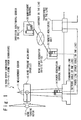
Fig. 1 is a diagram illustrating a configuration example of an operation monitoring system according to the present invention; -
Fig. 2 is a diagram for explaining details of the configuration example of the operation monitoring system according to the present invention; -
Fig. 3 is a diagram for explaining details of configuration examples of a remote monitoring apparatus and a management terminal according to the present invention; -
Fig. 4 is a diagram for explaining an implementation example of the operation monitoring system according to the present invention; and -
Fig. 5 is a flowchart for explaining the procedure of the process in the implementation example of the operation monitoring system according to the present invention. - In the following, a description is given of embodiments of the present invention with reference to the attached drawings. It should be noted that an operation monitoring system in the below-described embodiments of the present invention aims at realizing a SCADA (supervisory control and data acquisition) system.
- As illustrated in
Fig. 1 , an operation monitoring system in one embodiment of the present invention includes wind power generators 10 (10-i, where i = 1 to n, n being the number of the wind power generators), a remote monitoring unit (or a remote terminal unit (RTU)) 20, and a management terminal (or a human machine interface (HMI) 30. - The wind power generators 10 (10-i, where i = 1 to n) are disposed in a wind farm or the like and convert wind power energy into electric energy. It should be noted that the wind power generators 10 (10-i, where i = 1 to n) may be disposed in a mountain area or provided offshore, not limited to a flatland.
- The
remote monitoring unit 20 is disposed in a wind farm office or a wind turbine on-site office, near the wind power generators 10 (10-i, where i = 1 to n); theremote monitoring unit 20 monitors each of the wind power generators 10 (10-i, where i = 1 to n) located in the same site, which are to be monitored. - The
management terminal 30 is installed in an operation monitoring center or the like located away from the wind power generators 10 (10-i, where i = 1 to n) ; themanagement terminal 30 communicates with theremote monitoring units 20 via the internet or the like. Specifically, themanagement terminal 30 monitors the operational status of each of the wind power generators 10 (10-i, where i = 1 to n) via theremote monitoring unit 20 and provides control instructions and the like. It should be noted that themanagement terminal 30 can communicate with a plurality ofremote monitoring units 20 via the internet. - Each wind power generator 10 (10-i, where i = 1 to n) includes a measurement sensor(s) 11, a
wind turbine rotor 12, a wind turbine main unit (nacelle) 13 and a powergeneration control panel 14. - One or two
measurement sensors 11 are provided for each wind power generator. It should be noted that themeasurement sensors 11 are each required only to measure the status of the peripheral environment of the wind power generator; themeasurement sensors 11 may be each disposed near the wind power generator in an actual implementation. The measurement sensor (s) 11 measures the status of the peripheral environment of each wind power generator 10 (10-i, where i = 1 to n) and outputs the measurement result as the data related to the peripheral environment of each wind power generator 10 (10-i, where i = 1 to n). Examples of the status of the peripheral environment may include the wind conditions (the wind direction, wind speed or the like), the outside air temperature, and the like. It should be noted that an actual implementation is not limited to these examples. Also, when a trouble such as a failure occurs, the measurement sensor(s) 11 outputs data for notifying the occurrence of the trouble (a trouble notification). - The
wind turbine rotor 12 is rotated by the wind power, and the rotational motion is transmitted to the wind turbine main unit (or nacelle) 13. In other words, thewind turbine rotor 12 converts the wind power into rotational energy. - The wind turbine main unit (nacelle) 13 generates electricity on the rotational motion of the
wind turbine rotor 12. In other words, the wind turbine main unit (nacelle) 13 converts the rotational energy into electric energy. The wind turbine main unit (nacelle) 13 is disposed on the top of the tower of the wind power generator. In this embodiment, the wind turbine main unit (nacelle) 13 is understood as a head of the wind power generator. - The power
generation control panel 14 performs a basic operation control in the wind power generator to externally output data related to the generated electric power and the peripheral environment. The powergeneration control panel 14 is disposed at the root of the tower of the wind power generator. - Details of the configurations of the wind power generator 10 (10-i, where i = 1 to n), the
remote monitoring unit 20 and themanagement terminal 30 are described with reference toFigs. 2 and3 . - The
measurement sensor 11 includes an aerovane 111, an outsideair temperature gauge 112 and an inside temperature gauge 113. - The aerovane 111 measures the wind conditions (the wind direction, the wind speed and the like). The outside
air temperature gauge 112 measures the temperature of the outside air of the wind power generator. The inside temperature gauge 113 measures the inside temperature of the wind turbine main unit (nacelle) 13. - The
wind turbine rotor 12 includesblades 121, a hub (rotor) 122 and a pitchangle control system 123. - The
blades 121 correspond to the blades of thewind turbine rotor 12 and form a wind receiving face which receives the wind. The hub (rotor) 122 is rotated by the wind power received by the blades. Specifically, theblades 121 are pushed by the wind (the wind force or torque) and the hub (rotor) 122 is thereby rotated; the generator of the wind turbine main unit (nacelle) 13 connected to the hub (rotor) 122 is thereby rotated to generate electricity. Here, the following relation holds:
angle control system 123 changes the angle of the blades 121 (that is, performs a pitch control of the blades) in response to the rotational velocity of the hub (rotor) 122, and thereby adjusts the rotation of the hub (rotor) 122 to control the output. - The wind turbine main unit (nacelle) 13 includes a
gear box 131, a generator (turbine) 132 and ayaw control system 133. - The
gear box 131 transmits the rotation of thewind turbine rotor 12 to the generator (turbine) 132, converting the low-velocity rotation of the rotor into a high-velocity rotation. The generator (turbine) 132 generates electricity on the rotation transmitted from thegear box 131. Theyaw control system 133 performs a yaw control in accordance with the wind direction by rotating the wind turbine main unit (nacelle) 13, in order to direct thehub 122 towards the wind direction. - The power
generation control panel 14 includes apower supply section 141, a communication processing section 142 and aninternal control section 143. - The
power supply section 141 supplies (or transmits) electric power to a transformer or the like via a power line (power cable or the like). The communication processing section 142 communicates with theremote monitoring unit 20 via a communication line (a network cable or the like). Theinternal control section 143 controls internal entities of the wind power generator 10 (10-i, where i = 1 to n) (themeasurement sensor 11, thewind turbine rotor 12 and the wind turbine main unit (nacelle) 13). For example, theinternal control section 143 obtains data outputted from the measurement sensor 11 (various measurement results, a trouble notification and the like) and transmits the obtained data to theremote monitoring unit 20. Also, theinternal control section 143 may perform a process in response to a notification, instruction or request from theremote monitoring unit 20. Also, theinternal control section 143 performs the pitch control of theblades 121 of thewind turbine rotor 12 and the yaw control of the wind turbine main unit (nacelle) 13, in response to the measurement result of the aerovane 111. Also, theinternal control section 143 stops the rotation of the hub (rotor) 122 of thewind turbine rotor 12 in response to the measurement results of the outsideair temperature gauge 112 and the inside temperature 113. - The
remote monitoring unit 20 includes a peripheral environment data collection section 21, an operationstatus management section 22 and analarm issuing section 23. - The peripheral environment data collection section 21 collects data related to the peripheral environment of each of the wind power generators 10 (10-i, where i = 1 to n). Specifically, the peripheral environment data collection section 21 automatically collects on-line the data related to the peripheral environment outputted as a result of the measurement of the status of the peripheral environment by the
measurement sensor 11, for example. - The operation
status management section 22 performs a centralized management of the operation status of each of the wind power generators 10 (10-i, where i = 1 to n). The operationstatus management section 22 may accumulate data related to the operation status of each of the wind power generators 10 (10-i, where i = 1 to n). Also, the operationstatus management section 22 may issue a certain notification, instruction or request to each of the wind power generators 10 (10-i, where i = 1 to n) in response to changes in the data related to the peripheral environment and operation status of each of the wind power generators 10 (10-i, where i = 1 to n). It should be noted that, when thealarm issuing section 23 detects a failure of themeasurement sensor 11, the operationstatus management section 22 may automatically (or by a self-control) determine the wind power generator 10 (10-i, where i = 1 to n) in which the failure of themeasurement sensor 11 occurs, and transmit to that wind power generator 10 (10-i, where i = 1 to n) data related to the peripheral environment measured by ameasurement sensor 11 of a neighboring wind power generator 10 (10-i, where i = 1 to n). - The
alarm issuing section 23 issues an alarm for notifying an occurrence of a trouble, when detecting a trouble of themeasurement sensor 11. For example, when receiving a notification notifying a trouble from themeasurement sensor 11, receiving no notification of measurement result for a predetermined continuing period of time or finding abnormal data in the data related to the peripheral environment of each of the wind power generators 10 (10-i, where i = 1 to n), thealarm issuing section 23 determines that a failure occurs in themeasurement sensor 11. It is preferable that thealarm issuing section 23 is configured to, in addition to an alarm or as an alarm, output identification information (information for identifying the wind power generator of interest) of the wind power generator 10 (10-i, where i = 1 to n) for which the trouble occurs in themeasurement sensor 11 and/or identification information of themeasurement sensor 11 in order to allow identifying themeasurement sensor 11 in which a failure occurs. - The
management terminal 30 includes analarm detection section 31, aconsolidated control section 32 and anadministrator operation section 33. - The
alarm detection section 31 detects an alarm from theremote monitoring section 20 and notifies theconsolidated control section 32 of the detection of the alarm. In this embodiment, when detecting an alarm from theremote monitoring unit 20, thealarm detection section 31 extracts identification information of theremote monitoring unit 20 of the alarm-issuing source, the identification information of the wind power generator 10 (10-i, where i = 1 to n) for which the failure occurs in themeasurement sensor 11 and/or identification information of themeasurement sensor 11 to transmit to theconsolidated control section 32. - The
consolidated control section 32 controls the operation of each wind power generator 10 (10-i, where i = 1 to n) via theremote monitoring unit 20. For example, theconsolidated control section 32 transmits a notification, instruction or request to each wind power generator 10 (10-i, where i = 1 to n) via theremote monitoring unit 20. Theconsolidated control section 32 may control, via a plurality ofremote monitoring units 20, all the wind power generators 10 (10-i, where i = 1 to n) monitored by the respectiveremote monitoring units 20. Also, theconsolidated control section 32 recognizes the wind power generator 10 (10-i, where i = 1 to n) for which a trouble occurs in themeasurement sensor 11, on the basis of the notification of the alarm detection from the alarm detection section31. In this case, theconsolidated control section 32 may instruct or request theremote monitoring unit 20 of the source of the alarm to transmit data related to the peripheral environment measured by ameasurement sensor 11 of a neighboring wind power generator 10 (10-i, where i = 1 to n) to the wind power generator 10 (10-i, where i = 1 to n) for which the failure occurs in themeasurement sensor 11. Also, theconsolidated control section 32 may notify theadministrator operation section 33 of the identification information of themeasurement sensor 11 in which the failure occurs. When an immediate replacement or repair (maintenance) of themeasurement sensor 11 is difficult, theadministrator operation section 33 calculates the time when the replacement or repair of themeasurement sensor 11 is made possible and notifies theadministrator operation section 33 of the time. Alternatively, theadministrator operation section 33 may be notified of the identification information of themeasurement sensor 11 in which the failure occurs and of the fact that themeasurement sensor 11 is to be replaced or repaired at that time. - The
administrator operation section 33 notifies the administrator (or the operator) of various information, including data related to the operation status and the peripheral environment of each wind power generator 10 (10-i, where i = 1 to n) and the like, handles an operation by the administrator, generates or update setting information related to the control done by theconsolidated control section 32 and transmits a notification, instruction or request to each wind power generator 10 (10-i, where i = 1 to n) via theremote monitoring unit 20. - In the following, a description is given of specific examples of hardware of the respective components of the operation monitoring system according to the present embodiment.
- An assumed example of the respective wind power generators 10 (10-i, where i = 1 to n) include a wind power generator in which a wind turbine and a wind power generator are combined as a unit. Note that a possible example of a wind power generator 10 (10-i, where i = 1 to n) which does not use a wind turbine is a generator which receives the wind on a diaphragm and obtains electric power by a piezoelectric element.
- Assumed examples of the
measurement sensor 11 include peripheral environment sensors such as aerovanes and outside air temperature gauges. Themeasurement sensor 11 may have the timer function or the GPS (global positioning system) function to obtain the time (the time slot, the date, the day of the week, the season), the latitude, longitude, orientation of the sensor and environment information such as the amount of insolation (the light intensity, the amount of light), the air pressure, the humidity, the magnitude of sound, the sound pressure, the electric field intensity (strength of electric wave), the power consumption, the existence of a neighboring shielding structure, the earthquake intensity, the earth magnetism, the electric wave, the radiation ray, the concentration in the atmosphere (COx, NOx or the like). - An assumed example of the
wind turbine rotor 12 is a horizontal-axis propeller type turbine. Other examples of thewind turbine rotor 12 may include a horizontal-axis multi-blade-type wind turbine, a horizontal-axis sail wing type wind turbine, a vertical-axis Darius type wind turbine, a gyromill type wind turbine, a Savonius type wind turbine and a combination thereof, a straight-blade vertical axis wind turbine and a screw Magnus wind turbine (which uses the Magnus effect). - Assumed examples of the
remote monitoring unit 20 and themanagement terminal 30 include computers such as PCs (personal computers), appliances, workstations, main frames, and super computers. Note that portable terminals such as cell phones, smart phones and smart books should be also understood as a sort of computers. - Although not shown, the above-described computers are realized by a processor operated on programs to perform predetermined processes, a memory storing the programs and various data and an interface used for communications over a network.
- Examples of the above-described processor include: CPUs (central processing units), network processors (NPs), microprocessors, micro controllers, and dedicated semiconductor integrated circuits (IC).
- Examples of the above-described memory include semiconductor memory devices such as RAMs (random access memories), ROMs (read only memories), EEPROM (electrically erasable and programmable read only memories) and flash memories, auxiliary memory units such as HDDs (hard disk drives) and SSDs (solid state drives), removable disks such as DVDs (digital versatile disks), and memory media such as SD (secure digital) memory card. Also, the above-described memory may be a buffer or a register. Alternatively, the above-described memory may be a storage device using a DAS (direct attached storage), an FC-SAN (fiber channel-storage area network), an NAS (network attached storage), an IP-SAN (IP-storage area network) or the like.
- Note that the above-described processor and the above-described memory may be monolithically integrated. Recent microcomputers and the like increasingly tend to be formed as one-chip devices. Accordingly, in an assumed implementation, a one-chip microcomputer installed in an electronic device or the like may incorporate the above-described processor and the above-described memory.
- Examples of the above-described interfaces include circuit boards (mother boards and I/O boards) adapted to network communications, semiconductor integrated circuits such as chips, network adapters such as NICs (network interface cards), similar expansion cards, communication devices such as antennas, and communication ports such as connectors.
- Examples of the network include the internet, LANs (local area networks), wireless LANs, WANs (wide area networks), backbones, cable television (CATV) lines, fixed phone networks, public telephone networks, cell phone networks, WiMAX (IEEE 802.16a), 3G (3rd generation), lease lines, IrDA (infrared data association), Bluetooth (registered trade mark), serial communication lines and data buses.
- It should be noted the respective sections (internal entities) in the
remote monitor unit 20 and themanagement terminal 30 may be modules, components, dedicated devices or starting (calling) programs of the same. Alternatively, the respective sections (internal entities) in theremote monitor unit 20 and themanagement terminal 30 may be independent computers. - The
remote monitoring unit 20 and themanagement terminal 30 are not limited to terminals or servers; theremote monitoring unit 20 and themanagement terminal 30 may be an intermediary device or a peripheral device. Alternatively, theremote monitoring unit 20 and themanagement terminal 30 may be an add-in board mounted on a computer or a virtual machine (VM) built on a physical machine. Theremote monitoring unit 20 and themanagement terminal 30 may be mounted on a moving body such as a vehicle, a ship and an airplane. - Assumed examples of the
administrator operation section 33 include a KVM (keyboard video mouse), a console, a keypad, a touch panel, a tablet, a reading device of various data transmission media, a display device such as LCD (liquid crystal display), a PDP (plasma display panel), an organic EL (electroluminescence) display, and an interface for communicating with external computers or interface devices. - It should be noted that actual implementations are not limited to these examples.
- Referring to
Figs. 4 and5 , a description is given of a specific example of the present invention. - In this example, as shown in
Fig. 4 , examples of the wind power generators 10 (10-i, where i = 1 to n) include wind power generators 10-1, 10-2 and 10-3. - The wind power generators 10-1, 10-2 and 10-3 are located in the same site. The
remote monitoring unit 20 monitors the wind power generators 10-1, 10-2 and 10-3 and comprehends or recognizes on the basis of preliminary settings or the like that the wind power generators 10-1, 10-2 and 10-3 are located close to each other (in the same site). - Referring to
Fig. 5 , a description is given below of the procedure of the process in this example. - Each of the wind power generators 10-1, 10-2 and 10-3 measures the status of the peripheral environment related to the wind conditions (the wind direction, the wind speed and the like) and the outside air temperature, by using the
measurement sensors 11. - The
remote monitoring unit 20 collects data related to the peripheral environment obtained by themeasurement sensor 11 of each of the respective wind power generators 10-1, 10-2 and 10-3. In an actual implementation, theremote monitoring unit 20 may periodically read the data related to the peripheral environments obtained by therespective measurement sensors 11 from the wind power generators 10-1, 10-2 and 10-3. Alternatively, each of the wind power generators 10-1, 10-2 and 10-3 may periodically notify or transmit the data related to the peripheral environment obtained by itsown measurement sensor 11 to theremote monitoring unit 20. - Here, let us consider the case when a failure occurs in the
measurement sensor 11 of the wind power generator 10-2. That is, let us consider the case when a trouble occurs in themeasurement sensor 11 of the wind power generator 10-2. - The
remote monitoring device 20 detects the occurrence of the trouble in themeasurement sensor 11 of the wind power generator 10-2. - The
remote monitoring unit 20 determines to transmit data related to the peripheral environment obtained by ameasurement sensor 11 of a neighboring wind power generator of the wind power generator 10-2 (that is, the wind power generator 10-1 or 10-3), to the wind power generator 10-2. As the neighboring wind power generator, any predetermined one of other wind power generators in the same site is selected. For example, a wind power generator disposed near the wind power generator 10-2 in which the failure occurs is selected. - In this operation, the
remote monitoring unit 20 may automatically determine to transmit to the wind power generator 10-2 the data related to the peripheral environment obtained by themeasurement sensor 11 of the neighboring wind power generator of the wind power generator 10-2 (the wind power generator 10-1 or 10-3). - Alternatively, the
remote monitoring unit 20 may notify themanagement terminal 30 of the occurrence of the trouble of themeasurement sensor 11 of the wind power generator 10-2 and determine to transmit to the wind power generator 10-2 the data related to the peripheral environment obtained by themeasurement sensor 11 of the neighboring wind power generator of the wind power generator 10-2 (the wind power generator 10-1 or 10-3), under the control from themanagement terminal 30. - The
remote monitoring unit 20 transmits the data related to the peripheral environment obtained by themeasurement sensor 11 of a different wind power generator other than the wind power generator 10-2 (the wind power generator 10-1 or 10-3) to the wind power generator 10-2. The selection of the different wind power generator is achieved as follows: For each wind power generator, a wind turbine generator around (or near) the each wind power generator is defined as the neighboring wind power generator. Theremote monitoring unit 20 stores a neighboring wind power generator table indicative of an association of each wind power generator with the neighboring wind turbine generator in a storage device in advance. At step S106, theremote monitoring unit 20 extracts the associated neighboring wind power generator from the table, for the wind turbine generator 10-2 in which the trouble occurs in themeasurement sensor 11. The measured values obtained by themeasurement sensor 11 of the extracted neighboring wind power generator are determined as alternative data used in case of the trouble. Theremote monitoring unit 20 transmits the alternative data to the wind power generator 10-2. This allows the wind power generator 10-2 to continue the operation by using the alternative data. - In an actual implementation, the
remote monitoring unit 20 may calculate the average values of the data related to the peripheral environment obtained by therespective measurement sensors 11 of a plurality of wind power generators (the wind power generators 10-1 and 10-3) and transmit the average values to the wind power generator 10-2. In this case, the process of calculating the average values is performed as follows, for example: At least one neighboring wind power generator is memorized for each wind power generator in the neighboring wind power generator table. At step S106, when two or more neighboring wind power generators are memorized in the neighboring wind power generator table for the wind power generator 10-2, in which the trouble occurs in themeasurement sensor 11, theremote monitoring unit 20 calculates the average values of the measured values obtained by themeasurement sensors 11 of the neighboring wind power generators. The average values are determined as the data related to the peripheral environment, which are to be transmitted to the wind power generator 10-2. - The wind power generator 10-2 uses the data related to the peripheral environment transmitted from the
remote monitoring unit 20 in place of the data related to the peripheral environment obtained by itsown measurement sensor 11 to control the rotation of its ownwind turbine rotor 12. - Let us consider the case when a trouble occurs in the outside air temperature gauge 112 (a means for obtaining data related to the outside air temperature) of the
measurement sensor 11 in the wind power generator 10-2. In this case, theremote monitoring unit 20 transmits the data related to the outside air temperature of themeasurement sensor 11 of at least one other wind power generator, as alternative data. The wind power generator 10-2 monitors the normality of the internal temperature of thenacelle 13, on the basis of the alternative data of the outside air temperature and data related to the inside temperature measured by the inside temperature gauge 113 of itsown measurement sensor 11. When the outside air temperature (accurately, the value of the alternative data) and the inside temperature satisfy a predetermined standard, the wind power generator 10-2 can continue the operation even when a trouble occurs in the outsideair temperature gauge 112 of itsown measurement sensor 11. - Originally, a measurement sensor can be replaced without stopping the wind power generator even when a trouble such as a failure occurs; however, since the replacement makes it impossible to measure the wind conditions (the wind direction, the wind speed and the like), the outside air temperature and the like, the operation of the wind power generator is conventionally stopped undesirably.
- For example, the operation of the wind power generator is conventionally stopped when a failure occurs in the aerovane, since the wind receiving face of the wind turbine cannot be rotated in accordance with the wind direction (for an upwind type wind turbine, toward the upwind direction) due to the impossibility of the measurement of the wind direction and speed.
- Also, the operation of the wind power generator is conventionally stopped when a failure occurs in the outside air temperature gauge, since the temperature abnormality which occurs in the wind turbine main unit (nacelle) cannot be monitored on the basis of the difference between the outside air temperature and the inside temperature of the wind turbine main unit (nacelle).
- In some of the above-described embodiments of the present invention, on the contrary, the wind power generator can continue to operate without stopping, until a replacement or repair is completed after the failure occurs in the measurement sensor, by receiving data related to the peripheral environment of a neighboring wind power generator (located in the same site) and using the received data as the data related to its own peripheral environment.
- As described above, in an operation monitoring system according to some embodiments of the present invention, the measurement sensor mounted on each of the wind power generators located in the same site measures the status of the peripheral environment of each wind power generator. The remote monitoring unit monitors the respective wind power generators and collects data related to the operation statuses and peripheral environments of the respective wind power generators. When detecting an occurrence of a trouble in the measurement sensor of a certain wind power generator of the respective wind power generators, the remote monitoring unit transmits data related to the peripheral environment measured by the measurement sensor of a different wind power generator located near the certain wind power generator, to the certain wind power generator, in which the trouble occurs in the measurement sensor. Each wind power generator continues to operate by using data related to the peripheral environment transmitted from the remote monitoring unit, even when a trouble occurs in the measurement sensor.
- This allows safely operating the wind power generator without stopping the wind turbine, even when a failure occurs in the measurement sensor, such as an aerovane; this avoids the loss of power generation until the replacement or repair is completed.
- Although embodiments of the present invention are described in detail in the above, the present invention is not limited to the above-described embodiments in actual implementations; the present invention encompasses modifications which do not depart from the concept of the present invention. For example, combinations of the above-described embodiments may be also embodiments of the present invention as long as no inconsistency occurs.
- The present application claims priority based on Japanese Patent Application No.
2011-143332, filed on June 28, 2011
Claims (11)
- An operation monitoring system, comprising:a plurality of wind power generators located in a same site, each measuring a status of a peripheral environment by a measurement sensor; anda remote monitoring unit monitoring each of said plurality of wind power generators to collect data related to the peripheral environment of each wind power generator,wherein, when detecting an occurrence of a trouble in the measurement sensor of at least one wind power generator out of said plurality of wind power generators, said remote monitoring unit transmits data related to the peripheral environment measured by the measurement sensor of a different wind power generator other than the wind turbine generator for which the trouble occurs in said measurement sensor out of said plurality of wind turbine generators, to the wind turbine generator for which the trouble occurs in said measurement sensor, andwherein the wind power generator for which the trouble occurs in said measurement sensor continues to operate by using the data related to the peripheral environment which are transmitted from said remote monitoring unit.
- The operation monitoring system according to claim 1, wherein said measurement sensor includes means for measuring a wind direction and speed, and
wherein each of said plurality of wind power generators includes:means for, when the trouble occurs in said measurement sensor, obtaining data related to the wind direction and speed measured by the measurement sensor of said different wind power generator from said remote monitoring unit; andmeans for performing a control of a pitch angle of blades of a wind turbine rotor and a yaw control of a nacelle, based on said obtained data related to the wind direction and speed. - The operation monitoring system according to claim 1 or 2, wherein said measurement sensor includes means for measuring an outside air temperature,
wherein each of said plurality of wind power generators includes:means for, when the trouble occurs in said measurement sensor, obtaining data related to the outside air temperature measured by the measurement sensor of said different wind power generator from said remote monitoring unit; andmeans for, in response to said obtained data related to the outside air temperature, based on a difference between the outside air temperature and an inside temperature of a nacelle, monitoring abnormality of the inside temperature of said nacelle to continue an operation of a wind turbine. - The operation monitoring system according to any one of claims 1 to 3, wherein said remote monitoring unit includes:means for calculating an average value of data related to peripheral environments of two or more wind power generators located near the wind power generator for which the trouble occurs in said measurement sensor; andmeans for transmitting data based on said calculated average value as said data related to the peripheral environment, to the wind power generator for which the trouble occurs in said measurement sensor.
- A remote monitoring unit, comprising:means for collecting, from a plurality of wind power generators located in a same site, data measured by a measurement sensor for measuring data related to a peripheral environment of each of the wind power generators;means for detecting an occurrence of a trouble of a measurement sensor of at least one wind power generator out of said plurality of wind power generators; andmeans for transmitting data related to the peripheral environment measured by the measurement sensor of a different wind power generator other than the wind turbine generator for which the trouble occurs in said measurement sensor out of said plurality of wind turbine generators, to the wind turbine generator for which the trouble occurs in said measurement sensor.
- The remote monitoring unit according to claim 5, further comprising:means for calculating an average value of data related to peripheral environments measured by measurement sensors of multiple wind power generators located near the wind power generator for which the trouble occurs in said measurement sensor; andmeans for transmitting data based on said calculated average value as said data related to the peripheral environment, to the wind power generator for which the trouble occurs in said measurement sensor.
- A wind power generator, comprising:means for measuring a status of a peripheral environment by using a measurement sensor provided;means for, when a trouble occurs in said measurement sensor, obtaining data related to a peripheral environment measured by a measurement sensor of a different wind power generator from a remote monitoring unit which monitors each of a plurality of wind power generators located in a same site as the wind power generator to collect data related to a peripheral environment of each of said plurality of wind power generators; andmeans for continuing an operation by using the data related to the peripheral environment obtained from said remote monitoring unit.
- The wind power generator according to claim 7, further comprising:means for measuring a wind direction and speed by using said measurement sensor;means for, when the trouble occurs in said measurement sensor, obtaining data related to a wind direction and speed measured by a measurement sensor of a different wind power generator located near the wind power generator from said remote monitoring unit; andmeans for performing a control of a pitch angle of blades of a wind turbine rotor and a yaw control of a nacelle, based on said obtained data related to the wind direction and speed.
- The wind power generator according to claim 7 or 8, further comprising:means for measuring an outside air temperature by using said measurement sensor;means for, when the trouble occurs in said measurement sensor, obtaining data related to an outside air temperature measured by a measurement sensor of a different wind power generator located near the wind power generator from said remote monitoring unit; andmeans for, in response to said obtained data related to the outside air temperature, based on a difference between the outside air temperature and an inside temperature of a nacelle, monitoring abnormality of the inside temperature of said nacelle to continue an operation of a wind turbine.
- An operation monitoring method, comprising:a step of, by a measurement sensor mounted on each of a plurality of wind turbine generators located in a same site, measuring a status of a peripheral environment of each of said plurality of wind turbine generators;a step of, by a remote monitoring unit, monitoring each of said plurality of wind power generators to collect data related to the peripheral environment of each of said plurality of wind power generator;a step of, when said remote monitoring unit detects a occurrence of a trouble in the measurement sensor of at least one wind power generator out of said plurality of wind power generators, transmitting data related to the peripheral environment measured by the measurement sensor of a different wind power generator other than the wind turbine generator for which the trouble occurs in said measurement sensor out of said plurality of wind turbine generators, to the wind turbine generator for which the trouble occurs in said measurement sensor; anda step of continuing an operate of the wind power generator for which the trouble occurs in said measurement sensor by using the data related to the peripheral environment which are transmitted from said remote monitoring unit.
- A program for causing a remote monitoring unit to perform steps of:collecting, from a plurality of wind power generators located in a same site, data measured by a measurement sensor for measuring data related to a peripheral environment of each of the wind power generators; andwhen a occurrence of a trouble is detected in the measurement sensor of at least one wind power generator out of said plurality of wind power generators, transmitting data related to a peripheral environment measured by a measurement sensor of a different wind power generator other than the wind turbine generator for which the trouble occurs in said measurement sensor out of said plurality of wind turbine generators, to the wind turbine generator for which the trouble occurs in said measurement sensor.
Applications Claiming Priority (2)
| Application Number | Priority Date | Filing Date | Title |
|---|---|---|---|
| JP2011143332A JP2013011200A (en) | 2011-06-28 | 2011-06-28 | Operation monitoring system, operation monitoring method, and program |
| PCT/JP2012/066374 WO2013002256A1 (en) | 2011-06-28 | 2012-06-27 | Operation monitoring system, operation monitoring method, and program |
Publications (2)
| Publication Number | Publication Date |
|---|---|
| EP2728175A1 true EP2728175A1 (en) | 2014-05-07 |
| EP2728175A4 EP2728175A4 (en) | 2015-03-25 |
Family
ID=47424147
Family Applications (1)
| Application Number | Title | Priority Date | Filing Date |
|---|---|---|---|
| EP12803930.2A Withdrawn EP2728175A4 (en) | 2011-06-28 | 2012-06-27 | Operation monitoring system, operation monitoring method, and program |
Country Status (3)
| Country | Link |
|---|---|
| EP (1) | EP2728175A4 (en) |
| JP (1) | JP2013011200A (en) |
| WO (1) | WO2013002256A1 (en) |
Cited By (8)
| Publication number | Priority date | Publication date | Assignee | Title |
|---|---|---|---|---|
| CN104963928A (en) * | 2015-07-22 | 2015-10-07 | 李圣用 | System for reducing wind driven generator bolt scheduled maintenance frequency |
| WO2016050249A1 (en) * | 2014-09-29 | 2016-04-07 | Vestas Wind Systems A/S | Verification of wind turbine nacelle yaw position sensor |
| EP3176427A4 (en) * | 2014-07-29 | 2018-03-14 | NTN Corporation | State monitoring system and wind power generation system provided with same |
| CN108754503A (en) * | 2018-06-29 | 2018-11-06 | 中交第三航务工程局有限公司 | A kind of monitoring system of offshore wind power foundation |
| US10487801B2 (en) | 2015-03-02 | 2019-11-26 | Wobben Properties Gmbh | Method for operating a wind turbine |
| US10519935B2 (en) | 2014-06-24 | 2019-12-31 | Ntn Corporation | Condition monitoring system and wind power generation system using the same |
| US11262732B2 (en) | 2017-03-31 | 2022-03-01 | Mitsubishi Heavy Industries, Ltd. | Plant monitoring system, plant operation assistance system, plant monitoring method, and program |
| WO2022110330A1 (en) * | 2020-11-26 | 2022-06-02 | 中车永济电机有限公司 | Wind turbine fault detection method, data acquisition device, server, and system |
Families Citing this family (16)
| Publication number | Priority date | Publication date | Assignee | Title |
|---|---|---|---|---|
| KR101466082B1 (en) | 2013-06-07 | 2014-11-27 | 삼성중공업 주식회사 | Method of controlling wind power generator |
| CN103809556A (en) * | 2013-12-12 | 2014-05-21 | 神华集团有限责任公司 | Fan state monitoring system and method |
| CN103728942A (en) * | 2013-12-24 | 2014-04-16 | 青海能高新能源有限公司 | Local data collecting and processing system of wind generating set |
| CN103742358B (en) * | 2013-12-24 | 2016-06-15 | 青海能高新能源有限公司 | A kind of Combined type wind driven generator group condition monitoring system |
| KR101458786B1 (en) * | 2014-02-20 | 2014-11-07 | 두산중공업 주식회사 | a wind farm, an arranging structure thereof and a control method thereof, a wind generator unit |
| JP6247957B2 (en) * | 2014-02-26 | 2017-12-13 | 三菱重工業株式会社 | Yaw control system and yaw control method for wind turbine generator |
| WO2016138647A1 (en) * | 2015-03-04 | 2016-09-09 | General Electric Company | System and method for mitigating loads on a wind turbine |
| JPWO2017199427A1 (en) * | 2016-05-20 | 2018-10-18 | 三菱電機株式会社 | Equipment monitoring device, wireless sensor, and collection station |
| JP2018097733A (en) * | 2016-12-15 | 2018-06-21 | 株式会社日立製作所 | Operation support system and operation support method |
| US10598148B2 (en) * | 2017-08-22 | 2020-03-24 | General Electric Company | System for controlling a yaw drive of a wind turbine when a native yaw drive control system is non-operational |
| CN110578659B (en) * | 2018-06-07 | 2021-12-03 | 华北电力大学 | System and method for processing SCADA data of wind turbine generator |
| CN111145109B (en) * | 2019-12-09 | 2023-03-31 | 深圳先进技术研究院 | Wind power generation power curve abnormal data identification and cleaning method based on image |
| JP7657025B2 (en) * | 2020-02-21 | 2025-04-04 | 株式会社東光高岳 | Lightning strike information providing method and lightning strike information providing server |
| CN112628088A (en) * | 2020-05-29 | 2021-04-09 | 厦门领航互联信息技术有限公司 | Online real-time monitoring system for rotating speed of wind power generation blade |
| CN113984111A (en) * | 2021-09-30 | 2022-01-28 | 北京华能新锐控制技术有限公司 | Wind turbine control method and device based on external environment changes |
| CN114852310A (en) * | 2022-07-05 | 2022-08-05 | 南通格霖海事工程有限公司 | Rotary air duct for ship |
Family Cites Families (5)
| Publication number | Priority date | Publication date | Assignee | Title |
|---|---|---|---|---|
| US20020029097A1 (en) | 2000-04-07 | 2002-03-07 | Pionzio Dino J. | Wind farm control system |
| JP2007285214A (en) * | 2006-04-18 | 2007-11-01 | Nabtesco Corp | Windmill control device |
| US7677075B2 (en) * | 2006-09-29 | 2010-03-16 | General Electric Company | Methods and apparatus for evaluating sensors and/or for controlling operation of an apparatus that includes a sensor |
| JP4698718B2 (en) * | 2008-09-30 | 2011-06-08 | 株式会社日立製作所 | Wind turbine generator group control device and control method |
| US8112252B2 (en) * | 2010-10-29 | 2012-02-07 | General Electric Company | Control system and methods of verifying operation of at least one wind turbine sensor |
-
2011
- 2011-06-28 JP JP2011143332A patent/JP2013011200A/en active Pending
-
2012
- 2012-06-27 WO PCT/JP2012/066374 patent/WO2013002256A1/en not_active Ceased
- 2012-06-27 EP EP12803930.2A patent/EP2728175A4/en not_active Withdrawn
Cited By (12)
| Publication number | Priority date | Publication date | Assignee | Title |
|---|---|---|---|---|
| US10519935B2 (en) | 2014-06-24 | 2019-12-31 | Ntn Corporation | Condition monitoring system and wind power generation system using the same |
| EP3176427A4 (en) * | 2014-07-29 | 2018-03-14 | NTN Corporation | State monitoring system and wind power generation system provided with same |
| US10047726B2 (en) | 2014-07-29 | 2018-08-14 | Ntn Corporation | Condition monitoring system and wind power generation system comprising the same |
| WO2016050249A1 (en) * | 2014-09-29 | 2016-04-07 | Vestas Wind Systems A/S | Verification of wind turbine nacelle yaw position sensor |
| CN106922162A (en) * | 2014-09-29 | 2017-07-04 | 维斯塔斯风力系统有限公司 | The checking of Wind turbine nacelle yaw attitude sensor |
| EP3201465B1 (en) | 2014-09-29 | 2018-11-07 | Vestas Wind Systems A/S | Verification of wind turbine nacelle yaw position sensor and yaw control system |
| US10557459B2 (en) | 2014-09-29 | 2020-02-11 | Vestas Wind Systems A/S | Verification of wind turbine nacelle yaw position sensor |
| US10487801B2 (en) | 2015-03-02 | 2019-11-26 | Wobben Properties Gmbh | Method for operating a wind turbine |
| CN104963928A (en) * | 2015-07-22 | 2015-10-07 | 李圣用 | System for reducing wind driven generator bolt scheduled maintenance frequency |
| US11262732B2 (en) | 2017-03-31 | 2022-03-01 | Mitsubishi Heavy Industries, Ltd. | Plant monitoring system, plant operation assistance system, plant monitoring method, and program |
| CN108754503A (en) * | 2018-06-29 | 2018-11-06 | 中交第三航务工程局有限公司 | A kind of monitoring system of offshore wind power foundation |
| WO2022110330A1 (en) * | 2020-11-26 | 2022-06-02 | 中车永济电机有限公司 | Wind turbine fault detection method, data acquisition device, server, and system |
Also Published As
| Publication number | Publication date |
|---|---|
| WO2013002256A1 (en) | 2013-01-03 |
| JP2013011200A (en) | 2013-01-17 |
| EP2728175A4 (en) | 2015-03-25 |
Similar Documents
| Publication | Publication Date | Title |
|---|---|---|
| WO2013002256A1 (en) | Operation monitoring system, operation monitoring method, and program | |
| CA2858702C (en) | Methods and systems for detecting wind turbine rotor blade damage | |
| DK2599995T3 (en) | Wind turbine control system | |
| EP1959134B1 (en) | Method and system for utilizing lateral tower acceleration to detect asymmetric icing | |
| EP2199606B1 (en) | Method for determining a potential for icing on a wind turbine blade | |
| CN101598110B (en) | System and method for trip event data acquisition and wind turbine incorporating same | |
| ES2426128T3 (en) | Systems and procedures to test a wind turbine pitch control system | |
| CN111472943A (en) | Distributed measurement system and method with high synchronization precision for wind turbine generator | |
| US10557459B2 (en) | Verification of wind turbine nacelle yaw position sensor | |
| DK1936186T3 (en) | The wind turbine and method of detecting asymmetric icing on a wind turbine | |
| EP3511567A1 (en) | State monitoring device for wind power generating device, state monitoring system including same, and state monitoring method for wind power generating device | |
| US20120029843A1 (en) | Method, system, and computer program product for sensor data collection in a wind turbine | |
| WO2017195698A1 (en) | Electric power generation facility monitoring system, electric power generation facility monitoring method, and program | |
| CN113811686B (en) | Relative rotor blade misalignment | |
| CN103266986A (en) | Method and device for debugging variable-pitch system of wind generating set | |
| CN210033718U (en) | Signal acquisition and control system for wind driven generator model test | |
| CN116624331B (en) | Intelligent Redundant Group Control Method, Device, Storage Medium and Terminal Equipment for Wind Turbine Units | |
| KR101314716B1 (en) | Wind turbine check system based app. | |
| KR20170029879A (en) | System for monitoring wind turbine | |
| CN212615177U (en) | A distributed measurement system with high synchronization accuracy for wind turbines | |
| KR20210081574A (en) | Development of Facility Status Inspection and operation System for ESS Accident Prevention and Facility Safety | |
| CN113294299B (en) | Wind power blade monitoring method and related equipment | |
| CN204030720U (en) | A kind of fan condition statistical system device | |
| KR20170029880A (en) | System and method for controlling wind turbine having multi-sensor | |
| KR20240079936A (en) | An apparatus and method for detecting abnormality of a wind generator, and a system therefor |
Legal Events
| Date | Code | Title | Description |
|---|---|---|---|
| PUAI | Public reference made under article 153(3) epc to a published international application that has entered the european phase |
Free format text: ORIGINAL CODE: 0009012 |
|
| 17P | Request for examination filed |
Effective date: 20131127 |
|
| AK | Designated contracting states |
Kind code of ref document: A1 Designated state(s): AL AT BE BG CH CY CZ DE DK EE ES FI FR GB GR HR HU IE IS IT LI LT LU LV MC MK MT NL NO PL PT RO RS SE SI SK SM TR |
|
| DAX | Request for extension of the european patent (deleted) | ||
| A4 | Supplementary search report drawn up and despatched |
Effective date: 20150219 |
|
| RIC1 | Information provided on ipc code assigned before grant |
Ipc: F03D 11/00 20060101ALI20150213BHEP Ipc: F03D 7/04 20060101AFI20150213BHEP |
|
| STAA | Information on the status of an ep patent application or granted ep patent |
Free format text: STATUS: THE APPLICATION HAS BEEN WITHDRAWN |
|
| 18W | Application withdrawn |
Effective date: 20150605 |