EP2728022A1 - Methods and systems for reducing metal oxides - Google Patents
Methods and systems for reducing metal oxides Download PDFInfo
- Publication number
- EP2728022A1 EP2728022A1 EP12007520.5A EP12007520A EP2728022A1 EP 2728022 A1 EP2728022 A1 EP 2728022A1 EP 12007520 A EP12007520 A EP 12007520A EP 2728022 A1 EP2728022 A1 EP 2728022A1
- Authority
- EP
- European Patent Office
- Prior art keywords
- reaction
- oxide particles
- aluminum
- metal
- reactor
- Prior art date
- Legal status (The legal status is an assumption and is not a legal conclusion. Google has not performed a legal analysis and makes no representation as to the accuracy of the status listed.)
- Withdrawn
Links
- 238000000034 method Methods 0.000 title claims abstract description 71
- 229910044991 metal oxide Inorganic materials 0.000 title claims abstract description 54
- 150000004706 metal oxides Chemical class 0.000 title claims abstract description 54
- 229910052751 metal Inorganic materials 0.000 claims abstract description 39
- 239000002184 metal Substances 0.000 claims abstract description 39
- QVGXLLKOCUKJST-UHFFFAOYSA-N atomic oxygen Chemical compound [O] QVGXLLKOCUKJST-UHFFFAOYSA-N 0.000 claims abstract description 32
- 229910052760 oxygen Inorganic materials 0.000 claims abstract description 32
- 239000001301 oxygen Substances 0.000 claims abstract description 32
- 239000007789 gas Substances 0.000 claims abstract description 28
- 238000004519 manufacturing process Methods 0.000 claims abstract description 27
- 230000002829 reductive effect Effects 0.000 claims abstract description 22
- QGZKDVFQNNGYKY-UHFFFAOYSA-N Ammonia Chemical compound N QGZKDVFQNNGYKY-UHFFFAOYSA-N 0.000 claims abstract description 18
- 239000001257 hydrogen Substances 0.000 claims abstract description 13
- 229910052739 hydrogen Inorganic materials 0.000 claims abstract description 13
- 150000002739 metals Chemical class 0.000 claims abstract description 12
- UFHFLCQGNIYNRP-UHFFFAOYSA-N Hydrogen Chemical compound [H][H] UFHFLCQGNIYNRP-UHFFFAOYSA-N 0.000 claims abstract description 11
- UGFAIRIUMAVXCW-UHFFFAOYSA-N Carbon monoxide Chemical compound [O+]#[C-] UGFAIRIUMAVXCW-UHFFFAOYSA-N 0.000 claims abstract description 10
- 229910002091 carbon monoxide Inorganic materials 0.000 claims abstract description 10
- 229910021529 ammonia Inorganic materials 0.000 claims abstract description 8
- 239000000446 fuel Substances 0.000 claims abstract description 6
- 229930195733 hydrocarbon Natural products 0.000 claims abstract description 6
- 150000002430 hydrocarbons Chemical class 0.000 claims abstract description 6
- 238000006243 chemical reaction Methods 0.000 claims description 73
- XLOMVQKBTHCTTD-UHFFFAOYSA-N Zinc monoxide Chemical compound [Zn]=O XLOMVQKBTHCTTD-UHFFFAOYSA-N 0.000 claims description 61
- 239000000047 product Substances 0.000 claims description 46
- 238000006722 reduction reaction Methods 0.000 claims description 36
- 239000002245 particle Substances 0.000 claims description 31
- 239000011787 zinc oxide Substances 0.000 claims description 30
- 239000003638 chemical reducing agent Substances 0.000 claims description 28
- 239000011701 zinc Substances 0.000 claims description 28
- OKTJSMMVPCPJKN-UHFFFAOYSA-N Carbon Chemical group [C] OKTJSMMVPCPJKN-UHFFFAOYSA-N 0.000 claims description 25
- 238000010791 quenching Methods 0.000 claims description 25
- VNWKTOKETHGBQD-UHFFFAOYSA-N methane Chemical compound C VNWKTOKETHGBQD-UHFFFAOYSA-N 0.000 claims description 20
- 239000000463 material Substances 0.000 claims description 19
- 229910002804 graphite Inorganic materials 0.000 claims description 18
- 239000010439 graphite Substances 0.000 claims description 18
- 230000000171 quenching effect Effects 0.000 claims description 18
- 239000007787 solid Substances 0.000 claims description 18
- 239000007858 starting material Substances 0.000 claims description 17
- 239000011261 inert gas Substances 0.000 claims description 16
- VYPSYNLAJGMNEJ-UHFFFAOYSA-N silicon dioxide Inorganic materials O=[Si]=O VYPSYNLAJGMNEJ-UHFFFAOYSA-N 0.000 claims description 16
- IJGRMHOSHXDMSA-UHFFFAOYSA-N Atomic nitrogen Chemical compound N#N IJGRMHOSHXDMSA-UHFFFAOYSA-N 0.000 claims description 15
- 229910052782 aluminium Inorganic materials 0.000 claims description 15
- PNEYBMLMFCGWSK-UHFFFAOYSA-N aluminium oxide Inorganic materials [O-2].[O-2].[O-2].[Al+3].[Al+3] PNEYBMLMFCGWSK-UHFFFAOYSA-N 0.000 claims description 15
- 239000000203 mixture Substances 0.000 claims description 15
- 239000010453 quartz Substances 0.000 claims description 15
- XAGFODPZIPBFFR-UHFFFAOYSA-N aluminium Chemical compound [Al] XAGFODPZIPBFFR-UHFFFAOYSA-N 0.000 claims description 13
- HCHKCACWOHOZIP-UHFFFAOYSA-N Zinc Chemical compound [Zn] HCHKCACWOHOZIP-UHFFFAOYSA-N 0.000 claims description 12
- 239000000376 reactant Substances 0.000 claims description 12
- 239000007795 chemical reaction product Substances 0.000 claims description 11
- 229910052725 zinc Inorganic materials 0.000 claims description 11
- 230000003647 oxidation Effects 0.000 claims description 9
- 238000007254 oxidation reaction Methods 0.000 claims description 9
- 229910052757 nitrogen Inorganic materials 0.000 claims description 8
- QPLDLSVMHZLSFG-UHFFFAOYSA-N Copper oxide Chemical compound [Cu]=O QPLDLSVMHZLSFG-UHFFFAOYSA-N 0.000 claims description 6
- 150000001247 metal acetylides Chemical class 0.000 claims description 6
- 238000010626 work up procedure Methods 0.000 claims description 6
- 238000010926 purge Methods 0.000 claims description 5
- 239000011541 reaction mixture Substances 0.000 claims description 5
- 239000005751 Copper oxide Substances 0.000 claims description 4
- XEEYBQQBJWHFJM-UHFFFAOYSA-N Iron Chemical compound [Fe] XEEYBQQBJWHFJM-UHFFFAOYSA-N 0.000 claims description 4
- MCMNRKCIXSYSNV-UHFFFAOYSA-N Zirconium dioxide Chemical compound O=[Zr]=O MCMNRKCIXSYSNV-UHFFFAOYSA-N 0.000 claims description 4
- -1 aluminum carbides Chemical class 0.000 claims description 4
- 229910000431 copper oxide Inorganic materials 0.000 claims description 4
- 238000007865 diluting Methods 0.000 claims description 4
- 239000003345 natural gas Substances 0.000 claims description 4
- TWNQGVIAIRXVLR-UHFFFAOYSA-N oxo(oxoalumanyloxy)alumane Chemical compound O=[Al]O[Al]=O TWNQGVIAIRXVLR-UHFFFAOYSA-N 0.000 claims description 4
- RYGMFSIKBFXOCR-UHFFFAOYSA-N Copper Chemical compound [Cu] RYGMFSIKBFXOCR-UHFFFAOYSA-N 0.000 claims description 3
- 239000003575 carbonaceous material Substances 0.000 claims description 3
- 238000009833 condensation Methods 0.000 claims description 3
- 230000005494 condensation Effects 0.000 claims description 3
- 239000010949 copper Substances 0.000 claims description 3
- 229910052802 copper Inorganic materials 0.000 claims description 3
- 229910003455 mixed metal oxide Inorganic materials 0.000 claims description 3
- 150000004767 nitrides Chemical class 0.000 claims description 3
- QJGQUHMNIGDVPM-UHFFFAOYSA-N nitrogen group Chemical group [N] QJGQUHMNIGDVPM-UHFFFAOYSA-N 0.000 claims description 3
- 238000012545 processing Methods 0.000 claims description 3
- 239000012265 solid product Substances 0.000 claims description 3
- 229910000838 Al alloy Inorganic materials 0.000 claims description 2
- OYPRJOBELJOOCE-UHFFFAOYSA-N Calcium Chemical compound [Ca] OYPRJOBELJOOCE-UHFFFAOYSA-N 0.000 claims description 2
- FYYHWMGAXLPEAU-UHFFFAOYSA-N Magnesium Chemical compound [Mg] FYYHWMGAXLPEAU-UHFFFAOYSA-N 0.000 claims description 2
- XUIMIQQOPSSXEZ-UHFFFAOYSA-N Silicon Chemical compound [Si] XUIMIQQOPSSXEZ-UHFFFAOYSA-N 0.000 claims description 2
- RTAQQCXQSZGOHL-UHFFFAOYSA-N Titanium Chemical compound [Ti] RTAQQCXQSZGOHL-UHFFFAOYSA-N 0.000 claims description 2
- 239000000654 additive Substances 0.000 claims description 2
- 229910052791 calcium Inorganic materials 0.000 claims description 2
- 239000011575 calcium Substances 0.000 claims description 2
- 229910052742 iron Inorganic materials 0.000 claims description 2
- 229910052749 magnesium Inorganic materials 0.000 claims description 2
- 239000011777 magnesium Substances 0.000 claims description 2
- WPBNNNQJVZRUHP-UHFFFAOYSA-L manganese(2+);methyl n-[[2-(methoxycarbonylcarbamothioylamino)phenyl]carbamothioyl]carbamate;n-[2-(sulfidocarbothioylamino)ethyl]carbamodithioate Chemical compound [Mn+2].[S-]C(=S)NCCNC([S-])=S.COC(=O)NC(=S)NC1=CC=CC=C1NC(=S)NC(=O)OC WPBNNNQJVZRUHP-UHFFFAOYSA-L 0.000 claims description 2
- 229910001092 metal group alloy Inorganic materials 0.000 claims description 2
- 230000035484 reaction time Effects 0.000 claims description 2
- 229910052594 sapphire Inorganic materials 0.000 claims description 2
- 239000010980 sapphire Substances 0.000 claims description 2
- 239000010703 silicon Substances 0.000 claims description 2
- 229910052710 silicon Inorganic materials 0.000 claims description 2
- 229910010271 silicon carbide Inorganic materials 0.000 claims description 2
- HBMJWWWQQXIZIP-UHFFFAOYSA-N silicon carbide Chemical compound [Si+]#[C-] HBMJWWWQQXIZIP-UHFFFAOYSA-N 0.000 claims description 2
- 229910052719 titanium Inorganic materials 0.000 claims description 2
- 239000010936 titanium Substances 0.000 claims description 2
- 230000009466 transformation Effects 0.000 claims description 2
- 230000000996 additive effect Effects 0.000 claims 1
- PMHQVHHXPFUNSP-UHFFFAOYSA-M copper(1+);methylsulfanylmethane;bromide Chemical group Br[Cu].CSC PMHQVHHXPFUNSP-UHFFFAOYSA-M 0.000 claims 1
- CURLTUGMZLYLDI-UHFFFAOYSA-N Carbon dioxide Chemical compound O=C=O CURLTUGMZLYLDI-UHFFFAOYSA-N 0.000 abstract description 21
- 229910001868 water Inorganic materials 0.000 abstract description 21
- 229910002092 carbon dioxide Inorganic materials 0.000 abstract description 14
- XLYOFNOQVPJJNP-UHFFFAOYSA-N water Substances O XLYOFNOQVPJJNP-UHFFFAOYSA-N 0.000 abstract description 13
- 239000001569 carbon dioxide Substances 0.000 abstract description 8
- 150000001875 compounds Chemical class 0.000 abstract description 6
- 230000009467 reduction Effects 0.000 description 32
- 230000008569 process Effects 0.000 description 16
- 229910052593 corundum Inorganic materials 0.000 description 11
- 229910001845 yogo sapphire Inorganic materials 0.000 description 11
- XKRFYHLGVUSROY-UHFFFAOYSA-N Argon Chemical compound [Ar] XKRFYHLGVUSROY-UHFFFAOYSA-N 0.000 description 8
- 230000009286 beneficial effect Effects 0.000 description 7
- 230000015572 biosynthetic process Effects 0.000 description 7
- 229960001296 zinc oxide Drugs 0.000 description 7
- 229910052799 carbon Inorganic materials 0.000 description 6
- 239000000843 powder Substances 0.000 description 5
- 229910052786 argon Inorganic materials 0.000 description 4
- 238000001816 cooling Methods 0.000 description 4
- 238000002474 experimental method Methods 0.000 description 4
- 230000005855 radiation Effects 0.000 description 4
- 238000005215 recombination Methods 0.000 description 4
- 230000006798 recombination Effects 0.000 description 4
- 230000008929 regeneration Effects 0.000 description 4
- 238000011069 regeneration method Methods 0.000 description 4
- 239000002028 Biomass Substances 0.000 description 3
- 229910045601 alloy Inorganic materials 0.000 description 3
- 239000000956 alloy Substances 0.000 description 3
- 238000013459 approach Methods 0.000 description 3
- 239000012298 atmosphere Substances 0.000 description 3
- 230000003197 catalytic effect Effects 0.000 description 3
- BERDEBHAJNAUOM-UHFFFAOYSA-N copper(I) oxide Inorganic materials [Cu]O[Cu] BERDEBHAJNAUOM-UHFFFAOYSA-N 0.000 description 3
- KRFJLUBVMFXRPN-UHFFFAOYSA-N cuprous oxide Chemical compound [O-2].[Cu+].[Cu+] KRFJLUBVMFXRPN-UHFFFAOYSA-N 0.000 description 3
- 239000007788 liquid Substances 0.000 description 3
- 102220042174 rs141655687 Human genes 0.000 description 3
- 102220076495 rs200649587 Human genes 0.000 description 3
- 102220043159 rs587780996 Human genes 0.000 description 3
- 239000002699 waste material Substances 0.000 description 3
- 229910000831 Steel Inorganic materials 0.000 description 2
- 239000012080 ambient air Substances 0.000 description 2
- 239000006227 byproduct Substances 0.000 description 2
- 239000006229 carbon black Substances 0.000 description 2
- 239000000571 coke Substances 0.000 description 2
- 230000000052 comparative effect Effects 0.000 description 2
- 238000010276 construction Methods 0.000 description 2
- 230000000694 effects Effects 0.000 description 2
- 238000010438 heat treatment Methods 0.000 description 2
- 150000002431 hydrogen Chemical class 0.000 description 2
- 150000002825 nitriles Chemical class 0.000 description 2
- 238000011160 research Methods 0.000 description 2
- 238000007789 sealing Methods 0.000 description 2
- 238000000926 separation method Methods 0.000 description 2
- 238000007086 side reaction Methods 0.000 description 2
- 239000010959 steel Substances 0.000 description 2
- 238000003860 storage Methods 0.000 description 2
- 230000000930 thermomechanical effect Effects 0.000 description 2
- 238000012546 transfer Methods 0.000 description 2
- 229910016384 Al4C3 Inorganic materials 0.000 description 1
- 229910052684 Cerium Inorganic materials 0.000 description 1
- 230000002411 adverse Effects 0.000 description 1
- 239000000443 aerosol Substances 0.000 description 1
- 239000002154 agricultural waste Substances 0.000 description 1
- 239000003570 air Substances 0.000 description 1
- CAVCGVPGBKGDTG-UHFFFAOYSA-N alumanylidynemethyl(alumanylidynemethylalumanylidenemethylidene)alumane Chemical compound [Al]#C[Al]=C=[Al]C#[Al] CAVCGVPGBKGDTG-UHFFFAOYSA-N 0.000 description 1
- 239000012159 carrier gas Substances 0.000 description 1
- 239000003054 catalyst Substances 0.000 description 1
- ZMIGMASIKSOYAM-UHFFFAOYSA-N cerium Chemical compound [Ce][Ce][Ce][Ce][Ce][Ce][Ce][Ce][Ce][Ce][Ce][Ce][Ce][Ce][Ce][Ce][Ce][Ce][Ce][Ce][Ce][Ce][Ce][Ce][Ce][Ce][Ce][Ce][Ce][Ce][Ce][Ce][Ce][Ce][Ce][Ce][Ce][Ce] ZMIGMASIKSOYAM-UHFFFAOYSA-N 0.000 description 1
- 230000008859 change Effects 0.000 description 1
- 239000003610 charcoal Substances 0.000 description 1
- 239000011248 coating agent Substances 0.000 description 1
- 238000000576 coating method Methods 0.000 description 1
- 238000004891 communication Methods 0.000 description 1
- 230000001276 controlling effect Effects 0.000 description 1
- 230000002596 correlated effect Effects 0.000 description 1
- 230000007423 decrease Effects 0.000 description 1
- 230000003247 decreasing effect Effects 0.000 description 1
- 230000001419 dependent effect Effects 0.000 description 1
- 238000013461 design Methods 0.000 description 1
- 238000009826 distribution Methods 0.000 description 1
- 239000000428 dust Substances 0.000 description 1
- 230000004907 flux Effects 0.000 description 1
- 238000000227 grinding Methods 0.000 description 1
- 230000007062 hydrolysis Effects 0.000 description 1
- 238000006460 hydrolysis reaction Methods 0.000 description 1
- 230000000670 limiting effect Effects 0.000 description 1
- 238000012423 maintenance Methods 0.000 description 1
- 239000012299 nitrogen atmosphere Substances 0.000 description 1
- 229910000069 nitrogen hydride Inorganic materials 0.000 description 1
- 230000001590 oxidative effect Effects 0.000 description 1
- 230000036961 partial effect Effects 0.000 description 1
- 239000002006 petroleum coke Substances 0.000 description 1
- 238000011020 pilot scale process Methods 0.000 description 1
- 238000011027 product recovery Methods 0.000 description 1
- 238000005086 pumping Methods 0.000 description 1
- 239000010801 sewage sludge Substances 0.000 description 1
- 239000010802 sludge Substances 0.000 description 1
- 239000011343 solid material Substances 0.000 description 1
- 239000010421 standard material Substances 0.000 description 1
- 239000000126 substance Substances 0.000 description 1
- 238000005979 thermal decomposition reaction Methods 0.000 description 1
- 238000005303 weighing Methods 0.000 description 1
Images

Classifications
-
- C—CHEMISTRY; METALLURGY
- C22—METALLURGY; FERROUS OR NON-FERROUS ALLOYS; TREATMENT OF ALLOYS OR NON-FERROUS METALS
- C22B—PRODUCTION AND REFINING OF METALS; PRETREATMENT OF RAW MATERIALS
- C22B5/00—General methods of reducing to metals
- C22B5/02—Dry methods smelting of sulfides or formation of mattes
-
- C—CHEMISTRY; METALLURGY
- C22—METALLURGY; FERROUS OR NON-FERROUS ALLOYS; TREATMENT OF ALLOYS OR NON-FERROUS METALS
- C22B—PRODUCTION AND REFINING OF METALS; PRETREATMENT OF RAW MATERIALS
- C22B5/00—General methods of reducing to metals
- C22B5/02—Dry methods smelting of sulfides or formation of mattes
- C22B5/10—Dry methods smelting of sulfides or formation of mattes by solid carbonaceous reducing agents
-
- C—CHEMISTRY; METALLURGY
- C22—METALLURGY; FERROUS OR NON-FERROUS ALLOYS; TREATMENT OF ALLOYS OR NON-FERROUS METALS
- C22B—PRODUCTION AND REFINING OF METALS; PRETREATMENT OF RAW MATERIALS
- C22B5/00—General methods of reducing to metals
- C22B5/02—Dry methods smelting of sulfides or formation of mattes
- C22B5/12—Dry methods smelting of sulfides or formation of mattes by gases
-
- C—CHEMISTRY; METALLURGY
- C22—METALLURGY; FERROUS OR NON-FERROUS ALLOYS; TREATMENT OF ALLOYS OR NON-FERROUS METALS
- C22B—PRODUCTION AND REFINING OF METALS; PRETREATMENT OF RAW MATERIALS
- C22B5/00—General methods of reducing to metals
- C22B5/02—Dry methods smelting of sulfides or formation of mattes
- C22B5/16—Dry methods smelting of sulfides or formation of mattes with volatilisation or condensation of the metal being produced
Definitions
- the present invention relates to methods for reducing metal oxides under reduced pressure and by using solar energy; to reactors and systems adapted to such methods; to the use of such methods and reactors in the production of metals and metal containing compounds; in producing fuels, such as hydrogen and/or carbon monoxide and/or hydrocarbons, from water and/or carbon dioxide; in producing ammonia via thermochemical redox cycles; and in performing thermochemical redox cycles for separating oxygen from gases.
- the solar-driven reduction of metal oxides is well known and has a lot of applications, either in the presence or absence-,'of a reducing agent.
- Using concentrated solar energy as a source of high-temperature heat has a number of benefits, but requires specific equipment, adapted to the specific process.
- thermochemical redox cycle such as manufacturing of hydrogen from water or manufacturing of syngas from water and a carbon source such as CO2, see e.g. Weimer et al, US2006/0188433 and Furler et al (Energy Environ Sci, 2012,5, 6098 ), which are incorporated by reference.
- thermochemical redox cycle such as the Ammonia Production via a 2-Step Al 2 O 3 /AlN Thermochemical Cycle, see e.g. Galvez et al (Industrial & Engineering Chemistry Research, Vol. 46, pp. 2042-2046, 2007 ).
- solar thermal reactions are used for separating oxygen; see e.g. Haenchen et al (Industrial & Engineering Chemistry Research, Vol. 51, p. 7013 ff, 2012 ), disclosing a Thermally-Driven Copper Oxide Redox Cycle for the Separation of Oxygen from Gases.
- reactant(s) and starting material(s) are used synonymous and relate to the materials provided to the chemical reaction (such as Me x O y , Red, Add) .
- product(s) covers the ending materials of the chemical reaction (such as Me).
- reactor is known in the field and relates to any device allowing for a chemical reaction.
- a term preferably refers to a solar thermochemical reactor, as defined herein.
- the term solar thermochemical reactor is known in the field. Particularly, the term relates to a reactor where the energy is supplied, in part or in full, preferably fully, by a source of concentrated solar energy. The energy supplied is predominantly, or solely, in the form of heat.
- Such solar thermochemical reactors may operate continuously or discontinuously, preferably continuously.
- a continuous operation refers to an operation mode, were reactants are provided to the reactor and products are removed from the reactor while the reaction is running. Due to the availability of solar energy, the operation of such reactor is intermittent.
- such reactor is equipped with means for supplying reactants and removing products under reaction conditions, optionally with means for controlling the temperature and with means for receiving concentrated solar energy.
- the reactor material is appropriately chosen, as known to the skilled person.
- thermochemical reaction is known in the field and includes thermal reduction of metal oxides and carbothermal reduction of metal oxides, both as defined herein.
- thermal reduction of metal oxides is known in the field. Particularly, the terms relates to the mere thermal decomposition of a metal oxide (Me x O y ) to oxygen and a lower valence metal oxide (Me x2 O y2 ) or to a metal (Me) .
- carbothermal reduction of metal oxides is known in the field. Particularly, the term relates to the thermal reduction of a metal oxide (Me x O y ) in the presence of a carbonaceous reducing agent to carbon monoxide and/or carbon dioxide and a lower valence metal oxide (Me x2 O y2 ), or to a metal (Me), or to a metal carbide, or mixtures thereof.
- a carbonaceous reducing agent include solid materials (e.g. coke, charcoal) and gaseous materials (e.g. methane, natural gas, hydrocarbons).
- the invention in more general terms, in a first aspect , relates to methods / processes for reducing metal oxides using solar thermal energy under reduced pressure.
- reduction of metal oxides using solar thermal energy under ambient pressure is known. It was surprisingly found that these methods may be substantially improved by performing the reaction under reduced pressure. Particularly, it is possible to reduce the reaction temperature, when compared with ambient pressure, while maintaining or even improving conversion rates and product quality. Lowering the reaction temperature is of key importance for industrial applications, as it allows using reactors and systems made of standard materials.
- the invention relates to a method for reducing metal oxide particles, said method comprising the steps of: (a) providing metal oxide particles (MexOy), optionally reducing agents (Red) and optionally further components (Add); (b) subjecting the starting materials, or a blend of starting materials, to a reduction reaction; (c) quenching the obtained reaction mixture; (d) optionally further processing the cooled reaction mixture.
- step (b) is performed by heating the reaction mixture with a source of concentrated sunlight (solar energy).
- step (b) is performed under a reduced pressure, typically less than 500 mbar.
- the present invention provides for a method of reducing metal oxide particles Me x O y .
- the inventive method covers thermal reduction (i.e. without reducing agent) and carbothermal reduction (i.e. with a carbonaceous reducing agent) of metal oxides.
- reduction of metal oxides is used in its broadest sense, i.e. removal of oxygen from a metal oxide.
- the invention is applicable for obtaining a broad range of desired products, including metals (i.e. metals and alloys of oxidation state 0), and metal containing compounds (oxides, carbides and nitriles of metals are collectively termed: "metal containing compounds").
- metals of oxidation state 0 pure metals Me, also including alloys
- metal oxides of a reduced oxidation state Me x2 O y2 (y/x > y2/x2) or mixed metal oxides (including perovskites) are the products of the inventive method.
- further products are obtainable, including metal carbides and oxy-carbides (if present) as well as metal nitriles.
- metal carbides and/or metal oxycarbides may be products of the process.
- Such metal carbides / oxycarbides may be and undesired side product or the main aim of the process.
- metal nitrides may be products of the process.
- metal alloys may be the products of the process. Such alloys may be obtained by providing two or more metal oxides as the starting materials of the process.
- oxygen, hydrogen or carbon monoxide may be the key reaction product, while the reduced oxidation state metal formed is transferred to one or more additional reaction step(s) in order to regenerate the staring material.
- Metal oxides A wide variety of metal oxides and mixed metal oxides (Me I Me II ) x O y are suitable for the method as described herein.
- the term Metal oxide also includes doped metal oxides and perovskites.
- Preferred metal oxide particles (Me x O y ) are selected from the group consisting of the oxides of zinc, aluminum, iron, magnesium, silicon, manganese, titanium, copper, cerium and calcium; preferably selected from the group consisting of the oxides of zinc, and aluminum.
- reducing agents A wide variety of reducing agents (Red) are suitable for the method as described herein.
- solid reducing agents typically selected from the group consisting of carbonaceous materials, particularly graphite, carbon black, bio-char, coke, petcoke.
- Waste carbonaceous materials such as sludge, tires, fluffcan also be applied as reducing agents.
- biomass such as agricultural waste and sewage sludge, can also be applied as reducing agents.
- gaseous reducing agents such as methan, or methan containing mixtures, including natural gas.
- inventive method may be facilitated or improved by providing further components, such as natural gas, methane and/or hydrogen. Further, nitrogen or a nitrogen containing gas, may be added. This allows for the production of metal nitrides. Further, an inert gas, such as Argon, may be added. Such inert gas may be used as entrainment or sweep gas. The amount of such inert gas may be determined by routine experiments and depends on the reaction conditions and reactor.
- the starting material is advantageously provided in particulate form, typical particle sizes are in the range of 1-200 microns.
- the quality (grade) of the starting material is not crucial and may be chosen according to the desired process by the person skilled in the art.
- Metal oxides may be purified or may be used as commercially available.
- Reducing agents, such as graphite or waste biomass may be used as commercially available or may be pre-treated.
- non-food grade, waste biomass may be grinded to the specified particle size. Such grinding may be done by using conventional equipment such as hammer-mills.
- the starting material is supplied to the reactor (1) by conventional means, such as a conveyer screw.
- the ratio of C / Me x O y may vary over a broad range and depends on the stochiometry of the reaction. Typically, the ratio C / Me x O y is in the range of 1/2 to 3/2, preferably 1/1.
- Step b Known methods operate at atmospheric pressure; hence reaction temperatures required are much higher. In addition, the recombination of the gaseous products (if occurring) is very fast decreasing the yield of the desired product. By lowering reaction pressure, both reaction temperature and concentrations of the gaseous products are lower which decreases the rates of recombination reactions and makes quenching more effective.
- Typical reaction pressures are below 500 mbar, preferably below 200 mbar. Suitable ranges are, for example 1-500 mbar, preferably 10-250 mbar, particularly 25 - 200 mbar.
- the reduction reaction of step (b) is performed by providing the required heat at high temperatures for the endothermic transformation with a source of concentrated solar energy. It is believed that heat needs to be provided not only for heating, but more importantly for the enthalpy change of the reaction.
- Typical reaction times ⁇ are within the range of 0.1 - 10 sec, such as 1 sec.
- the quench temperature depends on the aimed product and is typically below 1000°C, preferably below 500°C.
- quenching is "fast" meaning the time for quenching reduces, or inhibits, recombination reactions. Suitable times depend on the specific reaction, but are typically within less than 10 seconds, preferably below 1 second. Suitable quench rates are faster than 600°C/s, preferably faster than 1000°C/s.
- a fast quench is particularly beneficial for the carbothermal reduction of alumina (section Al production, eq. 1.1).
- quenching to a temperature below 1000°C within 5s preferably below 900°C within 3s was found beneficial.
- a fast quench is particularly beneficial for thermal reduction of metal oxides; i.e. for methods where no Reducing agent is present (e.g. section ZnO/Zn+O 2 cycle, eq. 3.1).
- quenching to a temperature below 1000°C within 5s was found beneficial.
- Known methods use an inert gas to quench the product mixture.
- the product is quenched by contacting a cold solid surface, preferably a cold solid moving surface. This may be accomplished by using standard equipment, such as ash coolers. Other quenching methods may be suitable in addition to the above, or as an alternative. In a further embodiment, quenching may be achieved by diluting with inert gas. In a further embodiment, quenching may achieved by expanding through a de Laval nozzle.
- Step d The further processing of the products obtained follows known routes and depends on the overall process. Generally speaking, the solid products obtained are either purified and/or further processed (in case of the production of metals); or recycled (in case of the production of fuels).
- the invention provides for a method as described herein, wherein steps a), b) and c) are performed continuously.
- the invention provides for the use of methods, reactors and systems as described herein (i) in the production of metals and metal containing compounds (such as aluminum and/or aluminum carbide), (ii) in the production of fuels (such as hydrogen and/or carbon monoxide and/or hydrocarbons), from water and/or carbon dioxide via thermochemical redox cycles, and (iii) in performing thermochemical redox cycles for separating oxygen from gases (iv) in the production of ammonia from water and nitrogen via terhmochemical redox cycles.
- metals and metal containing compounds such as aluminum and/or aluminum carbide
- fuels such as hydrogen and/or carbon monoxide and/or hydrocarbons
- thermochemical redox cycles such as hydrogen and/or carbon monoxide and/or hydrocarbons
- the invention provides for a method as described herein, wherein the metal oxide particles are aluminum oxide particles, the reducing agent is a carbon source (C), such as graphite or methane, and the reaction product is aluminum or an aluminum containing compound.
- C carbon source
- the invention also provides for the use of a method as described herein for manufacturing aluminum or aluminum alloys, or aluminum carbides.
- the idealized equation (1.1) only provides for the overall reaction, summarizing a myriad of reaction steps.
- the invention provides for a method as described herein, wherein the metal oxide particles are Zinc oxide particles, the reducing agent is graphite and the reaction product is zinc. Consequently, the invention also provides for the use of a method as described herein for manufacturing zinc.
- This reaction may be part of a catalytic cycle where in a first step zinc and water are reacted to give zinc oxide and hydrogen and in a second step zinc oxide and carbon is reduced (as described herein) to give zinc and carbon monoxide.
- ZnO + C -> Zn + CO (2.1) reduction according to this invention Zn + H 2 O -> ZnO + H 2 ( 2 .
- the invention also provides for the use of a method as described herein for manufacturing syngas from water and carbon dioxide (equation 2.4).
- the invention provides for a method as described herein, wherein the metal oxide particles are Zinc oxide particles, no reducing agent is provided and the reaction product is zinc. Consequently, the invention also provides for the use of a method as described herein for manufacturing zinc.
- This reaction may be part of a catalytic cycle where in a first step zinc and water are reacted to give zinc oxide and hydrogen and in a second step zinc oxide is reduced (as described herein) to give zinc and oxygen.
- the invention also provides for the use of a method as described herein for thermal splitting of water to hydrogen and oxygen (equations 3.1. and 3.3) and/or or carbon dioxide to carbon monoxide and oxygen (equations 3.1. and 3.2.).
- reaction 3.1 in combination with 2.4 provide for the use of a method described herein for producing in separate steps oxygen and syngas from water and carbon dioxide according to equation 3.4.
- the invention provides for a method as described herein, wherein in a thermochemical cycle ammonia is produced in a two step process from nitrogen and water. Details of such method are provided in Galvez et al (cited above, incorporated by reference in its entirety), disclosing ammonia production via two step A1203 / A1N thermochemical cycle.
- the first endothermic step is the production of ALN by carbothermal reduction of Al203 in a N2 atmosphere at above 1500°C / without the need of adding a catalyst. This step is performed according to the method as described herein and schematically outlined in eq. 4.1 or 4.2.
- the second exothermic step is the steam hydrolysis of A1N to produce NH3 and reform Al2O3; the latter is recycled to the first step (e.q. 4.3).
- the invention provides for a method as described herein, wherein in a thermochemical redox cycle oxygen is separated from a gas mixture containing oxygen. Details of such method are provided in Haenchen et al (cited above, incorporated by reference in its entirety) disclosing a two step thermally-Driven Copper Oxide Redox Cycle for the Separation of Oxygen from Gases. 2CuO -> Cu 2 O + 1/2O 2 (5.1) reduction according to this invention Cu 2 O + 1/2O 2 -> 2CuO (5.2) removal of oxygen; regeneration of metal oxide This process is particularly useful for removal of oxygen from diute gas streams.
- the first endothermic step is the reduction of CuO in air at above 1300°C / without the need of adding a reducing agent. This step is performed according to the method as described herein and schematically outlined in eq. 5.1.
- the invention relates to new solar thermochemical reactors and systems. These solar thermochemical reactors and systems are suitable for performing the processes as described herein. This aspect of the invention shall be explained in further detail below, whereby reference is made to fig. 1 regarding the solar thermochemical reactor system and fig. 2 regarding the solar thermochemical reactor.
- the solar thermochemical reactor (1) is an improved and novel alternative to known solar thermochemical reactors. It distinguishes from previously described solar thermochemical reactors at least in means for operating continuously under reduced pressure.
- the solar thermochemical reactor is a high temperature, low pressure, aerosol flow, solar thermochemical reactor.
- the invention provides for a solar thermochemical reactor (1) comprising one or more reaction tubes (11) equipped with vacuum-proof inlet (12) (for receiving starting materials) and an outlet (13) (for releasing the products) and optionally a housing (14).
- a housing may be equipped with inlet (15) and outlet (16) for purge gas and/or with a transparent window (17).
- Such reactor is adapted to operate under reduced pressure.
- the outlet (13) is in communication with a quenching system (3) which operates under vacuum as well. Consequently, the outlet (13) needs not to be vacuum proof.
- the invention provides a solar thermochemical reactor as described herein comprising (i) one or more reaction tubes (11) equipped with vacuum-proof inlet (12) and outlet (13) and (ii) a housing (14) which is equipped with inlet (15) and outlet (16) for purge gas and a quartz window (17) and whereby the quartz window (17) is not in direct contact with the reactants / products of the reaction tubes (11).
- a solar thermochemical reactor as described herein comprising (i) one or more reaction tubes (11) equipped with vacuum-proof inlet (12) and outlet (13) and (ii) a housing (14) which is equipped with inlet (15) and outlet (16) for purge gas and a quartz window (17) and whereby the quartz window (17) is not in direct contact with the reactants / products of the reaction tubes (11).
- Such reactor is adapted to operate under reduced pressure and avoids a contact of the quartz window with the reactants and with the products.
- the invention provides for a solar thermochemical reactor as described herein, comprising a tube or a multitude of tubes (11) and a cylindrical envelope (14), with vacuum or inert gas in the space between the tubes (11) and the cylinder (14).
- the cylinder is preferably made of quartz.
- such reactor comprises a solar cavity receiver (i.e. means for receiving solare energy).
- the solar cavity-receiver is designed to efficiently capture concentrated solar radiation entering through an aperture and transfer the resulting high-temperature heat to a solar thermochemical reactor situated within.
- the aperture may be open to the atmosphere, thereby exposing the interior of the cavity to ambient air.
- a transparent window (17) made for example of quartz, may be positioned in front of the aperture, thereby isolating the interior of the cavity from the ambient air. The latter allows for an oxygen-free atmosphere within the cavity when it is purged by an inert gas at ambient pressure ensuring no pressure difference across the window.
- Tubular solar thermochemical reactors are particularly suitable for the processes described herein.
- the solar thermochemical reactor is represented by either a single tube or a multitude of tubes (11). These tubes are made of a material having appropriate thermo-mechanical properties, such as graphite.
- the exterior and/or interior of the tube(s) may be coated by a suitable material which chemically protects it from the reactants, products and / or the surrounding atmosphere.
- Known approaches for performing solar-thermal reactions under vacuum teach implementing direct irradiation of the material reacting under vacuum (Kruesi et al, as incorporated by reference). This was accomplished by passing the radiation through a quartz window which isolates the reaction zone from the surroundings.
- the invention provides a solar thermochemical reactor for solar-thermal reaction where a quartz window (17) is decoupled from the reaction environment and exposed to the same pressure from both sides. This may be accomplished by providing reaction tubes (11) within a housing (14), where the quartz window (17) is located in the housing and the cavity between housing and reaction tubes is purged with an inert gas under ambient pressure.
- the provision to purge the cavity by an inert gas enables graphite as the material of construction for the tubes. This is a low-cost, machinable material with outstanding thermo-mechanical properties. Further, maintaining low partial pressures of oxygen (released by the thermal reduction under vacuum) may extend the oxidation of the tubes (11) over a period of time that is long enough to be commercially acceptable.
- the graphite of the reaction tubes may be protected by a suitable oxidation-resistant coating.
- oxidation resistant materials - other than graphite - may be used for the reaction tubes (11). Such materials include alumina, zirconia, silicon carbide and sapphire.
- thermochemical reactor (1) allthough these materials generally have inferior thermochemical properties; they may be beneficial in view of oxoidation resistance and/or manufacturing.
- conventional materials of construction and standard equipment are used for the solar thermochemical reactor (1).
- the tubes (11) are sealed and incorporated into a vacuum system as outlined below. Sealing may be achieved by selecting appropriate feeder (2) and quencher (3) and by selecting appropriate valves installed into a standard lock-hopper system (for disengaging and storing product).
- the invention further provides for a solar thermochemical system comprising a feeding system (2); a solar thermochemical rector (1) (particularly as defined herein); a quenching system (3); a vacuum generating system (4); optionally a work-up system (5); and optionally a sunlight collecting system (c.f. fig. 1 ) .
- the invention provides for a solar thermochemical system comprising a cavity-receiver for capturing and distributing concentrated solar energy to a solar thermochemical reactor (1), a feeder (2) (to continuously supply starting materials), a quencher (3) (for cooling of the reaction products), and a vacuum generating system (4) (for generating an environment of reduced pressure in the feeder, solar thermochemical reactor and quencher).
- a solar thermochemical system comprising a cavity-receiver for capturing and distributing concentrated solar energy to a solar thermochemical reactor (1), a feeder (2) (to continuously supply starting materials), a quencher (3) (for cooling of the reaction products), and a vacuum generating system (4) (for generating an environment of reduced pressure in the feeder, solar thermochemical reactor and quencher).
- This system is adapted and suited for carrying out the thermal reduction of metal oxides with or without reducing agents.
- Feeding systems are commercially available items and may be adapted to the specific requirements by the skilled person. Suitable are, for example, feed hoppers equipped with conveying screws.
- Cooling devices are commercially available items and may be adapted to the specific requirements by the skilled person. Suitable quenchers are adapted to operate under reduced pressure and at temperatures adapted to the reaction conditions. In one embodiment, the cooling device ensures rapid cooling of the products to avoid further side reactions. In one further embodiment, the quencher design may be optimized to partially allow recombination reactions. For example, by recombining apart of the Zn and 0 2 produced by the thermal reduction of ZnO, a mixture of Zn and ZnO is produced that allows for the conversion of Zn in the oxidation step of the C0 2 and/or H 2 0 splitting cycle that is substantially higher than the one achieved when using the pure Zn.
- product quenching is accomplished by contacting a cold solid surface using a commercial ash cooler, such as Holo Scru ®.
- a commercial ash cooler such as Holo Scru ®.
- the vapors are forced to condense and solidify on a moving surface provided by the equipment itself and/or by moving cold condensed product.
- this solid surface is designed to transfer the resulting solids into a storage bin via disengaging lock-hoppers.
- Vacuum generating system (4) Vacuum generating systems are commercially available items and may be adapted to the specific requirements by the skilled person.
- the work-up system is adapted to the aimed overall-process. In case of thermal or carbothermal reduction of metal oxides, it is designed to purify or further process products obtained. In case of thermo-chemical redox cycle, it is designed to recycle and optionally purify products to complete the catalytic cycle.
- Such work-up systems are commercially available items and may be adapted to the specific requirements by the skilled person.
- the product may be further refined in a subsequent process step to recover desired material.
- an Al 4 C 3 / Al 2 O 3 mixture, resulting from the carbothermal reduction of alumina may be slagged in a separate step to recover the aluminum metal (e.g. as disclosed in US 6440193 , incorporated by reference).
- the product may be oxidized to produce a fuel.
- (a) Zn as a product of the thermal reduction of ZnO or (b) a Zn/C containing mixture as a product of the carbothermal reduction of ZnO may be oxidized by a H20/C02 mixture to produce clean syngas (a H2/CO mixture).
- the reactor is fed by solid starting materials comprising metal oxides as defined herein optionally combined with reducing agents (Red) and further components (Add) as defined herein.
- the reducing agent may be in the solid, liquid, or gas phase.
- the feed is entrained into the hot reactor zone under vacuum and reacted in either entrained-flow or moving-bed mode, depending on a residence time required for the reaction.
- the vacuum conditions allow for the occurrence of the desired forward reaction at temperatures lower than those needed if the reaction is to be carried out at ambient pressure (Le Chatelier's principle).
- the product mixture may contain the metal in liquid and gas phases, oxygen containing gaseous products (0 2 , C0 2 , CO, etc.), solid side-products (Me x2 O y2 , metal carbides, etc.) and starting materials.
- the product mixture is rapidly quenched, e.g. by intimate contact with a cold inert gas and/or solid surface, and/or by expansion through a de Laval nozzle.
- the cold solid product is purged with an inert gas (e.g. by using a disengaging lock-hopper), pressurized to the ambient pressure, and discharged (e.g. to a product storage bin).
- the setup comprises three major parts: a powder feeder within a vacuum-tight steel box (2), a graphite reactor tube within a quartz tube enclosure sealed to the vacuum box (1), and a cooler/condenser unit sealed to the quartz tube ( 3 ) .
- the custom made cylindrical vacuum box (1) was fabricated out of a 550 mm long and 250 mm ID steel tube having a wall thickness of 2 mm.
- a powder feeder (Lambda Doser, Lambda Laboratory Instruments, Brno, Czech Republic) is placed inside the vacuum box and positioned to discharge particles directly into a graphite tube having 26.3 mm OD and wall thickness of 1.6 mm.
- the graphite tube was placed inside a transparent quartz glass tube that was connected to the condenser/quencher unit.
- This assembly was connected to a vacuum pump (Adixen ACP 15, Pfeiffer Vacuum GmbH, Asslar, Germany) which was used to pull vacuum and to pump the product gases out of the reactor.
- the system pressure was measured in the vacuum box by a piezoresistive absolute pressure sensor (Type 4045A2, Kistler Group, Winterthur, Switzerland). In the experiments performed at atmospheric pressure, the entire system was first evacuated and then filled and purged with argon.
- the graphite tube was heated by concentrated radiation generated via the high flux solar simulator described in the by Furler et al which is cited above and incorporated by reference (particularly section 2, and fig. 1 ).
- the concentrated radiation was capable of creating a ⁇ 25 mm long hot zone located 3-4 cm above the top end of the condenser.
- the temperature of the inside reactor wall in the middle of the hot zone was measured by a type C thermocouple in the absence of a reaction in order to eliminate effects of fouling by the falling particles. This temperature was correlated to the outside graphite tube temperature T3 measured 165 mm from its top end. It has been found that T3 temperature of 480°C corresponded to the hot zone temperatures of 1750°C.
- the reactants were mechanically blended in stoichiometric ratios (see Table 1) and loaded into the powder feeder inside the vacuum box. After sealing and evacuating the system to a desired pressure, the reactor was heated to a setpoint temperature T3 via a high-flux solar simulator. The reactants were then commenced from the feeder and entrained into the graphite tube using a small amount of argon. During reaction, argon was also flown through the quartz enclosure. Due to both product condensation on the filter before the vacuum pump and increase in the system temperature, the pressure was increasing during the reaction; therefore, Table 1 reports both the initial and final pressures of the experiments.
- the feeding rate of the powder feeder was set equal for each Example. However, the resulting powder feeding rate was not accurately reproducible and therefore the feeding time and the total mass fed are shown in table 1.
- the amount of reactants fed was determined by weighing the retainer in the feeder after the reaction.
- the reaction product gases were analyzed by using a gas-phase chromatograph (GC) (Varian 490 Micro GC, Varian, Middleburg, The Netherlands), an IR gas analyzer (Ultramat 23, Siemens, Kunststoff, Germany) and a thermal conductivity gas analyzer (Calomat 6, Siemens, Kunststoff, Germany).
- GC gas-phase chromatograph
- IR gas analyzer Ultramat 23, Siemens, Kunststoff, Germany
- thermal conductivity gas analyzer Calomat 6, Siemens, Kunststoff, Germany
- the amount of CO produced from a reaction of metal oxide and carbon was estimated as the difference between the total amounts of CO and H2 produced during the experiment. This value is in Table 1 designated H2 corrected CO.
Landscapes
- Engineering & Computer Science (AREA)
- Chemical & Material Sciences (AREA)
- Manufacturing & Machinery (AREA)
- Materials Engineering (AREA)
- Mechanical Engineering (AREA)
- Metallurgy (AREA)
- Organic Chemistry (AREA)
- Manufacture And Refinement Of Metals (AREA)
- Carbon And Carbon Compounds (AREA)
- Hydrogen, Water And Hydrids (AREA)
Abstract
The present invention relates to methods for reducing metal oxides under reduced pressure and by using concentrated solar energy; to solar thermochemical reactors and systems adapted to such methods; to the use of such methods and reactors in the production of metals and metal containing compounds, and in performing thermochemical redox cycles for producing hydrogen and/or carbon monoxide and/or hydrocarbons (fuels) from water and/or carbon dioxide, in producing ammonia and in performing thermochemical redox cycles for separating oxygen from gases.
Description
- The present invention relates to methods for reducing metal oxides under reduced pressure and by using solar energy; to reactors and systems adapted to such methods; to the use of such methods and reactors in the production of metals and metal containing compounds; in producing fuels, such as hydrogen and/or carbon monoxide and/or hydrocarbons, from water and/or carbon dioxide; in producing ammonia via thermochemical redox cycles; and in performing thermochemical redox cycles for separating oxygen from gases.
- The solar-driven reduction of metal oxides is well known and has a lot of applications, either in the presence or absence-,'of a reducing agent. Using concentrated solar energy as a source of high-temperature heat has a number of benefits, but requires specific equipment, adapted to the specific process.
- In one field of application, carbothermal reduction of metal oxides is used for the manufacturing of metals, such as aluminum; see e.g. Kruesi et al (Metallurgical and materials transactions B, Feb 2011, 428, 254), which are incorporated by reference.
- In a further field of application, solar thermal reduction of metal oxides is used as part of a thermochemical redox cycle, such as manufacturing of hydrogen from water or manufacturing of syngas from water and a carbon source such as CO2, see e.g.
Weimer et al, US2006/0188433 and Furler et al (Energy Environ Sci, 2012,5, 6098), which are incorporated by reference. - In a further field of application, solar thermal reduction of metal oxides is used as part of a thermochemical redox cycle, such as the Ammonia Production via a 2-Step Al2O3/AlN Thermochemical Cycle, see e.g. Galvez et al (Industrial & Engineering Chemistry Research, Vol. 46, pp. 2042-2046, 2007).
- In a further field of application, solar thermal reactions are used for separating oxygen; see e.g. Haenchen et al (Industrial & Engineering Chemistry Research, Vol. 51, p. 7013 ff, 2012), disclosing a Thermally-Driven Copper Oxide Redox Cycle for the Separation of Oxygen from Gases.
- Until now, the above applications operate on a laboratory and pilot scale, but have not succeeded to large technical applications. This is attributed to the high temperatures required for obtaining acceptable conversion rates and selectivity. The high temperatures in turn require specific equipment and / or result in high maintenance costs for the reactors and systems involved.
- Thus, it is an object of the present invention to mitigate at least some of these drawbacks of the state of the art. In particular, there is a need for improved processes & methods and for improved reactors and systems allowing solar thermal and solar carbothermal reduction of metal oxides.
- These objectives are achieved by the manufacturing method as defined in
claim 1 and by the reactor as defined inclaim 12. Further aspects of the invention are disclosed in the specification and independent claims, preferred embodiments are disclosed in the specification and the dependent claims. - The present invention will be described in more detail below. It is understood that the various embodiments, preferences and ranges as provided / disclosed in this specification may be combined at will. Further, depending of the specific embodiment, selected definitions, embodiments or ranges may not apply.
- The present invention will be better understood by reference to the figures.
-
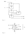
Fig. 1 shows a solar thermochemical system comprising a feeding subsystem (2), a solar thermochemical reactor (1) as defined herein, a quenching subsystem (3), a vacuum generating subsystem (4) a work up subsystem (5). The part of the solar thermochemical system operating under reduced pressure is indicated by the dotted line. The solar concentrating subsystem is not shown, only the incident concentrated solar energy is indicated as "hv". Starting materials are indicated SM; products are indicated as P(s) and P(g); the indices referring to solid or gaseous material. -
Fig. 2 shows an inventive solar thermochemical reactor (1), adapted to operate under reduced pressure. This solar thermochemical reactor comprises reaction tubes (11) equipped with vacuum-proof inlet (12) and a vacuum proof outlet (13); a housing (14) which is equipped with inlet (15) an outlet (16) and with a transparent window (17). The housing (14) may be sealed and filled or purged with a non-oxidizing gas. -
Fig. 3 shows a scheme of the experimental setup including vacuum box (2), tubular section (1) and condenser unit (3). - In the present invention, the following definitions shall apply, unless otherwise specified.
- The terms reactant(s) and starting material(s) are used synonymous and relate to the materials provided to the chemical reaction (such as MexOy, Red, Add) .
- The term product(s) covers the ending materials of the chemical reaction (such as Me).
- The term reactor is known in the field and relates to any device allowing for a chemical reaction. In the context of the present invention, a term preferably refers to a solar thermochemical reactor, as defined herein.
- The term solar thermochemical reactor is known in the field. Particularly, the term relates to a reactor where the energy is supplied, in part or in full, preferably fully, by a source of concentrated solar energy. The energy supplied is predominantly, or solely, in the form of heat.
Such solar thermochemical reactors may operate continuously or discontinuously, preferably continuously. In the context of this invention, a continuous operation refers to an operation mode, were reactants are provided to the reactor and products are removed from the reactor while the reaction is running. Due to the availability of solar energy, the operation of such reactor is intermittent. Accordingly, such reactor is equipped with means for supplying reactants and removing products under reaction conditions, optionally with means for controlling the temperature and with means for receiving concentrated solar energy.
To allow for thermochemical reactions, the reactor material is appropriately chosen, as known to the skilled person. - The term thermochemical reaction is known in the field and includes thermal reduction of metal oxides and carbothermal reduction of metal oxides, both as defined herein.
- The term thermal reduction of metal oxides is known in the field. Particularly, the terms relates to the mere thermal decomposition of a metal oxide (MexOy) to oxygen and a lower valence metal oxide (Mex2Oy2) or to a metal (Me) .
- The term carbothermal reduction of metal oxides is known in the field. Particularly, the term relates to the thermal reduction of a metal oxide (MexOy) in the presence of a carbonaceous reducing agent to carbon monoxide and/or carbon dioxide and a lower valence metal oxide (Mex2Oy2), or to a metal (Me), or to a metal carbide, or mixtures thereof. Carbonaceous reducing agents include solid materials (e.g. coke, charcoal) and gaseous materials (e.g. methane, natural gas, hydrocarbons).
- In more general terms, in a first aspect, the invention relates to methods / processes for reducing metal oxides using solar thermal energy under reduced pressure. As discussed above, reduction of metal oxides using solar thermal energy under ambient pressure is known. It was surprisingly found that these methods may be substantially improved by performing the reaction under reduced pressure. Particularly, it is possible to reduce the reaction temperature, when compared with ambient pressure, while maintaining or even improving conversion rates and product quality. Lowering the reaction temperature is of key importance for industrial applications, as it allows using reactors and systems made of standard materials.
- In an advantageous embodiment, the invention relates to a method for reducing metal oxide particles, said method comprising the steps of: (a) providing metal oxide particles (MexOy), optionally reducing agents (Red) and optionally further components (Add); (b) subjecting the starting materials, or a blend of starting materials, to a reduction reaction; (c) quenching the obtained reaction mixture; (d) optionally further processing the cooled reaction mixture. According to the invention, step (b) is performed by heating the reaction mixture with a source of concentrated sunlight (solar energy). According to the invention, step (b) is performed under a reduced pressure, typically less than 500 mbar.
- This aspect of the invention shall be explained in further detail below:
- [Reduction Reaction, Products of the process] The present invention provides for a method of reducing metal oxide particles MexOy. The inventive method covers thermal reduction (i.e. without reducing agent) and carbothermal reduction (i.e. with a carbonaceous reducing agent) of metal oxides.
The term reduction of metal oxides is used in its broadest sense, i.e. removal of oxygen from a metal oxide. The invention is applicable for obtaining a broad range of desired products, including metals (i.e. metals and alloys of oxidation state 0), and metal containing compounds (oxides, carbides and nitriles of metals are collectively termed: "metal containing compounds").
In a first embodiment metals of oxidation state 0 (pure metals Me, also including alloys) or metal oxides of a reduced oxidation state Mex2Oy2 (y/x > y2/x2) or mixed metal oxides (including perovskites) are the products of the inventive method.
Further, depending on the starting materials and reaction conditions further products are obtainable, including metal carbides and oxy-carbides (if present) as well as metal nitriles.
In case of carbonaceous reducing materials, metal carbides and/or metal oxycarbides may be products of the process. Such metal carbides / oxycarbides may be and undesired side product or the main aim of the process. - In case the chemical reaction is performed in the presence of nitrogen, metal nitrides may be products of the process.
Further, metal alloys may be the products of the process. Such alloys may be obtained by providing two or more metal oxides as the starting materials of the process.
In case of the thermochemical redox cycles, oxygen, hydrogen or carbon monoxide may be the key reaction product, while the reduced oxidation state metal formed is transferred to one or more additional reaction step(s) in order to regenerate the staring material. - [Metal oxides] A wide variety of metal oxides and mixed metal oxides (Me IMeII)xOy are suitable for the method as described herein. The term Metal oxide also includes doped metal oxides and perovskites. Preferred metal oxide particles (MexOy) are selected from the group consisting of the oxides of zinc, aluminum, iron, magnesium, silicon, manganese, titanium, copper, cerium and calcium; preferably selected from the group consisting of the oxides of zinc, and aluminum.
- [Reducing Agents] A wide variety of reducing agents (Red) are suitable for the method as described herein. Preferred are solid reducing agents, typically selected from the group consisting of carbonaceous materials, particularly graphite, carbon black, bio-char, coke, petcoke. Waste carbonaceous materials, such as sludge, tires, fluffcan also be applied as reducing agents. Further, biomass, such as agricultural waste and sewage sludge, can also be applied as reducing agents.
Further preferred as gaseous reducing agents, such as methan, or methan containing mixtures, including natural gas. - [Additives] The inventive method may be facilitated or improved by providing further components, such as natural gas, methane and/or hydrogen.
Further, nitrogen or a nitrogen containing gas, may be added. This allows for the production of metal nitrides.
Further, an inert gas, such as Argon, may be added. Such inert gas may be used as entrainment or sweep gas. The amount of such inert gas may be determined by routine experiments and depends on the reaction conditions and reactor. - [Step a] The starting material is advantageously provided in particulate form, typical particle sizes are in the range of 1-200 microns.
The quality (grade) of the starting material is not crucial and may be chosen according to the desired process by the person skilled in the art. Metal oxides may be purified or may be used as commercially available. Reducing agents, such as graphite or waste biomass, may be used as commercially available or may be pre-treated. For example, non-food grade, waste biomass may be grinded to the specified particle size. Such grinding may be done by using conventional equipment such as hammer-mills.
The starting material is supplied to the reactor (1) by conventional means, such as a conveyer screw.
In case of carbothermal reduction of metal oxides, the ratio of C / MexOy may vary over a broad range and depends on the stochiometry of the reaction. Typically, the ratio C / MexOy is in the range of 1/2 to 3/2, preferably 1/1. - [Step b] Known methods operate at atmospheric pressure; hence reaction temperatures required are much higher. In addition, the recombination of the gaseous products (if occurring) is very fast decreasing the yield of the desired product. By lowering reaction pressure, both reaction temperature and concentrations of the gaseous products are lower which decreases the rates of recombination reactions and makes quenching more effective. Typical reaction pressures are below 500 mbar, preferably below 200 mbar. Suitable ranges are, for example 1-500 mbar, preferably 10-250 mbar, particularly 25 - 200 mbar.
The reduction reaction of step (b) is performed by providing the required heat at high temperatures for the endothermic transformation with a source of concentrated solar energy. It is believed that heat needs to be provided not only for heating, but more importantly for the enthalpy change of the reaction.
Typical reaction times τ are within the range of 0.1 - 10 sec, such as 1 sec. - [Step c] It was found that a fast quench from the reaction temperature to the condensation temperature of the desired product is beneficial for the inventive method.
Accordingly, the quench temperature depends on the aimed product and is typically below 1000°C, preferably below 500°C.
Further, quenching is "fast" meaning the time for quenching reduces, or inhibits, recombination reactions. Suitable times depend on the specific reaction, but are typically within less than 10 seconds, preferably below 1 second. Suitable quench rates are faster than 600°C/s, preferably faster than 1000°C/s.
A fast quench is particularly beneficial for the carbothermal reduction of alumina (section Al production, eq. 1.1). In this embodiment, quenching to a temperature below 1000°C within 5s, preferably below 900°C within 3s was found beneficial.
Further, a fast quench is particularly beneficial for thermal reduction of metal oxides; i.e. for methods where no Reducing agent is present (e.g. section ZnO/Zn+O2 cycle, eq. 3.1). In this embodiment, quenching to a temperature below 1000°C within 5s was found beneficial. Known methods use an inert gas to quench the product mixture. There are two problems associated with this approach: (1) the substantial amount of inert gas is needed which increases required pumping power for achieving preferred vacuum levels in the reactor and the energy required to recycle the inert gas, and (2) the gas quench is not as efficient hence the product vapors deposit on any cold surfaces within the system, thereby making product recovery tedious and impractical. Accordingly, in one preferred embodiment, the product is quenched by contacting a cold solid surface, preferably a cold solid moving surface. This may be accomplished by using standard equipment, such as ash coolers.
Other quenching methods may be suitable in addition to the above, or as an alternative. In a further embodiment, quenching may be achieved by diluting with inert gas. In a further embodiment, quenching may achieved by expanding through a de Laval nozzle. - [Step d] The further processing of the products obtained follows known routes and depends on the overall process. Generally speaking, the solid products obtained are either purified and/or further processed (in case of the production of metals); or recycled (in case of the production of fuels).
- In an advantageous embodiment, the invention provides for a method as described herein, wherein steps a), b) and c) are performed continuously.
- Further, the invention provides for the use of methods, reactors and systems as described herein (i) in the production of metals and metal containing compounds (such as aluminum and/or aluminum carbide), (ii) in the production of fuels (such as hydrogen and/or carbon monoxide and/or hydrocarbons), from water and/or carbon dioxide via thermochemical redox cycles, and (iii) in performing thermochemical redox cycles for separating oxygen from gases (iv) in the production of ammonia from water and nitrogen via terhmochemical redox cycles. These uses shall be explained in further detail below.
- [Al production] In an advantageous embodiment, the invention provides for a method as described herein, wherein the metal oxide particles are aluminum oxide particles, the reducing agent is a carbon source (C), such as graphite or methane, and the reaction product is aluminum or an aluminum containing compound.
Al2O3 + 3C -> 2Al + 3CO (1.1)
Consequently, the invention also provides for the use of a method as described herein for manufacturing aluminum or aluminum alloys, or aluminum carbides. The idealized equation (1.1) only provides for the overall reaction, summarizing a myriad of reaction steps. - [ZnO+C/Zn+CO cycle] In a further advantageous embodiment, the invention provides for a method as described herein, wherein the metal oxide particles are Zinc oxide particles, the reducing agent is graphite and the reaction product is zinc. Consequently, the invention also provides for the use of a method as described herein for manufacturing zinc. This reaction may be part of a catalytic cycle where in a first step zinc and water are reacted to give zinc oxide and hydrogen and in a second step zinc oxide and carbon is reduced (as described herein) to give zinc and carbon monoxide.
ZnO + C -> Zn + CO (2.1) reduction according to this invention
Zn + H2O -> ZnO + H2 ( 2 . 2 ) formation of hydrogen, regeneration of metal
Zn + CO2 -> ZnO + CO (2.3) formation of carbon monoxide, regen.of metal
Zn + zCO2+ (1-z)H2O -> ZnO + ZCO + ( 1-z ) H2, z<1 ( 2.4) formation of syngas, regen.of metal
H2O + C -> H2 + CO (2.5) syngas, reaction of residual carbon, if present. - Consequently, the invention also provides for the use of a method as described herein for manufacturing syngas from water and carbon dioxide (equation 2.4).
- [ZnO/Zn+O2 cycle] In a further advantageous embodiment, the invention provides for a method as described herein, wherein the metal oxide particles are Zinc oxide particles, no reducing agent is provided and the reaction product is zinc. Consequently, the invention also provides for the use of a method as described herein for manufacturing zinc. This reaction may be part of a catalytic cycle where in a first step zinc and water are reacted to give zinc oxide and hydrogen and in a second step zinc oxide is reduced (as described herein) to give zinc and oxygen.
ZnO -> Zn + 1/202 (3.1) reduction according to this invention
Zn + H2O -> ZnO + H2 (3.2) formation of hydrogen, regeneration of metal
Zn + CO2 -> ZnO + CO (3.3) formation of carbon monoxide, regen. of metal
Consequently, the invention also provides for the use of a method as described herein for thermal splitting of water to hydrogen and oxygen (equations 3.1. and 3.3) and/or or carbon dioxide to carbon monoxide and oxygen (equations 3.1. and 3.2.).
Alternatively, reaction 3.1 in combination with 2.4 provide for the use of a method described herein for producing in separate steps oxygen and syngas from water and carbon dioxide according to equation 3.4.
zCO2+ (1-z) H2O -> zCO + ( 1-z ) H2 + 1/202, z<1 (3.4) formation of syngas, simultaneous water and carbon dioxide splitting. - [Al2O3 / A1N thermochemical cycle] In a further advantageous embodiment, the invention provides for a method as described herein, wherein in a thermochemical cycle ammonia is produced in a two step process from nitrogen and water. Details of such method are provided in Galvez et al (cited above, incorporated by reference in its entirety), disclosing ammonia production via two step A1203 / A1N thermochemical cycle.
Al2O3 + C + N2 -> 2AlN + 3CO (4.1) reduction according to this invention
Al2O3 + 3CH4 + N2 -> 2AlN + 6H2 + 3CO (4.2) reduction according to this invention
2AlN + 3H2O -> Al2O3 + 2NH3 (4.3) formation of ammonia, regeneration of metal oxide
The first endothermic step is the production of ALN by carbothermal reduction of Al203 in a N2 atmosphere at above 1500°C / without the need of adding a catalyst. This step is performed according to the method as described herein and schematically outlined in eq. 4.1 or 4.2. The second exothermic step is the steam hydrolysis of A1N to produce NH3 and reform Al2O3; the latter is recycled to the first step (e.q. 4.3). In this embodiment, it may be beneficial to perform quenching step (c) by diluting with nitrogen. - [Cu2O / CuO + 02 cycle] In a further advantageous embodiment, the invention provides for a method as described herein, wherein in a thermochemical redox cycle oxygen is separated from a gas mixture containing oxygen. Details of such method are provided in Haenchen et al (cited above, incorporated by reference in its entirety) disclosing a two step thermally-Driven Copper Oxide Redox Cycle for the Separation of Oxygen from Gases.
2CuO -> Cu2O + 1/2O2 (5.1) reduction according to this invention
Cu2O + 1/2O2 -> 2CuO (5.2) removal of oxygen; regeneration of metal oxide This process is particularly useful for removal of oxygen from diute gas streams.
The first endothermic step is the reduction of CuO in air at above 1300°C / without the need of adding a reducing agent. This step is performed according to the method as described herein and schematically outlined in eq. 5.1. - In a second aspect, the invention relates to new solar thermochemical reactors and systems. These solar thermochemical reactors and systems are suitable for performing the processes as described herein. This aspect of the invention shall be explained in further detail below, whereby reference is made to
fig. 1 regarding the solar thermochemical reactor system andfig. 2 regarding the solar thermochemical reactor. - [Reactor (1)] The solar thermochemical reactor (1) is an improved and novel alternative to known solar thermochemical reactors. It distinguishes from previously described solar thermochemical reactors at least in means for operating continuously under reduced pressure. Advantageously, the solar thermochemical reactor is a high temperature, low pressure, aerosol flow, solar thermochemical reactor.
- Accordingly, the invention provides for a solar thermochemical reactor (1) comprising one or more reaction tubes (11) equipped with vacuum-proof inlet (12) (for receiving starting materials) and an outlet (13) (for releasing the products) and optionally a housing (14). Such housing may be equipped with inlet (15) and outlet (16) for purge gas and/or with a transparent window (17). Such reactor is adapted to operate under reduced pressure. Typically, the outlet (13) is in communication with a quenching system (3) which operates under vacuum as well. Consequently, the outlet (13) needs not to be vacuum proof.
- In a further embodiment (
fig. 2 ), the invention provides a solar thermochemical reactor as described herein comprising (i) one or more reaction tubes (11) equipped with vacuum-proof inlet (12) and outlet (13) and (ii) a housing (14) which is equipped with inlet (15) and outlet (16) for purge gas and a quartz window (17) and whereby the quartz window (17) is not in direct contact with the reactants / products of the reaction tubes (11). Such reactor is adapted to operate under reduced pressure and avoids a contact of the quartz window with the reactants and with the products. - In a further embodiment, the invention provides for a solar thermochemical reactor as described herein, comprising a tube or a multitude of tubes (11) and a cylindrical envelope (14), with vacuum or inert gas in the space between the tubes (11) and the cylinder (14). In this embodiment, the cylinder is preferably made of quartz.
- In a further embodiment, such reactor comprises a solar cavity receiver (i.e. means for receiving solare energy). The solar cavity-receiver is designed to efficiently capture concentrated solar radiation entering through an aperture and transfer the resulting high-temperature heat to a solar thermochemical reactor situated within. The aperture may be open to the atmosphere, thereby exposing the interior of the cavity to ambient air. Alternatively, a transparent window (17), made for example of quartz, may be positioned in front of the aperture, thereby isolating the interior of the cavity from the ambient air. The latter allows for an oxygen-free atmosphere within the cavity when it is purged by an inert gas at ambient pressure ensuring no pressure difference across the window.
Tubular solar thermochemical reactors are particularly suitable for the processes described herein. Accordingly, the solar thermochemical reactor is represented by either a single tube or a multitude of tubes (11). These tubes are made of a material having appropriate thermo-mechanical properties, such as graphite. The exterior and/or interior of the tube(s) may be coated by a suitable material which chemically protects it from the reactants, products and / or the surrounding atmosphere. Known approaches for performing solar-thermal reactions under vacuum teach implementing direct irradiation of the material reacting under vacuum (Kruesi et al, as incorporated by reference). This was accomplished by passing the radiation through a quartz window which isolates the reaction zone from the surroundings. There are two problems associated with this approach: (1) the quartz window is subjected to a substantial pressure difference jeopardizing its mechanical integrity and limiting its size, and (2) the quartz window is directly exposed to the reaction environment. The latter could easily cause clouding of the window by the dust carried by the gas evolving from the reaction. All of this has adverse effect on the operability of said concepts. Accordingly, the invention provides a solar thermochemical reactor for solar-thermal reaction where a quartz window (17) is decoupled from the reaction environment and exposed to the same pressure from both sides. This may be accomplished by providing reaction tubes (11) within a housing (14), where the quartz window (17) is located in the housing and the cavity between housing and reaction tubes is purged with an inert gas under ambient pressure. The provision to purge the cavity by an inert gas enables graphite as the material of construction for the tubes. This is a low-cost, machinable material with outstanding thermo-mechanical properties.
Further, maintaining low partial pressures of oxygen (released by the thermal reduction under vacuum) may extend the oxidation of the tubes (11) over a period of time that is long enough to be commercially acceptable. Alternatively, the graphite of the reaction tubes may be protected by a suitable oxidation-resistant coating. According to a further embodiment, oxidation resistant materials - other than graphite - may be used for the reaction tubes (11). Such materials include alumina, zirconia, silicon carbide and sapphire. Allthough these materials generally have inferior thermochemical properties; they may be beneficial in view of oxoidation resistance and/or manufacturing.
According to a further embodiment, conventional materials of construction and standard equipment are used for the solar thermochemical reactor (1).
The tubes (11) are sealed and incorporated into a vacuum system as outlined below. Sealing may be achieved by selecting appropriate feeder (2) and quencher (3) and by selecting appropriate valves installed into a standard lock-hopper system (for disengaging and storing product). - [Reactor System] The invention further provides for a solar thermochemical system comprising a feeding system (2); a solar thermochemical rector (1) (particularly as defined herein); a quenching system (3); a vacuum generating system (4); optionally a work-up system (5); and optionally a sunlight collecting system (c.f.
fig. 1 ) . - In a further embodiment, the invention provides for a solar thermochemical system comprising a cavity-receiver for capturing and distributing concentrated solar energy to a solar thermochemical reactor (1), a feeder (2) (to continuously supply starting materials), a quencher (3) (for cooling of the reaction products), and a vacuum generating system (4) (for generating an environment of reduced pressure in the feeder, solar thermochemical reactor and quencher). This system is adapted and suited for carrying out the thermal reduction of metal oxides with or without reducing agents.
- [Feeding system (2)] Feeding systems are commercially available items and may be adapted to the specific requirements by the skilled person. Suitable are, for example, feed hoppers equipped with conveying screws.
- [Quenching system (3)] Cooling devices are commercially available items and may be adapted to the specific requirements by the skilled person. Suitable quenchers are adapted to operate under reduced pressure and at temperatures adapted to the reaction conditions.
In one embodiment, the cooling device ensures rapid cooling of the products to avoid further side reactions.
In one further embodiment, the quencher design may be optimized to partially allow recombination reactions. For example, by recombining apart of the Zn and 02 produced by the thermal reduction of ZnO, a mixture of Zn and ZnO is produced that allows for the conversion of Zn in the oxidation step of the C02 and/or H20 splitting cycle that is substantially higher than the one achieved when using the pure Zn.
In one further embodiment, product quenching is accomplished by contacting a cold solid surface using a commercial ash cooler, such as Holo Scru ®. The vapors are forced to condense and solidify on a moving surface provided by the equipment itself and/or by moving cold condensed product. Advantageously, this solid surface is designed to transfer the resulting solids into a storage bin via disengaging lock-hoppers. - [Vacuum generating system (4)] Vacuum generating systems are commercially available items and may be adapted to the specific requirements by the skilled person.
- [Work-up system (5)] The work-up system is adapted to the aimed overall-process. In case of thermal or carbothermal reduction of metal oxides, it is designed to purify or further process products obtained. In case of thermo-chemical redox cycle, it is designed to recycle and optionally purify products to complete the catalytic cycle. Such work-up systems are commercially available items and may be adapted to the specific requirements by the skilled person.
- In one embodiment, the product may be further refined in a subsequent process step to recover desired material. For example, an Al4C3/ Al2O3 mixture, resulting from the carbothermal reduction of alumina, may be slagged in a separate step to recover the aluminum metal (e.g. as disclosed in
US 6440193 , incorporated by reference).
In one further embodiment, the product may be oxidized to produce a fuel. For example, (a) Zn as a product of the thermal reduction of ZnO or (b) a Zn/C containing mixture as a product of the carbothermal reduction of ZnO may be oxidized by a H20/C02 mixture to produce clean syngas (a H2/CO mixture). - [Sunlight collecting system (6)] Solar collectors are known in the field and may be adapted to the specific reaction by the skilled person.
- [Operating the system] The reactor is fed by solid starting materials comprising metal oxides as defined herein optionally combined with reducing agents (Red) and further components (Add) as defined herein. The reducing agent may be in the solid, liquid, or gas phase. The feed is entrained into the hot reactor zone under vacuum and reacted in either entrained-flow or moving-bed mode, depending on a residence time required for the reaction. The vacuum conditions allow for the occurrence of the desired forward reaction at temperatures lower than those needed if the reaction is to be carried out at ambient pressure (Le Chatelier's principle). The product mixture may contain the metal in liquid and gas phases, oxygen containing gaseous products (02, C02, CO, etc.), solid side-products (Mex2Oy2, metal carbides, etc.) and starting materials. In order to precipitate the metal before it recombines into the oxide or other undesired products, the product mixture is rapidly quenched, e.g. by intimate contact with a cold inert gas and/or solid surface, and/or by expansion through a de Laval nozzle. The cold solid product is purged with an inert gas (e.g. by using a disengaging lock-hopper), pressurized to the ambient pressure, and discharged (e.g. to a product storage bin).
- To further illustrate the invention, the following examples are provided. These examples are provided with no intend to limit the scope of the invention.
- The performance of carbothermal reductions of A1203 and ZnO under reduced pressure according to the proposed invention was evaluated against their counterparts at standard pressure through four examples summarized in Table 1 using the experimental setup shown in
Figure 3 . - The setup comprises three major parts: a powder feeder within a vacuum-tight steel box (2), a graphite reactor tube within a quartz tube enclosure sealed to the vacuum box (1), and a cooler/condenser unit sealed to the quartz tube ( 3 ) .
- The custom made cylindrical vacuum box (1) was fabricated out of a 550 mm long and 250 mm ID steel tube having a wall thickness of 2 mm. A powder feeder (Lambda Doser, Lambda Laboratory Instruments, Brno, Czech Republic) is placed inside the vacuum box and positioned to discharge particles directly into a graphite tube having 26.3 mm OD and wall thickness of 1.6 mm. The graphite tube was placed inside a transparent quartz glass tube that was connected to the condenser/quencher unit. This assembly was connected to a vacuum pump (
Adixen ACP 15, Pfeiffer Vacuum GmbH, Asslar, Germany) which was used to pull vacuum and to pump the product gases out of the reactor. The system pressure was measured in the vacuum box by a piezoresistive absolute pressure sensor (Type 4045A2, Kistler Group, Winterthur, Switzerland). In the experiments performed at atmospheric pressure, the entire system was first evacuated and then filled and purged with argon. - The graphite tube was heated by concentrated radiation generated via the high flux solar simulator described in the by Furler et al which is cited above and incorporated by reference (particularly
section 2, andfig. 1 ). The concentrated radiation was capable of creating a ~25 mm long hot zone located 3-4 cm above the top end of the condenser. The temperature of the inside reactor wall in the middle of the hot zone was measured by a type C thermocouple in the absence of a reaction in order to eliminate effects of fouling by the falling particles. This temperature was correlated to the outside graphite tube temperature T3 measured 165 mm from its top end. It has been found that T3 temperature of 480°C corresponded to the hot zone temperatures of 1750°C. - The particle size distributions of the reactants used in the Examples were measured by Horiba LA-950 as follows:
- C: Carbon Black (Black Pearls 2000, CABOT Corporation, Billerica, US; particle size: D10=4.9 µm, D50= 15.9 µm, D90=124.3µm, feedstock: gas or liquid hydrocarbons)
- A1203: (particle size: D10=48 µm, D50= 79 µm, D90=113µm)
- ZnO: (Sigma Aldrich Inc., St. Louis, US; D10=0.73 µm, D50= 1.05 µm, D90=2.70 µm)
- The reactants were mechanically blended in stoichiometric ratios (see Table 1) and loaded into the powder feeder inside the vacuum box. After sealing and evacuating the system to a desired pressure, the reactor was heated to a setpoint temperature T3 via a high-flux solar simulator. The reactants were then commenced from the feeder and entrained into the graphite tube using a small amount of argon. During reaction, argon was also flown through the quartz enclosure. Due to both product condensation on the filter before the vacuum pump and increase in the system temperature, the pressure was increasing during the reaction; therefore, Table 1 reports both the initial and final pressures of the experiments.
- The feeding rate of the powder feeder was set equal for each Example. However, the resulting powder feeding rate was not accurately reproducible and therefore the feeding time and the total mass fed are shown in table 1. The amount of reactants fed was determined by weighing the retainer in the feeder after the reaction.
- The products of the reaction are quenched rapidly in the condenser unit with intention to minimize backward and side reactions. It should be mentioned that no special attention has been made to optimize the performance of the quencher thus the intention of the examples summarized in Table 1 was only to compare relative performance of the system under different conditions.
- The reaction product gases were analyzed by using a gas-phase chromatograph (GC) (Varian 490 Micro GC, Varian, Middleburg, The Netherlands), an IR gas analyzer (Ultramat 23, Siemens, Munich, Germany) and a thermal conductivity gas analyzer (Calomat 6, Siemens, Munich, Germany). H2 was detected because of moisture content in the graphite tube and in the reactants. In the hot zone of the reactor the moisture reacts with carbon and forms an equimolar mixture of H2 and CO according to the reaction:
H2O+C→H2 +CO (0.1)
- Therefore, the amount of CO produced from a reaction of metal oxide and carbon was estimated as the difference between the total amounts of CO and H2 produced during the experiment. This value is in Table 1 designated H2 corrected CO.
- The oxygen conversion is a measure of the reaction efficiency based on the CO production. It is defined as the ratio of the molar amount of oxygen contained in the produced CO (H2 corrected CO) and the molar amount of oxygen contained in the amount of metal oxide fed. If MA1203=101.96 g mol-1, MC=12.01 g mol-1, and MZnO=81.41 g mol-1 are the molar masses of A1203, C, and ZnO respectively, the Oxygen conversion is calculated as follows:
- (a) for the system A1203+3C,

- (b) for the system ZnO+C,

- The results shown in Table 1 indicate higher Oxygen conversions achieved under reduced pressure in Examples 1 and 3 compared to Examples 2 and 4 completed at atmospheric pressure.
| Example 1 (inventive) | Example 2 (comparative) | Example 3 (inventive) | Example 4 (comparative) | |
| chemistry / stoichiometry | Al2O3+3C | Al2O3+3C | ZnO+C | ZnO+C |
| graphite tube length [mm] | 430 | 430 | 450 | 450 |
| hot zone length [mm] | 25 | 25 | 25 | 25 |
| initial pressure [mbar] | 18 | ~1000 | 20 | ~1000 |
| final pressure [mbar] | 238 | ~1000 | 400 | ~1000 |
| ref. temp. T3 [°C] | 481 | 524 | 528 | 527 |
| feeding time [min] | 9.3 | 15 | 20.1 | 12.4 |
| total mass fed [g] | 1.80 | 2.77 | 4.93 | 3.30 |
| Ar carrier gas flow rate [1n/min] | 1.00 | 1.00 | 1.00 | 1.00 |
| CO gas produced [mmol] | 11.40 | 9.77 | 31.80 | 15.30 |
| H2 gas produced [mmol] | 4.50 | 4.66 | 4.45 | 2.14 |
| H2 corrected CO [mmol] | 6.90 | 5.11 | 27.36 | 13.16 |
| Oxygen conversion [%] | 17.6 | 8.5 | 51.9 | 37.3 |
Claims (17)
- A method for reducing metal oxide particles, comprising the steps of:a) providing (i) metal oxide particles (MexOy) (ii) optionally reducing agents (Red) and optionally further components (Add);b) subjecting the starting materials to a reduction reaction;c) quenching the obtained reaction mixture;d) optionally further processing the cooled reaction mixture;
whereby step (b) is performed by providing the required heat at high temperatures for the endothermic transformation with a source of concentrated solar energy; and
whereby step (b) is performed under a reduced pressure between 1 - 500 mbar. - The method of claim 1, wherein in step a)• said metal oxide particles (MexOy) are selected from the group consisting of the oxides of zinc, aluminum, iron, magnesium, silicon, manganese, titanium, copper, and calcium; and / or• said metal oxide particles are mixed oxides (MeIMeII)xOy, particularly perovskites.• said reducing agents (Red) are selected from the group consisting of carbonaceous materials; and /or• said further components (Add) are selected from the group consisting of natural gas, methane, and hydrogen; and / or• said further components (Add) are selected from the group consisting of nitrogen and nitrogen containing gases.
- The method of claim 1, wherein in step c) quenching from the reaction temperature to the condensation temperature of the desired product is effected within a time period of 5 sec or less.
- The method according to any of the preceding claims, wherein the method provides• pure metals (Me); and / or• metal alloys; and /or• mixed metal oxides (MeIMeii)xDy, particularly perovskites.• metal oxides (Mex2Oy2) with a reduced oxidation state of the metal (y/x > y2/x2); and / or• metal carbides; and /or• metal nitrides.
- The method according to any of the preceding claims, wherein steps a), b) and c) are performed continuously.
- The method according to any of the preceding claims, wherein in step a) the starting materials are supplied by conveyer screw.
- The method according to any of the preceding claims, wherein in step b) reaction times τ are within the range of 0.1 - 10 sec and reaction pressure is in the range of 10 - 250 mbar.
- The method according to any of the preceding claims, wherein in step c) the product is quenched by• contacting a cold solid surface, preferably a cold solid moving surface, and/or• by diluting with nitrogen, and/or• by diluting with inert gas, and/or• by expanding through a de Laval nozzle.
- The method according to any of the preceding claims, wherein in step d) the solid products obtained are• further purified and/or further processed (in case of the production of metals), or• recycled (in case of the production of fuels).
- The method according to any of the preceding claims, wherein no reducing agent (Red) is provided.
- The method according to any of the preceding claims, whereina) the metal oxide particles are Zinc oxide particles, no reducing agent is provided and the solid reaction product is Zinc; orb) the metal oxide particles are aluminum oxide particles, the reducing agent is graphite and the solid reaction product is aluminum; orc) the metal oxide particles are aluminum oxide particles, the reducing agent is methane and the solid reaction product is aluminum; ord) the metal oxide particles are copper oxide particles, and the solid reaction product is copper or a reduced copper oxide for use in a thermochemical redox cycle to separate oxygen from a gas mixture containing oxygen; ore) the metal oxide particles are aluminum oxide particles, the reducing agent is a carbonaceous source, the Additive is nitrogen and the solid reaction product is aluminum nitride.
- Use of a method according to any of the preceding claimsa) for manufacturing aluminum or aluminum alloys or aluminum carbides, preferably aluminum or aluminum carbides ; orb) in a redox cycle for transferring oxygen, particularly for manufacturing carbon monoxide and / or hydrogen and/or hydrocarbons, and or ammonia; orc) in a redox cycle for separating oxygen from a gas mixture containing oxygen.
- A solar thermochemical reactor (1) which is adapted to operate under reduced pressure comprising:• one or more reaction tubes (11) equipped with vacuum-proof inlet (12) for receiving starting materials and a vacuum proof outlet (13) for releasing products and• a housing (14) which is optionally equipped with inlet (15) and outlet (16) for purge gas and a transparent window (17).
- The reactor of claim 12 comprising• one or more reaction tubes (11) equipped with vacuum-proof inlet (12) and outlet (13) and• a housing (14) which is equipped with inlet (15) and outlet (16) for purge gas and with a transparent window (17) and• whereby the transparent window is not in direct contact with the reactants.
- The reactor of claim 13 or 14, wherein said tubes (11) are made ofa) graphite, which is optionally coated; orb) a material selected from the group consisting of alumina, zirconia, silicon carbide and sapphire.
- The reactor according to any of claims 13 - 15 comprising• one or more reaction tubes (11) and• a housing (14) in the form of a cylindrical quartz envelope• whereby the space between the tubes (11) and the quartz cylinder (14) is either under vacuum or filled with an inert gas or purged with an inert gas.
- A reactor system comprising• a feeding system (2);• a rector (1) as defined in any of claims 12 to 16;• a quenching system (3);• a vacuum generating system (4)• optionally a work-up system (5);• optionally a solar concentrating system.
Priority Applications (2)
| Application Number | Priority Date | Filing Date | Title |
|---|---|---|---|
| EP12007520.5A EP2728022A1 (en) | 2012-11-05 | 2012-11-05 | Methods and systems for reducing metal oxides |
| PCT/EP2013/003291 WO2014067664A2 (en) | 2012-11-05 | 2013-11-01 | Methods and systems for reducing metal oxides |
Applications Claiming Priority (1)
| Application Number | Priority Date | Filing Date | Title |
|---|---|---|---|
| EP12007520.5A EP2728022A1 (en) | 2012-11-05 | 2012-11-05 | Methods and systems for reducing metal oxides |
Publications (1)
| Publication Number | Publication Date |
|---|---|
| EP2728022A1 true EP2728022A1 (en) | 2014-05-07 |
Family
ID=47143497
Family Applications (1)
| Application Number | Title | Priority Date | Filing Date |
|---|---|---|---|
| EP12007520.5A Withdrawn EP2728022A1 (en) | 2012-11-05 | 2012-11-05 | Methods and systems for reducing metal oxides |
Country Status (2)
| Country | Link |
|---|---|
| EP (1) | EP2728022A1 (en) |
| WO (1) | WO2014067664A2 (en) |
Cited By (2)
| Publication number | Priority date | Publication date | Assignee | Title |
|---|---|---|---|---|
| EP3470551A4 (en) * | 2016-06-06 | 2019-08-21 | Lanzhou Jinfule Biotechnology Co., Ltd. | SOLAR THERMAL REDUCTION DEVICE BASED ON ALUMINUM HYDROXIDE FOR ALUMINUM-AIR FUEL CELL |
| WO2019213787A1 (en) * | 2018-05-07 | 2019-11-14 | Synhelion Sa | Solar receiver-reactor |
Families Citing this family (3)
| Publication number | Priority date | Publication date | Assignee | Title |
|---|---|---|---|---|
| US10400309B2 (en) | 2013-08-29 | 2019-09-03 | The Regents Of The University Of Colorado, A Body Corporate | Carbothermal reduction reactor system, components thereof, and methods of using same |
| JP7553235B2 (en) | 2019-10-31 | 2024-09-18 | 株式会社きもと | Light Diffusion Film |
| CN113200517B (en) * | 2021-04-30 | 2023-10-10 | 华南理工大学 | A solar thermochemical energy conversion system using electric furnace dust as circulating medium |
Citations (3)
| Publication number | Priority date | Publication date | Assignee | Title |
|---|---|---|---|---|
| US6440193B1 (en) | 2001-05-21 | 2002-08-27 | Alcoa Inc. | Method and reactor for production of aluminum by carbothermic reduction of alumina |
| US20060188433A1 (en) | 2000-05-08 | 2006-08-24 | Weimer Alan W | Metal-oxide based process for the generation of hydrogen from water splitting utilizing a high temperature solar aerosol flow reactor |
| US20100237291A1 (en) * | 2009-06-09 | 2010-09-23 | Sundrop Fuels, Inc. | Systems and methods for solar-thermal gasification of biomass |
-
2012
- 2012-11-05 EP EP12007520.5A patent/EP2728022A1/en not_active Withdrawn
-
2013
- 2013-11-01 WO PCT/EP2013/003291 patent/WO2014067664A2/en not_active Ceased
Patent Citations (3)
| Publication number | Priority date | Publication date | Assignee | Title |
|---|---|---|---|---|
| US20060188433A1 (en) | 2000-05-08 | 2006-08-24 | Weimer Alan W | Metal-oxide based process for the generation of hydrogen from water splitting utilizing a high temperature solar aerosol flow reactor |
| US6440193B1 (en) | 2001-05-21 | 2002-08-27 | Alcoa Inc. | Method and reactor for production of aluminum by carbothermic reduction of alumina |
| US20100237291A1 (en) * | 2009-06-09 | 2010-09-23 | Sundrop Fuels, Inc. | Systems and methods for solar-thermal gasification of biomass |
Non-Patent Citations (8)
| Title |
|---|
| FURLER ET AL., ENERGY ENVIRON SCI, vol. 5, 2012, pages 6098 |
| GALVEZ ET AL., INDUSTRIAL & ENGINEERING CHEMISTRY RESEARCH, vol. 46, 2007, pages 2042 - 2046 |
| GALVEZ M E; HALMANN M; STEINFELD A: "Ammonia production via a two-step Al2O3/AlN thermochemical cycle. 1. Thermodynamic, environmental, and economic analyses", INDUSTRIAL AND ENGINEERING CHEMISTRY RESEARCH, vol. 46, 2007, pages 2042 - 2046, XP002694927 * |
| HAENCHEN ET AL., INDUSTRIAL & ENGINEERING CHEMISTRY RESEARCH, vol. 51, 2012, pages 7013 FF |
| KODAMA T: "High-temperature solar chemistry for converting solar heat to chemical fuels", PROGRESS IN ENERGY AND COMBUSTION SCIENCE, ELSEVIER SCIENCE PUBLISHERS, AMSTERDAM, NL, vol. 29, no. 6, 1 January 2003 (2003-01-01), pages 567 - 597, XP004470708, ISSN: 0360-1285, DOI: 10.1016/S0360-1285(03)00059-5 * |
| KRUESI ET AL., METALLURGICAL AND MATERIALS TRANSACTIONS B, vol. 42B, February 2011 (2011-02-01), pages 254 |
| KRUESI M ET AL: "Solar Aluminum Production by Vacuum Carbothermal Reduction of Aluminaâ Thermodynamic and Experimental Analyses", METALLURGICAL AND MATERIALS TRANSACTIONS B, SPRINGER-VERLAG, NEW YORK, vol. 42, no. 1, 14 December 2010 (2010-12-14), pages 254 - 260, XP019879299, ISSN: 1543-1916, DOI: 10.1007/S11663-010-9461-6 * |
| MULLER ET AL: "Transient heat transfer in a directly-irradiated solar chemical reactor for the thermal dissociation of ZnO", APPLIED THERMAL ENGINEERING, PERGAMON, OXFORD, GB, vol. 28, no. 5-6, 24 January 2008 (2008-01-24), pages 524 - 531, XP022433010, ISSN: 1359-4311, DOI: 10.1016/J.APPLTHERMALENG.2007.05.002 * |
Cited By (4)
| Publication number | Priority date | Publication date | Assignee | Title |
|---|---|---|---|---|
| EP3470551A4 (en) * | 2016-06-06 | 2019-08-21 | Lanzhou Jinfule Biotechnology Co., Ltd. | SOLAR THERMAL REDUCTION DEVICE BASED ON ALUMINUM HYDROXIDE FOR ALUMINUM-AIR FUEL CELL |
| US11098388B2 (en) * | 2016-06-06 | 2021-08-24 | Lanzhou Jinfule Biotechnology Co. Ltd. | Aluminum hydroxide solar powered thermal reduction device for aluminum-air fuel cell |
| WO2019213787A1 (en) * | 2018-05-07 | 2019-11-14 | Synhelion Sa | Solar receiver-reactor |
| US12240756B2 (en) | 2018-05-07 | 2025-03-04 | Synhelion Sa | Solar receiver-reactor |
Also Published As
| Publication number | Publication date |
|---|---|
| WO2014067664A2 (en) | 2014-05-08 |
| WO2014067664A3 (en) | 2016-04-28 |
Similar Documents
| Publication | Publication Date | Title |
|---|---|---|
| CN1052759C (en) | Fast quench reactor and method | |
| US4128624A (en) | Method for introducing carbon into evacuated or pressurized reaction vessels and reaction products therefrom | |
| US20180178292A1 (en) | Novel Methods of Metals Processing | |
| Voitic et al. | High purity pressurised hydrogen production from syngas by the steam-iron process | |
| WO2014067664A2 (en) | Methods and systems for reducing metal oxides | |
| US10400309B2 (en) | Carbothermal reduction reactor system, components thereof, and methods of using same | |
| EP2641889B1 (en) | Methanol production process | |
| FR2526048A1 (en) | PROCESS FOR RECOVERING OXYGEN FROM CARBON DIOXIDE CLEARANCE | |
| JP5549732B2 (en) | Hydrogen production method and apparatus | |
| US20130195746A1 (en) | Method and system for production of silicon and devicies | |
| EP2610214B1 (en) | Method for converting nitrogen (N2) into ammonia and/or nitric acid | |
| Francis et al. | Manganese oxide dissociation kinetics for the Mn2O3 thermochemical water-splitting cycle. Part 1: Experimental | |
| Chuayboon et al. | Solar metallurgical process for high-purity Zn and syngas production using carbon or biomass feedstock in a flexible thermochemical reactor | |
| US4184852A (en) | Method for making methane from metal carbides | |
| SU691071A3 (en) | Phosgene producing method | |
| Rayne | Thermal carbon dioxide splitting: A summary of the peer-reviewed scientific literature | |
| EP0004456B1 (en) | Methanation of carbon monoxide without prior separation of inert gases | |
| EP3472123A1 (en) | A method and system for carbon capture and recycling | |
| Vishnevetsky et al. | Features of solar thermochemical redox cycles for hydrogen production from water as a function of reactants’ main characteristics | |
| WO2024059929A1 (en) | Low carbon emission process for the production of silicon | |
| US3970745A (en) | Method for producing hydrogen from water | |
| JP4120717B2 (en) | Method for producing a mixed gas of carbon monoxide and hydrogen | |
| CN115066480B (en) | Method for preparing acetylene (C2H2) | |
| Zhang et al. | Performance of a tubular oxygen-permeable membrane reactor for partial oxidation of CH4 in coke oven gas to syngas | |
| KR101231604B1 (en) | Decomposition Method of Carbon Dioxide by Thermochemical Cycle Using Germanium Oxide |
Legal Events
| Date | Code | Title | Description |
|---|---|---|---|
| PUAI | Public reference made under article 153(3) epc to a published international application that has entered the european phase |
Free format text: ORIGINAL CODE: 0009012 |
|
| 17P | Request for examination filed |
Effective date: 20121105 |
|
| AK | Designated contracting states |
Kind code of ref document: A1 Designated state(s): AL AT BE BG CH CY CZ DE DK EE ES FI FR GB GR HR HU IE IS IT LI LT LU LV MC MK MT NL NO PL PT RO RS SE SI SK SM TR |
|
| AX | Request for extension of the european patent |
Extension state: BA ME |
|
| STAA | Information on the status of an ep patent application or granted ep patent |
Free format text: STATUS: THE APPLICATION IS DEEMED TO BE WITHDRAWN |
|
| 18D | Application deemed to be withdrawn |
Effective date: 20141108 |