EP2727823A2 - Security door and security area - Google Patents
Security door and security area Download PDFInfo
- Publication number
- EP2727823A2 EP2727823A2 EP13190566.3A EP13190566A EP2727823A2 EP 2727823 A2 EP2727823 A2 EP 2727823A2 EP 13190566 A EP13190566 A EP 13190566A EP 2727823 A2 EP2727823 A2 EP 2727823A2
- Authority
- EP
- European Patent Office
- Prior art keywords
- frame structure
- segments
- doorway
- segment
- inner circumference
- Prior art date
- Legal status (The legal status is an assumption and is not a legal conclusion. Google has not performed a legal analysis and makes no representation as to the accuracy of the status listed.)
- Granted
Links
Images





Classifications
-
- B—PERFORMING OPERATIONS; TRANSPORTING
- B64—AIRCRAFT; AVIATION; COSMONAUTICS
- B64C—AEROPLANES; HELICOPTERS
- B64C1/00—Fuselages; Constructional features common to fuselages, wings, stabilising surfaces or the like
- B64C1/14—Windows; Doors; Hatch covers or access panels; Surrounding frame structures; Canopies; Windscreens accessories therefor, e.g. pressure sensors, water deflectors, hinges, seals, handles, latches, windscreen wipers
- B64C1/1407—Doors; surrounding frames
- B64C1/1469—Doors between cockpit and cabin
-
- B—PERFORMING OPERATIONS; TRANSPORTING
- B64—AIRCRAFT; AVIATION; COSMONAUTICS
- B64D—EQUIPMENT FOR FITTING IN OR TO AIRCRAFT; FLIGHT SUITS; PARACHUTES; ARRANGEMENT OR MOUNTING OF POWER PLANTS OR PROPULSION TRANSMISSIONS IN AIRCRAFT
- B64D45/00—Aircraft indicators or protectors not otherwise provided for
- B64D45/0015—Devices specially adapted for the protection against criminal attack, e.g. anti-hijacking systems
- B64D45/0021—Devices specially adapted for the protection against criminal attack, e.g. anti-hijacking systems means for restricting access to flight deck
- B64D45/0028—Devices specially adapted for the protection against criminal attack, e.g. anti-hijacking systems means for restricting access to flight deck doors or door arrangements specially adapted to restrict unauthorized access
-
- E—FIXED CONSTRUCTIONS
- E06—DOORS, WINDOWS, SHUTTERS, OR ROLLER BLINDS IN GENERAL; LADDERS
- E06B—FIXED OR MOVABLE CLOSURES FOR OPENINGS IN BUILDINGS, VEHICLES, FENCES OR LIKE ENCLOSURES IN GENERAL, e.g. DOORS, WINDOWS, BLINDS, GATES
- E06B3/00—Window sashes, door leaves, or like elements for closing wall or like openings; Layout of fixed or moving closures, e.g. windows in wall or like openings; Features of rigidly-mounted outer frames relating to the mounting of wing frames
- E06B3/90—Revolving doors; Cages or housings therefor
- E06B3/906—Revolving doors; Cages or housings therefor combining radially extending wings and separately movable arcuate wings
Definitions
- the invention relates to a security door, which is particularly suitable for use in a vehicle.
- the invention further relates to a security area equipped with a security door of this type, in particular a security area of a vehicle, which is equipped with a security door of this type.
- a lock system for controlling access to a cockpit is known from DE 102 04 544 B4 or US 6,925,756 B2 .
- This lock system comprises a substantially hollow-cylindrically shaped frame structure in the lateral surface of which a plurality of doorways are constructed.
- a likewise substantially hollow cylindrical bell-shaped lock is rotatably received in the frame structure.
- a doorway which, through a corresponding rotation of the bell-shaped lock relative to the frame structure, can be moved so that it is congruent with one of the doorways constructed in the frame-structure opening to enable entry into an internal area of the lock system, which is delimited by the bell-shaped lock, or to enable exit from the internal area of the lock system, which is delimited by the bell-shaped lock.
- the invention is based on the object of providing a security door which is optimised in terms of its installation space and which enables effective access control for areas adjoining the security door.
- the invention is furthermore based on the object of providing a security area equipped with a security door of this type.
- a security door according to the invention has a frame structure in the lateral surface of which a plurality of doorways is constructed.
- the frame structure can have, for example, a substantially hollow cylindrical basic shape.
- a first doorway constructed in the lateral surface of the frame structure has a first width along an inner circumference of the frame structure. If the security door is to be used on board an aircraft, for example in the area of a cockpit, the first width of the first doorway can correspond for example to a required minimum doorway width in an aircraft.
- the first doorway can serve for example to connect the security door to a cockpit.
- Lateral surface portions which delimit the first doorway in a first direction and a second direction, opposed to the first direction, along the inner circumference of the frame structure and are not provided with a doorway, have a second width which can be smaller than, equal to, or greater than the width of the first doorway. It is essentially conceivable to construct the lateral surface portions delimiting the first doorway along the inner circumference of the frame structure with different widths. However, these lateral surface portions preferably have the same width along the inner circumference of the frame structure, with the width of the lateral surface portions corresponding in particular substantially to the first width of the first doorway.
- the security door further comprises a lock element received in the frame structure.
- the lock element comprises a first segment, which is movable along the inner circumference of the frame structure relative to the frame structure, and a second segment which is movable independently of the first segment along the inner circumference of the frame structure relative to the frame structure.
- Segments which are "movable independently of one another” refer here to segments which, as required, can be moved together or relative to one another in the same direction or in opposite directions along the inner circumference of the frame structure.
- the first and the second segment of the lock element are preferably dimensioned so that, in a position in which they open a doorway constructed in the lateral surface of the frame structure, they close all other doorways constructed in the lateral surface of the frame structure. This can be achieved for example by a design of the segments of the lock element in which, in a position in which they open a doorway constructed in the lateral surface of the frame structure, the segments extend along the entire remainder of the inner circumference of the frame structure.
- the first segment of the lock element is dimensioned so that, in a position in which it closes the first doorway, it also closes a second doorway which is adjacent to the first doorway in the first direction along the inner circumference of the frame structure.
- the second doorway can serve for example to grant a person situated in the double-door area of the security door access to a service area, for example a washroom or toilet.
- a person entering a lock area, which is delimited by the frame structure and the segments of the lock element, through a doorway then only gains access to one of the areas connected to the security door after entering the lock area.
- This enables effective access control for the areas adjoining the security door.
- the inventive design of the lock element enables the installation space of the security door to be optimised since, even with small diameters of the lock area, it is possible to realise an adequate doorway width without encountering the problem of two mutually adjacent doorways being partially or completely opened at the same time.
- the second segment of the lock element is dimensioned so that, in a position in which the second segment in the second direction along the inner circumference of the frame structure is immediately adjacent to the first segment closing the first doorway, it is able to close a third doorway adjacent to the first doorway in the second direction along the inner circumference of the frame structure.
- the third doorway can serve to grant a person situated in the lock area of the security door access to a further service area, for example a washroom or a toilet.
- the first segment is positioned relative to the frame structure in such a way that, although the first segment closes the first doorway, it does not extend substantially beyond the first doorway in the second direction along the inner circumference of the frame structure, the second segment then extends along the lateral surface portion delimiting the first doorway in the second direction along the inner circumference of the frame structure and subsequently further over the third doorway.
- a fourth doorway which is opposite the first doorway, in the lateral surface of the frame structure. If the security door according to the invention is provided for use in a commercial aircraft, a fourth doorway can serve to connect the lock area of the security door to a passenger cabin of the aircraft.
- a third width of the fourth doorway along the inner circumference of the frame structure preferably corresponds to the first width of the first doorway.
- Lateral surface portions delimiting the fourth doorway in the first direction and the second direction along the inner circumference of the frame structure can have a fourth width which is smaller than the third width of the fourth doorway. All of the doorways constructed in the lateral surface of the frame structure preferably have a width corresponding to the first width of the first doorway.
- the fourth width of the lateral surface portions delimiting the fourth doorway along the inner circumference of the frame structure is preferably considerably smaller than the second width of the lateral surface portions delimiting the first doorway along the inner circumference of the frame structure and, in particular, is dimensioned to be small enough for the dimensions of the second segment to be sufficient for closing the fourth and the second or the fourth and the third doorway at the same time when suitably positioned relative to the frame structure.
- the security door preferably comprises a control device which is designed to control the movement of the segments of the lock element relative to the frame structure independently of one another according to predefined control regulations for access to areas adjoining the security door.
- the predefined control regulations can specify for example how the movement of the segments should take place if the fourth doorway is opened first and the second or the third doorway are then to be opened. It may be necessary to control the movement of the segments of the lock element in this way for example if a person is to be granted access to the lock chamber of the security door from a passenger cabin adjoining the fourth doorway and to then be allowed to exit from the lock chamber of the security door through the second or the third doorway into a washroom adjoining the second or the third doorway.
- the predefined control regulations can further specify how the movement of the segments should take place if the fourth doorway is opened first and then the first doorway is to be opened. It may be necessary to control the movement of the segments of the lock element in this way for example if a person is to be allowed to enter the lock chamber of the security door from a passenger cabin adjoining the fourth doorway and then to exit from the lock chamber of the security door through the first doorway into a cockpit adjoining the first doorway. It goes without saying that different control regulations can apply for different movements of the segments, for example depending on particular security requirements.
- the control regulations according to which the control device controls the movement of the segments of the lock element relative to the frame structure can be stored in a memory of the control device.
- the control device is preferably designed to control the movement of the segments of the lock element relative to the frame structure in such a way that the segments are moved together, i.e. at the same time and in the same direction, relative to the frame structure from a first position, in which the segments open the fourth doorway, in the second direction along the inner circumference of the frame structure into a second position, in which the segments open the second doorway.
- the control device can be designed to control the movement of the segments of the lock element relative to the frame structure in such a way that the segments are moved together, i.e. at the same time and in the same direction, relative to the frame structure from a first position, in which the segments open the fourth doorway, in the first direction along the inner circumference of the frame structure into a third position, in which the segments open the third doorway.
- the control device can further be designed to control the movement of the segments of the lock element relative to the frame structure in such a way that the segments are moved together, i.e. at the same time and in the same direction, relative to the frame structure from a fourth position, in which the segments open the first doorway, in the first direction along the inner circumference of the frame structure into the second position, in which the segments open the second doorway.
- the control device can be designed to control the movement of the segments of the lock element relative to the frame structure in such a way that the segments are moved together, i.e. at the same time and in the same direction, relative to the frame structure from a fourth position, in which the segments open the first doorway, in the second direction along the inner circumference of the frame structure into the third position, in which the segments open the third doorway.
- the control regulations of the control device can then specify a common movement (i.e. at the same time and in the same direction) of the segments of the lock element relative to the frame structure if a person is to be allowed to enter the lock chamber of the security door from a passenger cabin adjoining the fourth doorway and then to exit the lock chamber of the security door through the second or third doorway into a washroom adjoining the second or third doorway.
- the control regulations of the control device can specify a common movement (i.e.
- the control device can further be designed to control the movement of the segments of the lock element relative to the frame structure in such a way that, starting from the first position, in which the segments open the fourth doorway, the second position, in which segments open the second doorway, and/or the third position, in which the segments open the third doorway, the segments are moved relative to the frame structure along the inner circumference of the frame structure into a fifth position, in which the segments close all of the doorways constructed in the lateral surface of the frame structure.
- provision can therefore be made to seal off the lock chamber completely after a person has entered the lock chamber from the passenger cabin or a washroom via the second, the third or the fourth doorway.
- the control device can further be designed to control the movement of the segments of the lock element relative to the frame structure in such a way that the segments are then moved from the fifth position along the inner circumference of the frame structure into the fourth position, in which the segments open the first doorway.
- the control device can be designed to control the movement of the segments of the lock element relative to the frame structure starting from the fifth position, in which the segments close all of the doorways constructed in the lateral surface of the frame structure, according to a suitable opening signal.
- the opening signal can be issued for example as a reaction to inputting an access code.
- the control device can be designed for example to control the movement of the segments of the lock element relative to the frame structure in such a way that, starting from the first position, in which the segments open the fourth doorway, the second segment is moved relative to the frame structure and the first segment in the second direction along the inner circumference of the frame structure into the fifth position, in which the segments close all the doorways constructed in the lateral surface of the frame structure.
- the segments can then be moved together, i.e. at the same time and in the same direction, relative to the frame structure from the fifth position in the first direction along the inner circumference of the frame structure into the fourth position, in which the segments open the first doorway.
- the first segment of the lock element comprises a first segment portion, which can be moved along the inner circumference of the frame structure relative to the frame structure, and a second segment portion which can be moved independently of the first segment portion along the inner circumference of the frame structure relative to the frame structure.
- Segment portions which are "movable independently of one another” refer here to segment portions which, as required, can be moved together or relative to one another in the same direction or in opposite directions along the inner circumference of the frame structure.
- the first segment portion of the first segment is preferably dimensioned so that, when the first segment portion is positioned accordingly relative to the frame structure, it is able to close the first doorway.
- the first segment portion of the first segment is preferably able to close each doorway. If the segments of the lock element are located in their first position, in which they open the fourth doorway, the first segment portion of the first segment extends along the inner circumference of the frame structure over the first doorway and adjoins the second segment in the second direction along the inner circumference of the frame structure.
- the control device is preferably designed to control the movement of the segments of the lock element relative to the frame structure in such a way that the segments and therefore also the segment portions of the first segment are moved together, i.e. at the same time and in the same direction, relative to the frame structure from a first position, in which the segments open the fourth doorway, in the second direction along the inner circumference of the frame structure into a second position, in which the segments open the second doorway.
- the control device can be designed to control the movement of the segments of the lock element relative to the frame structure in such a way that the segments and therefore also the segment portions of the first segment are moved together, i.e. at the same time and in the same direction, relative to the frame structure from a first position, in which the segments open the fourth doorway, in the first direction along the inner circumference of the frame structure into a third position, in which the segments open the third doorway.
- the control device can further be designed to control the movement of the segments of the lock element relative to the frame structure in such a way that the segments and therefore also the segment portions of the first segment are moved together, i.e. at the same time and in the same direction, relative to the frame structure from a fourth position, in which the segments open the first doorway, in the first direction along the inner circumference of the frame structure into the second position, in which the segments open the second doorway.
- the control device can be designed to control the movement of the segments of the lock element relative to the frame structure in such a way that the segments and therefore also the segment portions of the first segment are moved together, i.e. at the same time and in the same direction, relative to the frame structure from a fourth position, in which the segments open the first doorway, in the second direction along the inner circumference of the frame structure into the third position, in which the segments open the third doorway.
- the control device can moreover be designed to control the movement of the segments of the lock element and the segment portions of the first segment relative to the frame structure in such a way that, starting from the first position, in which the segments open the fourth doorway, the segments are moved relative to the frame structure along the inner circumference of the frame structure into a sixth position, in which the segments close all the doorways constructed in the lateral surface of the frame structure.
- the sixth position which a first segment comprising two segment portions and a second segment assume in order to close all the doorways constructed in the lateral surface of the frame structure, can differ from the fifth position described above, which a first segment constructed as one piece and a second segment assume in order to close all the doorways constructed in the lateral surface of the frame structure.
- the control device can further control the movement of the segments in such a way that the segments are then moved from the sixth position along the inner circumference of the frame structure into the fourth position, in which the segments open the first doorway.
- the fourth position which a first segment comprising two segment portions and a second segment assume in order to open the first doorway, preferably corresponds to the fourth position described above, which a first segment constructed in one piece and a second segment assume in order to open the first doorway.
- the control device can further be designed to control the movement of the first and the second segment of the lock element relative to the frame structure in such a way that, starting from the first position, in which the segments open the fourth doorway, the second segment is moved relative to the frame structure and the first segment portion of the first segment in the second direction along the inner circumference of the frame structure.
- the control device can further control a movement of the second segment portion of the first segment relative to the frame structure and the first segment portion of the first segment in the first direction along the inner circumference of the frame structure into the sixth position, in which the segments close all the doorways constructed in the lateral surface of the frame structure.
- the first segment portion of the first segment remains in its position whilst the second segment portion of the first segment and the second segment move in opposite directions along the inner circumference of the frame structure until all the doorways constructed in the lateral surface of the frame structure are closed.
- the control device can further be designed to then initiate a movement of the first segment portion of the first segment relative to the frame structure, the second segment and the second segment portion of the first segment in the second direction along the inner circumference of the frame structure into an intermediate position, in which the first segment portion of the first segment adjoins the second segment.
- the control device can be designed to then induce a common movement (i.e. at the same time and in the same direction) of the segments relative to the frame structure from the intermediate position in the second direction along the inner circumference of the frame structure into the fourth position, in which the segments open the first doorway.
- the security door can further comprise a swivel arrangement which is designed to enable a swivel movement of the first segment portion of the first segment relative to the frame structure and the second segment portion of the first segment in the direction of an internal area of the frame structure, i.e. in the direction of the lock area of the security door. If the segments of the lock element are located in the first position, in which they open the fourth doorway, the first doorway can be opened at the same time by swivelling the first segment portion of the first segment relative to the frame structure and the second segment portion of the first segment in the direction of the lock area of the security door. It goes without saying that this constellation is not usually desirable in normal operation of the security door. In an emergency, for example in the event of a fire in the area adjoining the first doorway, for example in a cockpit, two fire fighters carrying a extinguishing hose can be granted access to the area adjoining the first doorway.
- the security door can further comprise a locking mechanism which, in an unlocking position, is designed to permit a swivel movement of the first segment portion of the first segment relative to the frame structure in the direction of the internal area of the frame structure and, in a locking position, to prevent a swivel movement of the first segment portion of the first segment relative to the frame structure in the direction of the internal area of the frame structure.
- the locking mechanism can be controlled electronically for example, and only assume its unlocking position upon a corresponding signal which indicates for example that the aircraft is on the ground and there is an emergency situation in the cockpit.
- Mutually adjacent edge regions of the segments and/or segment portions can preferably be provided with complementary cutouts to enable the edge regions to overlap along the inner circumference of the frame structure. This enables a bulletproof construction of the edge regions.
- a security area according to the invention comprises a security door, described above, and a plurality of areas adjoining the security door, which are connected to one another by the security door.
- the area adjoining the first doorway of the security door can be for example a cockpit of an aircraft.
- the areas adjoining the second and the third doorway of the security door can be for example service areas, for example washrooms or toilets.
- the area adjoining the fourth doorway of the security door can be for example a passenger cabin of an aircraft.
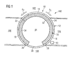
- a security area 100 of an aircraft is shown in each of Figures 1 to 14 .
- the security area 100 comprises a first area 102, constructed in the form of a cockpit, a second area 104, constructed as a washroom or toilet, a third area 106 likewise constructed as a washroom or toilet, and a fourth area 108 formed by a passenger cabin.
- the four areas 102, 104, 106, 108 are connected to one another by a security door 10.
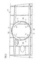
- the security door 10 comprises a frame structure 12 with a substantially hollow cylindrical basic shape, in the lateral surface of which a plurality of doorways 14, 16, 18, 20 is constructed, see in particular Figure 3 .
- a first doorway 14 constructed in the lateral surface of the frame structure 12 serves to connect the security door 10 to the first area 102 constructed in the form of a cockpit.
- a second doorway 16 constructed in the lateral surface of the frame structure 12 serves to connect the security door 10 to the second area 104 constructed as a washroom or toilet.
- a third doorway 18 constructed in the lateral surface of the frame structure 12 serves to connect the security door 10 to the third area 106 constructed as a washroom or toilet.
- a fourth doorway 18 constructed in the lateral surface of the frame structure 12 serves to connect the security door 10 to the fourth area 108 formed by a passenger cabin.
- all the doorways 14, 16, 18, 20 have the same width, which corresponds to a required minimum doorway width in an aircraft.
- the fourth doorway 20 located opposite the first doorway 14 is delimited in the first direction R 1 and the second direction R 2 along the inner circumference of the frame structure 12 by lateral surface portions 26, 28, which are not provided with a doorway and whereof the width along the inner circumference of the frame structure 12 is considerably smaller than the width of the doorways 14, 16, 18, 20 and the lateral surface portions 22, 24 delimiting the first doorway 14.
- the security door further comprises a lock element 30 received in the frame structure 12.
- the lock element 30 comprises a first segment 32, which is movable along the inner circumference of the frame structure 12 relative to the frame structure 12, and a second segment 34, which is movable independently of the first segment 32 along the inner circumference of the frame structure relative to the frame structure, see Figures 1 and 4 to 7 .
- the first and the second segment 32, 34 of the lock element 30 are dimensioned so that, in a position in which they open any doorway 14, 16, 18, 20 constructed in the lateral surface of the frame structure 12, they close all other doorways 14, 16, 18, 20 constructed in the lateral surface of the frame structure 12.
- the first segment 32 of the lock element 30 is dimensioned so that, in a first position shown in Figure 1 , in which it closes the first doorway 14, it also closes a second doorway 16 adjacent to the first doorway 14 in the first direction R 1 along the inner circumference of the frame structure 12.
- the second segment 34 of the lock element 30 is dimensioned so that, in the first position shown in Figure 1 , in which the second segment 34 in the second direction R 2 along the inner circumference of the frame structure 12 is immediately adjacent to the first segment 32 closing the first doorway 14, it is able to close the third doorway 18, which is adjacent to the first doorway 14 in the second direction R 2 along the inner circumference of the frame structure 12.
- edge regions 36, 38 of the segments 30, 32 are provided with complementary cutouts 40, 42 to enable the edge regions 36, 38 to overlap along the inner circumference of the frame structure 12.
- the security door further comprises a control device 43 which serves to control the movement of the segments 32, 34 of the lock element 30 relative to the frame structure 12 independently of one another according to predetermined control regulations for access to areas 102, 104, 106, 108 adjoining the security door 10.
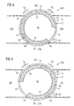
- the predetermined control regulations specify how the movement of the segments 32, 34 has to take place if the fourth doorway 20 is opened first, see Figure 1 , and then the second or third doorway 16, 18 are to be opened, see Figures 4 and 5 .
- the predetermined control regulations further specify how the movement of the segments 32, 34 has to take place if the fourth doorway 20 is opened first and then the first doorway 14 is to be opened. It is necessary to control the movement of the segments 32, 34 of the lock element 30 in this way if a person is to be allowed to enter the lock chamber 44 of the security door 10 from the fourth area 108, which adjoins the fourth doorway 20 and is constructed in the form of a passenger cabin, and then to exit the lock chamber 44 of the security door 10 through the first doorway 14 into the first area 102, which adjoins the first doorway and is constructed in the form of a cockpit, see Figures 6 and 7 .
- the control regulations are stored in a memory of the control device 43.
- the control device 43 controls the movement of the segments 32, 34 of the lock element 30 relative to the frame structure 12 in such a way that the segments 32, 34 are moved together relative to the frame structure 12 from the first position shown in Figure 1 , in which the segments 32, 34 open the fourth doorway 20, in the second direction R 2 along the inner circumference of the frame structure 12 into a second position shown in Figure 4 , in which the segments 32, 34 open the second doorway 16.
- the control device 43 further controls the movement of the segments 32, 34 of the lock element 30 relative to the frame structure 12 in such a way that the segments 32, 34 are moved together relative to the frame structure 12 from the first position according to Figure 1 in the first direction R 1 along the inner circumference of the frame structure 12 into a third position shown in Figure 5 , in which the segments 32, 34 open the third doorway 18.
- the control device 43 controls the movement of the segments 32, 34 of the lock element 30 relative to the frame structure 12 in such a way that the segments 32, 34 are moved together relative to the frame structure 12 from a fourth position shown in Figure 6 , in which the segments 32, 34 open the first doorway 14, in the first direction R 1 along the inner circumference of the frame structure 12 into the second position (see Figure 4 ), in which the segments 32, 34 open the second doorway 16.
- control device 43 can control the movement of the segments 32, 34 of the lock element 30 relative to the frame structure 12 in such a way that the segments 32, 34 are moved together relative to the frame structure 12 from the fourth position according to Figure 6 , in which the segments 32, 34 open the first doorway 14, in the second direction R 2 along the inner circumference of the frame structure 12 into the third position (see Figure 5 ), in which the segments 32, 34 open the third doorway 18.
- the control device 43 of the security door 10 After a person has entered the lock chamber 44 from one of the areas 104, 106, 108 through the second, the third or the fourth doorway 16, 18, 20, the control device 43 of the security door 10 provides for the lock chamber 44 to be sealed off completely before the first doorway 14 is opened.
- control device 43 controls the movement of the segments 32, 34 of the lock element 30 relative to the frame structure 12 in such a way that, starting from the first position according to Figure 1 , in which the segments 32, 34 open the fourth doorway 20, the second position according to Figure 4 , in which the segments 32, 34 open the second doorway 16, and/or the third position according to Figure 5 , in which segments 32, 34 open the third doorway 18, the segments 32, 34 are moved relative to the frame structure 12 along the inner circumference of the frame structure 12 into a fifth position shown in Figure 7 , in which the segments 32, 34 close all the doorways 14, 16, 18, 20 constructed in the lateral surface of the frame structure 12.
- the movement of the segments 32, 34 of the lock element 30 relative to the frame structure 12 is controlled by the control device 43 in such a way that, starting from the first position according to Figure 1 , in which the segments 32, 34 open the fourth doorway 20, the second segment 34 is moved relative to the frame structure 12 and the first segment 32 in the second direction R 2 along the inner circumference of the frame structure 12 into the fifth position according to Figure 7 , in which the segments 32, 34 close all the doorways 14, 16, 18, 20 constructed in the lateral surface of the frame structure 12.
- the segments 32, 34 can then be moved together, i.e. at the same time and in the same direction, relative to the frame structure 12 from the fifth position according to Figure 7 in the first direction R 1 along the inner circumference of the frame structure 12 into the fourth position according to Figure 6 , in which the segments 32, 34 open the first doorway 14.
- the movement of the segments 32, 34 of the lock element 30 relative to the frame structure 12 can be controlled by the control device 43 in such a way that, starting from the second position according to Figure 4 , in which the segments 32, 34 open the second doorway 16, the first segment 32 is moved relative to the frame structure 12 and the second segment 34 in the first direction R 1 along the inner circumference of the frame structure 12 into the fifth position according to Figure 7 , in which the segments 32, 34 close all the doorways 14, 16, 18, 20 constructed in the lateral surface of the frame structure 12.
- the segments 32, 34 can then be moved together relative to the frame structure 12 from the fifth position according to Figure 7 in the first direction R 1 along the inner circumference of the frame structure 12 into the fourth position according to Figure 6 , in which the segments 32, 34 open the first doorway 14.
- the movement of the segments 32, 34 of the lock element 30 relative to the frame structure 12 is likewise controlled by the control device 43 in such a way that the first segment 32 is moved relative to the frame structure 12 and the second segment 34 in the first direction R 1 along the inner circumference of the frame structure 12 into a position (not shown in the Figures) in which the first segment 32 adjoins the second segment 34 in the region of an edge of the third doorway 18 which faces the first doorway 14 and the segments 32, 34 close all the doorways 14, 16, 18, 20 constructed in the lateral surface of the frame structure 12.
- the segments 32, 34 can then be moved together relative to the frame structure 12 in the second direction R 2 along the inner circumference of the frame structure 12 into the fourth position according to Figure 6 , in which the segments 32, 34 open the first doorway 14.
- the first segment 32 of the lock element 30 comprises a first segment portion 32a, which is movable along the inner circumference of the frame structure 12 relative to the frame structure 12, and a second segment portion 32b, which is movable independently of the first segment portion 32a along the inner circumference of the frame structure 12 relative to the frame structure 12.
- the first segment portion 32a of the first segment 32 is dimensioned so that, when positioned accordingly relative to the frame structure 12, it can close any doorway 14, 16, 18, 20.
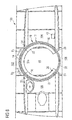
- the segments 32, 34 of the lock element 30 are located in their first position shown in Figure 8 , in which they open the fourth doorway 20, the first segment portion 32a of the first segment 32 extends along the inner circumference of the frame structure 12 over the first doorway 14 and adjoins the second segment 34 in the second direction R 2 along the inner circumference of the frame structure 12.
- the movement of the segments 32, 34 relative to the frame structure 12 in the case of a lock element 30 with a two-piece first segment 32 is also controlled by the control device 43 in such a way that the segments 32, 34, and therefore also the segment portions 32a, 32b of the first segment 32, are moved together relative to the frame structure 12 from a first position according to Figure 8 , in which the segments 32, 34 open the fourth doorway 20, in the second direction R 2 along the inner circumference of the frame structure 12 into a second position shown in Figure 9 , in which the segments 32, 34 open the second doorway 16.
- the movement of the segments 32, 34 of the lock element 30 relative to the frame structure 12 is further controlled in such a way that the segments 32, 34 and therefore also the segment portions 32a, 32b of the first segment 30 are moved together relative to the frame structure 12 from the first position according to Figure 8 , in which the segments 32, 34 open the fourth doorway 20, in the first direction R 1 along the inner circumference of the frame structure 12 into a third position shown in Figure 10 , in which the segments 32, 34 open the third doorway 18.
- the movement of the segments 32, 34 of the lock element 30 relative to the frame structure 12 is further controlled by the control device 43 in such a way that the segments 32, 34 and therefore also the segment portions 32a, 32b of the first segment 32 are moved together relative to the frame structure 12 from a fourth position, shown in figure 11 , in which the segments 32, 34 open the first doorway 14, in the first direction R 1 along the inner circumference of the frame structure 12 into the second position according to Figure 9 , in which the segments 32, 34 open the second doorway 16.
- the movement of the segments 32, 34 of the lock element 30 relative to the frame structure 12 is finally controlled in such a way that the segments 32, 34 and therefore also the segment portions 32a, 32b of the first segment 32 are moved together relative to the frame structure 12 from a fourth position according to Figure 11 , in which the segments 32, 34 open the first doorway 14, in the second direction R 2 along the inner circumference of the frame structure 12 into the third position according to Figure 10 , in which the segments 32, 34 open the third doorway 18.
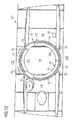
- the control device 43 moreover controls the movement of the segments 32, 34 of the lock element 30 and the segment portions 32a, 32b of the first segment 32 relative to the frame structure 12 in such a way that, starting from the first position according to Figure 8 , in which the segments 32, 34 open the fourth doorway 20, the segments 32, 34 are moved relative to the frame structure 12 along the inner circumference of the frame structure 12 into a sixth position shown in Figure 12 , in which the segments 32, 34 close all the doorways 14, 16, 18, 20 constructed in the lateral surface of the frame structure 12.
- the control device 43 then controls the movement of the segments 32, 34 in such a way that the segments 32, 34 are moved from the sixth position according to Figure 12 along the inner circumference of the frame structure 12 into the fourth position according to Figure 11 , in which the segments 32, 34 open the first doorway 14.
- the control device 43 of the security door 10 again provides for the lock chamber 44 to be sealed off completely before the first doorway 14 is opened.
- the movement of the first and the second segment 32a, 32b of the lock element 32 relative to the frame structure 12 is controlled by the control device 43 in such a way that, starting from the first position according to Figure 8 , in which the segments 32, 34 open the fourth doorway 20, the second segment 34 is moved relative to the frame structure 12 and the first segment portion 32a of the first segment 32 in the second direction R 2 along the inner circumference of the frame structure 12.
- the control device 43 further controls a movement of the second segment portion 32b of the first segment 32 relative to the frame structure 12 and the first segment portion 32a of the first segment 32 in the first direction R 1 along the inner circumference of the frame structure 12 into the sixth position according to Figure 12 , in which the segments 32, 34 close all the doorways 14, 16, 18, 20 constructed in the lateral surface of the frame structure 12.
- the first segment portion 32a of the first segment 32 remains in its position, whilst the second segment portion 32b of the first segment 32 and the second segment 34 move in opposite directions along the inner circumference of the frame structure 12 until all the doorways 14, 16, 18, 20 constructed in the lateral surface of the frame structure 12 are closed.
- the control device 43 controls a movement of the first segment portion 32a of the first segment 32 relative to the frame structure 12, the second segment 34 and the second segment portion 32a of the first segment 32 in the second direction R 2 along the inner circumference of the frame structure 12 into an intermediate position according to Figure 13 , in which the first segment portion 32a of the first segment 32 adjoins the second segment 34.
- the segments 32, 34 are then moved together relative to the frame structure 12 from the intermediate position according to Figure 13 in the second direction R 2 along the inner circumference of the frame structure 12 into the fourth position according to Figure 11 , in which the segments 32, 34 open the first doorway 14.
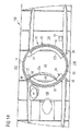
- the security door 10 further comprises a swivel arrangement 46 which enables a swivel movement of the first segment portion 32a of the first segment 32 relative to the frame structure 12 and the second segment portion 32b of the first segment 32 in the direction of the lock area 44 of the security door 10. If the segments 32, 34 of the lock element 30 open the fourth doorway 20, the first doorway 14 can be opened at the same time by swivelling the first segment portion 32a of the first segment 32 relative to the frame structure 12 and the second segment portion 32b of the first segment 32 in the direction of the lock area 44 of the security door 10.
- This constellation is not usually desirable in normal operation of the security door but, in an emergency situation, for example in the event of a fire in the first area 102 adjoining the first doorway 14, it enables two fire fighters carrying an extinguishing hose to gain access to the first area 102.
- the security door 10 further comprises a locking mechanism 48 (merely indicated schematically in Figure 14 ) which, in an unlocking position, enables a swivel movement of the first segment portion 32a of the first segment 32 relative to the frame structure 12 in the direction of the lock area 44 and, in a locking position, prevents a swivel movement of the first segment portion 32a of the first segment 32 relative to the frame structure 12 in the direction of the lock area 44.
- the locking mechanism 48 is controlled electronically and only assumes its unlocking position upon a corresponding signal which indicates that the aircraft is on the ground and an emergency situation has arisen in the first area 102.
Landscapes
- Engineering & Computer Science (AREA)
- Aviation & Aerospace Engineering (AREA)
- Mechanical Engineering (AREA)
- Civil Engineering (AREA)
- Structural Engineering (AREA)
- Power-Operated Mechanisms For Wings (AREA)
- Residential Or Office Buildings (AREA)
- Wing Frames And Configurations (AREA)
Abstract
Description
- The invention relates to a security door, which is particularly suitable for use in a vehicle. The invention further relates to a security area equipped with a security door of this type, in particular a security area of a vehicle, which is equipped with a security door of this type.
- The cockpit area on board modern commercial aircraft is subject to particular security regulations. It is particularly necessary to prevent unauthorised persons from gaining entry to the cockpit. A lock system for controlling access to a cockpit is known from
DE 102 04 544 B4 orUS 6,925,756 B2 . This lock system comprises a substantially hollow-cylindrically shaped frame structure in the lateral surface of which a plurality of doorways are constructed. A likewise substantially hollow cylindrical bell-shaped lock is rotatably received in the frame structure. Likewise constructed in a lateral surface of the bell-shaped lock is a doorway which, through a corresponding rotation of the bell-shaped lock relative to the frame structure, can be moved so that it is congruent with one of the doorways constructed in the frame-structure opening to enable entry into an internal area of the lock system, which is delimited by the bell-shaped lock, or to enable exit from the internal area of the lock system, which is delimited by the bell-shaped lock. - The invention is based on the object of providing a security door which is optimised in terms of its installation space and which enables effective access control for areas adjoining the security door. The invention is furthermore based on the object of providing a security area equipped with a security door of this type.
- This object is achieved by a security door having the features of Claim 1 and a security area having the features of
Claim 14. - A security door according to the invention has a frame structure in the lateral surface of which a plurality of doorways is constructed. The frame structure can have, for example, a substantially hollow cylindrical basic shape. A first doorway constructed in the lateral surface of the frame structure has a first width along an inner circumference of the frame structure. If the security door is to be used on board an aircraft, for example in the area of a cockpit, the first width of the first doorway can correspond for example to a required minimum doorway width in an aircraft. The first doorway can serve for example to connect the security door to a cockpit. Lateral surface portions, which delimit the first doorway in a first direction and a second direction, opposed to the first direction, along the inner circumference of the frame structure and are not provided with a doorway, have a second width which can be smaller than, equal to, or greater than the width of the first doorway. It is essentially conceivable to construct the lateral surface portions delimiting the first doorway along the inner circumference of the frame structure with different widths. However, these lateral surface portions preferably have the same width along the inner circumference of the frame structure, with the width of the lateral surface portions corresponding in particular substantially to the first width of the first doorway.
- The security door further comprises a lock element received in the frame structure. The lock element comprises a first segment, which is movable along the inner circumference of the frame structure relative to the frame structure, and a second segment which is movable independently of the first segment along the inner circumference of the frame structure relative to the frame structure. Segments which are "movable independently of one another" refer here to segments which, as required, can be moved together or relative to one another in the same direction or in opposite directions along the inner circumference of the frame structure. The first and the second segment of the lock element are preferably dimensioned so that, in a position in which they open a doorway constructed in the lateral surface of the frame structure, they close all other doorways constructed in the lateral surface of the frame structure. This can be achieved for example by a design of the segments of the lock element in which, in a position in which they open a doorway constructed in the lateral surface of the frame structure, the segments extend along the entire remainder of the inner circumference of the frame structure.
- The first segment of the lock element is dimensioned so that, in a position in which it closes the first doorway, it also closes a second doorway which is adjacent to the first doorway in the first direction along the inner circumference of the frame structure. The second doorway can serve for example to grant a person situated in the double-door area of the security door access to a service area, for example a washroom or toilet. As a result of the inventive design of the lock element, it can be ensured that a maximum of one doorway is opened when the movement of the segments of the lock element relative to the frame structure is controlled accordingly. In particular, it is possible to prevent the segments of the lock element from arriving in a position in which they partially or completely open the first and the second doorway at the same time. A person entering a lock area, which is delimited by the frame structure and the segments of the lock element, through a doorway then only gains access to one of the areas connected to the security door after entering the lock area. This enables effective access control for the areas adjoining the security door. At the same time, the inventive design of the lock element enables the installation space of the security door to be optimised since, even with small diameters of the lock area, it is possible to realise an adequate doorway width without encountering the problem of two mutually adjacent doorways being partially or completely opened at the same time.
- In a preferred embodiment of the security door according to the invention, the second segment of the lock element is dimensioned so that, in a position in which the second segment in the second direction along the inner circumference of the frame structure is immediately adjacent to the first segment closing the first doorway, it is able to close a third doorway adjacent to the first doorway in the second direction along the inner circumference of the frame structure. The third doorway can serve to grant a person situated in the lock area of the security door access to a further service area, for example a washroom or a toilet. If the first segment is positioned relative to the frame structure in such a way that, although the first segment closes the first doorway, it does not extend substantially beyond the first doorway in the second direction along the inner circumference of the frame structure, the second segment then extends along the lateral surface portion delimiting the first doorway in the second direction along the inner circumference of the frame structure and subsequently further over the third doorway.
- It is possible to construct a fourth doorway, which is opposite the first doorway, in the lateral surface of the frame structure. If the security door according to the invention is provided for use in a commercial aircraft, a fourth doorway can serve to connect the lock area of the security door to a passenger cabin of the aircraft. A third width of the fourth doorway along the inner circumference of the frame structure preferably corresponds to the first width of the first doorway. Lateral surface portions delimiting the fourth doorway in the first direction and the second direction along the inner circumference of the frame structure can have a fourth width which is smaller than the third width of the fourth doorway. All of the doorways constructed in the lateral surface of the frame structure preferably have a width corresponding to the first width of the first doorway. The fourth width of the lateral surface portions delimiting the fourth doorway along the inner circumference of the frame structure is preferably considerably smaller than the second width of the lateral surface portions delimiting the first doorway along the inner circumference of the frame structure and, in particular, is dimensioned to be small enough for the dimensions of the second segment to be sufficient for closing the fourth and the second or the fourth and the third doorway at the same time when suitably positioned relative to the frame structure.
- The security door preferably comprises a control device which is designed to control the movement of the segments of the lock element relative to the frame structure independently of one another according to predefined control regulations for access to areas adjoining the security door. The predefined control regulations can specify for example how the movement of the segments should take place if the fourth doorway is opened first and the second or the third doorway are then to be opened. It may be necessary to control the movement of the segments of the lock element in this way for example if a person is to be granted access to the lock chamber of the security door from a passenger cabin adjoining the fourth doorway and to then be allowed to exit from the lock chamber of the security door through the second or the third doorway into a washroom adjoining the second or the third doorway.
- The predefined control regulations can further specify how the movement of the segments should take place if the fourth doorway is opened first and then the first doorway is to be opened. It may be necessary to control the movement of the segments of the lock element in this way for example if a person is to be allowed to enter the lock chamber of the security door from a passenger cabin adjoining the fourth doorway and then to exit from the lock chamber of the security door through the first doorway into a cockpit adjoining the first doorway. It goes without saying that different control regulations can apply for different movements of the segments, for example depending on particular security requirements. The control regulations according to which the control device controls the movement of the segments of the lock element relative to the frame structure can be stored in a memory of the control device.
- The control device is preferably designed to control the movement of the segments of the lock element relative to the frame structure in such a way that the segments are moved together, i.e. at the same time and in the same direction, relative to the frame structure from a first position, in which the segments open the fourth doorway, in the second direction along the inner circumference of the frame structure into a second position, in which the segments open the second doorway. Alternatively or in addition to this, the control device can be designed to control the movement of the segments of the lock element relative to the frame structure in such a way that the segments are moved together, i.e. at the same time and in the same direction, relative to the frame structure from a first position, in which the segments open the fourth doorway, in the first direction along the inner circumference of the frame structure into a third position, in which the segments open the third doorway.
- The control device can further be designed to control the movement of the segments of the lock element relative to the frame structure in such a way that the segments are moved together, i.e. at the same time and in the same direction, relative to the frame structure from a fourth position, in which the segments open the first doorway, in the first direction along the inner circumference of the frame structure into the second position, in which the segments open the second doorway. Alternatively or in addition to this, the control device can be designed to control the movement of the segments of the lock element relative to the frame structure in such a way that the segments are moved together, i.e. at the same time and in the same direction, relative to the frame structure from a fourth position, in which the segments open the first doorway, in the second direction along the inner circumference of the frame structure into the third position, in which the segments open the third doorway.
- When the security door according to the invention is used in an aircraft, the control regulations of the control device can then specify a common movement (i.e. at the same time and in the same direction) of the segments of the lock element relative to the frame structure if a person is to be allowed to enter the lock chamber of the security door from a passenger cabin adjoining the fourth doorway and then to exit the lock chamber of the security door through the second or third doorway into a washroom adjoining the second or third doorway. In similar manner, the control regulations of the control device can specify a common movement (i.e. at the same time and in the same direction) of the segments of the lock element relative to the frame structure if a person is to be allowed to enter the lock chamber of the security door from a cockpit adjoining the first doorway and then to exit the lock chamber of the security door through the second or third doorway into a washroom adjoining the second or third doorway.
- The control device can further be designed to control the movement of the segments of the lock element relative to the frame structure in such a way that, starting from the first position, in which the segments open the fourth doorway, the second position, in which segments open the second doorway, and/or the third position, in which the segments open the third doorway, the segments are moved relative to the frame structure along the inner circumference of the frame structure into a fifth position, in which the segments close all of the doorways constructed in the lateral surface of the frame structure. When the security door according to the invention is used in an aircraft, provision can therefore be made to seal off the lock chamber completely after a person has entered the lock chamber from the passenger cabin or a washroom via the second, the third or the fourth doorway.
- The control device can further be designed to control the movement of the segments of the lock element relative to the frame structure in such a way that the segments are then moved from the fifth position along the inner circumference of the frame structure into the fourth position, in which the segments open the first doorway. When the security door according to the invention is used in an aircraft, the access to the cockpit can be opened by this movement of the segments. The control device can be designed to control the movement of the segments of the lock element relative to the frame structure starting from the fifth position, in which the segments close all of the doorways constructed in the lateral surface of the frame structure, according to a suitable opening signal. The opening signal can be issued for example as a reaction to inputting an access code.
- The control device can be designed for example to control the movement of the segments of the lock element relative to the frame structure in such a way that, starting from the first position, in which the segments open the fourth doorway, the second segment is moved relative to the frame structure and the first segment in the second direction along the inner circumference of the frame structure into the fifth position, in which the segments close all the doorways constructed in the lateral surface of the frame structure. The segments can then be moved together, i.e. at the same time and in the same direction, relative to the frame structure from the fifth position in the first direction along the inner circumference of the frame structure into the fourth position, in which the segments open the first doorway.
- In a preferred embodiment of the security door, the first segment of the lock element comprises a first segment portion, which can be moved along the inner circumference of the frame structure relative to the frame structure, and a second segment portion which can be moved independently of the first segment portion along the inner circumference of the frame structure relative to the frame structure. Segment portions which are "movable independently of one another" refer here to segment portions which, as required, can be moved together or relative to one another in the same direction or in opposite directions along the inner circumference of the frame structure. The first segment portion of the first segment is preferably dimensioned so that, when the first segment portion is positioned accordingly relative to the frame structure, it is able to close the first doorway. If all doorways have the same width, when the first segment portion is positioned accordingly relative to the frame structure, the first segment portion of the first segment is preferably able to close each doorway. If the segments of the lock element are located in their first position, in which they open the fourth doorway, the first segment portion of the first segment extends along the inner circumference of the frame structure over the first doorway and adjoins the second segment in the second direction along the inner circumference of the frame structure.
- Also in an embodiment of the first segment with two segment portions, the control device is preferably designed to control the movement of the segments of the lock element relative to the frame structure in such a way that the segments and therefore also the segment portions of the first segment are moved together, i.e. at the same time and in the same direction, relative to the frame structure from a first position, in which the segments open the fourth doorway, in the second direction along the inner circumference of the frame structure into a second position, in which the segments open the second doorway. Alternatively or in addition to this, the control device can be designed to control the movement of the segments of the lock element relative to the frame structure in such a way that the segments and therefore also the segment portions of the first segment are moved together, i.e. at the same time and in the same direction, relative to the frame structure from a first position, in which the segments open the fourth doorway, in the first direction along the inner circumference of the frame structure into a third position, in which the segments open the third doorway.
- The control device can further be designed to control the movement of the segments of the lock element relative to the frame structure in such a way that the segments and therefore also the segment portions of the first segment are moved together, i.e. at the same time and in the same direction, relative to the frame structure from a fourth position, in which the segments open the first doorway, in the first direction along the inner circumference of the frame structure into the second position, in which the segments open the second doorway. Alternatively or in addition to this, the control device can be designed to control the movement of the segments of the lock element relative to the frame structure in such a way that the segments and therefore also the segment portions of the first segment are moved together, i.e. at the same time and in the same direction, relative to the frame structure from a fourth position, in which the segments open the first doorway, in the second direction along the inner circumference of the frame structure into the third position, in which the segments open the third doorway.
- The control device can moreover be designed to control the movement of the segments of the lock element and the segment portions of the first segment relative to the frame structure in such a way that, starting from the first position, in which the segments open the fourth doorway, the segments are moved relative to the frame structure along the inner circumference of the frame structure into a sixth position, in which the segments close all the doorways constructed in the lateral surface of the frame structure. The sixth position, which a first segment comprising two segment portions and a second segment assume in order to close all the doorways constructed in the lateral surface of the frame structure, can differ from the fifth position described above, which a first segment constructed as one piece and a second segment assume in order to close all the doorways constructed in the lateral surface of the frame structure. The control device can further control the movement of the segments in such a way that the segments are then moved from the sixth position along the inner circumference of the frame structure into the fourth position, in which the segments open the first doorway. The fourth position, which a first segment comprising two segment portions and a second segment assume in order to open the first doorway, preferably corresponds to the fourth position described above, which a first segment constructed in one piece and a second segment assume in order to open the first doorway.
- The control device can further be designed to control the movement of the first and the second segment of the lock element relative to the frame structure in such a way that, starting from the first position, in which the segments open the fourth doorway, the second segment is moved relative to the frame structure and the first segment portion of the first segment in the second direction along the inner circumference of the frame structure. The control device can further control a movement of the second segment portion of the first segment relative to the frame structure and the first segment portion of the first segment in the first direction along the inner circumference of the frame structure into the sixth position, in which the segments close all the doorways constructed in the lateral surface of the frame structure. In other words, the first segment portion of the first segment remains in its position whilst the second segment portion of the first segment and the second segment move in opposite directions along the inner circumference of the frame structure until all the doorways constructed in the lateral surface of the frame structure are closed.
- The control device can further be designed to then initiate a movement of the first segment portion of the first segment relative to the frame structure, the second segment and the second segment portion of the first segment in the second direction along the inner circumference of the frame structure into an intermediate position, in which the first segment portion of the first segment adjoins the second segment. Finally, the control device can be designed to then induce a common movement (i.e. at the same time and in the same direction) of the segments relative to the frame structure from the intermediate position in the second direction along the inner circumference of the frame structure into the fourth position, in which the segments open the first doorway.
- The security door can further comprise a swivel arrangement which is designed to enable a swivel movement of the first segment portion of the first segment relative to the frame structure and the second segment portion of the first segment in the direction of an internal area of the frame structure, i.e. in the direction of the lock area of the security door. If the segments of the lock element are located in the first position, in which they open the fourth doorway, the first doorway can be opened at the same time by swivelling the first segment portion of the first segment relative to the frame structure and the second segment portion of the first segment in the direction of the lock area of the security door. It goes without saying that this constellation is not usually desirable in normal operation of the security door. In an emergency, for example in the event of a fire in the area adjoining the first doorway, for example in a cockpit, two fire fighters carrying a extinguishing hose can be granted access to the area adjoining the first doorway.
- To counteract misuse of the swivel arrangement, the security door can further comprise a locking mechanism which, in an unlocking position, is designed to permit a swivel movement of the first segment portion of the first segment relative to the frame structure in the direction of the internal area of the frame structure and, in a locking position, to prevent a swivel movement of the first segment portion of the first segment relative to the frame structure in the direction of the internal area of the frame structure. The locking mechanism can be controlled electronically for example, and only assume its unlocking position upon a corresponding signal which indicates for example that the aircraft is on the ground and there is an emergency situation in the cockpit.
- Mutually adjacent edge regions of the segments and/or segment portions can preferably be provided with complementary cutouts to enable the edge regions to overlap along the inner circumference of the frame structure. This enables a bulletproof construction of the edge regions.
- A security area according to the invention comprises a security door, described above, and a plurality of areas adjoining the security door, which are connected to one another by the security door. The area adjoining the first doorway of the security door can be for example a cockpit of an aircraft. The areas adjoining the second and the third doorway of the security door can be for example service areas, for example washrooms or toilets. The area adjoining the fourth doorway of the security door can be for example a passenger cabin of an aircraft.
- Preferred embodiments of the invention are now explained in more detail with reference to the accompanying schematic drawings, which show:
- Figure 1
- an aircraft security area equipped with a first embodiment of a security door, wherein segments of a lock element of the security door are located in a first position,
- Figure 2
- a detailed illustration of the edge region of the segments of the lock element according to
Figure 1 , - Figure 3
- a frame structure of the security door according to
Figure 1 , - Figure 4
- the aircraft security area according to
Figure 1 , wherein segments of a lock element of the security door are located in a second position, - Figure 5
- the aircraft security area according to
Figure 1 , wherein segments of a lock element of the security door are located in a third position, - Figure 6
- the aircraft security area according to
Figure 1 , wherein segments of a lock element of the security door are located in a fourth position, - Figure 7
- the aircraft security area according to
Figure 1 , wherein segments of a lock element of the security door are located in a fifth position, - Figure 8
- an aircraft security area equipped with a second embodiment of a security door, wherein segments of a lock element of the security door are located in a first position,
- Figure 9
- the aircraft security area according to
Figure 8 , wherein segments of a lock element of the security door are located in a second position, - Figure 10
- the aircraft security area according to
Figure 8 , wherein segments of a lock element of the security door are located in a third position, - Figure 11
- the aircraft security area according to
Figure 8 , wherein segments of a lock element of the security door are located in a fourth position, - Figure 12
- the aircraft security area according to
Figure 8 , wherein segments of a lock element of the security door are located in a fifth position, - Figure 13
- the aircraft security area according to
Figure 8 , wherein segments of a lock element of the security door are located in an intermediate position, and - Figure 14
- the aircraft security area according to
Figure 8 , wherein a first segment portion of a first segment of the lock element is swivelled relative to the second segment portion of the first segment, a second segment and the frame structure. - A
security area 100 of an aircraft is shown in each ofFigures 1 to 14 . Thesecurity area 100 comprises afirst area 102, constructed in the form of a cockpit, asecond area 104, constructed as a washroom or toilet, athird area 106 likewise constructed as a washroom or toilet, and afourth area 108 formed by a passenger cabin. The fourareas security door 10. - The
security door 10 comprises aframe structure 12 with a substantially hollow cylindrical basic shape, in the lateral surface of which a plurality ofdoorways Figure 3 . Afirst doorway 14 constructed in the lateral surface of theframe structure 12 serves to connect thesecurity door 10 to thefirst area 102 constructed in the form of a cockpit. Asecond doorway 16 constructed in the lateral surface of theframe structure 12 serves to connect thesecurity door 10 to thesecond area 104 constructed as a washroom or toilet. Athird doorway 18 constructed in the lateral surface of theframe structure 12 serves to connect thesecurity door 10 to thethird area 106 constructed as a washroom or toilet. Finally, afourth doorway 18 constructed in the lateral surface of theframe structure 12 serves to connect thesecurity door 10 to thefourth area 108 formed by a passenger cabin. As seen along the inner circumference of theframe structure 12, all thedoorways -
Lateral surface portions first doorway 14 in a first direction R1 and a second direction R2, which is opposed to the first direction R1, along the inner circumference of theframe structure 12 and are not provided with a doorway, have a width which corresponds substantially to the width of thefirst doorway 14. However, it is also conceivable to select the width of thelateral surface portions first doorway 14. Thefourth doorway 20 located opposite thefirst doorway 14 is delimited in the first direction R1 and the second direction R2 along the inner circumference of theframe structure 12 bylateral surface portions frame structure 12 is considerably smaller than the width of thedoorways lateral surface portions first doorway 14. - The security door further comprises a
lock element 30 received in theframe structure 12. Thelock element 30 comprises afirst segment 32, which is movable along the inner circumference of theframe structure 12 relative to theframe structure 12, and asecond segment 34, which is movable independently of thefirst segment 32 along the inner circumference of the frame structure relative to the frame structure, seeFigures 1 and4 to 7 . The first and thesecond segment lock element 30 are dimensioned so that, in a position in which they open anydoorway frame structure 12, they close allother doorways frame structure 12. Thefirst segment 32 of thelock element 30 is dimensioned so that, in a first position shown inFigure 1 , in which it closes thefirst doorway 14, it also closes asecond doorway 16 adjacent to thefirst doorway 14 in the first direction R1 along the inner circumference of theframe structure 12. - The
second segment 34 of thelock element 30 is dimensioned so that, in the first position shown inFigure 1 , in which thesecond segment 34 in the second direction R2 along the inner circumference of theframe structure 12 is immediately adjacent to thefirst segment 32 closing thefirst doorway 14, it is able to close thethird doorway 18, which is adjacent to thefirst doorway 14 in the second direction R2 along the inner circumference of theframe structure 12. In the first position shown inFigure 1 , in which thefirst segment 32 is positioned relative to theframe structure 12 in such a way that, although thefirst segment 32 closes thefirst doorway 14, it does not extend substantially beyond thefirst doorway 14 in the second direction R2 along the inner circumference of theframe structure 12, thesecond segment 34 then extends along thelateral surface portion 22 delimiting thefirst doorway 12 in the second direction R2 along the inner circumference of theframe structure 12 and subsequently further over thethird doorway 18. - As can be seen in
Figure 2 , mutually adjacent edge regions 36, 38 of thesegments complementary cutouts frame structure 12. - The security door further comprises a
control device 43 which serves to control the movement of thesegments lock element 30 relative to theframe structure 12 independently of one another according to predetermined control regulations for access toareas security door 10. The predetermined control regulations specify how the movement of thesegments fourth doorway 20 is opened first, seeFigure 1 , and then the second orthird doorway Figures 4 and 5 . It is necessary to control the movement of thesegments lock element 30 in this way if a person is to be allowed to enter alock chamber 44 of thesecurity door 10 from thearea 108, which adjoins thefourth doorway 20 and is constructed in the form of a passenger cabin, and then to exit thelock chamber 44 of thesecurity door 10 through the second orthird doorway third area third doorway - The predetermined control regulations further specify how the movement of the
segments fourth doorway 20 is opened first and then thefirst doorway 14 is to be opened. It is necessary to control the movement of thesegments lock element 30 in this way if a person is to be allowed to enter thelock chamber 44 of thesecurity door 10 from thefourth area 108, which adjoins thefourth doorway 20 and is constructed in the form of a passenger cabin, and then to exit thelock chamber 44 of thesecurity door 10 through thefirst doorway 14 into thefirst area 102, which adjoins the first doorway and is constructed in the form of a cockpit, seeFigures 6 and 7 . The control regulations are stored in a memory of thecontrol device 43. - If a person is to be allowed to enter the
lock chamber 44 of thesecurity door 10 from thefourth area 108, which adjoins thefourth doorway 20 and is constructed in the form of a passenger cabin, and then to exit thelock chamber 44 of thesecurity door 10 through the second orthird doorway third area third doorway control device 43 controls the movement of thesegments lock element 30 relative to theframe structure 12 in such a way that thesegments frame structure 12 from the first position shown inFigure 1 , in which thesegments fourth doorway 20, in the second direction R2 along the inner circumference of theframe structure 12 into a second position shown inFigure 4 , in which thesegments second doorway 16. Thecontrol device 43 further controls the movement of thesegments lock element 30 relative to theframe structure 12 in such a way that thesegments frame structure 12 from the first position according toFigure 1 in the first direction R1 along the inner circumference of theframe structure 12 into a third position shown inFigure 5 , in which thesegments third doorway 18. - If a person is to be allowed to enter the
lock chamber 44 of thesecurity door 10 from thefirst area 102, which adjoins the first doorway and is constructed in the form of a cockpit, and then to exit thelock chamber 44 of thesecurity door 10 through the second orthird doorway third area third doorway control device 43 controls the movement of thesegments lock element 30 relative to theframe structure 12 in such a way that thesegments frame structure 12 from a fourth position shown inFigure 6 , in which thesegments first doorway 14, in the first direction R1 along the inner circumference of theframe structure 12 into the second position (seeFigure 4 ), in which thesegments second doorway 16. Alternatively to this, thecontrol device 43 can control the movement of thesegments lock element 30 relative to theframe structure 12 in such a way that thesegments frame structure 12 from the fourth position according toFigure 6 , in which thesegments first doorway 14, in the second direction R2 along the inner circumference of theframe structure 12 into the third position (seeFigure 5 ), in which thesegments third doorway 18. - After a person has entered the
lock chamber 44 from one of theareas fourth doorway control device 43 of thesecurity door 10 provides for thelock chamber 44 to be sealed off completely before thefirst doorway 14 is opened. In particular, thecontrol device 43 controls the movement of thesegments lock element 30 relative to theframe structure 12 in such a way that, starting from the first position according toFigure 1 , in which thesegments fourth doorway 20, the second position according toFigure 4 , in which thesegments second doorway 16, and/or the third position according toFigure 5 , in whichsegments third doorway 18, thesegments frame structure 12 along the inner circumference of theframe structure 12 into a fifth position shown inFigure 7 , in which thesegments doorways frame structure 12. Only then is the movement of thesegments lock element 30 relative to theframe structure 12 controlled by thecontrol device 43 in such a way that thesegments Figure 7 along the inner circumference of theframe structure 12 into the fourth position (seeFigure 6 ) in which thesegments first doorway 14. Thecontrol device 43 controls the movement of thesegments lock element 30 relative to theframe structure 12 starting from the fifth position according toFigure 7 , in which thesegments doorways frame structure 12, according to a suitable opening signal, which is issued for example as a reaction to inputting an access code at thecontrol device 43. - The movement of the
segments lock element 30 relative to theframe structure 12 is controlled by thecontrol device 43 in such a way that, starting from the first position according toFigure 1 , in which thesegments fourth doorway 20, thesecond segment 34 is moved relative to theframe structure 12 and thefirst segment 32 in the second direction R2 along the inner circumference of theframe structure 12 into the fifth position according toFigure 7 , in which thesegments doorways frame structure 12. Thesegments frame structure 12 from the fifth position according toFigure 7 in the first direction R1 along the inner circumference of theframe structure 12 into the fourth position according toFigure 6 , in which thesegments first doorway 14. - In similar manner, the movement of the
segments lock element 30 relative to theframe structure 12 can be controlled by thecontrol device 43 in such a way that, starting from the second position according toFigure 4 , in which thesegments second doorway 16, thefirst segment 32 is moved relative to theframe structure 12 and thesecond segment 34 in the first direction R1 along the inner circumference of theframe structure 12 into the fifth position according toFigure 7 , in which thesegments doorways frame structure 12. Thesegments frame structure 12 from the fifth position according toFigure 7 in the first direction R1 along the inner circumference of theframe structure 12 into the fourth position according toFigure 6 , in which thesegments first doorway 14. - Starting from the third position according to
Figure 5 , in which thesegments third doorway 18, the movement of thesegments lock element 30 relative to theframe structure 12 is likewise controlled by thecontrol device 43 in such a way that thefirst segment 32 is moved relative to theframe structure 12 and thesecond segment 34 in the first direction R1 along the inner circumference of theframe structure 12 into a position (not shown in the Figures) in which thefirst segment 32 adjoins thesecond segment 34 in the region of an edge of thethird doorway 18 which faces thefirst doorway 14 and thesegments doorways frame structure 12. Thesegments frame structure 12 in the second direction R2 along the inner circumference of theframe structure 12 into the fourth position according toFigure 6 , in which thesegments first doorway 14. - In an embodiment of the
security door 10 which is shown inFigures 8 to 14 , thefirst segment 32 of thelock element 30 comprises afirst segment portion 32a, which is movable along the inner circumference of theframe structure 12 relative to theframe structure 12, and asecond segment portion 32b, which is movable independently of thefirst segment portion 32a along the inner circumference of theframe structure 12 relative to theframe structure 12. Thefirst segment portion 32a of thefirst segment 32 is dimensioned so that, when positioned accordingly relative to theframe structure 12, it can close anydoorway segments lock element 30 are located in their first position shown inFigure 8 , in which they open thefourth doorway 20, thefirst segment portion 32a of thefirst segment 32 extends along the inner circumference of theframe structure 12 over thefirst doorway 14 and adjoins thesecond segment 34 in the second direction R2 along the inner circumference of theframe structure 12. - As explained above in connection with a
lock element 30 with a single-piecefirst segment 32, the movement of thesegments frame structure 12 in the case of alock element 30 with a two-piecefirst segment 32 is also controlled by thecontrol device 43 in such a way that thesegments segment portions first segment 32, are moved together relative to theframe structure 12 from a first position according toFigure 8 , in which thesegments fourth doorway 20, in the second direction R2 along the inner circumference of theframe structure 12 into a second position shown inFigure 9 , in which thesegments second doorway 16. The movement of thesegments lock element 30 relative to theframe structure 12 is further controlled in such a way that thesegments segment portions first segment 30 are moved together relative to theframe structure 12 from the first position according toFigure 8 , in which thesegments fourth doorway 20, in the first direction R1 along the inner circumference of theframe structure 12 into a third position shown inFigure 10 , in which thesegments third doorway 18. - The movement of the
segments lock element 30 relative to theframe structure 12 is further controlled by thecontrol device 43 in such a way that thesegments segment portions first segment 32 are moved together relative to theframe structure 12 from a fourth position, shown infigure 11 , in which thesegments first doorway 14, in the first direction R1 along the inner circumference of theframe structure 12 into the second position according toFigure 9 , in which thesegments second doorway 16. The movement of thesegments lock element 30 relative to theframe structure 12 is finally controlled in such a way that thesegments segment portions first segment 32 are moved together relative to theframe structure 12 from a fourth position according toFigure 11 , in which thesegments first doorway 14, in the second direction R2 along the inner circumference of theframe structure 12 into the third position according toFigure 10 , in which thesegments third doorway 18. - The
control device 43 moreover controls the movement of thesegments lock element 30 and thesegment portions first segment 32 relative to theframe structure 12 in such a way that, starting from the first position according toFigure 8 , in which thesegments fourth doorway 20, thesegments frame structure 12 along the inner circumference of theframe structure 12 into a sixth position shown inFigure 12 , in which thesegments doorways frame structure 12. Thecontrol device 43 then controls the movement of thesegments segments Figure 12 along the inner circumference of theframe structure 12 into the fourth position according toFigure 11 , in which thesegments first doorway 14. After a person has entered thelock chamber 44 from one of theareas fourth doorway control device 43 of thesecurity door 10 again provides for thelock chamber 44 to be sealed off completely before thefirst doorway 14 is opened. - The movement of the first and the
second segment lock element 32 relative to theframe structure 12 is controlled by thecontrol device 43 in such a way that, starting from the first position according toFigure 8 , in which thesegments fourth doorway 20, thesecond segment 34 is moved relative to theframe structure 12 and thefirst segment portion 32a of thefirst segment 32 in the second direction R2 along the inner circumference of theframe structure 12. Thecontrol device 43 further controls a movement of thesecond segment portion 32b of thefirst segment 32 relative to theframe structure 12 and thefirst segment portion 32a of thefirst segment 32 in the first direction R1 along the inner circumference of theframe structure 12 into the sixth position according toFigure 12 , in which thesegments doorways frame structure 12. In other words, thefirst segment portion 32a of thefirst segment 32 remains in its position, whilst thesecond segment portion 32b of thefirst segment 32 and thesecond segment 34 move in opposite directions along the inner circumference of theframe structure 12 until all thedoorways frame structure 12 are closed. - Starting from the second position according to
Figure 9 , in which thesegments second doorway 16, or the third position according toFigure 10 , in which thesegments third doorway 18, the movement of thesegments security door 10 having a single-piecefirst segment 32, can be controlled to move the segments into the fifth position shown inFigure 7 , in which thesegments doorways frame structure 12. - In order to open the
first doorway 14, starting from the sixth position according toFigure 12 , in which thesegments doorways frame structure 12, thecontrol device 43 controls a movement of thefirst segment portion 32a of thefirst segment 32 relative to theframe structure 12, thesecond segment 34 and thesecond segment portion 32a of thefirst segment 32 in the second direction R2 along the inner circumference of theframe structure 12 into an intermediate position according toFigure 13 , in which thefirst segment portion 32a of thefirst segment 32 adjoins thesecond segment 34. Thesegments frame structure 12 from the intermediate position according toFigure 13 in the second direction R2 along the inner circumference of theframe structure 12 into the fourth position according toFigure 11 , in which thesegments first doorway 14. - As can be seen in
Figure 14 , thesecurity door 10 further comprises aswivel arrangement 46 which enables a swivel movement of thefirst segment portion 32a of thefirst segment 32 relative to theframe structure 12 and thesecond segment portion 32b of thefirst segment 32 in the direction of thelock area 44 of thesecurity door 10. If thesegments lock element 30 open thefourth doorway 20, thefirst doorway 14 can be opened at the same time by swivelling thefirst segment portion 32a of thefirst segment 32 relative to theframe structure 12 and thesecond segment portion 32b of thefirst segment 32 in the direction of thelock area 44 of thesecurity door 10. This constellation is not usually desirable in normal operation of the security door but, in an emergency situation, for example in the event of a fire in thefirst area 102 adjoining thefirst doorway 14, it enables two fire fighters carrying an extinguishing hose to gain access to thefirst area 102. - To counteract misuse of the
swivel arrangement 46, thesecurity door 10 further comprises a locking mechanism 48 (merely indicated schematically inFigure 14 ) which, in an unlocking position, enables a swivel movement of thefirst segment portion 32a of thefirst segment 32 relative to theframe structure 12 in the direction of thelock area 44 and, in a locking position, prevents a swivel movement of thefirst segment portion 32a of thefirst segment 32 relative to theframe structure 12 in the direction of thelock area 44. Thelocking mechanism 48 is controlled electronically and only assumes its unlocking position upon a corresponding signal which indicates that the aircraft is on the ground and an emergency situation has arisen in thefirst area 102.
Claims (15)
- A security door (10) having:- a frame structure (12) in the lateral surface of which a plurality of doorways (14, 16, 18, 20) is constructed, wherein a first doorway (14) constructed in the lateral surface of the frame structure (12) has a first width along an inner circumference of the frame structure (12), and wherein lateral surface portions (22, 24) delimiting the first doorway (14) in a first direction (R1) and a second direction (R2), opposing the first direction (R1), along the inner circumference of the frame structure (12) have a second width, and- a lock element (30) received in the frame structure (12),
characterised in that the lock element (30) comprises a first segment (32), which is movable along the inner circumference of the frame structure (12) relative to the frame structure (12), and a second segment (34), which is movable independently of the first segment (32) along the inner circumference of the frame structure (12) relative to the frame structure (12), wherein the first segment (32) of the lock element (30) is dimensioned so that, in a position in which it closes the first doorway (14), it also closes a second doorway (16) adjacent to the first doorway (14) in the first direction (R1) along the inner circumference of the frame structure (12). - A security door according to Claim 1,
characterised in that the second segment (34) of the lock element (30) is dimensioned so that, in a position in which the second segment (34) in the second direction (R2) along the inner circumference of the frame structure (12) is immediately adjacent to the first segment (32) closing the first doorway (14, it is able to close a third doorway (18) adjacent to the first doorway (14) in the second direction (R2) along the inner circumference of the frame structure (12). - A security door according to Claim 1 or 2,
characterised in that a fourth doorway (20) opposite the first doorway (14) is constructed in the lateral surface of the frame structure (12), wherein a third width of the fourth doorway (20) along the inner circumference of the frame structure (12) corresponds in particular to the first width of the first doorway (14), and wherein lateral surface portions (26, 28) delimiting the fourth doorway (20) in the first direction (R1) and the second direction (R2) along the inner circumference of the frame structure (12) have a fourth width which is smaller than the third width of the fourth doorway (20). - A security door according to one of Claims 1 to 3,
characterised by a control device (43) which is designed to control the movement of the segments (32, 34) of the lock element (30) relative to the frame structure (12) independently of one another according to predetermined control regulations for access to areas (102, 104, 106, 108) adjoining the security door (10). - A security door according to Claim 4,
characterised in that the control device (43) is designed to control the movement of the segments (32, 34) of the lock element (30) relative to the frame structure (12) as follows:- moving the segments (32, 34) together relative to the frame structure (12) from a first position, in which the segments (32, 34) open the fourth doorway (20), in the second direction (R2) along the inner circumference of the frame structure (12) into a second position, in which the segments (32, 34) open the first doorway (16),
and/or- moving the segments (32, 34) together relative to the frame structure (12), from a first position, in which the segments (32, 34) open the fourth doorway (20), in the first direction (R1) along the inner circumference of the frame structure (12) into a third position, in which the segments (32, 34) open the doorway (18). - A security door according to Claim 4 or 5,
characterised in that the control device (43) is designed to control the movement of the segments (32, 34) of the lock element (30) relative to the frame structure (12) as follows:- moving the segments (32, 34) together relative to the frame structure (12) from a fourth position, in which the segments (32, 34) open the first doorway (14), in the first direction (R1) along the inner circumference of the frame structure (12) into the second position, in which the segments (32, 34) open the first doorway (16),
and/or- moving the segments (32, 34) together relative to the frame structure (12), from a fourth position, in which the segments (32, 34) open the first doorway (14), in the second direction (R2) along the inner circumference of the frame structure (12) into the third position, in which the segments (32, 34) open the third doorway (18). - A security door according to one of Claims 4 to 6,
characterised in that the control device (43) is designed to control the movement of the segments (32, 34) of the lock element (30) relative to the frame structure (12) in such a way that, starting from the first position, in which the segments (32, 34) open the fourth doorway (20), the second position, in which the segments open the second doorway, and/or the third position, in which the segments open the third doorway, the segments (32, 34) are moved relative to the frame structure (12) along the inner circumference of the frame structure (12) into a fifth position, in which the segments (32, 34) close all the doorways (14, 16, 18, 20) constructed in the lateral surface of the frame structure, and in that the segments (32, 34) are then moved from the fifth position along the inner circumference of the frame structure (12) into the fourth position, in which the segments (32, 34) open the first doorway (14). - A security door according to one of Claims 4 to 7,
characterised in that the control device (43) is designed to control the movement of the segments (32, 34) of the lock element (30) relative to the frame structure (12) as follows:- starting from the first position, in which the segments (32, 34) open the first doorway (20), moving the second segment (34) relative to the frame structure (12) and the first segment (32) in the second direction (R2) along the inner circumference of the frame structure (12) into the fifth position, in which the segments (32, 34) close all the doorways (14, 16, 18, 20) constructed in the lateral surface of the frame structure, and- then moving the segments (32, 34) together relative to the frame structure (12) from the fifth position in the first direction (R1) along the inner circumference of the frame structure (12) into the fourth position, in which the segments (32, 34) open the first doorway (14). - A security door according to one of Claims 1 to 8,
characterised in that the first segment (32) of the lock element (30) comprises a first segment portion (32a), which is movable along the inner circumference of the frame structure (12) relative to the frame structure (12), and a second segment portion (32b), which is movable independently of the first segment portion (32a) along the inner circumference of the frame structure (12) relative to the frame structure (12), wherein the first segment portion (32a) of the first segment (32) is dimensioned so that, when the first segment portion (32a) is in a corresponding position relative to the frame structure (12), it is able to close the first doorway (14). - A security door according to Claim 9,
characterised in that the control device (43) is designed to control the movement of the segments (32, 34) of the lock element (30) and the segment portions (32a, 32b) of the first segment (32) relative to the frame structure (12) in such a way that, starting from the first position, in which the segments (32, 34) open the fourth doorway (20), the segments (32, 34) are moved relative to the frame structure (12) along the inner circumference of the frame structure (12) into a sixth position, in which the segments (32, 34) close all the doorways (14, 16, 18, 20) constructed in the lateral surface of the frame structure, and in that the segments (32, 34) are then moved from the sixth position along the inner circumference of the frame structure (12) into the fourth position, in which the segments (32, 34) open the first doorway (14). - A security door according to Claim 9 or 10,
characterised in that the control device (43) is designed to control the movement of the first and the second segment (32, 34) of the lock element relative to the frame structure (12) as follows:- starting from the first position, in which the segments (32, 34) open the fourth doorway (20), moving the second segment (34) relative to the frame structure (12) and the first segment portion (32a) of the first segment (32) in the second direction (R2) along the inner circumference of the frame structure (12) and moving the second segment portion (32b) of the first segment (32) relative to the frame structure (12) and the first segment portion (32a) of the first segment (32) in the first direction (R1) along the inner circumference of the frame structure (12) into the sixth position, in which the segments (32, 34) close all the doorways (14, 16, 18, 20) constructed in the lateral surface of the frame structure,- then moving the first segment portion (32a) of the first segment (32) relative to the frame structure (12), the second segment (34) and the second segment portion (32b) of the first segment (32) in the second direction (R2) along the inner circumference of the frame structure (12) into an intermediate position, in which the first segment portion (32a) of the first segment (32) adjoins the second segment (34), and- then moving the segments (32, 34) together relative to the frame structure (12) from the intermediate position in the second direction (R2) along the inner circumference of the frame structure (12) into the fourth position, in which the segments (32, 34) open the first doorway (14). - A security door according to one of Claims 9 to 11,
characterised by a swivel arrangement (46) which is designed to enable a swivel movement of the first segment portion (32a) of the first segment (32) relative to the frame structure (12) and the second segment portion (32b) of the first segment (32) in the direction of an internal area of the frame structure (12). - A security door according to Claim 12,
characterised by a locking mechanism (48) which is designed such that, in an unlocking position, it permits a swivel movement of the first segment portion (32a) of the first segment (32) relative to the frame structure (12) in the direction of the internal area of the frame structure (12) and, in a locking position, it prevents a swivel movement of the first segment portion (32a) of the first segment (32) relative to the frame structure (12) in the direction of the frame structure (12). - A security door according to one of Claims 1 to 13,
characterised in that mutually adjacent edge regions (36, 38) of the segments (32, 34) and/or segment portions (32a, 32b) are provided with complementary cutouts (40, 42) to enable the edge regions (36, 38) to overlap along the inner circumference of the frame structure (12). - A security area (100), in particular an aircraft security area, having:- a security door (10) according to one of Claims 1 to 12,- a plurality of areas (102, 104, 106, 108) adjoining the security door (10), which are connected to one another by the security door (10).
Applications Claiming Priority (2)
| Application Number | Priority Date | Filing Date | Title |
|---|---|---|---|
| US201261720003P | 2012-10-30 | 2012-10-30 | |
| DE102012021432.4A DE102012021432A1 (en) | 2012-10-30 | 2012-10-30 | Security door and security area |
Publications (3)
| Publication Number | Publication Date |
|---|---|
| EP2727823A2 true EP2727823A2 (en) | 2014-05-07 |
| EP2727823A3 EP2727823A3 (en) | 2016-10-12 |
| EP2727823B1 EP2727823B1 (en) | 2018-10-10 |
Family
ID=49509971
Family Applications (1)
| Application Number | Title | Priority Date | Filing Date |
|---|---|---|---|
| EP13190566.3A Not-in-force EP2727823B1 (en) | 2012-10-30 | 2013-10-29 | Security door and security area |
Country Status (4)
| Country | Link |
|---|---|
| US (1) | US9073619B2 (en) |
| EP (1) | EP2727823B1 (en) |
| CN (1) | CN103790494B (en) |
| DE (1) | DE102012021432A1 (en) |
Cited By (3)
| Publication number | Priority date | Publication date | Assignee | Title |
|---|---|---|---|---|
| FR3036098A1 (en) * | 2015-05-12 | 2016-11-18 | Airbus Operations Sas | FOLDING WALL ACCESS DEVICE FOR SECURE COMMUNICATION BETWEEN AT LEAST TWO ZONES OF AN ENCLOSURE |
| FR3036097A1 (en) * | 2015-05-12 | 2016-11-18 | Airbus Operations Sas | ACCESS DEVICE WITH INDEPENDENT MOBILE WALLS FOR SECURE COMMUNICATION BETWEEN AT LEAST TWO ZONES OF AN ENCLOSURE |
| EP3099575B1 (en) * | 2014-01-30 | 2021-05-26 | Airbus Operations GmbH | Aircraft interior door assembly |
Families Citing this family (1)
| Publication number | Priority date | Publication date | Assignee | Title |
|---|---|---|---|---|
| GB2579068A (en) * | 2018-11-16 | 2020-06-10 | Ford Global Tech Llc | Vehicle access structure |
Citations (1)
| Publication number | Priority date | Publication date | Assignee | Title |
|---|---|---|---|---|
| DE10204544B4 (en) | 2002-02-05 | 2004-04-01 | Airbus Deutschland Gmbh | Access device to the driver's cab of a means of transport, in particular to the cockpit of a commercial aircraft |
Family Cites Families (17)
| Publication number | Priority date | Publication date | Assignee | Title |
|---|---|---|---|---|
| GB1223699A (en) * | 1968-04-29 | 1971-03-03 | British Europ Airways Corp | Improvements in revolving doors |
| US3658277A (en) * | 1970-12-11 | 1972-04-25 | Charles I Anderson | Aircraft anti-hijacking structure |
| IT1222561B (en) | 1987-08-28 | 1990-09-05 | Tonali Spa | BUSH FOR SAFETY INPUTS OF BANKS AND SIMILAR |
| IT1255955B (en) * | 1992-11-26 | 1995-11-17 | SAFETY COMPASS FOR BANKS AND SIMILAR | |
| DE69424627T2 (en) * | 1993-11-16 | 2001-02-08 | Kimura Industry Co., Ltd. | Door for toilet |
| FR2781248B1 (en) * | 1998-07-20 | 2000-09-15 | Pentagon Management Ltd | DRUM DOOR WHOSE LATERAL WALLS IN A CIRCLE OF CIRCLE ARE MOBILE TO AUTHORIZE THE CROSSING OF SEVERAL FLOWS WITHOUT MIXING OF THE DIFFERENT ELEMENTS CONSTITUTING THE FLOWS |
| DE19932153C1 (en) * | 1999-07-12 | 2000-11-23 | Dorma Gmbh & Co Kg | Sliding door assembly at a building entry/exit has side sections and sliding door panels with at least one swing air blower for ventilation between the building interior and exterior which is coupled to an external wind gauge |
| DE19937364B4 (en) * | 1999-08-12 | 2004-09-09 | Dorma Gmbh + Co. Kg | revolving door |
| NL1016700C2 (en) * | 2000-11-24 | 2002-05-27 | Boon Edam Bv | Hinged door for installation in a facade of a building. |
| US6601797B2 (en) * | 2001-10-26 | 2003-08-05 | David Sheremeta | Rotating cockpit door |
| JP3771527B2 (en) * | 2002-03-29 | 2006-04-26 | ナブテスコ株式会社 | Door equipment |
| DE10318159A1 (en) | 2003-04-17 | 2004-11-25 | Dorma Gmbh + Co. Kg | revolving door |
| NL1026300C1 (en) * | 2004-06-01 | 2005-12-05 | Petrus Johannes Wilhelmus Herp | Access control device. |
| US7249737B2 (en) | 2004-07-28 | 2007-07-31 | David Simmons | Cell door system for aircraft security |
| DE102005032168A1 (en) * | 2005-07-09 | 2007-01-18 | Dorma Gmbh + Co. Kg | Circular sliding doors for entry and exit, include individually-controlled doors operated by linear drives in diverse modes ranging from airlock to escape |
| FR2965793B1 (en) * | 2010-10-08 | 2013-06-14 | Airbus Operations Sas | SAS SECURE ACCESS TO COCKPIT OF AN AIRCRAFT AND AIRCRAFT EQUIPPED WITH SUCH A SAS ACCESS |
| EP2692980A1 (en) * | 2012-07-31 | 2014-02-05 | Airbus Operations GmbH | Apparatus for controlling access to restricted zone |
-
2012
- 2012-10-30 DE DE102012021432.4A patent/DE102012021432A1/en not_active Withdrawn
-
2013
- 2013-10-29 EP EP13190566.3A patent/EP2727823B1/en not_active Not-in-force
- 2013-10-29 US US14/065,671 patent/US9073619B2/en active Active
- 2013-10-30 CN CN201310527054.9A patent/CN103790494B/en not_active Expired - Fee Related
Patent Citations (2)
| Publication number | Priority date | Publication date | Assignee | Title |
|---|---|---|---|---|
| DE10204544B4 (en) | 2002-02-05 | 2004-04-01 | Airbus Deutschland Gmbh | Access device to the driver's cab of a means of transport, in particular to the cockpit of a commercial aircraft |
| US6925756B2 (en) | 2002-02-05 | 2005-08-09 | Airbus Deutschland Gmbh | Apparatus for controlling the ingress and egress to and from an operator's compartment |
Cited By (5)
| Publication number | Priority date | Publication date | Assignee | Title |
|---|---|---|---|---|
| EP3099575B1 (en) * | 2014-01-30 | 2021-05-26 | Airbus Operations GmbH | Aircraft interior door assembly |
| FR3036098A1 (en) * | 2015-05-12 | 2016-11-18 | Airbus Operations Sas | FOLDING WALL ACCESS DEVICE FOR SECURE COMMUNICATION BETWEEN AT LEAST TWO ZONES OF AN ENCLOSURE |
| FR3036097A1 (en) * | 2015-05-12 | 2016-11-18 | Airbus Operations Sas | ACCESS DEVICE WITH INDEPENDENT MOBILE WALLS FOR SECURE COMMUNICATION BETWEEN AT LEAST TWO ZONES OF AN ENCLOSURE |
| US9944380B2 (en) | 2015-05-12 | 2018-04-17 | Airbus Operations S.A.S. | Access device provided with independent mobile walls enabling secure communication between at least two zones of an enclosure |
| US10392096B2 (en) | 2015-05-12 | 2019-08-27 | Airbus Operations S.A.S. | Access device provided with a folding door enabling secure communication between at least two zones of an enclosure |
Also Published As
| Publication number | Publication date |
|---|---|
| CN103790494B (en) | 2017-01-18 |
| EP2727823B1 (en) | 2018-10-10 |
| US9073619B2 (en) | 2015-07-07 |
| EP2727823A3 (en) | 2016-10-12 |
| DE102012021432A1 (en) | 2014-04-30 |
| US20140115966A1 (en) | 2014-05-01 |
| CN103790494A (en) | 2014-05-14 |
Similar Documents
| Publication | Publication Date | Title |
|---|---|---|
| US11279461B2 (en) | Flight deck barrier door, aircraft comprising flight deck barrier door, and method of using flight deck barrier door | |
| US10392096B2 (en) | Access device provided with a folding door enabling secure communication between at least two zones of an enclosure | |
| US7984875B2 (en) | Multi-position secure door system | |
| US8672267B2 (en) | Toilet arrangement for a vehicle | |
| CN103153785B (en) | Aircraft cockpit safe access door lock and the aircraft being furnished with this access door lock | |
| JP4955550B2 (en) | Door that closes the opening inside the aircraft | |
| US9944380B2 (en) | Access device provided with independent mobile walls enabling secure communication between at least two zones of an enclosure | |
| EP4406829B1 (en) | Aircraft section and aircraft having a monument with two lavatories | |
| US9073619B2 (en) | Security door and security area | |
| US20230415897A1 (en) | Flexible aircraft privacy door | |
| EP4011781B1 (en) | Cockpit door security system | |
| EP2692980A1 (en) | Apparatus for controlling access to restricted zone | |
| US10343779B2 (en) | Aircraft interior door assembly | |
| US10220933B2 (en) | Flight deck door assembly | |
| US20240417075A1 (en) | Dual Purpose Lavatory Barrier | |
| US20030136878A1 (en) | Method and apparatus for impeding unauthorized entry into the cockpit of an airplane | |
| EP4442563B1 (en) | Telescoping secondary barrier system | |
| JP4840877B2 (en) | Aircraft interior security door |
Legal Events
| Date | Code | Title | Description |
|---|---|---|---|
| PUAI | Public reference made under article 153(3) epc to a published international application that has entered the european phase |
Free format text: ORIGINAL CODE: 0009012 |
|
| 17P | Request for examination filed |
Effective date: 20131029 |
|
| AK | Designated contracting states |
Kind code of ref document: A2 Designated state(s): AL AT BE BG CH CY CZ DE DK EE ES FI FR GB GR HR HU IE IS IT LI LT LU LV MC MK MT NL NO PL PT RO RS SE SI SK SM TR |
|
| AX | Request for extension of the european patent |
Extension state: BA ME |
|
| PUAL | Search report despatched |
Free format text: ORIGINAL CODE: 0009013 |
|
| AK | Designated contracting states |
Kind code of ref document: A3 Designated state(s): AL AT BE BG CH CY CZ DE DK EE ES FI FR GB GR HR HU IE IS IT LI LT LU LV MC MK MT NL NO PL PT RO RS SE SI SK SM TR |
|
| AX | Request for extension of the european patent |
Extension state: BA ME |
|
| RIC1 | Information provided on ipc code assigned before grant |
Ipc: B64C 1/14 20060101AFI20160902BHEP Ipc: B64D 45/00 20060101ALI20160902BHEP |
|
| STAA | Information on the status of an ep patent application or granted ep patent |
Free format text: STATUS: EXAMINATION IS IN PROGRESS |
|
| 17Q | First examination report despatched |
Effective date: 20170508 |
|
| GRAP | Despatch of communication of intention to grant a patent |
Free format text: ORIGINAL CODE: EPIDOSNIGR1 |
|
| STAA | Information on the status of an ep patent application or granted ep patent |
Free format text: STATUS: GRANT OF PATENT IS INTENDED |
|
| INTG | Intention to grant announced |
Effective date: 20180530 |
|
| GRAS | Grant fee paid |
Free format text: ORIGINAL CODE: EPIDOSNIGR3 |
|
| GRAA | (expected) grant |
Free format text: ORIGINAL CODE: 0009210 |
|
| STAA | Information on the status of an ep patent application or granted ep patent |
Free format text: STATUS: THE PATENT HAS BEEN GRANTED |
|
| AK | Designated contracting states |
Kind code of ref document: B1 Designated state(s): AL AT BE BG CH CY CZ DE DK EE ES FI FR GB GR HR HU IE IS IT LI LT LU LV MC MK MT NL NO PL PT RO RS SE SI SK SM TR |
|
| REG | Reference to a national code |
Ref country code: GB Ref legal event code: FG4D |
|
| REG | Reference to a national code |
Ref country code: CH Ref legal event code: EP Ref country code: AT Ref legal event code: REF Ref document number: 1050911 Country of ref document: AT Kind code of ref document: T Effective date: 20181015 |
|
| REG | Reference to a national code |
Ref country code: FR Ref legal event code: PLFP Year of fee payment: 6 |
|
| REG | Reference to a national code |
Ref country code: IE Ref legal event code: FG4D |
|
| REG | Reference to a national code |
Ref country code: DE Ref legal event code: R096 Ref document number: 602013044778 Country of ref document: DE |
|
| REG | Reference to a national code |
Ref country code: NL Ref legal event code: MP Effective date: 20181010 |
|
| REG | Reference to a national code |
Ref country code: LT Ref legal event code: MG4D |
|
| REG | Reference to a national code |
Ref country code: AT Ref legal event code: MK05 Ref document number: 1050911 Country of ref document: AT Kind code of ref document: T Effective date: 20181010 |
|
| PG25 | Lapsed in a contracting state [announced via postgrant information from national office to epo] |
Ref country code: NL Free format text: LAPSE BECAUSE OF FAILURE TO SUBMIT A TRANSLATION OF THE DESCRIPTION OR TO PAY THE FEE WITHIN THE PRESCRIBED TIME-LIMIT Effective date: 20181010 |
|
| PG25 | Lapsed in a contracting state [announced via postgrant information from national office to epo] |
Ref country code: NO Free format text: LAPSE BECAUSE OF FAILURE TO SUBMIT A TRANSLATION OF THE DESCRIPTION OR TO PAY THE FEE WITHIN THE PRESCRIBED TIME-LIMIT Effective date: 20190110 Ref country code: LT Free format text: LAPSE BECAUSE OF FAILURE TO SUBMIT A TRANSLATION OF THE DESCRIPTION OR TO PAY THE FEE WITHIN THE PRESCRIBED TIME-LIMIT Effective date: 20181010 Ref country code: HR Free format text: LAPSE BECAUSE OF FAILURE TO SUBMIT A TRANSLATION OF THE DESCRIPTION OR TO PAY THE FEE WITHIN THE PRESCRIBED TIME-LIMIT Effective date: 20181010 Ref country code: PL Free format text: LAPSE BECAUSE OF FAILURE TO SUBMIT A TRANSLATION OF THE DESCRIPTION OR TO PAY THE FEE WITHIN THE PRESCRIBED TIME-LIMIT Effective date: 20181010 Ref country code: LV Free format text: LAPSE BECAUSE OF FAILURE TO SUBMIT A TRANSLATION OF THE DESCRIPTION OR TO PAY THE FEE WITHIN THE PRESCRIBED TIME-LIMIT Effective date: 20181010 Ref country code: IS Free format text: LAPSE BECAUSE OF FAILURE TO SUBMIT A TRANSLATION OF THE DESCRIPTION OR TO PAY THE FEE WITHIN THE PRESCRIBED TIME-LIMIT Effective date: 20190210 Ref country code: BG Free format text: LAPSE BECAUSE OF FAILURE TO SUBMIT A TRANSLATION OF THE DESCRIPTION OR TO PAY THE FEE WITHIN THE PRESCRIBED TIME-LIMIT Effective date: 20190110 Ref country code: ES Free format text: LAPSE BECAUSE OF FAILURE TO SUBMIT A TRANSLATION OF THE DESCRIPTION OR TO PAY THE FEE WITHIN THE PRESCRIBED TIME-LIMIT Effective date: 20181010 Ref country code: FI Free format text: LAPSE BECAUSE OF FAILURE TO SUBMIT A TRANSLATION OF THE DESCRIPTION OR TO PAY THE FEE WITHIN THE PRESCRIBED TIME-LIMIT Effective date: 20181010 Ref country code: AT Free format text: LAPSE BECAUSE OF FAILURE TO SUBMIT A TRANSLATION OF THE DESCRIPTION OR TO PAY THE FEE WITHIN THE PRESCRIBED TIME-LIMIT Effective date: 20181010 |
|
| PG25 | Lapsed in a contracting state [announced via postgrant information from national office to epo] |
Ref country code: GR Free format text: LAPSE BECAUSE OF FAILURE TO SUBMIT A TRANSLATION OF THE DESCRIPTION OR TO PAY THE FEE WITHIN THE PRESCRIBED TIME-LIMIT Effective date: 20190111 Ref country code: RS Free format text: LAPSE BECAUSE OF FAILURE TO SUBMIT A TRANSLATION OF THE DESCRIPTION OR TO PAY THE FEE WITHIN THE PRESCRIBED TIME-LIMIT Effective date: 20181010 Ref country code: AL Free format text: LAPSE BECAUSE OF FAILURE TO SUBMIT A TRANSLATION OF THE DESCRIPTION OR TO PAY THE FEE WITHIN THE PRESCRIBED TIME-LIMIT Effective date: 20181010 Ref country code: SE Free format text: LAPSE BECAUSE OF FAILURE TO SUBMIT A TRANSLATION OF THE DESCRIPTION OR TO PAY THE FEE WITHIN THE PRESCRIBED TIME-LIMIT Effective date: 20181010 Ref country code: PT Free format text: LAPSE BECAUSE OF FAILURE TO SUBMIT A TRANSLATION OF THE DESCRIPTION OR TO PAY THE FEE WITHIN THE PRESCRIBED TIME-LIMIT Effective date: 20190210 |
|
| REG | Reference to a national code |
Ref country code: CH Ref legal event code: PL |
|
| REG | Reference to a national code |
Ref country code: BE Ref legal event code: MM Effective date: 20181031 |
|
| PG25 | Lapsed in a contracting state [announced via postgrant information from national office to epo] |
Ref country code: LU Free format text: LAPSE BECAUSE OF NON-PAYMENT OF DUE FEES Effective date: 20181029 |
|
| REG | Reference to a national code |
Ref country code: DE Ref legal event code: R097 Ref document number: 602013044778 Country of ref document: DE |
|
| REG | Reference to a national code |
Ref country code: IE Ref legal event code: MM4A |
|
| PG25 | Lapsed in a contracting state [announced via postgrant information from national office to epo] |
Ref country code: IT Free format text: LAPSE BECAUSE OF FAILURE TO SUBMIT A TRANSLATION OF THE DESCRIPTION OR TO PAY THE FEE WITHIN THE PRESCRIBED TIME-LIMIT Effective date: 20181010 Ref country code: DK Free format text: LAPSE BECAUSE OF FAILURE TO SUBMIT A TRANSLATION OF THE DESCRIPTION OR TO PAY THE FEE WITHIN THE PRESCRIBED TIME-LIMIT Effective date: 20181010 Ref country code: CZ Free format text: LAPSE BECAUSE OF FAILURE TO SUBMIT A TRANSLATION OF THE DESCRIPTION OR TO PAY THE FEE WITHIN THE PRESCRIBED TIME-LIMIT Effective date: 20181010 |
|
| PLBE | No opposition filed within time limit |
Free format text: ORIGINAL CODE: 0009261 |
|
| STAA | Information on the status of an ep patent application or granted ep patent |
Free format text: STATUS: NO OPPOSITION FILED WITHIN TIME LIMIT |
|
| PG25 | Lapsed in a contracting state [announced via postgrant information from national office to epo] |
Ref country code: LI Free format text: LAPSE BECAUSE OF NON-PAYMENT OF DUE FEES Effective date: 20181031 Ref country code: MC Free format text: LAPSE BECAUSE OF FAILURE TO SUBMIT A TRANSLATION OF THE DESCRIPTION OR TO PAY THE FEE WITHIN THE PRESCRIBED TIME-LIMIT Effective date: 20181010 Ref country code: CH Free format text: LAPSE BECAUSE OF NON-PAYMENT OF DUE FEES Effective date: 20181031 Ref country code: SM Free format text: LAPSE BECAUSE OF FAILURE TO SUBMIT A TRANSLATION OF THE DESCRIPTION OR TO PAY THE FEE WITHIN THE PRESCRIBED TIME-LIMIT Effective date: 20181010 Ref country code: BE Free format text: LAPSE BECAUSE OF NON-PAYMENT OF DUE FEES Effective date: 20181031 Ref country code: SK Free format text: LAPSE BECAUSE OF FAILURE TO SUBMIT A TRANSLATION OF THE DESCRIPTION OR TO PAY THE FEE WITHIN THE PRESCRIBED TIME-LIMIT Effective date: 20181010 Ref country code: RO Free format text: LAPSE BECAUSE OF FAILURE TO SUBMIT A TRANSLATION OF THE DESCRIPTION OR TO PAY THE FEE WITHIN THE PRESCRIBED TIME-LIMIT Effective date: 20181010 Ref country code: EE Free format text: LAPSE BECAUSE OF FAILURE TO SUBMIT A TRANSLATION OF THE DESCRIPTION OR TO PAY THE FEE WITHIN THE PRESCRIBED TIME-LIMIT Effective date: 20181010 |
|
| 26N | No opposition filed |
Effective date: 20190711 |
|
| PG25 | Lapsed in a contracting state [announced via postgrant information from national office to epo] |
Ref country code: SI Free format text: LAPSE BECAUSE OF FAILURE TO SUBMIT A TRANSLATION OF THE DESCRIPTION OR TO PAY THE FEE WITHIN THE PRESCRIBED TIME-LIMIT Effective date: 20181010 Ref country code: IE Free format text: LAPSE BECAUSE OF NON-PAYMENT OF DUE FEES Effective date: 20181029 |
|
| PG25 | Lapsed in a contracting state [announced via postgrant information from national office to epo] |
Ref country code: MT Free format text: LAPSE BECAUSE OF NON-PAYMENT OF DUE FEES Effective date: 20181029 |
|
| PG25 | Lapsed in a contracting state [announced via postgrant information from national office to epo] |
Ref country code: TR Free format text: LAPSE BECAUSE OF FAILURE TO SUBMIT A TRANSLATION OF THE DESCRIPTION OR TO PAY THE FEE WITHIN THE PRESCRIBED TIME-LIMIT Effective date: 20181010 |
|
| PGFP | Annual fee paid to national office [announced via postgrant information from national office to epo] |
Ref country code: GB Payment date: 20191021 Year of fee payment: 7 |
|
| PG25 | Lapsed in a contracting state [announced via postgrant information from national office to epo] |
Ref country code: CY Free format text: LAPSE BECAUSE OF FAILURE TO SUBMIT A TRANSLATION OF THE DESCRIPTION OR TO PAY THE FEE WITHIN THE PRESCRIBED TIME-LIMIT Effective date: 20181010 Ref country code: HU Free format text: LAPSE BECAUSE OF FAILURE TO SUBMIT A TRANSLATION OF THE DESCRIPTION OR TO PAY THE FEE WITHIN THE PRESCRIBED TIME-LIMIT; INVALID AB INITIO Effective date: 20131029 Ref country code: MK Free format text: LAPSE BECAUSE OF NON-PAYMENT OF DUE FEES Effective date: 20181010 |
|
| GBPC | Gb: european patent ceased through non-payment of renewal fee |
Effective date: 20201029 |
|
| PG25 | Lapsed in a contracting state [announced via postgrant information from national office to epo] |
Ref country code: GB Free format text: LAPSE BECAUSE OF NON-PAYMENT OF DUE FEES Effective date: 20201029 |
|
| PGFP | Annual fee paid to national office [announced via postgrant information from national office to epo] |
Ref country code: FR Payment date: 20231025 Year of fee payment: 11 Ref country code: DE Payment date: 20231020 Year of fee payment: 11 |
|
| REG | Reference to a national code |
Ref country code: DE Ref legal event code: R119 Ref document number: 602013044778 Country of ref document: DE |
|
| PG25 | Lapsed in a contracting state [announced via postgrant information from national office to epo] |
Ref country code: DE Free format text: LAPSE BECAUSE OF NON-PAYMENT OF DUE FEES Effective date: 20250501 |
|
| PG25 | Lapsed in a contracting state [announced via postgrant information from national office to epo] |
Ref country code: FR Free format text: LAPSE BECAUSE OF NON-PAYMENT OF DUE FEES Effective date: 20241031 |