EP2727821A1 - Circumference splice for joining shell structures - Google Patents
Circumference splice for joining shell structures Download PDFInfo
- Publication number
- EP2727821A1 EP2727821A1 EP13189955.1A EP13189955A EP2727821A1 EP 2727821 A1 EP2727821 A1 EP 2727821A1 EP 13189955 A EP13189955 A EP 13189955A EP 2727821 A1 EP2727821 A1 EP 2727821A1
- Authority
- EP
- European Patent Office
- Prior art keywords
- strap
- panel
- splice
- tapered
- fitting
- Prior art date
- Legal status (The legal status is an assumption and is not a legal conclusion. Google has not performed a legal analysis and makes no representation as to the accuracy of the status listed.)
- Granted
Links
Images


Classifications
-
- B—PERFORMING OPERATIONS; TRANSPORTING
- B64—AIRCRAFT; AVIATION; COSMONAUTICS
- B64C—AEROPLANES; HELICOPTERS
- B64C1/00—Fuselages; Constructional features common to fuselages, wings, stabilising surfaces or the like
- B64C1/06—Frames; Stringers; Longerons ; Fuselage sections
- B64C1/12—Construction or attachment of skin panels
-
- B—PERFORMING OPERATIONS; TRANSPORTING
- B64—AIRCRAFT; AVIATION; COSMONAUTICS
- B64C—AEROPLANES; HELICOPTERS
- B64C1/00—Fuselages; Constructional features common to fuselages, wings, stabilising surfaces or the like
- B64C1/06—Frames; Stringers; Longerons ; Fuselage sections
- B64C1/068—Fuselage sections
- B64C1/069—Joining arrangements therefor
-
- B—PERFORMING OPERATIONS; TRANSPORTING
- B64—AIRCRAFT; AVIATION; COSMONAUTICS
- B64C—AEROPLANES; HELICOPTERS
- B64C1/00—Fuselages; Constructional features common to fuselages, wings, stabilising surfaces or the like
- B64C1/06—Frames; Stringers; Longerons ; Fuselage sections
- B64C1/064—Stringers; Longerons
-
- Y—GENERAL TAGGING OF NEW TECHNOLOGICAL DEVELOPMENTS; GENERAL TAGGING OF CROSS-SECTIONAL TECHNOLOGIES SPANNING OVER SEVERAL SECTIONS OF THE IPC; TECHNICAL SUBJECTS COVERED BY FORMER USPC CROSS-REFERENCE ART COLLECTIONS [XRACs] AND DIGESTS
- Y10—TECHNICAL SUBJECTS COVERED BY FORMER USPC
- Y10T—TECHNICAL SUBJECTS COVERED BY FORMER US CLASSIFICATION
- Y10T29/00—Metal working
- Y10T29/49—Method of mechanical manufacture
- Y10T29/49616—Structural member making
- Y10T29/49622—Vehicular structural member making
Definitions
- the present disclosure generally relates to the joining of shell structures and, more particularly, to a splice joint for joining together adjacent sections of a shell structure, such as fuselage sections of an aircraft.
- the primary structural elements of large aircrafts are typically made from metal or composite materials.
- the fuselage shells of such aircraft may typically be manufactured from high-strength aluminum alloys or fiber-reinforced resin materials that have relatively high strength-to-weight ratios.
- An aircraft may include two or more fuselage, i.e., shell, sections, which are bridged and fastened together circumferentially at a splice joint to interconnect the fuselage sections and form the complete fuselage structure.
- the fuselage sections are aligned and attachment holes are drilled through the connecting splice plates and the underlying shell structure.
- adjacent fuselage sections may be joined by a splice consisting of a frame or bulkhead that is positioned in the interior of the fuselage and bridges between adjacent fuselage section stringers. A plurality of fittings extend through the frame and facilitate the continuity of the fuselage sections.
- adjacent fuselage sections may be integrated together by the splice plate and a plurality of splice fittings attached between a pair of adjacent fuselage sections to bridge the interface between the adjacent fuselage sections.
- the splice plate is flat and forms a flat splice chord that extends across the splice joint.
- the assembly may require a plurality of mouse holes disposed in the frame or bulkhead through which extend the splice fittings.
- a splice fitting may be formed of a metallic material, such as titanium. Since titanium is a relatively expensive material, the material and manufacturing costs associated with a titanium splice fitting may increase the costs associated with production of the aircraft.
- fuselage sections may splice together by a plurality of fasteners that extend through the frame to connect the frame to the fuselage sections and a plurality of fasteners that extend through the splice fittings to connect the fittings to the fuselage sections. In order to install the fasteners, a plurality of attachment holes must be drilled through the splice for receiving the fasteners.
- a disadvantage of such an assembly process is that the drilling of holes through a dissimilar material stack that contain titanium splice fittings takes a significant amount of time, thereby increasing the time required to assemble the fuselage sections as well as the labor costs associated with such assembly. Furthermore, the holes drilled through a splice fitting made of titanium or other metallic material generally require the parts to be separated and deburred, thereby further adding to the time and costs associated with the assembly of the fuselage.
- Another disadvantage of such an assembly process is that shims may be required to align the fuselage section and fit the splice fittings along the joint interface, thereby adding even more time and cost.
- the disclosed shell structure splice may include a first panel having a first edge, a strap attached to the first panel and extending beyond the first edge, the strap having a first tapered region, and a first fitting having a tapered section and a flat section, the tapered section being attached to the first tapered region of the strap.
- a frame is optionally connected to the strap.
- the disclosed shell structure splice may include a first panel having a first edge, a second panel having a second edge, the second edge being positioned in edgewise alignment with the first edge to form a splice joint, a strap bridging the splice joint and attached to the first panel and the second panel, the strap having a first tapered region and a second tapered region, a first fitting having a tapered section and a flat section, the tapered section being attached to the first tapered region of the strap, and a second fitting having a tapered section and a flat section, the tapered section being attached to the second tapered region of the strap.
- the disclosed splice for joining adjacent panels of a shell structure may include a strap having a first side, a second side, a generally flat middle region, a first tapered region extending downwardly proximate the middle region to proximate the first side, and a second tapered region extending downwardly proximate the middle region to proximate the second side, a first fitting having a tapered section and a flat section, the tapered section being attached to the first tapered region of the strap, and a second fitting having a tapered section and a flat section, the tapered section being attached to the second tapered region of the strap.
- a Z-section or a C-section frame may be attached to the middle flat section of the splice strap.
- a method of joining a shell structure may include the steps of: (1) providing a first panel of the shell structure having a first edge, (2) providing a strap having a first tapered region and a second tapered region, (3) positioning the strap adjacent to the first edge such that the first tapered region is adjacent to the first panel and the second tapered region extends outwardly from the first edge, (4) attaching the strap to the first panel, (5) providing a first fitting having a tapered section and a flat section, (6) positioning the first fitting such that the tapered section is adjacent to the first tapered region of the strap and the flat section is adjacent to the first panel, (7) attaching the first fitting to the strap, and (8) attaching the first fitting to the first panel.
- a method of joining a shell structure may include the steps of: (1) providing a first panel of the shell structure having a first edge, (2) providing a strap having a first tapered region and a second tapered region, (3) positioning the strap adjacent to the first edge such that the first tapered region is adjacent to the first panel and the second tapered region extends outwardly from the first edge, (4) attaching the strap to the first panel, (5) providing a first fitting having a tapered section and a flat section, (6) positioning the first fitting such that the tapered section is adjacent to the first tapered region of the strap and the flat section is adjacent to the first panel, (7) attaching the first fitting to the strap, (8) attaching the first fitting to the first panel, (9) providing a second panel of the shell structure having a second edge, (10) positioning the second panel adjacent to the first panel such that the first and second edges are in edgewise alignment forming a splice joint and the second tapered section is adjacent to the second panel and the strap bridges the s
- an aircraft 100 may include a fuselage 102 having a plurality of fuselage sections 104 (identified individually as fuselage sections 104a-e).
- the fuselage sections 104 may be joined together by a plurality of corresponding splice joints 106 (identified individually as splice joints 106a-e).
- Each fuselage section 104 may include a composite skin 108 extending three hundred sixty degrees (360°) around a longitudinal axis A of the fuselage 102.
- the term "fuselage section” is used for convenience to refer to any shell structure extending three hundred sixty degrees (360°) around an axis. It can be appreciated by one skilled in the art that a fuselage section 104 may not be limited to generally cylindrical structures, but may include structures having circular, elliptical, oval, egg-shaped, rectilinear, tapered, or other cross-sectional shapes.
- the fuselage sections 104 may be one-piece sections in which the skins 108 are one-piece skins extending continuously for three hundred sixty degrees (360°) around the axis or can be formed from two or more skin segments joined together to form the full three hundred sixty degree (360°) fuselage section 104.
- the fuselage 102 may further include a passenger cabin configured to hold a plurality of passenger seats. Each fuselage section 104 may also include a plurality of window cutouts (not shown) to provide the passengers seated in the passenger cabin with views out of the aircraft 100.
- the fuselage 102 may also include passenger doors, cargo doors, antennae and the like.
- a splice may bridge between and structurally join a pair of adjacently positioned fuselage sections 104 defining the splice joint 106 therebetween. This view is looking outwardly at a portion of a splice joint 106 from within the fuselage 102.
- the splices 10 may be generally located at opposed ends of the fuselage sections 104.
- the splice 10 may be positioned interior of the fuselage sections 104 to integrate the fuselage sections 104 and provide strength and stability to the resulting fuselage 102.
- the splice may extend about the entire inner circumference of the fuselage sections 104 or may extend about only one or more portions thereof.
- Each fuselage section 104 may include a panel 110 (identified individually as a first panel 110a and a second panel 110b).
- a first fuselage section 104a may include a first panel 110a and a second fuselage section 104b may include a second panel 110b positioned in edgewise alignment with the first panel 110a.
- the panels 110 may be at least generally similar in structure and function to known panel portions of aircraft fuselage sections.
- the panel 110 may include a plurality of stiffeners or stringers 114 attached to the skin 108.
- the skin 108 may be attached to and covers the plurality of stringers 114 to form the exterior surface of the fuselage section 104.
- each stringer 114 may include a raised portion 116 projecting away from the skin 108 and a plurality of flange portions 118 attached directly to the skin 108.
- the stringers 114 may have generally "U"-shaped cross-sections.
- the stringers 114 may have other cross-sectional shapes, including “L” shapes, “C” shapes, inverted “T” shapes, “I” shapes, etc.
- the panels 110 may include other features; such as support members or offsets mated to the flange portions 118 of the stringers 114.
- the stringers 114 may be positioned on the skin 108 so that the flange portion 118 of one stringer 114 is aligned with a corresponding flange portion 118 of an adjacent stringer 114. By aligning the flange portions 118 in such a manner, the flange portions 118 may form a plurality of at least approximately continuous support surfaces extending between the raised portions 116 of the stringers 114. In another embodiment, as illustrated, the stringers 114 may be spaced apart on the skin 108 so that the flange portion 118 of one stringer 114 is circumferentially offset (or otherwise spaced apart) from a corresponding flange portion 118 of an adjacent stringer 114.
- the splice 10 may include a strap 12 that extends at least partially circumferentially about the splice joint 106 of the fuselage sections 104.
- the strap 12 may have a width, as defined in the longitudinal direction of the fuselage 102, which is sufficient to bridge across and overlie portions of both of the adjacent fuselage sections 104.
- the strap 12 may include a bottom surface 14 to contact the skin 108 of the adjacent panels 110.
- the bottom surface 14 may be curved and the curvature of the bottom surface may correspond to the curvature of the fuselage 102 ( Fig. 2 ).
- a flat bottom surface 14 is also contemplated.
- Opposing sides 16 (identified individually in Figs. 4 and 5 as first side 16a and second side 16b) of the strap 12 may extend away from the splice joint 106 and may be attached to an edge 120 (identified individually in Figs. 4 and 5 as first edge 120a and second edge 120b) of the skin 108.
- a top surface 18 of the splice strap 12 may include a generally flat middle region 20 and opposing downwardly tapered regions 22 (identified individually in Figs. 4-6 as first tapered region 22a and second tapered region 22b) extending from proximate (i.e., at or near) the middle region 20 to proximate the sides 16.
- the splice strap 12 may have a generally isosceles trapezoid cross sectional shape; however, it can be appreciated by one skilled in the art that the strap 12 may have other generally trapezoidal shapes or other polygonal shapes.
- the strap 12 may be formed of a composite material, such as a carbon-fiber-reinforced polymer (CFRP), a composite fiber reinforced polymer, a graphite-epoxy, or similar material, so as to provide the strength and stability required to structurally join the adjacent fuselage sections 104 while reducing the material costs, weight, and drilling and assembly time relative to more conventional splices that utilize metal splice parts.
- CFRP carbon-fiber-reinforced polymer
- the strap 12 may include other materials, including metallic materials such as aluminum, titanium, steel, etc.
- the strap 12 may be attached proximate the first edge 120a of the skin 108 of the first panel 110a and proximate the second edge 120b of the skin 108 of the second panel 110b to splice the panels 110 together.
- the strap 12 may extend continuously, or at least approximately continuously, around the splice joint 106.
- the strap 12 may be segmented around the splice joint 106; for example, the splice joint 106 may include a plurality of segments of the strap 12.
- the strap 12 may be attached to an inner side of the respective skins 108 to maintain a smooth, aerodynamic surface on the exterior of the fuselage 102.
- the strap 12 may be attached to the skins 108 by a plurality of fasteners extending through the strap 12 and the skins 108.
- the strap 12 may be bonded to the skins 108 or bonded and fastened to the skins 108.
- the strap 12 may be at least approximately as thick as the skins 108, but thicker than adjacent flange portions 118 of the stringers 114.
- stringers 114 do not extend completely to the edge 120 the skin 108 and the sides 16 of the strap 12 may extend proximate the terminal end of the stringers 114.
- the stringers 114 may extend to and terminate at the edge 120 of the skin 108.
- shim pads or fillers may be positioned on the flange portions 118 adjacent to the strap 12.
- the fillers may include composite materials, metallic materials, or similar materials.
- the strap 12, the skins 108, and the flange portions 118 may have other relative thicknesses such that fillers may not be needed.
- the splice 10 may also include a plurality of splice fittings 24 (identified individually as a first fitting 24a and a second fitting 24b) that are disposed upon the strap 12 and that extend in a longitudinal direction away from the splice joint 106.
- Each fitting 24 may include a first end 26, a second end 28, and longitudinal sides 30.
- a base 32 of the fitting 24 may include an upwardly tapered section 34 extending proximate the first end 26 and a generally flat section 36 extending proximate the tapered section 34 to proximate the second end 28.
- the fittings 24 may be formed of a composite material, such as carbon fiber reinforced plastic or similar material, such as the same composite that forms the strap 12. Alternatively, the fittings 24 may be formed from a metal or metal alloy.
- the upwardly tapered section 34 of the fitting 24 may include a correspondingly complimentary (i.e., opposing) upward angle relative the angle of the downwardly tapered region 22 of the strap 12, such that the tapered section 34 of the bottom surface 32 may make flush contact with the tapered region 22 of the strap top surface 18.
- the tapered section 34 may have a width, as defined in the longitudinal direction of the fuselage 102, which is sufficient to extend across and overlie the tapered region 22 the strap 12.
- the flat section 36 of the fitting 24 may extend beyond the side 16 of the strap 12 so as to overlie the skin 108 of the panel 110.
- a fitting 24 may be attached to the both tapered regions 22 of the strap 12, such that a pair of fittings 24 extends longitudinally beyond the opposed sides 16 of the strap 12 away from the splice joint 106 so as to overlie the adjacent fuselage sections 104.
- each fitting 24 may include a first longitudinal member 38 and a second longitudinal member 40 that extend beyond the sides 16 of the strap 12.
- the longitudinal members 38, 40 may define the flat section 36 of the fitting 24.
- the longitudinally extending members 38, 40 may be configured to overlie and receive at least a portion of the stringer 114 of a respective panel 110.
- each fitting 24 may be generally "U"-shaped such that each longitudinal member 38, 40 may be spaced apart from one another and overlie a respective stringer 114.
- the fittings 24 of this embodiment may include the tapered section 34 that extends across the width of the tapered region 22 of the strap 12 and the longitudinal members 38, 40 that extend outwardly from the tapered section 34 beyond the side 16 of the strap 12.
- the tapered section 34 of the fitting 24 may have other widths relative to the tapered region 22 of the strap 12 and as such, the tapered section 22 of the fitting 12 may not need to extend across the entire width of the tapered region 22 of the strap 12.
- the tapered section 34 of the fitting 24 may extend beyond the tapered region 22 of the strap 12 in other embodiments.
- the flat section 36 of the fitting 24 may include a single longitudinal member that extends beyond the side 16 of the strap 12.
- the flat section 36 may be suitably sized, i.e. the distance between longitudinal sides 30, to fit between the raised portions 116 of adj acent stringers 114.
- the splice 10 may include a plurality of fittings 24 overlying different circumferentially spaced portions of the strap 12.
- the plurality of fittings 24 may be spaced apart from one another in a circumferential direction such that a portion of the strap 12 may not be covered by a fitting 24 and may be exposed or visible between neighboring, i.e., adjacent, fittings 24. As such, the strap 12 may be visually inspected to confirm that the strap 12 remains properly secured to the skin 108 of the fuselage sections 104.
- the plurality of fittings 24 may be abutted against one another in a circumferential direction such that the entire strap 12 may be covered by fittings 24.
- each fitting 24 may have a channel or "U"-shaped cross section that includes the base 32, formed of the tapered section 34 and the flat section 36, and opposing upstanding edges 42 (identified individually as a first upstanding edge 42a and a second upstanding edge 42b).
- a first upstanding edge 42a being positioned toward a first longitudinal side 30a and a second upstanding edge 42b being positioned toward a second longitudinal side 30b.
- the fittings 24 may have other cross-sectional shapes, including "C" shapes, "L” shapes, inverted “Pi” shapes, and flat shapes.
- the upstanding edges 42 may add stiffness to the fittings 24 and may be positioned proximate to the raised portions 116 of the stringers 114 depending upon the dimensions of the flat section 36 of the fitting 24 and the spaced apart distance of the stringers 114.
- the upstanding edges 42 may increase the stability of the splice joint 106, especially under compression loads.
- the fittings 24 may also be used as splice plates for adjacent strap segments.
- An advantage of the disclosed splice joint 106 is that the ends of the stringers 114 are left open, which enables moisture caused by condensation and other sources to escape the stringers 114 for sufficient drainage.
- Yet another advantage of the disclosed splice 10 is that the raised portions 116 of opposing stringers 114 are not spliced together across the splice joint 106, which may make the fittings 24 relatively easy to install because the raised portions 116 do not have to be in perfect alignment. Additionally, the ability to shift or adjust the position of the fitting 24 along both sides 16 of the strap 12 allows the longitudinal members 38, 40 to receive the raised portion 116 of the stringer 114 if not perfectly aligned with an opposing stringer 114.
- the splice 10 may optionally include a frame 44 that extends circumferentially about at least a portion of the splice joint 106 between adjacent fuselage sections 104.
- the frame 44 may be generally positioned to overlie the middle region 20 of the strap 12 between longitudinally opposed fittings 24.
- the frame 44 may have a generally "Z" shape configured to have an upturned lower flange 46 to be fastened to the strap 12.
- the lower flange 46 may be segmented into a plurality of feet, which may be fastened to the strap 12, as illustrated in Fig. 3 .
- the frame 44 may also include a downturned upper flange 48 to be fastened to an exterior of the inner cabin walls of the fuselage 102.
- the upper flange 48 may be segmented into feet in a similar manner as described for the lower flange 46. While a Z-shaped frame 44 is shown, those skilled in the art will appreciate that any suitable frame may be used, such as a C-shaped frame, an I-shaped frame, a J-shaped frame or the like.
- the frame 44 may also be formed of a composite material, such as CFRP or similar material, such as the same composite that forms the strap 12 or the fittings 24.
- the frame 44 may be formed of a metallic or other material, such as aluminum or titanium.
- the disclosed splice 10 is illustrated as being built up from a number of separate parts (e.g., the strap 12, the fittings 24, the frame 44), in other embodiments, two or more of these parts may be integrated into a single part that performs the function or has the features of the two or more parts.
- a benefit of the disclosed splice 10 is the contemplated elimination of the need for metal components, such as titanium metal components, in the splice joint 106 and the significant reduction (if not complete elimination) of the need for shims or non-conformance tags during assembly of the fuselage 102.
- Another benefit of the disclosed splice 10 is the significant reduction in manufacturing flow times of fuselage 102 assembly contemplated by installing, i.e., fastening, the splice strap 12 and a portion of the plurality of splice fittings 24a to the first fuselage section 104a prior to integration of the adjacent second fuselage section 104b and corresponding portion of the plurality of longitudinally opposed splice fittings 24b.
- the frame 44 may also be installed prior to integration of the second fuselage section 104b.
- each fitting 24 may be shifted longitudinally forward or rearward, i.e., fore and aft, relative to the strap 12 to account for varying thicknesses and termination locations of flange portions 118 of the stringers 114 to provide for a shimless splice joint 106.
- the opposing tapered surfaces of the strap 12 and the fittings 24 may also minimize centroid shifting throughout the splice joint 106, which may reduce out of plane loads along the splice joint 106. Additionally, the tapered interface may also lessen load transfer at the fasteners and more evenly transfer load forces between the splice members, i.e., the strap 12, the fittings 24, and butt joined fuselage sections 104.
- the splice strap 12 may be formed through composite ply dropping to internally achieve the tapered regions 22 without the requirement of post formation machining.
- the splice fittings 24 may also be formed through composite ply dropping to internally achieve the tapered section 34 without the requirement of post formation machining.
- the strap 12 and the fittings 24 may include an internal tapered structure 50 surrounded by a plurality of fiber layers and a cured resin, i.e., composite ply 52, to form a composite structure.
- the strap 12 may include an exterior continuous fiber zone and an internal tapered fiber zone. A plurality of plies may laid up to form a lower continuous fiber zone.
- Another plurality of plies may be laid up within a perimeter border of the lower continuous fiber zone to form the tapered fiber zone or tapered structure 50.
- the tapered structure 50 may be formed from alternate materials.
- Another plurality of plies may be laid up over the tapered fiber zone to form an upper continuous fiber zone.
- the plies 52 may be pre-impregnated composite layers.
- the splice fittings 24 may be formed through a substantially similar process to form the tapered section 34 of the base 32.
- One advantage of using composite materials instead of metals is that the strap 12, fittings 24, and the underlying panels 110 (e.g., the skins 108 and stringers 114) may have at least generally similar coefficients of thermal expansion. As a result, temperature fluctuations experienced during operation of the aircraft 100 may not cause disparate thermal expansion between the splice 10 and the underlying panels 110, which may not induce significant stresses in the splice joint 106.
- Another advantage of using composite materials is the elimination of the need for dissimilar material isolation.
- the panels 110, the strap 12, and the fittings 24, and combinations thereof may include other materials, including hybrid materials such as fiber/metal laminates, including fiberglass/aluminum laminates and titanium reinforced graphite laminates (Ti/Gr).
- the splice 10 may includes a plurality of fasteners that join the components of the splice 10 to one another and to the fuselage sections 104.
- Various fastener patterns for which the fasteners may be installed in order to connect the splice 10 to the fuselage sections 102 may be utilized and have not been illustrated.
- the fasteners may extend through the strap 12; the frame, such as about the lower flange 46; and the fittings 24, such as both the tapered section 34 and the longitudinally extending members 38, 40 of the flat section 36 so as to connect the components to one another and to the fuselage sections 104.
- a plurality of holes must be formed, such as by drilling, in the various components of the splice 10 so as to receive respective fasteners. Since a number of the holes, and in certain embodiments a majority of the holes, may be formed through components, e.g., the strap 12, the fittings 24, and optionally the frame 44, that are formed of a composite material, such as CFRP, the holes may be formed more rapidly and efficiently than the formation of comparable holes through titanium or other metal components. Additionally, the holes that are formed through the composite components of a splice10 may be formed even more efficiently and cost effectively than comparable holes formed through comparable metal or titanium components since the components of the splice 10 need not be separated and deburred.
- Another advantage of the disclosed splice 10 is that the components may be fastened with titanium fasteners, as opposed to Inconel® or other steel fasteners, since composite components may not be as sensitive to fatigue load in the same manner as comparable metal parts. As such, the composite components generally do not require the high level of clamp-up forces required by metal parts that utilize Inconel® or other steel fasteners.
- a splice for joining adjacent panels of a shell structure comprising: a strap comprising a first side, a second side, a generally flat middle region, a first tapered region extending downwardly proximate said middle region to proximate said first side, and a second tapered region extending downwardly proximate said middle region to proximate said second side; a first fitting comprising a tapered section and a flat section, said tapered section attached to said first tapered region of said strap; and, a second fitting comprising a tapered section and a flat section, said tapered section attached to said second tapered region of said strap.
- the splice further comprises a frame attached to said middle region of said strap.
- the splice comprises a composite material.
- the strap further comprises a tapered internal structure surrounded by a carbon fiber reinforced plastic.
Landscapes
- Engineering & Computer Science (AREA)
- Mechanical Engineering (AREA)
- Aviation & Aerospace Engineering (AREA)
- Connection Of Plates (AREA)
- Lining Or Joining Of Plastics Or The Like (AREA)
Abstract
Description
- The present disclosure generally relates to the joining of shell structures and, more particularly, to a splice joint for joining together adjacent sections of a shell structure, such as fuselage sections of an aircraft.
- The primary structural elements of large aircrafts are typically made from metal or composite materials. For example, the fuselage shells of such aircraft may typically be manufactured from high-strength aluminum alloys or fiber-reinforced resin materials that have relatively high strength-to-weight ratios.
- An aircraft may include two or more fuselage, i.e., shell, sections, which are bridged and fastened together circumferentially at a splice joint to interconnect the fuselage sections and form the complete fuselage structure. To precisely install the integration joints, the fuselage sections are aligned and attachment holes are drilled through the connecting splice plates and the underlying shell structure. For example, adjacent fuselage sections may be joined by a splice consisting of a frame or bulkhead that is positioned in the interior of the fuselage and bridges between adjacent fuselage section stringers. A plurality of fittings extend through the frame and facilitate the continuity of the fuselage sections. As another example, adjacent fuselage sections may be integrated together by the splice plate and a plurality of splice fittings attached between a pair of adjacent fuselage sections to bridge the interface between the adjacent fuselage sections. Generally the splice plate is flat and forms a flat splice chord that extends across the splice joint. Depending upon the type of splice joint, the assembly may require a plurality of mouse holes disposed in the frame or bulkhead through which extend the splice fittings.
- Typically, a splice fitting may be formed of a metallic material, such as titanium. Since titanium is a relatively expensive material, the material and manufacturing costs associated with a titanium splice fitting may increase the costs associated with production of the aircraft. Additionally, fuselage sections may splice together by a plurality of fasteners that extend through the frame to connect the frame to the fuselage sections and a plurality of fasteners that extend through the splice fittings to connect the fittings to the fuselage sections. In order to install the fasteners, a plurality of attachment holes must be drilled through the splice for receiving the fasteners. A disadvantage of such an assembly process is that the drilling of holes through a dissimilar material stack that contain titanium splice fittings takes a significant amount of time, thereby increasing the time required to assemble the fuselage sections as well as the labor costs associated with such assembly. Furthermore, the holes drilled through a splice fitting made of titanium or other metallic material generally require the parts to be separated and deburred, thereby further adding to the time and costs associated with the assembly of the fuselage. Another disadvantage of such an assembly process is that shims may be required to align the fuselage section and fit the splice fittings along the joint interface, thereby adding even more time and cost.
- Accordingly, those skilled in the art continue with research and development efforts in the field of joining shell structures, particularly in the field of aircraft assembly.
- In one embodiment, the disclosed shell structure splice may include a first panel having a first edge, a strap attached to the first panel and extending beyond the first edge, the strap having a first tapered region, and a first fitting having a tapered section and a flat section, the tapered section being attached to the first tapered region of the strap. A frame is optionally connected to the strap.
- In another embodiment, the disclosed shell structure splice may include a first panel having a first edge, a second panel having a second edge, the second edge being positioned in edgewise alignment with the first edge to form a splice joint, a strap bridging the splice joint and attached to the first panel and the second panel, the strap having a first tapered region and a second tapered region, a first fitting having a tapered section and a flat section, the tapered section being attached to the first tapered region of the strap, and a second fitting having a tapered section and a flat section, the tapered section being attached to the second tapered region of the strap.
- In another embodiment, the disclosed splice for joining adjacent panels of a shell structure may include a strap having a first side, a second side, a generally flat middle region, a first tapered region extending downwardly proximate the middle region to proximate the first side, and a second tapered region extending downwardly proximate the middle region to proximate the second side, a first fitting having a tapered section and a flat section, the tapered section being attached to the first tapered region of the strap, and a second fitting having a tapered section and a flat section, the tapered section being attached to the second tapered region of the strap. A Z-section or a C-section frame may be attached to the middle flat section of the splice strap.
- In another embodiment, disclosed is a method of joining a shell structure, the method may include the steps of: (1) providing a first panel of the shell structure having a first edge, (2) providing a strap having a first tapered region and a second tapered region, (3) positioning the strap adjacent to the first edge such that the first tapered region is adjacent to the first panel and the second tapered region extends outwardly from the first edge, (4) attaching the strap to the first panel, (5) providing a first fitting having a tapered section and a flat section, (6) positioning the first fitting such that the tapered section is adjacent to the first tapered region of the strap and the flat section is adjacent to the first panel, (7) attaching the first fitting to the strap, and (8) attaching the first fitting to the first panel.
- In yet another embodiment, disclosed is a method of joining a shell structure, the method may include the steps of: (1) providing a first panel of the shell structure having a first edge, (2) providing a strap having a first tapered region and a second tapered region, (3) positioning the strap adjacent to the first edge such that the first tapered region is adjacent to the first panel and the second tapered region extends outwardly from the first edge, (4) attaching the strap to the first panel, (5) providing a first fitting having a tapered section and a flat section, (6) positioning the first fitting such that the tapered section is adjacent to the first tapered region of the strap and the flat section is adjacent to the first panel, (7) attaching the first fitting to the strap, (8) attaching the first fitting to the first panel, (9) providing a second panel of the shell structure having a second edge, (10) positioning the second panel adjacent to the first panel such that the first and second edges are in edgewise alignment forming a splice joint and the second tapered section is adjacent to the second panel and the strap bridges the splice joint, (11) attaching the strap to the second panel, (12) providing a second fitting having a tapered section and a flat section, (13) positioning the second fitting such that the tapered section is adjacent to the second tapered region of the strap and the flat section is adjacent to the second panel, (14) attaching the second fitting to the strap, and (15) attaching the second fitting to the second panel.
- Other embodiments of the disclosed grafted bonding surface will become apparent from the following detailed description, the accompanying drawings and the appended claims.
-
-
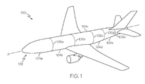
Fig. 1 is a perspective view of an aircraft assembled in accordance with the present disclosure; -
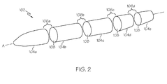
Fig. 2 is an exploded perspective view of a plurality of fuselage sections of the aircraft ofFig. 1 ; -
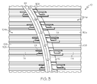
Fig. 3 is a partial perspective view of a splice joint between adjacent fuselage sections of the aircraft ofFig. 1 ; -
Fig. 4 is a partial perspective view of single splice of the splice joint ofFig. 3 ; -
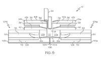
Fig. 5 is a partially exploded side perspective view of the splice ofFig. 4 ; -
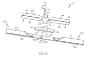
Fig. 6 is a partially exploded top perspective view of the splice ofFig. 4 ; -
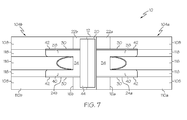
Fig. 7 is a top view of the splice ofFig. 4 ; -
Fig. 8 is a side view of the splice ofFig. 4 ; -
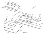
Fig. 9 is a partial exploded perspective view of the splice; and -
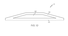
Fig. 10 is a cross section view of a splice plate of the disclosed splice. - The following detailed description refers to the accompanying drawings, which illustrate specific embodiments of the disclosure. Other embodiments having different structures and operations do not depart from the scope of the present disclosure. Like reference numerals may refer to the same element or component in the different drawings.
- Referring to
Figs. 1 and2 , anaircraft 100 may include afuselage 102 having a plurality of fuselage sections 104 (identified individually asfuselage sections 104a-e). The fuselage sections 104 may be joined together by a plurality of corresponding splice joints 106 (identified individually assplice joints 106a-e). - Each fuselage section 104 may include a
composite skin 108 extending three hundred sixty degrees (360°) around a longitudinal axis A of thefuselage 102. Throughout this disclosure, the term "fuselage section" is used for convenience to refer to any shell structure extending three hundred sixty degrees (360°) around an axis. It can be appreciated by one skilled in the art that a fuselage section 104 may not be limited to generally cylindrical structures, but may include structures having circular, elliptical, oval, egg-shaped, rectilinear, tapered, or other cross-sectional shapes. In addition, one skilled in the art can appreciate that the fuselage sections 104 may be one-piece sections in which theskins 108 are one-piece skins extending continuously for three hundred sixty degrees (360°) around the axis or can be formed from two or more skin segments joined together to form the full three hundred sixty degree (360°) fuselage section 104. - The
fuselage 102 may further include a passenger cabin configured to hold a plurality of passenger seats. Each fuselage section 104 may also include a plurality of window cutouts (not shown) to provide the passengers seated in the passenger cabin with views out of theaircraft 100. Thefuselage 102 may also include passenger doors, cargo doors, antennae and the like. - Referring to
Fig. 3 , a splice, generally designated 10, may bridge between and structurally join a pair of adjacently positioned fuselage sections 104 defining thesplice joint 106 therebetween. This view is looking outwardly at a portion of asplice joint 106 from within thefuselage 102. Thesplices 10 may be generally located at opposed ends of the fuselage sections 104. Thesplice 10 may be positioned interior of the fuselage sections 104 to integrate the fuselage sections 104 and provide strength and stability to the resultingfuselage 102. Although only a portion of the circumferentially extendingsplice 10 is illustrated inFIG. 3 , the splice may extend about the entire inner circumference of the fuselage sections 104 or may extend about only one or more portions thereof. - Each fuselage section 104 may include a panel 110 (identified individually as a
first panel 110a and asecond panel 110b). Afirst fuselage section 104a may include afirst panel 110a and asecond fuselage section 104b may include asecond panel 110b positioned in edgewise alignment with thefirst panel 110a. In one embodiment, the panels 110 may be at least generally similar in structure and function to known panel portions of aircraft fuselage sections. For example, the panel 110 may include a plurality of stiffeners orstringers 114 attached to theskin 108. Theskin 108 may be attached to and covers the plurality ofstringers 114 to form the exterior surface of the fuselage section 104. - Referring to
Figs. 4-8 , eachstringer 114 may include a raisedportion 116 projecting away from theskin 108 and a plurality offlange portions 118 attached directly to theskin 108. In the illustrated embodiment, thestringers 114 may have generally "U"-shaped cross-sections. However, it can be appreciated by one skilled in the art that thestringers 114 may have other cross-sectional shapes, including "L" shapes, "C" shapes, inverted "T" shapes, "I" shapes, etc. In yet other embodiments, the panels 110 may include other features; such as support members or offsets mated to theflange portions 118 of thestringers 114. - The
stringers 114 may be positioned on theskin 108 so that theflange portion 118 of onestringer 114 is aligned with acorresponding flange portion 118 of anadjacent stringer 114. By aligning theflange portions 118 in such a manner, theflange portions 118 may form a plurality of at least approximately continuous support surfaces extending between the raisedportions 116 of thestringers 114. In another embodiment, as illustrated, thestringers 114 may be spaced apart on theskin 108 so that theflange portion 118 of onestringer 114 is circumferentially offset (or otherwise spaced apart) from acorresponding flange portion 118 of anadjacent stringer 114. - Referring next to
Figs. 4-8 , which depict a segment of the splice joint 106 to more clearly illustrate the disclosedsplice 10. Thesplice 10 may include astrap 12 that extends at least partially circumferentially about thesplice joint 106 of the fuselage sections 104. Thestrap 12 may have a width, as defined in the longitudinal direction of thefuselage 102, which is sufficient to bridge across and overlie portions of both of the adjacent fuselage sections 104. - The
strap 12 may include abottom surface 14 to contact theskin 108 of the adjacent panels 110. Thebottom surface 14 may be curved and the curvature of the bottom surface may correspond to the curvature of the fuselage 102 (Fig. 2 ). Aflat bottom surface 14 is also contemplated. - Opposing sides 16 (identified individually in
Figs. 4 and5 asfirst side 16a andsecond side 16b) of thestrap 12 may extend away from the splice joint 106 and may be attached to an edge 120 (identified individually inFigs. 4 and5 asfirst edge 120a andsecond edge 120b) of theskin 108. Atop surface 18 of thesplice strap 12 may include a generally flatmiddle region 20 and opposing downwardly tapered regions 22 (identified individually inFigs. 4-6 as firsttapered region 22a and secondtapered region 22b) extending from proximate (i.e., at or near) themiddle region 20 to proximate the sides 16. As illustrated, in one embodiment, thesplice strap 12 may have a generally isosceles trapezoid cross sectional shape; however, it can be appreciated by one skilled in the art that thestrap 12 may have other generally trapezoidal shapes or other polygonal shapes. - As will be described in more detail herein, in one embodiment, the
strap 12 may be formed of a composite material, such as a carbon-fiber-reinforced polymer (CFRP), a composite fiber reinforced polymer, a graphite-epoxy, or similar material, so as to provide the strength and stability required to structurally join the adjacent fuselage sections 104 while reducing the material costs, weight, and drilling and assembly time relative to more conventional splices that utilize metal splice parts. In other embodiments, thestrap 12 may include other materials, including metallic materials such as aluminum, titanium, steel, etc. - The
strap 12 may be attached proximate thefirst edge 120a of theskin 108 of thefirst panel 110a and proximate thesecond edge 120b of theskin 108 of thesecond panel 110b to splice the panels 110 together. Thestrap 12 may extend continuously, or at least approximately continuously, around the splice joint 106. Alternatively, thestrap 12 may be segmented around the splice joint 106; for example, the splice joint 106 may include a plurality of segments of thestrap 12. Thestrap 12 may be attached to an inner side of therespective skins 108 to maintain a smooth, aerodynamic surface on the exterior of thefuselage 102. Thestrap 12 may be attached to theskins 108 by a plurality of fasteners extending through thestrap 12 and theskins 108. Alternatively, thestrap 12 may be bonded to theskins 108 or bonded and fastened to theskins 108. - The
strap 12 may be at least approximately as thick as theskins 108, but thicker thanadjacent flange portions 118 of thestringers 114. In one embodiment, as illustrated,stringers 114 do not extend completely to the edge 120 theskin 108 and the sides 16 of thestrap 12 may extend proximate the terminal end of thestringers 114. In other embodiments, thestringers 114 may extend to and terminate at the edge 120 of theskin 108. If needed to avoid a step between adjacent surfaces, shim pads or fillers (not shown) may be positioned on theflange portions 118 adjacent to thestrap 12. The fillers may include composite materials, metallic materials, or similar materials. In other embodiments, thestrap 12, theskins 108, and theflange portions 118 may have other relative thicknesses such that fillers may not be needed. - The
splice 10 may also include a plurality of splice fittings 24 (identified individually as a first fitting 24a and a second fitting 24b) that are disposed upon thestrap 12 and that extend in a longitudinal direction away from the splice joint 106. Each fitting 24 may include afirst end 26, asecond end 28, andlongitudinal sides 30. Abase 32 of the fitting 24 may include an upwardly taperedsection 34 extending proximate thefirst end 26 and a generallyflat section 36 extending proximate the taperedsection 34 to proximate thesecond end 28. Thefittings 24 may be formed of a composite material, such as carbon fiber reinforced plastic or similar material, such as the same composite that forms thestrap 12. Alternatively, thefittings 24 may be formed from a metal or metal alloy. - In the illustrated embodiment, the upwardly tapered
section 34 of the fitting 24 may include a correspondingly complimentary (i.e., opposing) upward angle relative the angle of the downwardly tapered region 22 of thestrap 12, such that the taperedsection 34 of thebottom surface 32 may make flush contact with the tapered region 22 of the straptop surface 18. The taperedsection 34 may have a width, as defined in the longitudinal direction of thefuselage 102, which is sufficient to extend across and overlie the tapered region 22 thestrap 12. Theflat section 36 of the fitting 24 may extend beyond the side 16 of thestrap 12 so as to overlie theskin 108 of the panel 110. A fitting 24 may be attached to the both tapered regions 22 of thestrap 12, such that a pair offittings 24 extends longitudinally beyond the opposed sides 16 of thestrap 12 away from the splice joint 106 so as to overlie the adjacent fuselage sections 104. - As shown in the illustrated embodiment, each fitting 24 may include a first
longitudinal member 38 and a secondlongitudinal member 40 that extend beyond the sides 16 of thestrap 12. Generally thelongitudinal members flat section 36 of the fitting 24. Thelongitudinally extending members stringer 114 of a respective panel 110. - For example, in one embodiment, each fitting 24 may be generally "U"-shaped such that each
longitudinal member respective stringer 114. Thefittings 24 of this embodiment may include the taperedsection 34 that extends across the width of the tapered region 22 of thestrap 12 and thelongitudinal members section 34 beyond the side 16 of thestrap 12. However, the taperedsection 34 of the fitting 24 may have other widths relative to the tapered region 22 of thestrap 12 and as such, the tapered section 22 of the fitting 12 may not need to extend across the entire width of the tapered region 22 of thestrap 12. Alternatively, the taperedsection 34 of the fitting 24 may extend beyond the tapered region 22 of thestrap 12 in other embodiments. - In other embodiments, the
flat section 36 of the fitting 24 may include a single longitudinal member that extends beyond the side 16 of thestrap 12. In such an embodiment, theflat section 36 may be suitably sized, i.e. the distance betweenlongitudinal sides 30, to fit between the raisedportions 116 of adj acent stringers 114. - The
splice 10 may include a plurality offittings 24 overlying different circumferentially spaced portions of thestrap 12. The plurality offittings 24 may be spaced apart from one another in a circumferential direction such that a portion of thestrap 12 may not be covered by a fitting 24 and may be exposed or visible between neighboring, i.e., adjacent,fittings 24. As such, thestrap 12 may be visually inspected to confirm that thestrap 12 remains properly secured to theskin 108 of the fuselage sections 104. Alternatively, the plurality offittings 24 may be abutted against one another in a circumferential direction such that theentire strap 12 may be covered byfittings 24. - In the illustrated embodiment, each fitting 24 may have a channel or "U"-shaped cross section that includes the
base 32, formed of the taperedsection 34 and theflat section 36, and opposing upstanding edges 42 (identified individually as a firstupstanding edge 42a and a secondupstanding edge 42b). A firstupstanding edge 42a being positioned toward a first longitudinal side 30a and a secondupstanding edge 42b being positioned toward a second longitudinal side 30b. In other embodiments, thefittings 24 may have other cross-sectional shapes, including "C" shapes, "L" shapes, inverted "Pi" shapes, and flat shapes. - The upstanding edges 42 may add stiffness to the
fittings 24 and may be positioned proximate to the raisedportions 116 of thestringers 114 depending upon the dimensions of theflat section 36 of the fitting 24 and the spaced apart distance of thestringers 114. The upstanding edges 42 may increase the stability of the splice joint 106, especially under compression loads. - If a
segmented strap 12 is used, then thefittings 24 may also be used as splice plates for adjacent strap segments. An advantage of the disclosed splice joint 106 is that the ends of thestringers 114 are left open, which enables moisture caused by condensation and other sources to escape thestringers 114 for sufficient drainage. - Yet another advantage of the disclosed
splice 10 is that the raisedportions 116 of opposingstringers 114 are not spliced together across the splice joint 106, which may make thefittings 24 relatively easy to install because the raisedportions 116 do not have to be in perfect alignment. Additionally, the ability to shift or adjust the position of the fitting 24 along both sides 16 of thestrap 12 allows thelongitudinal members portion 116 of thestringer 114 if not perfectly aligned with an opposingstringer 114. - The
splice 10 may optionally include aframe 44 that extends circumferentially about at least a portion of the splice joint 106 between adjacent fuselage sections 104. Theframe 44 may be generally positioned to overlie themiddle region 20 of thestrap 12 between longitudinally opposedfittings 24. In the illustrated embodiment, theframe 44 may have a generally "Z" shape configured to have an upturnedlower flange 46 to be fastened to thestrap 12. Thelower flange 46 may be segmented into a plurality of feet, which may be fastened to thestrap 12, as illustrated inFig. 3 . Theframe 44 may also include a downturnedupper flange 48 to be fastened to an exterior of the inner cabin walls of thefuselage 102. Theupper flange 48 may be segmented into feet in a similar manner as described for thelower flange 46. While a Z-shapedframe 44 is shown, those skilled in the art will appreciate that any suitable frame may be used, such as a C-shaped frame, an I-shaped frame, a J-shaped frame or the like. - The
frame 44 may also be formed of a composite material, such as CFRP or similar material, such as the same composite that forms thestrap 12 or thefittings 24. Alternatively, theframe 44 may be formed of a metallic or other material, such as aluminum or titanium. - Although the disclosed
splice 10 is illustrated as being built up from a number of separate parts (e.g., thestrap 12, thefittings 24, the frame 44), in other embodiments, two or more of these parts may be integrated into a single part that performs the function or has the features of the two or more parts. - Referring next to
Fig. 9 , a benefit of the disclosedsplice 10 is the contemplated elimination of the need for metal components, such as titanium metal components, in the splice joint 106 and the significant reduction (if not complete elimination) of the need for shims or non-conformance tags during assembly of thefuselage 102. Another benefit of the disclosedsplice 10 is the significant reduction in manufacturing flow times offuselage 102 assembly contemplated by installing, i.e., fastening, thesplice strap 12 and a portion of the plurality ofsplice fittings 24a to thefirst fuselage section 104a prior to integration of the adjacentsecond fuselage section 104b and corresponding portion of the plurality of longitudinally opposedsplice fittings 24b. Optionally, theframe 44 may also be installed prior to integration of thesecond fuselage section 104b. - As best illustrated in
Figs. 4 ,6 , and8 , the interface between the tapered region 22 of thestrap 12 and thetapered sections 34 of thefittings 24 allow for thefittings 24 to be fastened to thestrap 12 and the panel 110 without the requirement of shimming and allows for location allowances between the adjacent fuselage sections 104 andfittings 24. For example, during installation of thefittings 24, each fitting 24 may be shifted longitudinally forward or rearward, i.e., fore and aft, relative to thestrap 12 to account for varying thicknesses and termination locations offlange portions 118 of thestringers 114 to provide for a shimless splice joint 106. The opposing tapered surfaces of thestrap 12 and thefittings 24 may also minimize centroid shifting throughout the splice joint 106, which may reduce out of plane loads along the splice joint 106. Additionally, the tapered interface may also lessen load transfer at the fasteners and more evenly transfer load forces between the splice members, i.e., thestrap 12, thefittings 24, and butt joined fuselage sections 104. - Referring to
Fig. 10 , thesplice strap 12 may be formed through composite ply dropping to internally achieve the tapered regions 22 without the requirement of post formation machining. Thesplice fittings 24 may also be formed through composite ply dropping to internally achieve the taperedsection 34 without the requirement of post formation machining. Thestrap 12 and thefittings 24 may include an internaltapered structure 50 surrounded by a plurality of fiber layers and a cured resin, i.e.,composite ply 52, to form a composite structure. For example, thestrap 12 may include an exterior continuous fiber zone and an internal tapered fiber zone. A plurality of plies may laid up to form a lower continuous fiber zone. Another plurality of plies may be laid up within a perimeter border of the lower continuous fiber zone to form the tapered fiber zone or taperedstructure 50. Alternatively, the taperedstructure 50 may be formed from alternate materials. Another plurality of plies may be laid up over the tapered fiber zone to form an upper continuous fiber zone. Theplies 52 may be pre-impregnated composite layers. Thesplice fittings 24 may be formed through a substantially similar process to form the taperedsection 34 of thebase 32. - One advantage of using composite materials instead of metals is that the
strap 12,fittings 24, and the underlying panels 110 (e.g., theskins 108 and stringers 114) may have at least generally similar coefficients of thermal expansion. As a result, temperature fluctuations experienced during operation of theaircraft 100 may not cause disparate thermal expansion between thesplice 10 and the underlying panels 110, which may not induce significant stresses in the splice joint 106. Another advantage of using composite materials is the elimination of the need for dissimilar material isolation. - It can be appreciated by one skilled in the art that in addition to composites and metal materials, in yet other embodiments, the panels 110, the
strap 12, and thefittings 24, and combinations thereof, may include other materials, including hybrid materials such as fiber/metal laminates, including fiberglass/aluminum laminates and titanium reinforced graphite laminates (Ti/Gr). - The
splice 10 may includes a plurality of fasteners that join the components of thesplice 10 to one another and to the fuselage sections 104. Various fastener patterns for which the fasteners may be installed in order to connect thesplice 10 to thefuselage sections 102 may be utilized and have not been illustrated. The fasteners may extend through thestrap 12; the frame, such as about thelower flange 46; and thefittings 24, such as both the taperedsection 34 and thelongitudinally extending members flat section 36 so as to connect the components to one another and to the fuselage sections 104. - In order to install the plurality of fasteners, a plurality of holes must be formed, such as by drilling, in the various components of the
splice 10 so as to receive respective fasteners. Since a number of the holes, and in certain embodiments a majority of the holes, may be formed through components, e.g., thestrap 12, thefittings 24, and optionally theframe 44, that are formed of a composite material, such as CFRP, the holes may be formed more rapidly and efficiently than the formation of comparable holes through titanium or other metal components. Additionally, the holes that are formed through the composite components of a splice10 may be formed even more efficiently and cost effectively than comparable holes formed through comparable metal or titanium components since the components of thesplice 10 need not be separated and deburred. - Another advantage of the disclosed
splice 10 is that the components may be fastened with titanium fasteners, as opposed to Inconel® or other steel fasteners, since composite components may not be as sensitive to fatigue load in the same manner as comparable metal parts. As such, the composite components generally do not require the high level of clamp-up forces required by metal parts that utilize Inconel® or other steel fasteners. - Although various embodiments of the disclosed splice joint have been shown and described, modifications may occur to those skilled in the art upon reading the specification. The present application includes such modifications and is limited only by the scope of the claims.
- According to an aspect of the present disclosure there is provided a splice for joining adjacent panels of a shell structure comprising: a strap comprising a first side, a second side, a generally flat middle region, a first tapered region extending downwardly proximate said middle region to proximate said first side, and a second tapered region extending downwardly proximate said middle region to proximate said second side; a first fitting comprising a tapered section and a flat section, said tapered section attached to said first tapered region of said strap; and, a second fitting comprising a tapered section and a flat section, said tapered section attached to said second tapered region of said strap. Advantageously the splice further comprises a frame attached to said middle region of said strap. Advantageously the splice comprises a composite material. Advantageously, the strap further comprises a tapered internal structure surrounded by a carbon fiber reinforced plastic.
Claims (15)
- A shell structure splice comprising:a first panel comprising a first edge;a strap attached to said first panel and extending beyond said first edge, said strap comprising a first tapered region; and,a first fitting comprising a tapered section and a flat section, said tapered section attached to said first tapered region of said strap.
- The splice of Claim 1 wherein at least a portion of said first tapered region of said strap is positioned between said first fitting and said first panel.
- The splice of any preceding claim further comprising:a second panel comprising a second edge, said second edge being positioned in edgewise alignment with said first edge to form a splice joint;said strap bridges said splice joint and is fastened to said second panel, said strap further comprising a second tapered region; and,a second fitting comprising a tapered section and a flat section, said tapered section attached to said second tapered region of said strap.
- The splice of Claim 3 wherein said first panel and said second panel are fuselage sections of an aircraft.
- The splice of Claims 3 or 4 wherein said strap comprises a top surface, a bottom surface, a first side, and a second side, said top surface comprising a generally flat middle region;
wherein said first tapered region extends downwardly proximate said middle region to proximate said first side; and,
wherein said second tapered region extends downwardly proximate said middle region to proximate said second side. - The splice of Claim 5 wherein said flat section of said first fitting extends beyond said first side of said strap and is attached to said first panel and said flat section of said second fitting extends beyond said second side of said strap and is attached to said second panel.
- The splice of Claim 6 wherein said flat section of said first fitting and said second fitting each comprises a first longitudinal member and a spaced apart second longitudinal member.
- The splice of any preceding claim wherein said strap comprises a composite material.
- The splice of any preceding claim wherein said strap further comprises a tapered internal structure surrounded by a carbon fiber reinforced plastic.
- The splice of claims 5-9 further comprising a frame attached to said middle region of said strap.
- A method of joining a shell structure, said method comprising the steps of:providing a first panel of said shell structure comprising a first edge;providing a strap comprising a first tapered region and a second tapered region;positioning said strap adjacent to said first edge such that said first tapered region is adjacent to said first panel and said second tapered region extends outwardly from said first edge;attaching said strap to said first panel;providing a first fitting comprising a tapered section and a flat section;positioning said first fitting such that said tapered section is adjacent said first tapered region of said strap and said flat section is adjacent said first panel;attaching said first fitting to said strap; andattaching said first fitting to said first panel.
- The method of Claim 11 further comprising the steps of:providing a second panel of said shell structure comprising a second edge;positioning said second panel adjacent said first panel such that said first and second edges are in edgewise alignment forming a splice joint and said second tapered section is adjacent said second panel and said strap bridges said splice joint;attaching said strap to said second panel;providing a second fitting comprising a tapered section and a flat section;positioning said second fitting such that said tapered section is adjacent said second tapered region of said strap and said flat section is adjacent said second panel;attaching said second fitting to said strap; andattaching said second fitting to said second panel.
- The method of Claims 11 or 12 further comprising the steps of:providing a frame;positioning said frame adjacent to said strap between said first tapered region and said second tapered region; andattaching said frame to said strap.
- The method of Claim 13 wherein said first panel and said second panel are fuselage sections of an aircraft.
- The method of Claim 13 or 14 wherein at least one of said strap, said first fitting, said second fitting, and said frame comprise a composite material.
Applications Claiming Priority (1)
| Application Number | Priority Date | Filing Date | Title |
|---|---|---|---|
| US13/665,664 US8960606B2 (en) | 2012-10-31 | 2012-10-31 | Circumference splice for joining shell structures |
Publications (2)
| Publication Number | Publication Date |
|---|---|
| EP2727821A1 true EP2727821A1 (en) | 2014-05-07 |
| EP2727821B1 EP2727821B1 (en) | 2017-03-29 |
Family
ID=49509930
Family Applications (1)
| Application Number | Title | Priority Date | Filing Date |
|---|---|---|---|
| EP13189955.1A Active EP2727821B1 (en) | 2012-10-31 | 2013-10-23 | Circumference splice for joining shell structures |
Country Status (10)
| Country | Link |
|---|---|
| US (1) | US8960606B2 (en) |
| EP (1) | EP2727821B1 (en) |
| JP (1) | JP6342641B2 (en) |
| KR (1) | KR101858274B1 (en) |
| CN (1) | CN103786868B (en) |
| AU (1) | AU2013228054B2 (en) |
| BR (1) | BR102013027906B1 (en) |
| CA (1) | CA2828723C (en) |
| ES (1) | ES2622301T3 (en) |
| RU (1) | RU2658211C2 (en) |
Cited By (8)
| Publication number | Priority date | Publication date | Assignee | Title |
|---|---|---|---|---|
| EP3028940A1 (en) * | 2014-12-02 | 2016-06-08 | The Boeing Company | Splice assembly for joining structural components |
| EP3293105A1 (en) * | 2016-09-07 | 2018-03-14 | The Boeing Company | Method of repairing damage to fuselage barrel and associated apparatus and system |
| EP3354384A1 (en) * | 2017-01-25 | 2018-08-01 | The Boeing Company | Method and system for joining structures |
| EP3533705A1 (en) * | 2018-03-02 | 2019-09-04 | The Boeing Company | Stringer transition through a common base charge |
| EP3702286A1 (en) * | 2019-02-26 | 2020-09-02 | The Boeing Company | Bulkhead shims for curvilinear components |
| FR3101611A1 (en) * | 2019-10-02 | 2021-04-09 | Airbus Operations (S.A.S.) | Reinforced panel with a honeycomb structure comprising at least one connection zone having an extra thickness and aircraft comprising at least one such reinforced panel |
| EP4282754A1 (en) | 2022-05-24 | 2023-11-29 | AIRBUS HELICOPTERS DEUTSCHLAND GmbH | An attachment assembly for attachment of a tail boom to a rear fuselage of a rotorcraft |
| US11873072B2 (en) | 2021-01-20 | 2024-01-16 | The Boeing Company | Pressure bulkhead assembly methods and systems |
Families Citing this family (28)
| Publication number | Priority date | Publication date | Assignee | Title |
|---|---|---|---|---|
| US7325771B2 (en) * | 2004-09-23 | 2008-02-05 | The Boeing Company | Splice joints for composite aircraft fuselages and other structures |
| DE102011004844A1 (en) * | 2011-02-28 | 2012-08-30 | Airbus Operations Gmbh | Door frame composite, fuselage section and aircraft or spacecraft |
| US8960604B1 (en) * | 2011-09-07 | 2015-02-24 | The Boeing Company | Composite fuselage system with composite fuselage sections |
| EP2759467B1 (en) * | 2013-01-24 | 2016-10-19 | Airbus Operations GmbH | Aircraft frame and method of mounting two fuselage segments |
| ES2819076T3 (en) * | 2013-04-30 | 2021-04-14 | Airbus Operations Sl | Composite structure for an aircraft and its manufacturing process |
| US10189578B2 (en) * | 2013-06-12 | 2019-01-29 | The Boeing Company | Self-balancing pressure bulkhead |
| WO2015094059A1 (en) * | 2013-12-20 | 2015-06-25 | Saab Ab | Stiffening element and reinforced structure |
| GB2528080A (en) * | 2014-07-08 | 2016-01-13 | Airbus Operations Ltd | Structure |
| US9593740B2 (en) * | 2015-05-13 | 2017-03-14 | The Boeing Company | Energy-absorbing composite tension-shear fitting |
| US10099445B2 (en) | 2015-05-14 | 2018-10-16 | The Boeing Company | Systems and methods for forming composite materials |
| US10450870B2 (en) | 2016-02-09 | 2019-10-22 | General Electric Company | Frangible gas turbine engine airfoil |
| JP7050458B2 (en) * | 2017-02-14 | 2022-04-08 | ザ・ボーイング・カンパニー | How to assemble a composite core sandwich edge joint |
| RU2019134627A (en) * | 2017-03-30 | 2021-04-30 | Си Энд Ди ЗОДИАК, ИНК. | SIDE PANEL ASSEMBLY |
| US11572148B2 (en) * | 2018-06-04 | 2023-02-07 | The Boeing Company | Aircraft stringers having CFRP material reinforced flanges |
| US11180238B2 (en) * | 2018-11-19 | 2021-11-23 | The Boeing Company | Shear ties for aircraft wing |
| US11198497B2 (en) * | 2019-06-19 | 2021-12-14 | The Boeing Company | Splice fittings that are affixed to stringers via web-installed fasteners |
| US10864999B1 (en) | 2019-07-18 | 2020-12-15 | QMI, Inc. | Cessna tail-cone reinforcement angle splice, installation kit, and method for installation thereof |
| CN110466734B (en) * | 2019-08-26 | 2022-08-19 | 中国航空工业集团公司沈阳飞机设计研究所 | Band plate of sawtooth seam butt joint skin |
| CN111100589A (en) * | 2020-01-20 | 2020-05-05 | 厦门天源欧瑞科技有限公司 | Glue, preparation method thereof and preparation method of unmanned aerial vehicle shell |
| US11459124B2 (en) | 2020-02-21 | 2022-10-04 | The Boeing Company | Assembly tool for fuselage structure splice |
| US11524762B2 (en) * | 2020-02-21 | 2022-12-13 | The Boeing Company | Fuselage structure splice |
| FR3114574A1 (en) * | 2020-09-30 | 2022-04-01 | Airbus Operations | Interface element for connecting two aircraft fuselage sections with a reduced number of parts. |
| US11919617B2 (en) * | 2020-12-17 | 2024-03-05 | The Boeing Company | Circumferential lap splices for sections of fuselage |
| US11845528B2 (en) | 2021-01-20 | 2023-12-19 | The Boeing Company | Pressure bulkhead assembly and method and system for making the same |
| GB2615755A (en) * | 2022-02-15 | 2023-08-23 | Airbus Operations Ltd | Fuel tank stringer with flow passage |
| US20240425201A1 (en) * | 2023-06-21 | 2024-12-26 | The Boeing Company | Systems and methods for shimless assembly and joint splices |
| US20250382047A1 (en) * | 2024-06-14 | 2025-12-18 | The Boeing Company | Composite panels with titanium ends |
| EP4703258A1 (en) * | 2024-08-28 | 2026-03-04 | Airbus Operations, S.L.U. | Fitting structure for aircraft fuselage |
Citations (4)
| Publication number | Priority date | Publication date | Assignee | Title |
|---|---|---|---|---|
| US4606961A (en) * | 1984-10-09 | 1986-08-19 | The Boeing Company | Discretely stiffened composite panel |
| EP1566334A1 (en) * | 2004-02-20 | 2005-08-24 | Airbus France | Stiffener end with staggered slopes and panel with such stiffener end |
| WO2011001050A1 (en) * | 2009-07-03 | 2011-01-06 | Airbus Operations | Fuselage element comprising a fuselage segment and junction means |
| US20120153082A1 (en) * | 2010-12-15 | 2012-06-21 | The Boeing Company | Splice and associated method for joining fuselage sections |
Family Cites Families (7)
| Publication number | Priority date | Publication date | Assignee | Title |
|---|---|---|---|---|
| US7325771B2 (en) | 2004-09-23 | 2008-02-05 | The Boeing Company | Splice joints for composite aircraft fuselages and other structures |
| US8398027B2 (en) * | 2007-09-17 | 2013-03-19 | The Boeing Company | Method and apparatus for reinforcing composite structures |
| FR2922518B1 (en) * | 2007-10-18 | 2010-04-23 | Airbus France | AIRCRAFT STRUCTURE COMPRISING STIFF STOP JUNCTIONS |
| FR2922517B1 (en) * | 2007-10-18 | 2010-04-23 | Airbus France | AIRCRAFT COMPRISING SUNNY ARRESTOR JUNCTIONS AND METHOD OF MANUFACTURING SUCH A PLANE |
| DE102007055233A1 (en) * | 2007-11-20 | 2009-05-28 | Airbus Deutschland Gmbh | Coupling device for joining fuselage sections, combination of a coupling device and at least one fuselage section and method for producing the coupling device |
| DE102008013365B4 (en) * | 2008-03-10 | 2011-03-17 | Airbus Operations Gmbh | Transverse joint between two fuselage sections |
| US8714488B2 (en) * | 2009-01-08 | 2014-05-06 | The Boeing Company | Elastic aircraft joint fairing |
-
2012
- 2012-10-31 US US13/665,664 patent/US8960606B2/en active Active
-
2013
- 2013-09-16 AU AU2013228054A patent/AU2013228054B2/en active Active
- 2013-10-01 CA CA2828723A patent/CA2828723C/en active Active
- 2013-10-08 KR KR1020130120086A patent/KR101858274B1/en active Active
- 2013-10-23 ES ES13189955.1T patent/ES2622301T3/en active Active
- 2013-10-23 EP EP13189955.1A patent/EP2727821B1/en active Active
- 2013-10-25 JP JP2013222203A patent/JP6342641B2/en active Active
- 2013-10-29 CN CN201310519891.7A patent/CN103786868B/en active Active
- 2013-10-30 BR BR102013027906-4A patent/BR102013027906B1/en active IP Right Grant
- 2013-10-30 RU RU2013148371A patent/RU2658211C2/en active
Patent Citations (4)
| Publication number | Priority date | Publication date | Assignee | Title |
|---|---|---|---|---|
| US4606961A (en) * | 1984-10-09 | 1986-08-19 | The Boeing Company | Discretely stiffened composite panel |
| EP1566334A1 (en) * | 2004-02-20 | 2005-08-24 | Airbus France | Stiffener end with staggered slopes and panel with such stiffener end |
| WO2011001050A1 (en) * | 2009-07-03 | 2011-01-06 | Airbus Operations | Fuselage element comprising a fuselage segment and junction means |
| US20120153082A1 (en) * | 2010-12-15 | 2012-06-21 | The Boeing Company | Splice and associated method for joining fuselage sections |
Cited By (17)
| Publication number | Priority date | Publication date | Assignee | Title |
|---|---|---|---|---|
| EP3388330A1 (en) * | 2014-12-02 | 2018-10-17 | The Boeing Company | Splice assembly for joining structural components |
| US9586667B2 (en) | 2014-12-02 | 2017-03-07 | The Boeing Company | Splice assembly for joining structural components |
| EP3028940A1 (en) * | 2014-12-02 | 2016-06-08 | The Boeing Company | Splice assembly for joining structural components |
| EP3659905A1 (en) * | 2014-12-02 | 2020-06-03 | The Boeing Company | Splice assembly for joining structural components |
| US11104412B2 (en) | 2016-09-07 | 2021-08-31 | The Boeing Company | Method of repairing damage to fuselage barrel and associated apparatus and system |
| US10308342B2 (en) | 2016-09-07 | 2019-06-04 | The Boeing Company | Method of repairing damage to fuselage barrel and associated apparatus and system |
| EP3293105A1 (en) * | 2016-09-07 | 2018-03-14 | The Boeing Company | Method of repairing damage to fuselage barrel and associated apparatus and system |
| EP3354384A1 (en) * | 2017-01-25 | 2018-08-01 | The Boeing Company | Method and system for joining structures |
| US10934020B2 (en) | 2017-01-25 | 2021-03-02 | The Boeing Company | Method and system for joining structures |
| US11370563B2 (en) | 2017-01-25 | 2022-06-28 | The Boeing Company | Method and system for joining structures |
| EP3533705A1 (en) * | 2018-03-02 | 2019-09-04 | The Boeing Company | Stringer transition through a common base charge |
| US10745104B2 (en) | 2018-03-02 | 2020-08-18 | The Boeing Company | Stringer transition through a common base charge |
| EP3702286A1 (en) * | 2019-02-26 | 2020-09-02 | The Boeing Company | Bulkhead shims for curvilinear components |
| US11280222B2 (en) | 2019-02-26 | 2022-03-22 | The Boeing Company | Bulkhead shims for curvilinear components |
| FR3101611A1 (en) * | 2019-10-02 | 2021-04-09 | Airbus Operations (S.A.S.) | Reinforced panel with a honeycomb structure comprising at least one connection zone having an extra thickness and aircraft comprising at least one such reinforced panel |
| US11873072B2 (en) | 2021-01-20 | 2024-01-16 | The Boeing Company | Pressure bulkhead assembly methods and systems |
| EP4282754A1 (en) | 2022-05-24 | 2023-11-29 | AIRBUS HELICOPTERS DEUTSCHLAND GmbH | An attachment assembly for attachment of a tail boom to a rear fuselage of a rotorcraft |
Also Published As
| Publication number | Publication date |
|---|---|
| CA2828723A1 (en) | 2014-04-30 |
| EP2727821B1 (en) | 2017-03-29 |
| BR102013027906A2 (en) | 2014-10-21 |
| BR102013027906B1 (en) | 2022-01-11 |
| CA2828723C (en) | 2016-11-22 |
| KR20140055989A (en) | 2014-05-09 |
| KR101858274B1 (en) | 2018-05-15 |
| RU2013148371A (en) | 2015-05-10 |
| RU2658211C2 (en) | 2018-06-19 |
| AU2013228054B2 (en) | 2016-12-22 |
| JP2014111433A (en) | 2014-06-19 |
| AU2013228054A1 (en) | 2014-05-15 |
| CN103786868A (en) | 2014-05-14 |
| US8960606B2 (en) | 2015-02-24 |
| CN103786868B (en) | 2017-09-12 |
| ES2622301T3 (en) | 2017-07-06 |
| US20140117157A1 (en) | 2014-05-01 |
| JP6342641B2 (en) | 2018-06-13 |
Similar Documents
| Publication | Publication Date | Title |
|---|---|---|
| EP2727821B1 (en) | Circumference splice for joining shell structures | |
| US8567722B2 (en) | Splice and associated method for joining fuselage sections | |
| CN101883717B (en) | System of aircraft fuselage two sections and connection structure for fuselage skin connection | |
| EP2164754B1 (en) | Method for coupling stiffening profile elements and structural component | |
| RU2529081C2 (en) | Joint assembly | |
| US8186622B2 (en) | Aircraft component | |
| US8418963B2 (en) | Aircraft load frame made of a composite material | |
| CN101959753B (en) | Transverse joint connection between two fuselage sections | |
| US20160251071A1 (en) | Splice joints for composite aircraft fuselages and other structures | |
| US20100083504A1 (en) | Methods of manufacturing structural panels | |
| EP2621802B1 (en) | Stiffener run-out | |
| US20110185555A1 (en) | Method for the orbital assembly of aircraft sections made of composite material | |
| US20160325820A1 (en) | Structural component | |
| US7677496B2 (en) | Stringer for an aircraft wing and a method of reinforcing thereof | |
| CN113291454B (en) | Fuselage structure splicing parts |
Legal Events
| Date | Code | Title | Description |
|---|---|---|---|
| PUAI | Public reference made under article 153(3) epc to a published international application that has entered the european phase |
Free format text: ORIGINAL CODE: 0009012 |
|
| 17P | Request for examination filed |
Effective date: 20131023 |
|
| AK | Designated contracting states |
Kind code of ref document: A1 Designated state(s): AL AT BE BG CH CY CZ DE DK EE ES FI FR GB GR HR HU IE IS IT LI LT LU LV MC MK MT NL NO PL PT RO RS SE SI SK SM TR |
|
| AX | Request for extension of the european patent |
Extension state: BA ME |
|
| GRAP | Despatch of communication of intention to grant a patent |
Free format text: ORIGINAL CODE: EPIDOSNIGR1 |
|
| INTG | Intention to grant announced |
Effective date: 20161020 |
|
| GRAS | Grant fee paid |
Free format text: ORIGINAL CODE: EPIDOSNIGR3 |
|
| GRAA | (expected) grant |
Free format text: ORIGINAL CODE: 0009210 |
|
| AK | Designated contracting states |
Kind code of ref document: B1 Designated state(s): AL AT BE BG CH CY CZ DE DK EE ES FI FR GB GR HR HU IE IS IT LI LT LU LV MC MK MT NL NO PL PT RO RS SE SI SK SM TR |
|
| REG | Reference to a national code |
Ref country code: GB Ref legal event code: FG4D |
|
| REG | Reference to a national code |
Ref country code: CH Ref legal event code: EP |
|
| REG | Reference to a national code |
Ref country code: AT Ref legal event code: REF Ref document number: 879481 Country of ref document: AT Kind code of ref document: T Effective date: 20170415 |
|
| REG | Reference to a national code |
Ref country code: IE Ref legal event code: FG4D |
|
| REG | Reference to a national code |
Ref country code: DE Ref legal event code: R096 Ref document number: 602013019120 Country of ref document: DE |
|
| REG | Reference to a national code |
Ref country code: ES Ref legal event code: FG2A Ref document number: 2622301 Country of ref document: ES Kind code of ref document: T3 Effective date: 20170706 |
|
| PG25 | Lapsed in a contracting state [announced via postgrant information from national office to epo] |
Ref country code: GR Free format text: LAPSE BECAUSE OF FAILURE TO SUBMIT A TRANSLATION OF THE DESCRIPTION OR TO PAY THE FEE WITHIN THE PRESCRIBED TIME-LIMIT Effective date: 20170630 Ref country code: FI Free format text: LAPSE BECAUSE OF FAILURE TO SUBMIT A TRANSLATION OF THE DESCRIPTION OR TO PAY THE FEE WITHIN THE PRESCRIBED TIME-LIMIT Effective date: 20170329 Ref country code: NO Free format text: LAPSE BECAUSE OF FAILURE TO SUBMIT A TRANSLATION OF THE DESCRIPTION OR TO PAY THE FEE WITHIN THE PRESCRIBED TIME-LIMIT Effective date: 20170629 Ref country code: LT Free format text: LAPSE BECAUSE OF FAILURE TO SUBMIT A TRANSLATION OF THE DESCRIPTION OR TO PAY THE FEE WITHIN THE PRESCRIBED TIME-LIMIT Effective date: 20170329 Ref country code: HR Free format text: LAPSE BECAUSE OF FAILURE TO SUBMIT A TRANSLATION OF THE DESCRIPTION OR TO PAY THE FEE WITHIN THE PRESCRIBED TIME-LIMIT Effective date: 20170329 |
|
| REG | Reference to a national code |
Ref country code: NL Ref legal event code: MP Effective date: 20170329 |
|
| REG | Reference to a national code |
Ref country code: AT Ref legal event code: MK05 Ref document number: 879481 Country of ref document: AT Kind code of ref document: T Effective date: 20170329 |
|
| PG25 | Lapsed in a contracting state [announced via postgrant information from national office to epo] |
Ref country code: LV Free format text: LAPSE BECAUSE OF FAILURE TO SUBMIT A TRANSLATION OF THE DESCRIPTION OR TO PAY THE FEE WITHIN THE PRESCRIBED TIME-LIMIT Effective date: 20170329 Ref country code: SE Free format text: LAPSE BECAUSE OF FAILURE TO SUBMIT A TRANSLATION OF THE DESCRIPTION OR TO PAY THE FEE WITHIN THE PRESCRIBED TIME-LIMIT Effective date: 20170329 Ref country code: RS Free format text: LAPSE BECAUSE OF FAILURE TO SUBMIT A TRANSLATION OF THE DESCRIPTION OR TO PAY THE FEE WITHIN THE PRESCRIBED TIME-LIMIT Effective date: 20170329 Ref country code: BG Free format text: LAPSE BECAUSE OF FAILURE TO SUBMIT A TRANSLATION OF THE DESCRIPTION OR TO PAY THE FEE WITHIN THE PRESCRIBED TIME-LIMIT Effective date: 20170629 |
|
| PG25 | Lapsed in a contracting state [announced via postgrant information from national office to epo] |
Ref country code: NL Free format text: LAPSE BECAUSE OF FAILURE TO SUBMIT A TRANSLATION OF THE DESCRIPTION OR TO PAY THE FEE WITHIN THE PRESCRIBED TIME-LIMIT Effective date: 20170329 |
|
| REG | Reference to a national code |
Ref country code: FR Ref legal event code: PLFP Year of fee payment: 5 |
|
| PG25 | Lapsed in a contracting state [announced via postgrant information from national office to epo] |
Ref country code: AT Free format text: LAPSE BECAUSE OF FAILURE TO SUBMIT A TRANSLATION OF THE DESCRIPTION OR TO PAY THE FEE WITHIN THE PRESCRIBED TIME-LIMIT Effective date: 20170329 Ref country code: SK Free format text: LAPSE BECAUSE OF FAILURE TO SUBMIT A TRANSLATION OF THE DESCRIPTION OR TO PAY THE FEE WITHIN THE PRESCRIBED TIME-LIMIT Effective date: 20170329 Ref country code: EE Free format text: LAPSE BECAUSE OF FAILURE TO SUBMIT A TRANSLATION OF THE DESCRIPTION OR TO PAY THE FEE WITHIN THE PRESCRIBED TIME-LIMIT Effective date: 20170329 Ref country code: RO Free format text: LAPSE BECAUSE OF FAILURE TO SUBMIT A TRANSLATION OF THE DESCRIPTION OR TO PAY THE FEE WITHIN THE PRESCRIBED TIME-LIMIT Effective date: 20170329 Ref country code: CZ Free format text: LAPSE BECAUSE OF FAILURE TO SUBMIT A TRANSLATION OF THE DESCRIPTION OR TO PAY THE FEE WITHIN THE PRESCRIBED TIME-LIMIT Effective date: 20170329 |
|
| PG25 | Lapsed in a contracting state [announced via postgrant information from national office to epo] |
Ref country code: PL Free format text: LAPSE BECAUSE OF FAILURE TO SUBMIT A TRANSLATION OF THE DESCRIPTION OR TO PAY THE FEE WITHIN THE PRESCRIBED TIME-LIMIT Effective date: 20170329 Ref country code: IS Free format text: LAPSE BECAUSE OF FAILURE TO SUBMIT A TRANSLATION OF THE DESCRIPTION OR TO PAY THE FEE WITHIN THE PRESCRIBED TIME-LIMIT Effective date: 20170729 Ref country code: SM Free format text: LAPSE BECAUSE OF FAILURE TO SUBMIT A TRANSLATION OF THE DESCRIPTION OR TO PAY THE FEE WITHIN THE PRESCRIBED TIME-LIMIT Effective date: 20170329 Ref country code: PT Free format text: LAPSE BECAUSE OF FAILURE TO SUBMIT A TRANSLATION OF THE DESCRIPTION OR TO PAY THE FEE WITHIN THE PRESCRIBED TIME-LIMIT Effective date: 20170731 |
|
| REG | Reference to a national code |
Ref country code: DE Ref legal event code: R097 Ref document number: 602013019120 Country of ref document: DE |
|
| PG25 | Lapsed in a contracting state [announced via postgrant information from national office to epo] |
Ref country code: DK Free format text: LAPSE BECAUSE OF FAILURE TO SUBMIT A TRANSLATION OF THE DESCRIPTION OR TO PAY THE FEE WITHIN THE PRESCRIBED TIME-LIMIT Effective date: 20170329 |
|
| PLBE | No opposition filed within time limit |
Free format text: ORIGINAL CODE: 0009261 |
|
| STAA | Information on the status of an ep patent application or granted ep patent |
Free format text: STATUS: NO OPPOSITION FILED WITHIN TIME LIMIT |
|
| 26N | No opposition filed |
Effective date: 20180103 |
|
| PG25 | Lapsed in a contracting state [announced via postgrant information from national office to epo] |
Ref country code: SI Free format text: LAPSE BECAUSE OF FAILURE TO SUBMIT A TRANSLATION OF THE DESCRIPTION OR TO PAY THE FEE WITHIN THE PRESCRIBED TIME-LIMIT Effective date: 20170329 Ref country code: MC Free format text: LAPSE BECAUSE OF FAILURE TO SUBMIT A TRANSLATION OF THE DESCRIPTION OR TO PAY THE FEE WITHIN THE PRESCRIBED TIME-LIMIT Effective date: 20170329 |
|
| REG | Reference to a national code |
Ref country code: CH Ref legal event code: PL |
|
| REG | Reference to a national code |
Ref country code: IE Ref legal event code: MM4A |
|
| PG25 | Lapsed in a contracting state [announced via postgrant information from national office to epo] |
Ref country code: CH Free format text: LAPSE BECAUSE OF NON-PAYMENT OF DUE FEES Effective date: 20171031 Ref country code: LI Free format text: LAPSE BECAUSE OF NON-PAYMENT OF DUE FEES Effective date: 20171031 Ref country code: LU Free format text: LAPSE BECAUSE OF NON-PAYMENT OF DUE FEES Effective date: 20171023 |
|
| REG | Reference to a national code |
Ref country code: BE Ref legal event code: MM Effective date: 20171031 |
|
| PG25 | Lapsed in a contracting state [announced via postgrant information from national office to epo] |
Ref country code: BE Free format text: LAPSE BECAUSE OF NON-PAYMENT OF DUE FEES Effective date: 20171031 |
|
| PG25 | Lapsed in a contracting state [announced via postgrant information from national office to epo] |
Ref country code: MT Free format text: LAPSE BECAUSE OF NON-PAYMENT OF DUE FEES Effective date: 20171023 |
|
| REG | Reference to a national code |
Ref country code: FR Ref legal event code: PLFP Year of fee payment: 6 |
|
| PG25 | Lapsed in a contracting state [announced via postgrant information from national office to epo] |
Ref country code: IE Free format text: LAPSE BECAUSE OF NON-PAYMENT OF DUE FEES Effective date: 20171023 |
|
| PG25 | Lapsed in a contracting state [announced via postgrant information from national office to epo] |
Ref country code: HU Free format text: LAPSE BECAUSE OF FAILURE TO SUBMIT A TRANSLATION OF THE DESCRIPTION OR TO PAY THE FEE WITHIN THE PRESCRIBED TIME-LIMIT; INVALID AB INITIO Effective date: 20131023 |
|
| PG25 | Lapsed in a contracting state [announced via postgrant information from national office to epo] |
Ref country code: CY Free format text: LAPSE BECAUSE OF NON-PAYMENT OF DUE FEES Effective date: 20170329 |
|
| PG25 | Lapsed in a contracting state [announced via postgrant information from national office to epo] |
Ref country code: MK Free format text: LAPSE BECAUSE OF FAILURE TO SUBMIT A TRANSLATION OF THE DESCRIPTION OR TO PAY THE FEE WITHIN THE PRESCRIBED TIME-LIMIT Effective date: 20170329 |
|
| REG | Reference to a national code |
Ref country code: DE Ref legal event code: R082 Ref document number: 602013019120 Country of ref document: DE Representative=s name: MAIER, LL.M., MICHAEL C., DE Ref country code: DE Ref legal event code: R082 Ref document number: 602013019120 Country of ref document: DE Representative=s name: BOULT WADE TENNANT LLP, DE |
|
| REG | Reference to a national code |
Ref country code: DE Ref legal event code: R082 Ref document number: 602013019120 Country of ref document: DE Representative=s name: BOULT WADE TENNANT LLP, DE |
|
| PG25 | Lapsed in a contracting state [announced via postgrant information from national office to epo] |
Ref country code: AL Free format text: LAPSE BECAUSE OF FAILURE TO SUBMIT A TRANSLATION OF THE DESCRIPTION OR TO PAY THE FEE WITHIN THE PRESCRIBED TIME-LIMIT Effective date: 20170329 |
|
| P01 | Opt-out of the competence of the unified patent court (upc) registered |
Effective date: 20230516 |
|
| PGFP | Annual fee paid to national office [announced via postgrant information from national office to epo] |
Ref country code: DE Payment date: 20251029 Year of fee payment: 13 |
|
| PGFP | Annual fee paid to national office [announced via postgrant information from national office to epo] |
Ref country code: GB Payment date: 20251027 Year of fee payment: 13 |
|
| PGFP | Annual fee paid to national office [announced via postgrant information from national office to epo] |
Ref country code: IT Payment date: 20251021 Year of fee payment: 13 |
|
| PGFP | Annual fee paid to national office [announced via postgrant information from national office to epo] |
Ref country code: FR Payment date: 20251027 Year of fee payment: 13 |
|
| PGFP | Annual fee paid to national office [announced via postgrant information from national office to epo] |
Ref country code: TR Payment date: 20251007 Year of fee payment: 13 |
|
| PGFP | Annual fee paid to national office [announced via postgrant information from national office to epo] |
Ref country code: ES Payment date: 20251103 Year of fee payment: 13 |