EP2727759A1 - A method and device for a vehicle assist system - Google Patents
A method and device for a vehicle assist system Download PDFInfo
- Publication number
- EP2727759A1 EP2727759A1 EP12290381.8A EP12290381A EP2727759A1 EP 2727759 A1 EP2727759 A1 EP 2727759A1 EP 12290381 A EP12290381 A EP 12290381A EP 2727759 A1 EP2727759 A1 EP 2727759A1
- Authority
- EP
- European Patent Office
- Prior art keywords
- signal
- vehicle
- sender
- senders
- target value
- Prior art date
- Legal status (The legal status is an assumption and is not a legal conclusion. Google has not performed a legal analysis and makes no representation as to the accuracy of the status listed.)
- Granted
Links
Images



Classifications
-
- B—PERFORMING OPERATIONS; TRANSPORTING
- B60—VEHICLES IN GENERAL
- B60L—PROPULSION OF ELECTRICALLY-PROPELLED VEHICLES; SUPPLYING ELECTRIC POWER FOR AUXILIARY EQUIPMENT OF ELECTRICALLY-PROPELLED VEHICLES; ELECTRODYNAMIC BRAKE SYSTEMS FOR VEHICLES IN GENERAL; MAGNETIC SUSPENSION OR LEVITATION FOR VEHICLES; MONITORING OPERATING VARIABLES OF ELECTRICALLY-PROPELLED VEHICLES; ELECTRIC SAFETY DEVICES FOR ELECTRICALLY-PROPELLED VEHICLES
- B60L53/00—Methods of charging batteries, specially adapted for electric vehicles; Charging stations or on-board charging equipment therefor; Exchange of energy storage elements in electric vehicles
- B60L53/30—Constructional details of charging stations
- B60L53/35—Means for automatic or assisted adjustment of the relative position of charging devices and vehicles
- B60L53/36—Means for automatic or assisted adjustment of the relative position of charging devices and vehicles by positioning the vehicle
-
- B—PERFORMING OPERATIONS; TRANSPORTING
- B60—VEHICLES IN GENERAL
- B60L—PROPULSION OF ELECTRICALLY-PROPELLED VEHICLES; SUPPLYING ELECTRIC POWER FOR AUXILIARY EQUIPMENT OF ELECTRICALLY-PROPELLED VEHICLES; ELECTRODYNAMIC BRAKE SYSTEMS FOR VEHICLES IN GENERAL; MAGNETIC SUSPENSION OR LEVITATION FOR VEHICLES; MONITORING OPERATING VARIABLES OF ELECTRICALLY-PROPELLED VEHICLES; ELECTRIC SAFETY DEVICES FOR ELECTRICALLY-PROPELLED VEHICLES
- B60L53/00—Methods of charging batteries, specially adapted for electric vehicles; Charging stations or on-board charging equipment therefor; Exchange of energy storage elements in electric vehicles
- B60L53/30—Constructional details of charging stations
- B60L53/35—Means for automatic or assisted adjustment of the relative position of charging devices and vehicles
- B60L53/38—Means for automatic or assisted adjustment of the relative position of charging devices and vehicles specially adapted for charging by inductive energy transfer
-
- Y—GENERAL TAGGING OF NEW TECHNOLOGICAL DEVELOPMENTS; GENERAL TAGGING OF CROSS-SECTIONAL TECHNOLOGIES SPANNING OVER SEVERAL SECTIONS OF THE IPC; TECHNICAL SUBJECTS COVERED BY FORMER USPC CROSS-REFERENCE ART COLLECTIONS [XRACs] AND DIGESTS
- Y02—TECHNOLOGIES OR APPLICATIONS FOR MITIGATION OR ADAPTATION AGAINST CLIMATE CHANGE
- Y02T—CLIMATE CHANGE MITIGATION TECHNOLOGIES RELATED TO TRANSPORTATION
- Y02T10/00—Road transport of goods or passengers
- Y02T10/60—Other road transportation technologies with climate change mitigation effect
- Y02T10/70—Energy storage systems for electromobility, e.g. batteries
-
- Y—GENERAL TAGGING OF NEW TECHNOLOGICAL DEVELOPMENTS; GENERAL TAGGING OF CROSS-SECTIONAL TECHNOLOGIES SPANNING OVER SEVERAL SECTIONS OF THE IPC; TECHNICAL SUBJECTS COVERED BY FORMER USPC CROSS-REFERENCE ART COLLECTIONS [XRACs] AND DIGESTS
- Y02—TECHNOLOGIES OR APPLICATIONS FOR MITIGATION OR ADAPTATION AGAINST CLIMATE CHANGE
- Y02T—CLIMATE CHANGE MITIGATION TECHNOLOGIES RELATED TO TRANSPORTATION
- Y02T10/00—Road transport of goods or passengers
- Y02T10/60—Other road transportation technologies with climate change mitigation effect
- Y02T10/7072—Electromobility specific charging systems or methods for batteries, ultracapacitors, supercapacitors or double-layer capacitors
-
- Y—GENERAL TAGGING OF NEW TECHNOLOGICAL DEVELOPMENTS; GENERAL TAGGING OF CROSS-SECTIONAL TECHNOLOGIES SPANNING OVER SEVERAL SECTIONS OF THE IPC; TECHNICAL SUBJECTS COVERED BY FORMER USPC CROSS-REFERENCE ART COLLECTIONS [XRACs] AND DIGESTS
- Y02—TECHNOLOGIES OR APPLICATIONS FOR MITIGATION OR ADAPTATION AGAINST CLIMATE CHANGE
- Y02T—CLIMATE CHANGE MITIGATION TECHNOLOGIES RELATED TO TRANSPORTATION
- Y02T90/00—Enabling technologies or technologies with a potential or indirect contribution to GHG emissions mitigation
- Y02T90/10—Technologies relating to charging of electric vehicles
- Y02T90/12—Electric charging stations
Definitions
- the invention relates to a method and a device for a vehicle assist system in particular a parking assist system or an inductive charging system.
- Vehicle assist systems for assisting a driver of a vehicle to park the vehicle for example use ultrasound sensors to detect obstacles such as neighboring vehicles and guide the driver into a parking position.
- ultrasound sensors to detect obstacles such as neighboring vehicles and guide the driver into a parking position.
- Highly precise parking systems or inductive charging systems require a highly accurate positioning of the vehicle or the involved inductive charging coils relative to each other.
- the object of the invention is thus to provide a device for a vehicle assist system and a method for such vehicle assist system having the precision for parking required in particular by an inductive charging systems. Furthermore an object is to assist in initiating the inductive charging when the position of the vehicle assisted is correct.
- the main idea of the invention is to determine a target value for the vehicle assist system from information about a received signal transmitted between a sender and a receiver.
- the information about the received signal is an indication of the strength of the signal. This way the precision required by the parking assist system or the inductive charging system can be reached easily. Furthermore cheap components such as radio frequency identification devices can be used to implement the system.
- the indication of the strengths of the received signal is compared to a predetermined reference value. This way it is possible to determine the reference values once for example during production of a vehicle, the parking assist system or the inductive charging system and reuse predetermined reference values. This reduces cost of manufacture and increases the flexibility.
- the predetermined reference value is determined depending on an identification of the sender or receiver of the signal. This allows distinction between different senders or receivers and therefore increases the precision.
- a number of signals received is compared to a predetermined number. This increases robustness in particular when several signals are received.
- the target value is determined depending on the result of the comparison of the indication of the strength of the received signal to the predetermined reference value or the number of signals received to the predetermined number. This provides for a reliable and robust solution.
- the target value is suitable to control the direction indicated by a parking assist system or to control an inductive charging system.
- the target values can be used directly by parking assist systems or inductive charging systems. This makes integration of the inductive charging system much simpler.
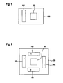
- Figure 1 shows a device 100 for a vehicle assist system according to a first embodiment.
- the device 100 according to the first embodiment comprises a processor 103 and a first receiver 101 adapted to receive a signal.
- Figure 3 depicts part of a vehicle 110.
- the vehicle 110 comprises four first senders 102.
- one or more first senders 102 are identifiable by a preferably unique identification.
- the identification for the individual first sender 102 is a number 1, 2, 3, 4 and the first senders 102 are adapted to send the respective identification in the signal.
- the first receiver 101 is adapted to determine from any received signal the information about the first sender 102 having sent the received signal and to send additional information about the sending first sender 102 to the processor 103.
- the processor 103 is adapted to determine the identification of the sending first sender 102 for each received signal. This way the first sender 102 is identifiable by the identification for each received signal.
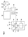
- Figure 2 depicts a device 100 according to a second embodiment.
- the device 100 comprises the processor 103 and four first receivers 101.
- the first receivers 101 are identifiable by a preferably unique identification.
- the identification for the individual first receiver is depicted in Figure 2 as numbers 1, 2, 3, and 4.
- the first receivers 101 are adapted to modify any received signal to add information about the receiver 101 having received the signal, or to send additional information about the receiving first receiver 101 to the processor 103.
- the processor 103 is adapted to determine the identification of the receiving first receiver 101 for each received signal. This way the first receiver 101 is identifiable by the identification for each received signal.
- the device 100 is adapted to be mounted at a road infrastructure and the four first senders 102 are mounted to the vehicle 110.
- the device 100 is adapted to be mounted at the road infrastructure and at least one sender 102 is mounted to the vehicle 110.
- the device 100 is mountable to the vehicle 110 and the at least one first sender 102 is mounted to the road infrastructure.
- the device 100 is mountable to the vehicle 110 and the at least one first sender 102 is mounted to the road infrastructure.
- the first senders 102 are either active sender sending the signal for example at predetermined time intervals.
- the first sender 102 send a beacon signal every 10 milliseconds.
- the first receivers 101 may be passive receivers.
- the first senders 102 comprise an oscillating circuit adapted to respond with the signal upon receipt of a suitable signal.
- the suitable signal is sent by a second sender not depicted.
- the second sender may be either part of the device 100 or external to the device 100.
- the first receiver 101 is designed as a transceiver comprising the first receiver 101 and the second sender.
- the second sender is adapted to send the activation signal at another predetermined time interval, e.g. every 5 milliseconds.
- the first sender 102 and a second receiver not depicted are adapted to act together in order to send the signal upon receipt of the activation signal by the second receiver.
- the first sender 102 is designed as a transceiver comprising the first sender 102 and the second receiver.
- the first sender 102 is adapted to send the signal upon receipt of the activation signal by the second receiver.
- the first senders 102, the second sender, the first receivers 101 and the second receiver are radio frequency identification signal senders and receivers respectively.
- the signal sent or received is a radio frequency identification signal in one of the well known radio frequency identification frequency bands.
- the identification of the first sender 102 in this case is the radio frequency identification of the corresponding first sender 102.
- a passive radio frequency identification tag is used as the first sender 102.
- the second sender is adapted to send the suitable activation signal to activate the radio frequency identification tags within range of the second sender or the first receiver 101.
- the second receiver is adapted to receive the activation signal.
- the oscillating circuit of the radio frequency identification tag is manufactured to comprise the identification of the first sender 102 and send the signal including the information about the identification upon receipt of the activation signal by the second receiver.
- any other type of identification or any other type of signal may be used as well.
- a wireless local area network signal according to the well known IEEE 802.11 standard may be used.
- the processor 103 is adapted to determine a target value for the vehicle assist system from information about a received signal transmitted between the sender and the receiver.
- the information about the received signal may be an indication of the strength of the signal.
- the well known radio signal strengths indication method may be used by the processor 103 to determine the strength of the signal received.
- the radio signal strengths indication is for example a value between 0 and 255, e.g. depending on ratio of the received signal strengths to a predetermined maximum signal strength.
- the radio signal strengths indication 0 indicates that no signal is received.
- increasing values of the radio signal strengths indication indicate a stronger signal with 255 indicating that the received signal is the same as the predetermined maximum signal strength, i.e.
- the ratio is 1.
- the signal strength received is for example determined by the first receiver 101 in Watt and the predetermined maximum strength is stored in the device 100.
- the predetermined maximum strength is the nominal transmission power of the sender in Watt.
- the ratio and the indication of the strength are in this example determined by the processor 103 from this information.
- the processor 103 is adapted to compare the indication of the strength of the received signal to a predetermined reference value.
- the predetermined reference value according to an example is a value between 0 and 255, stored in the device 100.
- the processor is adapted to determine the predetermined reference value depending on the identification of the first sender 102 or the first receiver 101 of the received signal. For example the numbers 1, 2, 3 and 4 identifying the signal also identify the first sender 102 or the first receiver 101 of the received signal. To that end the identification is either determined by the processor 103 from the signal or received from the first receiver 101 as described above.
- the radio frequency identification signals for example the radio frequency identification is used as the identification.
- the processor 103 is adapted to look up the predetermined reference value in a database.
- the predetermined reference value is stored and linked to the identification of the respective first sender 102 or first receiver 101 in the database.
- the predetermined reference value or a particular identification is for example determined in a calibration.
- a calibration is for example performed by placing the first receiver 101 and the first sender 102 at a predetermined position with respect to each other and measuring the signal strengths of the signal transmitted between the first sender 102 and the first receiver 101. In the predetermined position, depending on whether four first senders 102 or four first receivers 101 are used, the signal strength varies, e.g. due to the distance between the respective first senders 102 and the first receivers 101.
- the position of the vehicle 110, in particular of a first charging coil 104 mounted to the vehicle 110, relative to the road infrastructure, in particular a second charging coil mounted to the road infrastructure is selected so that the first charging coil 104 is aligned with the second charging coil to provide an electromagnetic field for most efficient inductive charging, e.g. with minimal loss of energy.
- This position depends on the mounting position of the device 100, in particular the first receivers 101 or the one or more first senders 102 relative to the first or second charging coil or vice versa.
- a calibration method for example comprises of one or multiple repetitions of the following steps in any order:
- the device 100 may furthermore be adapted to compare a number of signals received to a predetermined number.
- the processor 103 counts the number of signals received having different identifications.
- the predetermined number is a value between 0 and 3.
- the number of signals received from different senders or received by different receivers cannot exceed four.
- all of the first receivers 101 either received a signal or a signal sent by all four first senders 102 is received.
- the number of signals is less than four not all of the first receivers 101 received a signal or not all of the signals sent by the first sender 102 are received.
- the processor 103 is used by the processor 103 as an indication for the fact that either one of the four first receivers 101 is out of range of the first sender 102, or one or more of the four first senders 102 is out of range of the first receiver 101.
- the mounting position is in this case stored in a database of the device 100.
- the processor 103 is adapted to determine the relative position of the respective senders or receivers by a geometric calculation. For example the respective orientation and distance of individual first receivers 101 from individual first senders 102 is determined assuming radial signal propagation from the first sender 102.
- the processor 103 is adapted to determine the target value depending on the result of the comparison of either the number of signals received to the predetermined numbers and/or the indication of the strengths of the received signal to the predetermined reference value.
- target value is suitable to control the direction indicated by a parking assist system or to control an inductive charging system.
- a method for a vehicle assist system in particular determining a target value for the vehicle assist system from information about the received signal transmitted between the first sender 102 and the first receiver 101 is explained below making reference to figures 3 to 8 .
- the device 100 is mounted to the road infrastructure and comprises the first receiver 101 and the vehicle 110 comprises four first senders 102.
- Figure 3 schematically depicts part of the vehicle 110.
- the vehicle 110 comprises an inductive charging system with a first inductive charging coil 104.
- the first inductive charging coil 104 is connected to a battery charging System not depicted in Figure 3 .
- the inductive charging system is adapted to charge the battery via the first inductive charging coil 104 when the first inductive charging coil 104 is exposed to a suitable electromagnetic field.
- first senders 102 are mounted to the vehicle 110.
- the four first senders 102 are preferably mounted near the underbody of the vehicle 110 facing downward towards the road when the vehicle on the road.
- the four first senders 102 are installed in a plane that is essentially parallel to the underbody and hence to the road when the vehicle 110 is on the road.
- the mounting position of the four first senders 102 is in this embodiment selected as depicted in Figure 3 .
- the four first senders 102 are for example mounted within the same distance from the origin so that one of the four first senders 102 is mounted on both sides of the origin on each of the axis 121 and 122.
- the alignment of the four first senders 102 may be different. For example the distance of the individual senders to the origin may differ. Furthermore instead of rectangular intersecting axis 121 and 122 any other angle may be selected. According to the example the first axis 121 is aligned to be parallel to the underbody of the vehicle 110 pointing from the rear end of the vehicle to the front of the vehicle essentially following the center line of the vehicle 110 as depicted in Figure 3 . Any other alignment of the first axis 121 may be selected likewise. For example the axis 121 may be diagonally to the rectangle symbolizing the vehicle 110 in Figure 3 . Likewise the second axis 122 may be at any angle to the first axis 121 and hence rotated respective to the vehicle 110 as well.
- first senders 102 are used. This is a preferred embodiment however any other number of first senders 102 may be mounted to the vehicle 110. In particular one, two, three or more than four first senders 102 may be used. In case more than one first sender 102 is used preferably different mounting positions for the individual first senders 102 are selected.
- the first inductive coil 104 and the four first senders 102 are mounted at different positions on the vehicle 110.
- the displacement between the first inductive charging coil 104 and the four first senders 102 may be selected freely.
- the first inductive charging coil 104 and the four first senders 102 are mounted so that the origin, this means the intersection of the first axis 121, and the second axis 122, is located in the center of the first inductive charging coil 104.
- the first axis 121 runs along the center line of the vehicle from the back of the vehicle to the front of the vehicle 110.
- the front of the vehicle is indicated in Figure 3 by an arrow labeled F.
- the arrow F also indicates the forward driving direction of the vehicle 1.10.
- the rear of the vehicle 110 is indicated in Figure 3 as an arrow labeled B. This also indicates the rearward driving direction.
- the left and right side of the vehicle are indicated by respective arrows labeled L and R.
- the arrows labeled L and R also indicate the driving direction left and right of the vehicle 110 respectively.
- the first axis 121 and the second axis 122 and hence the mounting position of the four first senders 102 may be rotated with respect to the vehicle's driving directions.
- the first axis 121 is at an angle regarding the arrow F indicating the forward driving direction
- the second axis 122 may be at an angle to the left and right driving direction as well.
- FIG. 4 depicts part of the vehicle assist system.
- the vehicle assist system comprises of the device 100 and a display 105.
- the display 105 is connectable to the device 100 via a data or signal link.
- the display 105 is adapted to display a target driving direction depending on the target value determined by the device 100.
- the driving directions are indicated as four arrows labeled D1, D2, D3 and D4 in Figure 4 .
- the target value to display the arrows labeled D1, D2, D3 and D4 is D1, D2, D3 and D4 respectively.
- the arrows may be generated as an image on the display 105. Any other kind of displaying methods may be used such as light emitting diodes.
- the display 105 comprises loudspeaker and the directions are indicated sound output of the target driving directions.
- the arrow labeled D1 symbolizes the forward driving direction. Furthermore the arrow labeled D2 symbolizes rearward driving direction. Likewise the arrows labeled D3 and D4 symbolize the left and right driving direction respectively. This is for example either visible from the mounting position of the display 105 with respect to the vehicle 110 or explicitly labeled on the display 105.
- the display 105 is adapted to indicate the driving direction by showing the arrow indicated in the target value.
- one or more arrows may be displayed at the same time.
- the target value (D1, D3) indicates that the arrow D1 and D3 shall be displayed
- the arrows labeled D1 and D3 are displayed. This gives the driver the indication to drive forward and left at the same time.
- Any other type of display of the driving direction may be used as well.
- the driving direction may be indicated by an arrow pointing exactly at the driving direction.
- Figure 5 shows part of a vehicle assist system in particular an inductive charging circuit 106 and the device 100.
- the device 100 and the inductive charging circuit 106 are connectable via a signal or data link.
- the inductive charging circuit 106 is adapted to connect to or disconnect from a power supply.
- the inductive charging circuit 106 is designed as a primary coil generating an electromagnetic field suitable for charging a matching secondary coil.
- this secondary coil is the first charging coil 104 depicted in Figure 3 .
- the inductive charging circuit 106 comprises a second inductive charging coil not depicted in Figure 5 .
- the second inductive charging coil is suitable to charge the vehicle 110 via the first inductive charging coil 104 when the vehicle is parked at a position in which the first inductive coil 104 and the second inductive coil are aligned.
- the alignment in this context means that the relative position of the charging coils is so that an effective electromagnetic energy transfer is possible.
- the inductive charging circuit 106 is adapted to connect the second charging coil to the power supply in case the target value determined by the device 100 indicates that the charging coils are aligned.
- the target value for charging is either "yes" or "no”. This means that the device 100 is adapted to determine the target value to be “yes” in case the two coils are aligned and to the value of "no" in case the two coils are not aligned.
- Figure 6 schematically depicts the vehicle 110 and the vehicle assist system comprising the device 100 the display 105 and the inductive charging circuit 106.
- the device 100 comprises the processor 103 and the first receiver 101.
- the vehicle 110 comprises the four first senders 102 labeled with identifications 1, 2, 3, 4.
- the identifications 1, 2, 3, 4 also indicate the mounting position relative to the origin, i.e. the forward the backward the left and the right driving direction respectively.
- This information and the distance from the origin may be stored in the device 100 during the aforementioned calibration.
- the display 105 is adapted to display the driving direction with the arrows D1, D2, D3, D4 for the forward the rearward the left and the right driving direction respectively.
- the inductive charging circuit 106 is adapted to connect or disconnect the second charging coil to the power supply not depicted. Additionally the first inductive charging coil 104 is adapted to charge the battery of the vehicle 110 when electromagnetic energy is received from the second inductive charging coil.
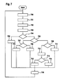
- the method for example starts whenever the device 100 is turned on. After the start a step 700 is executed.
- step 700 the indication of the signal strength is determined for each signal received by the first receiver 101. For example the received signal strength is determined as described above. Afterwards a step 701 is executed.
- step 701 the identification of the sender of the signal is determined for each received signal. For example the radio frequency identification is determined from each received signal. This means that in case a signal is received from the first sender 102 with the identification 1 the determined identification of the sender is 1. Similarly the identification for signals from any other first sender 102 is determined. Step 701 may comprise a wait loop to ensure all available signals are received.
- step 702 is executed.
- step 702 the number of signals received having different identification is determined. This means that in case only the signal from one of the four first senders 102 is received the number of signals received is 1. Likewise and in case several signals are received from the same of the four first senders 102 the number does not increase. This way it is easily determined if only one of the first antennas 102 two, three or all four of the second antennas 102 are within the range of the first antenna 101.
- step 703 is executed.
- step 703 the predetermined reference value linked to the identification is looked up for example in a database comprised in the device 100 for each of the received signals.
- predetermined reference values are for example stored during production of the device 100 in the database.
- the database may be any type of storage.
- the reference values are for example determined in the calibration as described above by placing a vehicle 110 at exactly the best position for inductive charging. This means that the position of the vehicle 110 is placed so that the coils are aligned for best energy transfer via the inductive charging coils. In this position the first receiver 101 and the four first senders 102 are at a defined distance from each other. As depicted in Figure 6 the first antenna 101 is mounted at a certain distance to the inductive charging circuit 106 and hence to the second charging coil. Likewise the four first senders 102 are mounted to the vehicle 110 at a certain distance from the first inductive charging coil 104.
- the first receiver 101 may be located in the center of the second inductive charging coil and/or the four first senders 102 may be located with the origin in the center of the first inductive charging coil 104. In that case the alignment of the inductive charging coils would lead to a position of the first receiver 101 essentially in the origin, i.e. the section point of the first axis 121 and the second axis 122.
- the predetermined reference values for each of the second antennas 102 is determined as a value indicative of the strengths of the signal transmitted between the first antenna 101 and the respective second antenna 102.
- the radio signal strengths indication is determined by the processor 103 from the signal received from the individual antennas 102 as a value between 0 and 255.
- the calibration may be part of the method and may be triggered whenever the device 100 detects that no reference values are stored.
- the display 105 may be adapted to display a text, e.g. calibration, in that case as information for the driver of the vehicle 110.
- step 704 is executed.
- the number of signals received is compared to a first of three predetermined numbers.
- four first senders 102 are used. This means that the predetermined number is 1, 2, or 3. In case more than four first senders 102 are used the predetermined number may be higher. In case for example N first senders 102 are used the predetermined number may be a value between 1 and N - 1. The first predetermined number in the example is 1. The second and third predetermined numbers are 2 and 3 respectively.
- step 704 a test is performed to compare the number of signals received to the first predetermined number to determine if only one signal is received. In case only one signal is received a step 705 is executed otherwise a step 706 is executed.
- step 705 the target value for the direction is determined according to the following table: Table 1 Identification D1 D2 D3 D4 1 x 2 x 3 x 4 x
- the target value for the direction is set to move towards the direction of the first sender 102 sending the received signal.
- the target value for charging is set to "no".
- step 716 is executed.
- step 706 a test is performed to compare the number of signals received to the second predetermined number to test if only two signals are received. In case only two signals are received the step 707 is executed. Otherwise step 708 is executed.
- step 707 a test is performed to determine whether the received signals are sent from first senders 102 of the same axis 121 or 122.
- This means according to the example of Figure 3 in case the received signals are sent from the first senders 102 with the identification 1 or 2 they are on the same axis 121.
- the received signals are sent by the first senders 102 with the identification 3 and 4 they are on the same axis 122.
- a step 709 is executed otherwise a step 710 is executed.
- step 709 the target value for the direction is calculated by a position calculation routine explained later referencing Figure 8 .
- target value for charging is set to "no".
- step 716 is executed.
- step 710 the target value for the direction is determined according to the following table: Table 2 Identification D1 D2 D3 D4 1,3 x x 1,4 x x 2,3 x x 2,4 x x
- the target value for the direction is determined to move towards the direction of the first senders 102 sending the received signal.
- the target value for charging is set to "no".
- step 716 is executed.
- step 708 a test is performed to compare the amount of signals received to the third predetermined number to determine if only 3 signals are received. In case only 3 signals are received a step 711 is executed otherwise a step 712 is executed.
- step 711 the target value for the direction is determined for the first senders 102 located on the same axis by the position calculation routine explained later referencing Figure 8 . Furthermore for the signal received from the first sender 102 not on the same axis the target value for the direction is determined as described in step 705 using table 1.
- the target values of table 1 and the target value that results from the position calculation routine are combined.
- the target value for the direction in this case is set to one of D1, D3; D1, D4; D2, D3; D2, D4 in case the vehicle 110 shall be moved in more than one driving direction.
- the target value for the direction is determined only by the result of the calculation according to step 705 using table 1. This means that in this case the target value for the direction is set to move towards the direction of the first sender 102 not on the same axis as the other two first senders 102.
- target value for charging is set to "no".
- step 716 is executed.
- step 712 the position calculation routine is used twice for each of the axis 121, 122 with the respective first senders 102.
- the target value for the direction is determined depending on the result of the position calculation routine to be one of D1, D3; D1, D4; D2, D3; D2, D4 in case movement in more than one direction is required. Otherwise in case the position calculation routine determines for both axis 121, 122 that the vehicle is already perfectly aligned the target value for the direction is set to an empty value indicating that no movement is required. Furthermore the target value for the direction is set to only one direction D1, D2, D3 or D4 in case movement is only required into one of the directions. Afterwards a step 713 is executed.
- step 713 a test is performed to determine if the indication of the signal strengths is larger or equal to the respective predetermined reference value for each of the first senders 102 respectively. In case the indication of the signal strengths is larger or equal to the respective predetermined reference value a step 714 is executed. Otherwise a step 715 is executed.
- step 714 the target value for charging is set to "yes”. Afterwards a step 716 is executed.
- step 715 the target value for charging is set to "no". Afterwards a step 716 is executed.
- step 716 the target value suitable to control the direction indicated by the parking assist system or to control the inductive charging circuit is issued.
- the target value for charging and the target value for the direction are sent.
- the determined target values may be transformed into control signals suitable to control the display 105 and inductive charging circuit 106 respectively.
- the target value charging "no” is transformed into a signal disconnecting the inductive charging circuit 106 from the power supply.
- the target value for charging "yes” is transformed into a signal to connect the inductive charging circuit 106 to the power supply. Any type of signal like an electronic signal to engage or disengage a switch may be used.
- the direction indications D1 D2, D3 or D4 are transformed to control the direction to be indicated by the display 105.
- electronic signals are used to light up the light emitting diodes corresponding to the direction indication.
- step 700 is executed.
- step 801 a test is performed to determine whether both indications of signal strengths are larger than or equal to the respective reference value. In case both indications of the signal strengths are larger than the respective reference value step 802 is executed. Otherwise a step 803 is executed.
- step 802 the target value for the direction on the axis is set to an empty value. This indicates that the position of the vehicle 110 along the respective axis is aligned well enough for inductive power transfer. In this case the position calculation routine ends and returns the empty target value for the direction.
- step 803 a test is performed to determine if both indications of the signal strengths are smaller than the respective reference value. In case both indications are smaller than the respective reference value a step 804 is executed otherwise a step 806 is executed.
- step 804 the difference between the indication of the signal strengths and the reference value is determined.
- the difference between the indication of the signal strengths and the reference value for the first sender 102 with the identification 1 is labeled dl.
- the other differences are labeled d2, d3 and d4 for the first senders 102 with the identification 2, 3 and 4 respectively.
- a step 805 is executed.
- the target value for the direction indicates to drive in the direction D2.
- the position calculation routine ends and returns the target value for the direction.
- step 806 the target value for the direction is determined according to the following table: Table 4 Identification D1 D2 D3 D4 1 x 2 x 3 x 4 x
- the identification in Table 4 is the identification of the sender of the received signal that has a signal strength smaller than the predetermined reference value.
- the target value for the direction is set to the respective information about the direction depending on the identification of the signal that has a smaller value than the predetermined reference value. Afterwards the position calculation routine ends and returns to target value for the direction.
- the vehicle 110 comprises four first senders 102 with the different identifications 1, 2, 3 and 4.
- radio frequency identification tags may be used for the first senders 102.
- the radio frequency identification resembles the identification 1, 2, 3 and 4 of the respective first senders 102.
- the first receiver 101 is adapted to receive the radio frequency signals and the identification from the first senders 102.
- the processor 103 is adapted to determine the radio frequency identification from the signals. This means that in this case the identification is the identification of the sender of the signal.
- the device 100 comprises according to the second embodiment four first receivers 101 and the processor 103 as depicted in Figure 2 .
- the vehicle 110 may be equipped with one first sender 102.
- active or passive radio frequency identification antennas may be used.
- the device 100 is installed on the vehicle 110 the entire vehicle assist system may be installed on the vehicle.
- the display 105 is not installed on the vehicle 110 an additional data link between the device 100 mounted on the vehicle and the display 105 may be provided in order to transmit the target value for the direction.
- an additional data link may be provided between the device 100 and the inductive charging system 106 in order to transfer the target value determined by the device 100 for charging to the inductive charging system 106 in order to initiate the inductive charging when the aforementioned method is executed.
- the device 100 may comprise of the required interface for example a wireless local area network interface according to the well known IEEE 802.11 standard.
- the transceivers of the third and fourth embodiment may be used to send a request in an additional step of the method, e.g. before step 700.
- the second sender may be adapted to send the request to trigger the radio frequency identification tag in this additional step.
- the second receiver may receive the request and the first sender 102 is adapted to respond by sending the signal preferably comprising the identification of the radio frequency identification tag upon receipt of this request by the second receiver.
- the charging may be disrupted whenever the battery of the vehicle 110 is fully charged or when the displacement of the two inductive charging coils exceeds a maximum value.
- the method described above may comprise an additional step to detect either that the battery is fully charged or that the displacement of the inductive charging coils is too large.
- the target value for the direction may be monitored and the displacement may be detected whenever the target value for the direction is not empty anymore.
- the battery stages or energy flow wire inductive charging circuit may be monitored.
- any functional blocks labeled as 'processors' may be provided through the use of dedicated hardware as well as hardware capable of executing software in association with appropriate software.
- the functions may be provided by a single dedicated processor, by a single shared processor, or by a plurality of individual processors, some of which may be shared.
- explicit use of the term 'processor' or 'controller' should not be construed to refer exclusively to hardware capable of executing software, and may implicitly include, without limitation, digital signal processor (DSP) hardware, network processor, application specific integrated circuit (ASIC), field programmable gate array (FPGA), read only memory (ROM) for storing software, random access memory (RAM), and non volatile storage.
- DSP digital signal processor
- ASIC application specific integrated circuit
- FPGA field programmable gate array
- ROM read only memory
- RAM random access memory
- any switches shown in the figures are conceptual only. Their function may be carried out through the operation of program logic, through dedicated logic, through the interaction of program control and dedicated logic, or even manually, the particular technique being selectable by the implementer as more specifically understood from the context.
- program storage devices e.g., digital data storage media, which are machine or computer readable and encode machine-executable or computer-executable programs of instructions, wherein said instructions perform some or all of the steps of said above-described methods.
- the program storage devices may be, e.g., digital memories, magnetic storage media such as a magnetic disks and magnetic tapes, hard drives, or optically readable digital data storage media.
- the embodiments are also intended to cover computers programmed to perform said steps of the above-described methods.
Landscapes
- Engineering & Computer Science (AREA)
- Power Engineering (AREA)
- Transportation (AREA)
- Mechanical Engineering (AREA)
- Electric Propulsion And Braking For Vehicles (AREA)
Abstract
Description
- The invention relates to a method and a device for a vehicle assist system in particular a parking assist system or an inductive charging system.
- Vehicle assist systems for assisting a driver of a vehicle to park the vehicle for example use ultrasound sensors to detect obstacles such as neighboring vehicles and guide the driver into a parking position. However, such systems do not indicate a target position with sufficient precision. Highly precise parking systems or inductive charging systems require a highly accurate positioning of the vehicle or the involved inductive charging coils relative to each other.
- The object of the invention is thus to provide a device for a vehicle assist system and a method for such vehicle assist system having the precision for parking required in particular by an inductive charging systems. Furthermore an object is to assist in initiating the inductive charging when the position of the vehicle assisted is correct.
- The main idea of the invention is to determine a target value for the vehicle assist system from information about a received signal transmitted between a sender and a receiver.
- Advantageously the information about the received signal is an indication of the strength of the signal. This way the precision required by the parking assist system or the inductive charging system can be reached easily. Furthermore cheap components such as radio frequency identification devices can be used to implement the system.
- Advantageously the indication of the strengths of the received signal is compared to a predetermined reference value. This way it is possible to determine the reference values once for example during production of a vehicle, the parking assist system or the inductive charging system and reuse predetermined reference values. This reduces cost of manufacture and increases the flexibility.
- Advantageously the predetermined reference value is determined depending on an identification of the sender or receiver of the signal. This allows distinction between different senders or receivers and therefore increases the precision.
- Advantageously a number of signals received is compared to a predetermined number. This increases robustness in particular when several signals are received.
- Advantageously the target value is determined depending on the result of the comparison of the indication of the strength of the received signal to the predetermined reference value or the number of signals received to the predetermined number. This provides for a reliable and robust solution.
- Advantageously the target value is suitable to control the direction indicated by a parking assist system or to control an inductive charging system. This way the target values can be used directly by parking assist systems or inductive charging systems. This makes integration of the inductive charging system much simpler.
- Further developments of the invention can be gathered from the dependant claims, the method claims and the following description.
- In the following the invention will be explained further making reference to the attached drawings.
-
Figure 1 schematically shows an embodiment of a device for a vehicle assist system. -
Figure 2 schematically shows another embodiment of a device for a vehicle assist system. -
Figure 3 schematically shows part of a vehicle. -
Figure 4 schematically shows a part of a vehicle assist system. -
Figure 5 schematically shows a part of a vehicle assist system. -
Figure 6 schematically shows a vehicle and a part of a vehicle assist system. -
Figure 7 schematically shows a flow chart of part of a method. -
Figure 8 schematically shows a flow chart of part of a method. -
Figure 1 shows adevice 100 for a vehicle assist system according to a first embodiment. Thedevice 100 according to the first embodiment comprises aprocessor 103 and afirst receiver 101 adapted to receive a signal. -
Figure 3 depicts part of avehicle 110. According to the first embodiment thevehicle 110 comprises fourfirst senders 102. According to the first embodiment one or morefirst senders 102 are identifiable by a preferably unique identification. In the example the identification for the individualfirst sender 102 is anumber first senders 102 are adapted to send the respective identification in the signal. - Furthermore the
first receiver 101 is adapted to determine from any received signal the information about thefirst sender 102 having sent the received signal and to send additional information about the sendingfirst sender 102 to theprocessor 103. Alternatively theprocessor 103 is adapted to determine the identification of the sendingfirst sender 102 for each received signal. This way thefirst sender 102 is identifiable by the identification for each received signal. -
Figure 2 depicts adevice 100 according to a second embodiment. According to the second embodiment thedevice 100 comprises theprocessor 103 and fourfirst receivers 101. Thefirst receivers 101 are identifiable by a preferably unique identification. In the example the identification for the individual first receiver is depicted inFigure 2 asnumbers first receivers 101 are adapted to modify any received signal to add information about thereceiver 101 having received the signal, or to send additional information about the receivingfirst receiver 101 to theprocessor 103. Alternatively theprocessor 103 is adapted to determine the identification of the receivingfirst receiver 101 for each received signal. This way thefirst receiver 101 is identifiable by the identification for each received signal. - According to the first embodiment, the
device 100 is adapted to be mounted at a road infrastructure and the fourfirst senders 102 are mounted to thevehicle 110. - According to the second embodiment, the
device 100 is adapted to be mounted at the road infrastructure and at least onesender 102 is mounted to thevehicle 110. - According to a third embodiment not depicted, the
device 100 according to the first embodiment is mountable to thevehicle 110 and the at least onefirst sender 102 is mounted to the road infrastructure. - According to a fourth embodiment not depicted, the
device 100 according to the second embodiment is mountable to thevehicle 110 and the at least onefirst sender 102 is mounted to the road infrastructure. - The
first senders 102 are either active sender sending the signal for example at predetermined time intervals. For example thefirst sender 102 send a beacon signal every 10 milliseconds. In this case thefirst receivers 101 may be passive receivers. Alternatively thefirst senders 102 comprise an oscillating circuit adapted to respond with the signal upon receipt of a suitable signal. In this case the suitable signal is sent by a second sender not depicted. The second sender may be either part of thedevice 100 or external to thedevice 100. Preferably thefirst receiver 101 is designed as a transceiver comprising thefirst receiver 101 and the second sender. In any case the second sender is adapted to send the activation signal at another predetermined time interval, e.g. every 5 milliseconds. Furthermore in case a second sender is used, thefirst sender 102 and a second receiver not depicted are adapted to act together in order to send the signal upon receipt of the activation signal by the second receiver. Preferably thefirst sender 102 is designed as a transceiver comprising thefirst sender 102 and the second receiver. In any case thefirst sender 102 is adapted to send the signal upon receipt of the activation signal by the second receiver. - For example the
first senders 102, the second sender, thefirst receivers 101 and the second receiver are radio frequency identification signal senders and receivers respectively. In this case the signal sent or received is a radio frequency identification signal in one of the well known radio frequency identification frequency bands. Furthermore the identification of thefirst sender 102 in this case is the radio frequency identification of the correspondingfirst sender 102. - Preferably a passive radio frequency identification tag is used as the
first sender 102. In this case the second sender is adapted to send the suitable activation signal to activate the radio frequency identification tags within range of the second sender or thefirst receiver 101. In this case the second receiver is adapted to receive the activation signal. Furthermore the oscillating circuit of the radio frequency identification tag is manufactured to comprise the identification of thefirst sender 102 and send the signal including the information about the identification upon receipt of the activation signal by the second receiver. - Any other type of identification or any other type of signal may be used as well. For example a wireless local area network signal according to the well known IEEE 802.11 standard may be used.
- According to all embodiments for example the
processor 103 is adapted to determine a target value for the vehicle assist system from information about a received signal transmitted between the sender and the receiver. In particular the information about the received signal may be an indication of the strength of the signal. For example the well known radio signal strengths indication method may be used by theprocessor 103 to determine the strength of the signal received. According to an example the radio signal strengths indication is for example a value between 0 and 255, e.g. depending on ratio of the received signal strengths to a predetermined maximum signal strength. According to this example the radio signal strengths indication 0 indicates that no signal is received. According to this example increasing values of the radio signal strengths indication indicate a stronger signal with 255 indicating that the received signal is the same as the predetermined maximum signal strength, i.e. the ratio is 1. The signal strength received is for example determined by thefirst receiver 101 in Watt and the predetermined maximum strength is stored in thedevice 100. For example the predetermined maximum strength is the nominal transmission power of the sender in Watt. The ratio and the indication of the strength are in this example determined by theprocessor 103 from this information. - Furthermore the
processor 103 is adapted to compare the indication of the strength of the received signal to a predetermined reference value. The predetermined reference value according to an example is a value between 0 and 255, stored in thedevice 100. - Furthermore the processor is adapted to determine the predetermined reference value depending on the identification of the
first sender 102 or thefirst receiver 101 of the received signal. For example thenumbers first sender 102 or thefirst receiver 101 of the received signal. To that end the identification is either determined by theprocessor 103 from the signal or received from thefirst receiver 101 as described above. In the example of radio frequency identification signals for example the radio frequency identification is used as the identification. - Furthermore the
processor 103 is adapted to look up the predetermined reference value in a database. To that end the predetermined reference value is stored and linked to the identification of the respectivefirst sender 102 orfirst receiver 101 in the database. The predetermined reference value or a particular identification is for example determined in a calibration. A calibration is for example performed by placing thefirst receiver 101 and thefirst sender 102 at a predetermined position with respect to each other and measuring the signal strengths of the signal transmitted between thefirst sender 102 and thefirst receiver 101. In the predetermined position, depending on whether fourfirst senders 102 or fourfirst receivers 101 are used, the signal strength varies, e.g. due to the distance between the respectivefirst senders 102 and thefirst receivers 101. In the calibration preferably the position of thevehicle 110, in particular of afirst charging coil 104 mounted to thevehicle 110, relative to the road infrastructure, in particular a second charging coil mounted to the road infrastructure is selected so that thefirst charging coil 104 is aligned with the second charging coil to provide an electromagnetic field for most efficient inductive charging, e.g. with minimal loss of energy. This position depends on the mounting position of thedevice 100, in particular thefirst receivers 101 or the one or morefirst senders 102 relative to the first or second charging coil or vice versa. A calibration method for example comprises of one or multiple repetitions of the following steps in any order: - parking the
vehicle 110 at the appropriate position relative to the road infrastructure, e.g. so that thefirst charging coil 104 is aligned with the second charging coil, - sending by a
first sender 102 the signal with a predetermined strength, e.g. 10 mW, - receiving the signal,
- determining the strength of the received signal by measurement, e.g. 2 mW,
- determine the identification of either the
first sender 102 or thefirst receiver 101 for the received signal, e.g. 2, - determining the indication of the signal strength from the received signal and the predetermined strength, e.g. according to the following calculation: 255*2mW/10mW = 51,
- storing the indication of the signal strength as predetermined reference value in the database linked to the identification of the
first sender 102 or thefirst receiver 101, e.g. as data pair (51, 2). - The
device 100 may furthermore be adapted to compare a number of signals received to a predetermined number. To that end theprocessor 103 counts the number of signals received having different identifications. Furthermore according to the example the predetermined number is a value between 0 and 3. In the example of four identifiablefirst senders 102 or fourfirst receivers 101 the number of signals received from different senders or received by different receivers cannot exceed four. In case the number of signals received from different senders or receivers is four, all of thefirst receivers 101 either received a signal or a signal sent by all fourfirst senders 102 is received. In case the number of signals is less than four not all of thefirst receivers 101 received a signal or not all of the signals sent by thefirst sender 102 are received. This is used by theprocessor 103 as an indication for the fact that either one of the fourfirst receivers 101 is out of range of thefirst sender 102, or one or more of the fourfirst senders 102 is out of range of thefirst receiver 101. This way an indication of the relative position of thefirst sender 102 and thefirst receiver 101 is determined, depending on the mounting position of the respective sender or receiver without comparison to the predetermined reference value. The mounting position is in this case stored in a database of thedevice 100. For example the mounting position of the fourfirst senders 102 or the fourfirst receivers 101 relative to an origin of a coordinate system is stored. In this case theprocessor 103 is adapted to determine the relative position of the respective senders or receivers by a geometric calculation. For example the respective orientation and distance of individualfirst receivers 101 from individualfirst senders 102 is determined assuming radial signal propagation from thefirst sender 102. - Furthermore the
processor 103 is adapted to determine the target value depending on the result of the comparison of either the number of signals received to the predetermined numbers and/or the indication of the strengths of the received signal to the predetermined reference value. - Furthermore the target value is suitable to control the direction indicated by a parking assist system or to control an inductive charging system.
- A method for a vehicle assist system in particular determining a target value for the vehicle assist system from information about the received signal transmitted between the
first sender 102 and thefirst receiver 101 is explained below making reference tofigures 3 to 8 . - The method is described according to the first embodiment, i.e. the
device 100 is mounted to the road infrastructure and comprises thefirst receiver 101 and thevehicle 110 comprises fourfirst senders 102. -
Figure 3 schematically depicts part of thevehicle 110. AccordingFigure 3 thevehicle 110 comprises an inductive charging system with a firstinductive charging coil 104. The firstinductive charging coil 104 is connected to a battery charging System not depicted inFigure 3 . The inductive charging system is adapted to charge the battery via the firstinductive charging coil 104 when the firstinductive charging coil 104 is exposed to a suitable electromagnetic field. - Furthermore according to this embodiment four
first senders 102 are mounted to thevehicle 110. The fourfirst senders 102 are preferably mounted near the underbody of thevehicle 110 facing downward towards the road when the vehicle on the road. According to this embodiment the fourfirst senders 102 are installed in a plane that is essentially parallel to the underbody and hence to the road when thevehicle 110 is on the road. - The mounting position of the four
first senders 102 is in this embodiment selected as depicted inFigure 3 . Considering afirst axis 121 and asecond axis 122 intersecting rectangular in an origin the fourfirst senders 102 are for example mounted within the same distance from the origin so that one of the fourfirst senders 102 is mounted on both sides of the origin on each of theaxis - The alignment of the four
first senders 102 may be different. For example the distance of the individual senders to the origin may differ. Furthermore instead ofrectangular intersecting axis first axis 121 is aligned to be parallel to the underbody of thevehicle 110 pointing from the rear end of the vehicle to the front of the vehicle essentially following the center line of thevehicle 110 as depicted inFigure 3 . Any other alignment of thefirst axis 121 may be selected likewise. For example theaxis 121 may be diagonally to the rectangle symbolizing thevehicle 110 inFigure 3 . Likewise thesecond axis 122 may be at any angle to thefirst axis 121 and hence rotated respective to thevehicle 110 as well. - According to the example four
first senders 102 are used. This is a preferred embodiment however any other number offirst senders 102 may be mounted to thevehicle 110. In particular one, two, three or more than fourfirst senders 102 may be used. In case more than onefirst sender 102 is used preferably different mounting positions for the individualfirst senders 102 are selected. - According to the embodiment the first
inductive coil 104 and the fourfirst senders 102 are mounted at different positions on thevehicle 110. The displacement between the firstinductive charging coil 104 and the fourfirst senders 102 may be selected freely. Preferably the firstinductive charging coil 104 and the fourfirst senders 102 are mounted so that the origin, this means the intersection of thefirst axis 121, and thesecond axis 122, is located in the center of the firstinductive charging coil 104. - As depicted in
Figure 3 thefirst axis 121 runs along the center line of the vehicle from the back of the vehicle to the front of thevehicle 110. The front of the vehicle is indicated inFigure 3 by an arrow labeled F. The arrow F also indicates the forward driving direction of the vehicle 1.10. The rear of thevehicle 110 is indicated inFigure 3 as an arrow labeled B. This also indicates the rearward driving direction. Likewise the left and right side of the vehicle are indicated by respective arrows labeled L and R. The arrows labeled L and R also indicate the driving direction left and right of thevehicle 110 respectively. - The
first axis 121 and thesecond axis 122 and hence the mounting position of the fourfirst senders 102 may be rotated with respect to the vehicle's driving directions. In this case thefirst axis 121 is at an angle regarding the arrow F indicating the forward driving direction likewise thesecond axis 122 may be at an angle to the left and right driving direction as well. -
Figure 4 depicts part of the vehicle assist system. The vehicle assist system comprises of thedevice 100 and adisplay 105. Thedisplay 105 is connectable to thedevice 100 via a data or signal link. Thedisplay 105 is adapted to display a target driving direction depending on the target value determined by thedevice 100. For example the driving directions are indicated as four arrows labeled D1, D2, D3 and D4 inFigure 4 . In this case for example the target value to display the arrows labeled D1, D2, D3 and D4 is D1, D2, D3 and D4 respectively. The arrows may be generated as an image on thedisplay 105. Any other kind of displaying methods may be used such as light emitting diodes. Additionally or alternatively thedisplay 105 comprises loudspeaker and the directions are indicated sound output of the target driving directions. - According to the embodiment the arrow labeled D1 symbolizes the forward driving direction. Furthermore the arrow labeled D2 symbolizes rearward driving direction. Likewise the arrows labeled D3 and D4 symbolize the left and right driving direction respectively. This is for example either visible from the mounting position of the
display 105 with respect to thevehicle 110 or explicitly labeled on thedisplay 105. - The
display 105 is adapted to indicate the driving direction by showing the arrow indicated in the target value. According to the example one or more arrows may be displayed at the same time. For example in case the target value (D1, D3) indicates that the arrow D1 and D3 shall be displayed, the arrows labeled D1 and D3 are displayed. This gives the driver the indication to drive forward and left at the same time. Any other type of display of the driving direction may be used as well. In particular the driving direction may be indicated by an arrow pointing exactly at the driving direction. -
Figure 5 shows part of a vehicle assist system in particular aninductive charging circuit 106 and thedevice 100. Thedevice 100 and theinductive charging circuit 106 are connectable via a signal or data link. Theinductive charging circuit 106 is adapted to connect to or disconnect from a power supply. In the example theinductive charging circuit 106 is designed as a primary coil generating an electromagnetic field suitable for charging a matching secondary coil. In the example this secondary coil is thefirst charging coil 104 depicted inFigure 3 . Theinductive charging circuit 106 comprises a second inductive charging coil not depicted inFigure 5 . The second inductive charging coil is suitable to charge thevehicle 110 via the firstinductive charging coil 104 when the vehicle is parked at a position in which the firstinductive coil 104 and the second inductive coil are aligned. The alignment in this context means that the relative position of the charging coils is so that an effective electromagnetic energy transfer is possible. Theinductive charging circuit 106 is adapted to connect the second charging coil to the power supply in case the target value determined by thedevice 100 indicates that the charging coils are aligned. For example the target value for charging is either "yes" or "no". This means that thedevice 100 is adapted to determine the target value to be "yes" in case the two coils are aligned and to the value of "no" in case the two coils are not aligned. -
Figure 6 schematically depicts thevehicle 110 and the vehicle assist system comprising thedevice 100 thedisplay 105 and theinductive charging circuit 106. According to the example thedevice 100 comprises theprocessor 103 and thefirst receiver 101. Furthermore thevehicle 110 comprises the fourfirst senders 102 labeled withidentifications identifications - This information and the distance from the origin may be stored in the
device 100 during the aforementioned calibration. - Furthermore the
display 105 is adapted to display the driving direction with the arrows D1, D2, D3, D4 for the forward the rearward the left and the right driving direction respectively. - Furthermore the
inductive charging circuit 106 is adapted to connect or disconnect the second charging coil to the power supply not depicted. Additionally the firstinductive charging coil 104 is adapted to charge the battery of thevehicle 110 when electromagnetic energy is received from the second inductive charging coil. - A part of the method for the vehicle assist system is explained now making reference to
Figure 7 . The method for example starts whenever thedevice 100 is turned on. After the start astep 700 is executed. - In
step 700 the indication of the signal strength is determined for each signal received by thefirst receiver 101. For example the received signal strength is determined as described above. Afterwards astep 701 is executed. - In
step 701 the identification of the sender of the signal is determined for each received signal. For example the radio frequency identification is determined from each received signal. This means that in case a signal is received from thefirst sender 102 with theidentification 1 the determined identification of the sender is 1. Similarly the identification for signals from any otherfirst sender 102 is determined. Step 701 may comprise a wait loop to ensure all available signals are received. - Afterwards a
step 702 is executed. - In
step 702 the number of signals received having different identification is determined. This means that in case only the signal from one of the fourfirst senders 102 is received the number of signals received is 1. Likewise and in case several signals are received from the same of the fourfirst senders 102 the number does not increase. This way it is easily determined if only one of thefirst antennas 102 two, three or all four of thesecond antennas 102 are within the range of thefirst antenna 101. - Afterwards a
step 703 is executed. - In
step 703 the predetermined reference value linked to the identification is looked up for example in a database comprised in thedevice 100 for each of the received signals. To that end predetermined reference values are for example stored during production of thedevice 100 in the database. The database may be any type of storage. - The reference values are for example determined in the calibration as described above by placing a
vehicle 110 at exactly the best position for inductive charging. This means that the position of thevehicle 110 is placed so that the coils are aligned for best energy transfer via the inductive charging coils. In this position thefirst receiver 101 and the fourfirst senders 102 are at a defined distance from each other. As depicted inFigure 6 thefirst antenna 101 is mounted at a certain distance to theinductive charging circuit 106 and hence to the second charging coil. Likewise the fourfirst senders 102 are mounted to thevehicle 110 at a certain distance from the firstinductive charging coil 104. Alternatively thefirst receiver 101 may be located in the center of the second inductive charging coil and/or the fourfirst senders 102 may be located with the origin in the center of the firstinductive charging coil 104. In that case the alignment of the inductive charging coils would lead to a position of thefirst receiver 101 essentially in the origin, i.e. the section point of thefirst axis 121 and thesecond axis 122. In any case the predetermined reference values for each of thesecond antennas 102 is determined as a value indicative of the strengths of the signal transmitted between thefirst antenna 101 and the respectivesecond antenna 102. For example the radio signal strengths indication is determined by theprocessor 103 from the signal received from theindividual antennas 102 as a value between 0 and 255. This value is then stored during calibration as predetermined reference value linked to the identification of the respectivesecond antenna 102 in the database. The calibration may be part of the method and may be triggered whenever thedevice 100 detects that no reference values are stored. Thedisplay 105 may be adapted to display a text, e.g. calibration, in that case as information for the driver of thevehicle 110. - Afterwards a
step 704 is executed. - In 704 the number of signals received is compared to a first of three predetermined numbers. In the example four
first senders 102 are used. This means that the predetermined number is 1, 2, or 3. In case more than fourfirst senders 102 are used the predetermined number may be higher. In case for example Nfirst senders 102 are used the predetermined number may be a value between 1 and N - 1. The first predetermined number in the example is 1. The second and third predetermined numbers are 2 and 3 respectively. - This way in step 704 a test is performed to compare the number of signals received to the first predetermined number to determine if only one signal is received. In case only one signal is received a
step 705 is executed otherwise astep 706 is executed. - In
step 705 the target value for the direction is determined according to the following table:Table 1 Identification D1 D2 D3 D4 1 x 2 x 3 x 4 x - This means that the target value for the direction is set to move towards the direction of the
first sender 102 sending the received signal. - The target value for charging is set to "no".
- Afterwards a
step 716 is executed. - In step 706 a test is performed to compare the number of signals received to the second predetermined number to test if only two signals are received. In case only two signals are received the
step 707 is executed. Otherwise step 708 is executed. - In step 707 a test is performed to determine whether the received signals are sent from
first senders 102 of thesame axis Figure 3 , in case the received signals are sent from thefirst senders 102 with theidentification same axis 121. Likewise in the example in case the received signals are sent by thefirst senders 102 with theidentification same axis 122. In case the received signals are fromfirst senders 102 on the same axis astep 709 is executed otherwise astep 710 is executed. - In
step 709 the target value for the direction is calculated by a position calculation routine explained later referencingFigure 8 . - Furthermore the target value for charging is set to "no".
- Afterwards a
step 716 is executed. - In
step 710 the target value for the direction is determined according to the following table:Table 2 Identification D1 D2 D3 D4 1,3 x x 1,4 x x 2,3 x x 2,4 x x - This means that the target value for the direction is determined to move towards the direction of the
first senders 102 sending the received signal. - The target value for charging is set to "no".
- Afterwards a
step 716 is executed. - In step 708 a test is performed to compare the amount of signals received to the third predetermined number to determine if only 3 signals are received. In case only 3 signals are received a
step 711 is executed otherwise astep 712 is executed. - In case N
first senders 102 are used, the tests described insteps - In
step 711 the target value for the direction is determined for thefirst senders 102 located on the same axis by the position calculation routine explained later referencingFigure 8 . Furthermore for the signal received from thefirst sender 102 not on the same axis the target value for the direction is determined as described instep 705 using table 1. - Afterwards the target values of table 1 and the target value that results from the position calculation routine are combined. According to the example the target value for the direction in this case is set to one of D1, D3; D1, D4; D2, D3; D2, D4 in case the
vehicle 110 shall be moved in more than one driving direction. In case the result of the position calculation routine indicates that the position of the vehicle along the axis is already sufficiently aligned, the target value for the direction is determined only by the result of the calculation according to step 705 using table 1. This means that in this case the target value for the direction is set to move towards the direction of thefirst sender 102 not on the same axis as the other twofirst senders 102. - Furthermore the target value for charging is set to "no".
- Afterwards a
step 716 is executed. - In
step 712 the position calculation routine is used twice for each of theaxis first senders 102. As instep 711 the target value for the direction is determined depending on the result of the position calculation routine to be one of D1, D3; D1, D4; D2, D3; D2, D4 in case movement in more than one direction is required. Otherwise in case the position calculation routine determines for bothaxis step 713 is executed. - In step 713 a test is performed to determine if the indication of the signal strengths is larger or equal to the respective predetermined reference value for each of the
first senders 102 respectively. In case the indication of the signal strengths is larger or equal to the respective predetermined reference value astep 714 is executed. Otherwise astep 715 is executed. - In
step 714 the target value for charging is set to "yes". Afterwards astep 716 is executed. - In
step 715 the target value for charging is set to "no". Afterwards astep 716 is executed. - In
step 716 the target value suitable to control the direction indicated by the parking assist system or to control the inductive charging circuit is issued. For example the target value for charging and the target value for the direction are sent. Alternatively the determined target values may be transformed into control signals suitable to control thedisplay 105 andinductive charging circuit 106 respectively. For example the target value charging "no" is transformed into a signal disconnecting theinductive charging circuit 106 from the power supply. Likewise the target value for charging "yes" is transformed into a signal to connect theinductive charging circuit 106 to the power supply. Any type of signal like an electronic signal to engage or disengage a switch may be used. - Likewise in order to control the
display 105 the direction indications D1 D2, D3 or D4 are transformed to control the direction to be indicated by thedisplay 105. For example electronic signals are used to light up the light emitting diodes corresponding to the direction indication. - Afterwards the
step 700 is executed. - The position calculation routine mentioned above is now explained making reference to
Figure 8 . - After the start a
step 801 is executed. - In step 801 a test is performed to determine whether both indications of signal strengths are larger than or equal to the respective reference value. In case both indications of the signal strengths are larger than the respective
reference value step 802 is executed. Otherwise astep 803 is executed. - In
step 802 the target value for the direction on the axis is set to an empty value. This indicates that the position of thevehicle 110 along the respective axis is aligned well enough for inductive power transfer. In this case the position calculation routine ends and returns the empty target value for the direction. - In step 803 a test is performed to determine if both indications of the signal strengths are smaller than the respective reference value. In case both indications are smaller than the respective reference value a
step 804 is executed otherwise a step 806 is executed. - In
step 804 the difference between the indication of the signal strengths and the reference value is determined. The difference between the indication of the signal strengths and the reference value for thefirst sender 102 with theidentification 1 is labeled dl. Likewise the other differences are labeled d2, d3 and d4 for thefirst senders 102 with theidentification step 805 is executed. - In
step 805 the target value for the direction is determined according to the following table:Table 3 Signal strengths relation D1 D2 D3 D4 d1 > d2 x d1 < d2 x d3 > d4 x d3 < d4 x d1 = d2 d3 = d4 - This way the direction information is determined depending on the difference between the indication of the signal strengths and the predetermined reference values.
- Assuming 200 and 100 as the predetermined reference values for the
second antennas 102 with theidentification first senders 102 with theidentification first sender 102 with theidentification 1 is closer to thefirst receiver 101 as thefirst sender 102 with theidentification 2. Furthermore this means that the difference between the indication of the signal strengths of the received signal and the respective predetermined reference value indicates that the distance of thefirst sender 102 with theidentification 1 to the best position for charging the vehicle inductively is 200 - 75 = 125 and thus larger than the distance of thefirst sender 102 with theidentification 2 that is at 100 - 25 = 75. In this case according to table 3 the target value for the direction indicates to drive in the direction D2. - Afterwards the position calculation routine ends and returns the target value for the direction.
- In step 806 the target value for the direction is determined according to the following table:
Table 4 Identification D1 D2 D3 D4 1 x 2 x 3 x 4 x - The identification in Table 4 is the identification of the sender of the received signal that has a signal strength smaller than the predetermined reference value.
- The target value for the direction is set to the respective information about the direction depending on the identification of the signal that has a smaller value than the predetermined reference value. Afterwards the position calculation routine ends and returns to target value for the direction.
- The method was described above for an embodiment having the
device 100 withfirst receiver 101 and theprocessor 103. In this example thevehicle 110 comprises fourfirst senders 102 with thedifferent identifications first senders 102. In this case the radio frequency identification resembles theidentification first senders 102. Furthermore in this case thefirst receiver 101 is adapted to receive the radio frequency signals and the identification from thefirst senders 102. Furthermore theprocessor 103 is adapted to determine the radio frequency identification from the signals. This means that in this case the identification is the identification of the sender of the signal. - The method applies likewise to the other embodiment of the invention.
- For example the
device 100 comprises according to the second embodiment fourfirst receivers 101 and theprocessor 103 as depicted inFigure 2 . According to this example thevehicle 110 may be equipped with onefirst sender 102. - In the examples active or passive radio frequency identification antennas may be used. In particular this means that according to the examples it is not essential whether the
device 100 installed on thevehicle 110 or at the road infrastructure. In case thedevice 100 is installed on thevehicle 110 the entire vehicle assist system may be installed on the vehicle. In case thedisplay 105 is not installed on thevehicle 110 an additional data link between thedevice 100 mounted on the vehicle and thedisplay 105 may be provided in order to transmit the target value for the direction. - Furthermore in this case an additional data link may be provided between the
device 100 and theinductive charging system 106 in order to transfer the target value determined by thedevice 100 for charging to theinductive charging system 106 in order to initiate the inductive charging when the aforementioned method is executed. - To this end the
device 100 may comprise of the required interface for example a wireless local area network interface according to the well known IEEE 802.11 standard. - To trigger sending of the signal between the
first sender 102 and thefirst receiver 101 the transceivers of the third and fourth embodiment may be used to send a request in an additional step of the method, e.g. beforestep 700. For example in case radio frequency identification tags are used as thefirst senders 102 the second sender may be adapted to send the request to trigger the radio frequency identification tag in this additional step. In another additional step in this case the second receiver may receive the request and thefirst sender 102 is adapted to respond by sending the signal preferably comprising the identification of the radio frequency identification tag upon receipt of this request by the second receiver. - Optionally at any time during the aforementioned methods the charging may be disrupted whenever the battery of the
vehicle 110 is fully charged or when the displacement of the two inductive charging coils exceeds a maximum value. To that end the method described above may comprise an additional step to detect either that the battery is fully charged or that the displacement of the inductive charging coils is too large. In order to detect the displacement for example the target value for the direction may be monitored and the displacement may be detected whenever the target value for the direction is not empty anymore. Furthermore to detect that the battery is fully charged the battery stages or energy flow wire inductive charging circuit may be monitored. - The description and drawings merely illustrate the principles of the invention. It will thus be appreciated that those skilled in the art will be able to devise various arrangements that, although not explicitly described or shown herein, embody the principles of the invention and are included within its spirit and scope. Furthermore, all examples recited herein are principally intended expressly to be only for pedagogical purposes to aid the reader in understanding the principles of the invention and the concepts contributed by the inventor(s) to furthering the art, and are to be construed as being without limitation to such specifically recited examples and conditions. Moreover, all statements herein reciting principles, aspects, and embodiments of the invention, as well as specific examples thereof, are intended to encompass equivalents thereof.
- The functions of the various elements shown in the figures, including any functional blocks labeled as 'processors', may be provided through the use of dedicated hardware as well as hardware capable of executing software in association with appropriate software. When provided by a processor, the functions may be provided by a single dedicated processor, by a single shared processor, or by a plurality of individual processors, some of which may be shared. Moreover, explicit use of the term 'processor' or 'controller' should not be construed to refer exclusively to hardware capable of executing software, and may implicitly include, without limitation, digital signal processor (DSP) hardware, network processor, application specific integrated circuit (ASIC), field programmable gate array (FPGA), read only memory (ROM) for storing software, random access memory (RAM), and non volatile storage. Other hardware, conventional and/or custom, may also be included. Similarly, any switches shown in the figures are conceptual only. Their function may be carried out through the operation of program logic, through dedicated logic, through the interaction of program control and dedicated logic, or even manually, the particular technique being selectable by the implementer as more specifically understood from the context.
- It should be appreciated by those skilled in the art that any block diagrams herein represent conceptual views of illustrative circuitry embodying the principles of the invention. Similarly, it will be appreciated that any flow charts represent various processes which may be substantially represented in computer readable medium and so executed by a computer or processor, whether or not such computer or processor is explicitly shown.
- A person of skill in the art would readily recognize that steps of various above-described methods can be performed by programmed computers. Herein, some embodiments are also intended to cover program storage devices, e.g., digital data storage media, which are machine or computer readable and encode machine-executable or computer-executable programs of instructions, wherein said instructions perform some or all of the steps of said above-described methods. The program storage devices may be, e.g., digital memories, magnetic storage media such as a magnetic disks and magnetic tapes, hard drives, or optically readable digital data storage media. The embodiments are also intended to cover computers programmed to perform said steps of the above-described methods.
Claims (15)
- A device (100) for a vehicle assist system, comprising a processor (103) adapted to determine (705, 709, 710, 711, 714, 715) a target value for the vehicle assist system from information about a received signal transmitted between a sender (102) and a receiver (101).
- The device (100) according to claim 1, wherein the information about the received signal is an indication of the strength of the signal.
- The device (100) according to any of the aforementioned claims, wherein the processor (103) is adapted to compare (801, 803) the indication of the strength of the received signal to a predetermined reference value.
- The device (100) according to claim 3, wherein the processor (103) is adapted to determine (701, 703) the predetermined reference value depending on an identification of the sender or receiver of the received signal.
- The device (100) according to any of the aforementioned claims, wherein the processor (103) is adapted to compare (704, 706, 708) a number of signals received to a predetermined number.
- The device (100) according to claim 3 to 5, wherein the processor (103) is adapted to determine the target value depending on the result of the comparison.
- The device (100) according to any of the aforementioned claims, wherein the target value is suitable to control the direction indicated by a parking assist system or to control an inductive charging system.
- A vehicle comprising a device (100) according to claims 1 to 7.
- A method for a vehicle assist system, comprising determining (705, 709, 710, 711, 714, 715) a target value for the vehicle assist system from information about a received signal transmitted between a sender (102) and a receiver (101).
- The method according to claim 9, wherein the information about the received signal is an indication of the strength of the signal.
- The method according to claim 9 or 10, comprising comparing (801, 803) the indication of the strength of the received signal to a predetermined reference value.
- The method according to claim 11, comprising determining (701, 703) the predetermined reference value depending on an identification of the sender or receiver of the signal.
- The method according to claims 9 to 12, comprising comparing (704, 706, 708) a number of signals received to a predetermined number.
- The method according to claims 11 to 13, wherein the target value is determined depending on the result of the comparison.
- The method according to any of the aforementioned claims, wherein the target value is suitable to control the direction indicated by a parking assist system or to control an inductive charging system.
Priority Applications (1)
| Application Number | Priority Date | Filing Date | Title |
|---|---|---|---|
| EP12290381.8A EP2727759B1 (en) | 2012-11-05 | 2012-11-05 | A method and device for a vehicle assist system |
Applications Claiming Priority (1)
| Application Number | Priority Date | Filing Date | Title |
|---|---|---|---|
| EP12290381.8A EP2727759B1 (en) | 2012-11-05 | 2012-11-05 | A method and device for a vehicle assist system |
Publications (2)
| Publication Number | Publication Date |
|---|---|
| EP2727759A1 true EP2727759A1 (en) | 2014-05-07 |
| EP2727759B1 EP2727759B1 (en) | 2015-01-14 |
Family
ID=47594437
Family Applications (1)
| Application Number | Title | Priority Date | Filing Date |
|---|---|---|---|
| EP12290381.8A Active EP2727759B1 (en) | 2012-11-05 | 2012-11-05 | A method and device for a vehicle assist system |
Country Status (1)
| Country | Link |
|---|---|
| EP (1) | EP2727759B1 (en) |
Cited By (2)
| Publication number | Priority date | Publication date | Assignee | Title |
|---|---|---|---|---|
| DE102015012368A1 (en) * | 2015-09-19 | 2017-03-23 | Audi Ag | Method for determining a position information and arrangement comprising a motor vehicle and a stationary charging device to be approached describing a relative position of a motor vehicle relative to a stationary charging device to be approached |
| EP3588010A1 (en) * | 2018-06-29 | 2020-01-01 | Autonomous Intelligent Driving GmbH | Method for validating calibration data of at least one sensor unit of a vehicle and corresponding vehicle servicing device and servicing system |
Families Citing this family (5)
| Publication number | Priority date | Publication date | Assignee | Title |
|---|---|---|---|---|
| DE102022203489A1 (en) | 2022-04-07 | 2023-10-12 | Mahle International Gmbh | System for inductive energy transfer |
| JP2025511830A (en) | 2022-04-07 | 2025-04-16 | マーレ インターナショナル ゲゼルシャフト ミット ベシュレンクテル ハフツング | System for inductive energy transfer |
| DE102022203482A1 (en) | 2022-04-07 | 2023-10-12 | Mahle International Gmbh | Method for detecting the relative position of a stationary induction charging device to a mobile induction charging device |
| DE102022208486A1 (en) | 2022-04-07 | 2023-10-12 | Mahle International Gmbh | System for inductive energy transfer |
| DE102022203487A1 (en) | 2022-04-07 | 2023-10-12 | Mahle International Gmbh | Method for detecting the relative position of a stationary induction charging device to a mobile induction charging device |
Citations (6)
| Publication number | Priority date | Publication date | Assignee | Title |
|---|---|---|---|---|
| GB2468578A (en) * | 2009-03-12 | 2010-09-15 | Ford Global Tech Llc | Guidance system for docking vehicle with rechargeable battery with power grid outlet |
| DE102009041483A1 (en) * | 2009-09-14 | 2011-03-31 | Siemens Aktiengesellschaft | Measuring system for position determination of primary part of linear motor relative to secondary part, has absolute value measurement system for detecting reference position of primary part relative to secondary part |
| DE102010012356A1 (en) * | 2010-03-22 | 2011-09-22 | Sew-Eurodrive Gmbh & Co. Kg | System for the contactless transmission of energy to a vehicle |
| US20120095617A1 (en) * | 2011-10-06 | 2012-04-19 | Ford Global Technologies, Llc | Vehicle guidance system |
| WO2012095896A1 (en) * | 2011-01-11 | 2012-07-19 | パナソニック株式会社 | Wireless power transmission system and mispositioning detection device |
| DE102011015980A1 (en) * | 2011-04-04 | 2012-10-04 | Sew-Eurodrive Gmbh & Co. Kg | System for non-contact transmission of energy from a primary winding to a one of the primary winding inductively kopelbare secondary winding comprehensive vehicle. Method for detecting metal pieces in the system. Method for positioning a vehicle.A method for determining a direction and positioning control method. System for contactless transmission of energy from a primary winding to a secondary winding inductively coupled to the primary winding |
Family Cites Families (1)
| Publication number | Priority date | Publication date | Assignee | Title |
|---|---|---|---|---|
| JP5545238B2 (en) * | 2011-02-21 | 2014-07-09 | 株式会社オートネットワーク技術研究所 | Parking assistance system |
-
2012
- 2012-11-05 EP EP12290381.8A patent/EP2727759B1/en active Active
Patent Citations (6)
| Publication number | Priority date | Publication date | Assignee | Title |
|---|---|---|---|---|
| GB2468578A (en) * | 2009-03-12 | 2010-09-15 | Ford Global Tech Llc | Guidance system for docking vehicle with rechargeable battery with power grid outlet |
| DE102009041483A1 (en) * | 2009-09-14 | 2011-03-31 | Siemens Aktiengesellschaft | Measuring system for position determination of primary part of linear motor relative to secondary part, has absolute value measurement system for detecting reference position of primary part relative to secondary part |
| DE102010012356A1 (en) * | 2010-03-22 | 2011-09-22 | Sew-Eurodrive Gmbh & Co. Kg | System for the contactless transmission of energy to a vehicle |
| WO2012095896A1 (en) * | 2011-01-11 | 2012-07-19 | パナソニック株式会社 | Wireless power transmission system and mispositioning detection device |
| DE102011015980A1 (en) * | 2011-04-04 | 2012-10-04 | Sew-Eurodrive Gmbh & Co. Kg | System for non-contact transmission of energy from a primary winding to a one of the primary winding inductively kopelbare secondary winding comprehensive vehicle. Method for detecting metal pieces in the system. Method for positioning a vehicle.A method for determining a direction and positioning control method. System for contactless transmission of energy from a primary winding to a secondary winding inductively coupled to the primary winding |
| US20120095617A1 (en) * | 2011-10-06 | 2012-04-19 | Ford Global Technologies, Llc | Vehicle guidance system |
Cited By (3)
| Publication number | Priority date | Publication date | Assignee | Title |
|---|---|---|---|---|
| DE102015012368A1 (en) * | 2015-09-19 | 2017-03-23 | Audi Ag | Method for determining a position information and arrangement comprising a motor vehicle and a stationary charging device to be approached describing a relative position of a motor vehicle relative to a stationary charging device to be approached |
| US10464433B2 (en) | 2015-09-19 | 2019-11-05 | Audi Ag | Method for ascertaining positional data describing a position of a motor vehicle relative to a stationary charging device as a destination, and arrangement consisting of a motor vehicle and a stationary charging device as a destination |
| EP3588010A1 (en) * | 2018-06-29 | 2020-01-01 | Autonomous Intelligent Driving GmbH | Method for validating calibration data of at least one sensor unit of a vehicle and corresponding vehicle servicing device and servicing system |
Also Published As
| Publication number | Publication date |
|---|---|
| EP2727759B1 (en) | 2015-01-14 |
Similar Documents
| Publication | Publication Date | Title |
|---|---|---|
| EP2727759B1 (en) | A method and device for a vehicle assist system | |
| US10081264B2 (en) | Device and method for positioning by means of triangulation | |
| KR101684033B1 (en) | Method and system for aligning a vehicle with a wireless charging assembly | |
| US9849798B2 (en) | Positioning with a radio-based locking system | |
| US9463706B2 (en) | Infrared triangulation method for locating vehicles for hands-free electric vehicle charging | |
| JP5440621B2 (en) | Non-contact power feeding device | |
| US9522605B2 (en) | Contactless charging system, charging station, and method of controlling contactless charging system | |
| US11207996B2 (en) | Position detection system and position detection method | |
| KR20150080508A (en) | Alignment system for wireless electrical power transfer | |
| US20230003864A1 (en) | Systems and methods for facilitating guiding a vehicle to a predefined location | |
| JP2013236524A (en) | Non-contact power feeding system | |
| JP6306867B2 (en) | Parking support system and wireless power supply system | |
| US20220032802A1 (en) | Systems and methods for vehicle wireless charging | |
| US20150336462A1 (en) | Sonic triangulation method for locating vehicles for hands-free electric vehicle charging | |
| US20230158912A1 (en) | An apparatus for and method of guiding an electric vehicle | |
| CN111186320A (en) | Wireless charging guiding and positioning system and method and vehicle-mounted equipment | |
| CN110723019A (en) | Wireless charging guiding and positioning system and method and vehicle-mounted equipment | |
| EP3646305A1 (en) | Vehicle location tracking systems and methods | |
| JP2015113600A (en) | Parking support system and wireless power supply system | |
| US12024038B2 (en) | Parking aid system | |
| JP6939178B2 (en) | Power transmission system | |
| CN114785002B (en) | Wireless charging method, system and storage medium | |
| JP2025135472A (en) | Non-contact charging control device | |
| CN214396440U (en) | Wireless ground equipment that charges | |
| JP7688009B2 (en) | Abnormality diagnosis method |
Legal Events
| Date | Code | Title | Description |
|---|---|---|---|
| PUAI | Public reference made under article 153(3) epc to a published international application that has entered the european phase |
Free format text: ORIGINAL CODE: 0009012 |
|
| 17P | Request for examination filed |
Effective date: 20130801 |
|
| AK | Designated contracting states |
Kind code of ref document: A1 Designated state(s): AL AT BE BG CH CY CZ DE DK EE ES FI FR GB GR HR HU IE IS IT LI LT LU LV MC MK MT NL NO PL PT RO RS SE SI SK SM TR |
|
| AX | Request for extension of the european patent |
Extension state: BA ME |
|
| RAP1 | Party data changed (applicant data changed or rights of an application transferred) |
Owner name: ALCATEL LUCENT |
|
| GRAP | Despatch of communication of intention to grant a patent |
Free format text: ORIGINAL CODE: EPIDOSNIGR1 |
|
| INTG | Intention to grant announced |
Effective date: 20140923 |
|
| GRAS | Grant fee paid |
Free format text: ORIGINAL CODE: EPIDOSNIGR3 |
|
| RBV | Designated contracting states (corrected) |
Designated state(s): AL AT BE BG CH CY CZ DE DK EE ES FI FR GB GR HR HU IE IS IT LI LT LU LV MC MK MT NL NO PL PT RO RS SE SI SK SM TR |
|
| GRAA | (expected) grant |
Free format text: ORIGINAL CODE: 0009210 |
|
| AK | Designated contracting states |
Kind code of ref document: B1 Designated state(s): AL AT BE BG CH CY CZ DE DK EE ES FI FR GB GR HR HU IE IS IT LI LT LU LV MC MK MT NL NO PL PT RO RS SE SI SK SM TR |
|
| REG | Reference to a national code |
Ref country code: GB Ref legal event code: FG4D |
|
| REG | Reference to a national code |
Ref country code: CH Ref legal event code: EP |
|
| REG | Reference to a national code |
Ref country code: IE Ref legal event code: FG4D |
|
| REG | Reference to a national code |
Ref country code: AT Ref legal event code: REF Ref document number: 706837 Country of ref document: AT Kind code of ref document: T Effective date: 20150215 |
|
| REG | Reference to a national code |
Ref country code: DE Ref legal event code: R096 Ref document number: 602012004910 Country of ref document: DE Effective date: 20150305 |
|
| RIN2 | Information on inventor provided after grant (corrected) |
Inventor name: LANGE, CHRISTIAN Inventor name: NOACK, FERENC |
|
| REG | Reference to a national code |
Ref country code: NL Ref legal event code: VDEP Effective date: 20150114 |
|
| REG | Reference to a national code |
Ref country code: AT Ref legal event code: MK05 Ref document number: 706837 Country of ref document: AT Kind code of ref document: T Effective date: 20150114 |
|
| REG | Reference to a national code |
Ref country code: LT Ref legal event code: MG4D |
|
| PG25 | Lapsed in a contracting state [announced via postgrant information from national office to epo] |
Ref country code: NO Free format text: LAPSE BECAUSE OF FAILURE TO SUBMIT A TRANSLATION OF THE DESCRIPTION OR TO PAY THE FEE WITHIN THE PRESCRIBED TIME-LIMIT Effective date: 20150414 Ref country code: HR Free format text: LAPSE BECAUSE OF FAILURE TO SUBMIT A TRANSLATION OF THE DESCRIPTION OR TO PAY THE FEE WITHIN THE PRESCRIBED TIME-LIMIT Effective date: 20150114 Ref country code: ES Free format text: LAPSE BECAUSE OF FAILURE TO SUBMIT A TRANSLATION OF THE DESCRIPTION OR TO PAY THE FEE WITHIN THE PRESCRIBED TIME-LIMIT Effective date: 20150114 Ref country code: LT Free format text: LAPSE BECAUSE OF FAILURE TO SUBMIT A TRANSLATION OF THE DESCRIPTION OR TO PAY THE FEE WITHIN THE PRESCRIBED TIME-LIMIT Effective date: 20150114 Ref country code: BG Free format text: LAPSE BECAUSE OF FAILURE TO SUBMIT A TRANSLATION OF THE DESCRIPTION OR TO PAY THE FEE WITHIN THE PRESCRIBED TIME-LIMIT Effective date: 20150414 Ref country code: FI Free format text: LAPSE BECAUSE OF FAILURE TO SUBMIT A TRANSLATION OF THE DESCRIPTION OR TO PAY THE FEE WITHIN THE PRESCRIBED TIME-LIMIT Effective date: 20150114 Ref country code: SE Free format text: LAPSE BECAUSE OF FAILURE TO SUBMIT A TRANSLATION OF THE DESCRIPTION OR TO PAY THE FEE WITHIN THE PRESCRIBED TIME-LIMIT Effective date: 20150114 |
|
| PG25 | Lapsed in a contracting state [announced via postgrant information from national office to epo] |
Ref country code: LV Free format text: LAPSE BECAUSE OF FAILURE TO SUBMIT A TRANSLATION OF THE DESCRIPTION OR TO PAY THE FEE WITHIN THE PRESCRIBED TIME-LIMIT Effective date: 20150114 Ref country code: GR Free format text: LAPSE BECAUSE OF FAILURE TO SUBMIT A TRANSLATION OF THE DESCRIPTION OR TO PAY THE FEE WITHIN THE PRESCRIBED TIME-LIMIT Effective date: 20150415 Ref country code: RS Free format text: LAPSE BECAUSE OF FAILURE TO SUBMIT A TRANSLATION OF THE DESCRIPTION OR TO PAY THE FEE WITHIN THE PRESCRIBED TIME-LIMIT Effective date: 20150114 Ref country code: AT Free format text: LAPSE BECAUSE OF FAILURE TO SUBMIT A TRANSLATION OF THE DESCRIPTION OR TO PAY THE FEE WITHIN THE PRESCRIBED TIME-LIMIT Effective date: 20150114 Ref country code: IS Free format text: LAPSE BECAUSE OF FAILURE TO SUBMIT A TRANSLATION OF THE DESCRIPTION OR TO PAY THE FEE WITHIN THE PRESCRIBED TIME-LIMIT Effective date: 20150514 Ref country code: PL Free format text: LAPSE BECAUSE OF FAILURE TO SUBMIT A TRANSLATION OF THE DESCRIPTION OR TO PAY THE FEE WITHIN THE PRESCRIBED TIME-LIMIT Effective date: 20150114 Ref country code: NL Free format text: LAPSE BECAUSE OF FAILURE TO SUBMIT A TRANSLATION OF THE DESCRIPTION OR TO PAY THE FEE WITHIN THE PRESCRIBED TIME-LIMIT Effective date: 20150114 |
|
| REG | Reference to a national code |
Ref country code: DE Ref legal event code: R097 Ref document number: 602012004910 Country of ref document: DE |
|
| PG25 | Lapsed in a contracting state [announced via postgrant information from national office to epo] |
Ref country code: CZ Free format text: LAPSE BECAUSE OF FAILURE TO SUBMIT A TRANSLATION OF THE DESCRIPTION OR TO PAY THE FEE WITHIN THE PRESCRIBED TIME-LIMIT Effective date: 20150114 Ref country code: SK Free format text: LAPSE BECAUSE OF FAILURE TO SUBMIT A TRANSLATION OF THE DESCRIPTION OR TO PAY THE FEE WITHIN THE PRESCRIBED TIME-LIMIT Effective date: 20150114 Ref country code: DK Free format text: LAPSE BECAUSE OF FAILURE TO SUBMIT A TRANSLATION OF THE DESCRIPTION OR TO PAY THE FEE WITHIN THE PRESCRIBED TIME-LIMIT Effective date: 20150114 Ref country code: RO Free format text: LAPSE BECAUSE OF FAILURE TO SUBMIT A TRANSLATION OF THE DESCRIPTION OR TO PAY THE FEE WITHIN THE PRESCRIBED TIME-LIMIT Effective date: 20150114 Ref country code: EE Free format text: LAPSE BECAUSE OF FAILURE TO SUBMIT A TRANSLATION OF THE DESCRIPTION OR TO PAY THE FEE WITHIN THE PRESCRIBED TIME-LIMIT Effective date: 20150114 |
|
| REG | Reference to a national code |
Ref country code: FR Ref legal event code: PLFP Year of fee payment: 4 |
|
| PLBE | No opposition filed within time limit |
Free format text: ORIGINAL CODE: 0009261 |
|
| STAA | Information on the status of an ep patent application or granted ep patent |
Free format text: STATUS: NO OPPOSITION FILED WITHIN TIME LIMIT |
|
| 26N | No opposition filed |
Effective date: 20151015 |
|
| PG25 | Lapsed in a contracting state [announced via postgrant information from national office to epo] |
Ref country code: IT Free format text: LAPSE BECAUSE OF FAILURE TO SUBMIT A TRANSLATION OF THE DESCRIPTION OR TO PAY THE FEE WITHIN THE PRESCRIBED TIME-LIMIT Effective date: 20150114 |
|
| PG25 | Lapsed in a contracting state [announced via postgrant information from national office to epo] |
Ref country code: SI Free format text: LAPSE BECAUSE OF FAILURE TO SUBMIT A TRANSLATION OF THE DESCRIPTION OR TO PAY THE FEE WITHIN THE PRESCRIBED TIME-LIMIT Effective date: 20150114 |
|
| PG25 | Lapsed in a contracting state [announced via postgrant information from national office to epo] |
Ref country code: BE Free format text: LAPSE BECAUSE OF FAILURE TO SUBMIT A TRANSLATION OF THE DESCRIPTION OR TO PAY THE FEE WITHIN THE PRESCRIBED TIME-LIMIT Effective date: 20150114 |
|
| PG25 | Lapsed in a contracting state [announced via postgrant information from national office to epo] |
Ref country code: MC Free format text: LAPSE BECAUSE OF FAILURE TO SUBMIT A TRANSLATION OF THE DESCRIPTION OR TO PAY THE FEE WITHIN THE PRESCRIBED TIME-LIMIT Effective date: 20150114 Ref country code: LU Free format text: LAPSE BECAUSE OF FAILURE TO SUBMIT A TRANSLATION OF THE DESCRIPTION OR TO PAY THE FEE WITHIN THE PRESCRIBED TIME-LIMIT Effective date: 20151105 |
|
| REG | Reference to a national code |
Ref country code: CH Ref legal event code: PL |
|
| PG25 | Lapsed in a contracting state [announced via postgrant information from national office to epo] |
Ref country code: CH Free format text: LAPSE BECAUSE OF NON-PAYMENT OF DUE FEES Effective date: 20151130 Ref country code: LI Free format text: LAPSE BECAUSE OF NON-PAYMENT OF DUE FEES Effective date: 20151130 |
|
| REG | Reference to a national code |
Ref country code: IE Ref legal event code: MM4A |
|
| PG25 | Lapsed in a contracting state [announced via postgrant information from national office to epo] |
Ref country code: IE Free format text: LAPSE BECAUSE OF NON-PAYMENT OF DUE FEES Effective date: 20151105 |
|
| REG | Reference to a national code |
Ref country code: FR Ref legal event code: PLFP Year of fee payment: 5 |
|
| PG25 | Lapsed in a contracting state [announced via postgrant information from national office to epo] |
Ref country code: SM Free format text: LAPSE BECAUSE OF FAILURE TO SUBMIT A TRANSLATION OF THE DESCRIPTION OR TO PAY THE FEE WITHIN THE PRESCRIBED TIME-LIMIT Effective date: 20150114 Ref country code: HU Free format text: LAPSE BECAUSE OF FAILURE TO SUBMIT A TRANSLATION OF THE DESCRIPTION OR TO PAY THE FEE WITHIN THE PRESCRIBED TIME-LIMIT; INVALID AB INITIO Effective date: 20121105 |
|
| PG25 | Lapsed in a contracting state [announced via postgrant information from national office to epo] |
Ref country code: CY Free format text: LAPSE BECAUSE OF FAILURE TO SUBMIT A TRANSLATION OF THE DESCRIPTION OR TO PAY THE FEE WITHIN THE PRESCRIBED TIME-LIMIT Effective date: 20150114 |
|
| PG25 | Lapsed in a contracting state [announced via postgrant information from national office to epo] |
Ref country code: MT Free format text: LAPSE BECAUSE OF FAILURE TO SUBMIT A TRANSLATION OF THE DESCRIPTION OR TO PAY THE FEE WITHIN THE PRESCRIBED TIME-LIMIT Effective date: 20150114 |
|
| REG | Reference to a national code |
Ref country code: FR Ref legal event code: PLFP Year of fee payment: 6 |
|
| PG25 | Lapsed in a contracting state [announced via postgrant information from national office to epo] |
Ref country code: MK Free format text: LAPSE BECAUSE OF FAILURE TO SUBMIT A TRANSLATION OF THE DESCRIPTION OR TO PAY THE FEE WITHIN THE PRESCRIBED TIME-LIMIT Effective date: 20150114 Ref country code: PT Free format text: LAPSE BECAUSE OF FAILURE TO SUBMIT A TRANSLATION OF THE DESCRIPTION OR TO PAY THE FEE WITHIN THE PRESCRIBED TIME-LIMIT Effective date: 20150114 |
|
| PG25 | Lapsed in a contracting state [announced via postgrant information from national office to epo] |
Ref country code: AL Free format text: LAPSE BECAUSE OF FAILURE TO SUBMIT A TRANSLATION OF THE DESCRIPTION OR TO PAY THE FEE WITHIN THE PRESCRIBED TIME-LIMIT Effective date: 20150114 Ref country code: TR Free format text: LAPSE BECAUSE OF FAILURE TO SUBMIT A TRANSLATION OF THE DESCRIPTION OR TO PAY THE FEE WITHIN THE PRESCRIBED TIME-LIMIT Effective date: 20150114 |
|
| REG | Reference to a national code |
Ref country code: DE Ref legal event code: R079 Ref document number: 602012004910 Country of ref document: DE Free format text: PREVIOUS MAIN CLASS: B60L0011180000 Ipc: B60L0050500000 |
|
| REG | Reference to a national code |
Ref country code: DE Ref legal event code: R082 Ref document number: 602012004910 Country of ref document: DE Representative=s name: METACOM LEGAL RECHTSANWAELTE, DE Ref country code: DE Ref legal event code: R082 Ref document number: 602012004910 Country of ref document: DE Representative=s name: METACOM LEGAL, DE Ref country code: DE Ref legal event code: R081 Ref document number: 602012004910 Country of ref document: DE Owner name: WSOU INVESTMENTS, LLC, LOS ANGELES, US Free format text: FORMER OWNER: ALCATEL LUCENT, BOULOGNE BILLANCOURT, FR Ref country code: DE Ref legal event code: R082 Ref document number: 602012004910 Country of ref document: DE Representative=s name: BARKHOFF REIMANN VOSSIUS, DE |
|
| REG | Reference to a national code |
Ref country code: GB Ref legal event code: 732E Free format text: REGISTERED BETWEEN 20200924 AND 20200930 |
|
| REG | Reference to a national code |
Ref country code: DE Ref legal event code: R082 Ref document number: 602012004910 Country of ref document: DE Representative=s name: METACOM LEGAL RECHTSANWAELTE, DE Ref country code: DE Ref legal event code: R082 Ref document number: 602012004910 Country of ref document: DE Representative=s name: METACOM LEGAL, DE Ref country code: DE Ref legal event code: R082 Ref document number: 602012004910 Country of ref document: DE Representative=s name: METACOM LEGAL NAGEL MARKOWSKY VOSSIUS RECHTSAN, DE |
|
| P01 | Opt-out of the competence of the unified patent court (upc) registered |
Effective date: 20230606 |
|
| PGFP | Annual fee paid to national office [announced via postgrant information from national office to epo] |
Ref country code: DE Payment date: 20250429 Year of fee payment: 13 |
|
| PGFP | Annual fee paid to national office [announced via postgrant information from national office to epo] |
Ref country code: GB Payment date: 20250428 Year of fee payment: 13 |
|
| PGFP | Annual fee paid to national office [announced via postgrant information from national office to epo] |
Ref country code: FR Payment date: 20250425 Year of fee payment: 13 |