EP2727425B1 - Estimation of frequency offset between a base station and mobile terminal - Google Patents
Estimation of frequency offset between a base station and mobile terminal Download PDFInfo
- Publication number
- EP2727425B1 EP2727425B1 EP12750810.9A EP12750810A EP2727425B1 EP 2727425 B1 EP2727425 B1 EP 2727425B1 EP 12750810 A EP12750810 A EP 12750810A EP 2727425 B1 EP2727425 B1 EP 2727425B1
- Authority
- EP
- European Patent Office
- Prior art keywords
- offset
- channel
- frequency offset
- time interval
- hypothesized
- Prior art date
- Legal status (The legal status is an assumption and is not a legal conclusion. Google has not performed a legal analysis and makes no representation as to the accuracy of the status listed.)
- Active
Links
Images


Classifications
-
- H—ELECTRICITY
- H04—ELECTRIC COMMUNICATION TECHNIQUE
- H04W—WIRELESS COMMUNICATION NETWORKS
- H04W56/00—Synchronisation arrangements
- H04W56/0035—Synchronisation arrangements detecting errors in frequency or phase
-
- H—ELECTRICITY
- H04—ELECTRIC COMMUNICATION TECHNIQUE
- H04J—MULTIPLEX COMMUNICATION
- H04J11/00—Orthogonal multiplex systems, e.g. using WALSH codes
- H04J11/0069—Cell search, i.e. determining cell identity [cell-ID]
- H04J11/0079—Acquisition of downlink reference signals, e.g. detection of cell-ID
-
- H—ELECTRICITY
- H04—ELECTRIC COMMUNICATION TECHNIQUE
- H04L—TRANSMISSION OF DIGITAL INFORMATION, e.g. TELEGRAPHIC COMMUNICATION
- H04L27/00—Modulated-carrier systems
- H04L27/26—Systems using multi-frequency codes
- H04L27/2601—Multicarrier modulation systems
- H04L27/2647—Arrangements specific to the receiver only
- H04L27/2655—Synchronisation arrangements
- H04L27/2657—Carrier synchronisation
-
- H—ELECTRICITY
- H04—ELECTRIC COMMUNICATION TECHNIQUE
- H04L—TRANSMISSION OF DIGITAL INFORMATION, e.g. TELEGRAPHIC COMMUNICATION
- H04L27/00—Modulated-carrier systems
- H04L27/26—Systems using multi-frequency codes
- H04L27/2601—Multicarrier modulation systems
- H04L27/2647—Arrangements specific to the receiver only
- H04L27/2655—Synchronisation arrangements
- H04L27/2668—Details of algorithms
- H04L27/2681—Details of algorithms characterised by constraints
- H04L27/2686—Range of frequencies or delays tested
-
- H—ELECTRICITY
- H04—ELECTRIC COMMUNICATION TECHNIQUE
- H04W—WIRELESS COMMUNICATION NETWORKS
- H04W24/00—Supervisory, monitoring or testing arrangements
- H04W24/08—Testing, supervising or monitoring using real traffic
-
- H—ELECTRICITY
- H04—ELECTRIC COMMUNICATION TECHNIQUE
- H04W—WIRELESS COMMUNICATION NETWORKS
- H04W56/00—Synchronisation arrangements
- H04W56/001—Synchronization between nodes
-
- H—ELECTRICITY
- H04—ELECTRIC COMMUNICATION TECHNIQUE
- H04J—MULTIPLEX COMMUNICATION
- H04J11/00—Orthogonal multiplex systems, e.g. using WALSH codes
- H04J2011/0096—Network synchronisation
Definitions
- the present invention relates generally to frequency correction in a mobile communication terminal and, more particularly, to the estimation of the frequency offset between a base station and mobile terminal in a mobile communication network.
- the frequency offset can be caused by oscillator mismatch in the transmitter and the receiver and/or Doppler shift. Under certain channel conditions, the frequency offset due to Doppler shift can be quite large, i.e. greater that 1 kHz.
- HST high speed train
- 3GPP Third Generation Partnership Project
- the frequency offset can be ⁇ 2 kHz for the Evolved Universal Terrestrial Radio Access (E-UTRA) operating band 7 frequency.
- E-UTRA Evolved Universal Terrestrial Radio Access
- the time interval of the pilot symbols determines the maximum frequency offset range that can be estimated.
- the time interval of the reference symbols is 0.5 ms.
- the maximum frequency offset that can be estimated from PUSCH reference symbols is ⁇ 1000Hz.
- the time interval for the reference symbols is approximately 4/14 ms.
- the maximum frequency offset that can be estimated from PUCCH reference symbols is thus ⁇ 1750Hz. If the frequency offset is beyond these ranges, the phase differences of the reference symbols will "wrap-around" ⁇ or - ⁇ .
- the "wrap-around" frequencies corresponding to the phase differences of ⁇ ⁇ are ⁇ 1000 Hz for PUSCH and ⁇ 1750 Hz for PUCCH.
- the wrap-around effect creates ambiguity in estimating the frequency offset.
- a frequency offset of -1750 Hz for the PUSCH will cause phase rotation and end up at point A in the complex plane as shown in Figure 1 .
- a frequency offset of +250Hz will cause a phase rotation of ⁇ 4 and end up at the same point in the complex plane.
- the -1750 Hz and +250 Hz frequency offsets are indistinguishable. The potential for large frequency offsets beyond the resolvable range thus creates an ambiguity that needs to be resolved to determine the correct frequency offset.
- the present invention provides methods and apparatus for estimating the frequency offset between a transmitter and a receiver.
- the present invention exploits the differences in reference symbol timing for different channels to resolve ambiguities in the frequency offset estimation.
- a hypothesis table is constructed providing hypothesized frequency offsets for each channel for a plurality of possible offset regions.
- An error metric for each offset region is calculated based on the difference between the hypothesized frequency offsets.
- the set of hypothesized frequency offsets that minimizes the error metric is selected as the final frequency offset estimates.
- Exemplary embodiments comprise a method implemented in a receiving node of a wireless network for determining a frequency offset between a transmitting station and a receiving station.
- raw frequency offset estimates are generated for first and second channels having different resolvable ranges.
- a first hypothesized frequency offset is computed for the first channel and a second hypothesized frequency offset is computed for the second channel for each one of two or more offset regions within an offset range of interest.
- an error metric is computed as a function of the corresponding hypothesized frequency offsets for the first and second channels.
- the hypothesized frequency offsets corresponding to the offset region having the lowest error metric are selected as final frequency offset estimates.
- the receiving node comprises a receiver front end for receiving signals from a transmitting node over a wireless channel and a processing circuit to estimate a frequency offset between the receiving node and transmitting node.
- the processing circuit is configured to generate raw frequency offset estimates for first and second channels having different resolvable ranges.
- the processing circuit computes, from the raw frequency offset estimates, a first hypothesized frequency offset for the first channel and a second hypothesized frequency offset for the second channel for each one of two or more offset regions within a region of interest.
- the processing circuit then computes an error metric for each offset region as a function of the corresponding hypothesized frequency offsets for the first and second channels.
- the processing circuit selects, as final frequency offset estimates, the hypothesized frequency offsets corresponding to the offset region having the lowest error metric.
- the frequency offset selected in a first time interval is used to select the frequency offset in a subsequent time interval. More particularly, the processing circuit may select a hypothesized frequency offset in a second time interval that is the closest to the selected frequency offset in the first time interval.
- the frequency offset estimation techniques herein described expand the resolvable frequency offset range, which allows for more accurate estimation of the frequency offset with only a slight increase in computing resources. More accurate frequency offset estimation paves the way for proper frequency offset compensation, thus ensuring a higher level of throughput performance.
- Fig. 2 illustrates an exemplary base station 10 according to one exemplary embodiment.
- Base station 10 is configured to operate according to the Long Term Evolution (LTE) standard by the 3rd Generation Partnership Project (3GPP).
- LTE Long Term Evolution
- 3GPP 3rd Generation Partnership Project
- WCDMA Wideband Co-Division Multiple Access
- WiMax Wireless Local Area Network
- Base station 10 comprises a transceiver circuit 20 and processing circuit 50.
- Transceiver circuit 20 comprises the radio equipment for communicating over the air interface with mobile terminals via antenna 22.
- the transceiver circuit 20 comprises a receiver front end 30 and transmitter front end 40.
- Receiver front end 30 downconverts the received signal to baseband frequency, amplifies and filters the received signal, and converts the received signal to digital form for input to the processing circuit 50.
- Transmitter front end 40 converts signals supplied by the processing circuit 50 to analog form, filters and amplifies the signal, and modulates the signal onto an RF carrier for transmission to the mobile terminal via antenna 22.
- the processing circuit 50 performs the digital signal processing for transmitted and received signals, and controls the operation of the base station 10 according to the applicable communication standard. Processing circuit 50 demodulates and decodes the received signals supplied by the receiver front end 30. The processing circuit 50 also encodes and modulates signals to be transmitted to the mobile terminal by the transmitter front end 40. Processing circuit 50 includes a scheduler 60 and a frequency offset estimator 100.
- the frequency offset estimator 100 estimates a frequency offset between the transmitter at the mobile terminal and the receiver at the base station 10. The frequency offset may be due to variances in the oscillator and Doppler shift.
- the frequency offset estimator 100 applies frequency correction to correct for the estimated offset.
- the scheduler 60 handles radio resource management and schedules transmissions to the mobile terminal on the downlink channels, and transmissions from the mobile terminal on the uplink channels.
- the processing circuit 50 performs many other functions which are not essential to the understanding of the present invention.
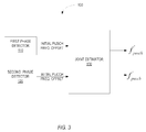
- Fig. 3 illustrates the main functional components of a frequency offset estimator 100 according to one exemplary embodiment.
- the functional components shown in Fig. 3 represent logical functions of the frequency offset estimator 100, rather than physical components.
- the logical components may be implemented in a microprocessor, application specific integrated circuit (ASIC), or other digital signal processor.
- ASIC application specific integrated circuit
- the frequency offset estimator 100 comprises first and second phase detectors 110 and 120, respectively.
- a first received signal received on a first channel is input to the first phase detector 110, and a second signal received on a second channel is input to the second phase detector 120.
- the first signal is received on the physical uplink shared channel (PUSCH) in an LTE system.
- the second signal is received on the physical uplink control channel (PUCCH) in an LTE system.
- the first phase detector 110 generates an initial frequency offset estimate based on the phase difference between PUSCH reference symbols.
- the second phase detector 120 determines an initial frequency offset estimate for the PUCCH based on the phase difference between PUCCH reference symbols.
- the initial frequency offsets from the phase detectors 110, 120 are applied to a joint estimator 130. Joint estimator 130 resolves ambiguity in the initial frequency offset estimates and generates the final frequency offset estimates for the PUSCH and PUCCH, respectively. The ambiguity in initial frequency offset estimates is resolved using a joint estimation technique as herein described.
- the joint estimator 130 exploits the difference in the periodicity of the reference symbols for the two channels considered.
- the time interval of the pilot symbols is 0.5 ms for the PUSCH, which equates to a maximum resolvable frequency offset of ⁇ 1000 Hz.
- the time interval of the reference symbols is approximately 4/14 milliseconds, which equates to a resolvable frequency offset of ⁇ 1750 Hz. Wrap-around occurs when the actual frequency offset exceeds the maximum resolvable frequency offset.
- the apparent phase shift for a frequency offset of -1750 Hz is the same as a frequency offset of +250 Hz.
- Joint estimator 130 considers the initial frequency offsets jointly to resolve the ambiguity of the initial frequency offsets. Under ideal conditions, e.g., assuming that the frequency offset during PUSCH transmission is the same as the frequency offset during PUCCH transmission, the maximum resolvable frequency offset can be expanded to 7000 Hz.
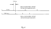
- Fig. 4 illustrates how joint estimation extends the resolvable frequency offset range.
- the minimum change interval will be 1/14 ms, which equals the greatest common factor between the 0.5 ms time interval for PUSCH and the 0.285 ms time interval for the PUCCH.
- the maximum resolvable frequency offset without aliasing is therefore 14,000/2, which equals 7000 Hz.
- the PUSCH and PUCCH transmissions happen at different times and with time varying frequency offsets. Thus, the practical maximum resolvable frequency offset will be smaller than 7000 Hz.
- the scheduler 60 at the base station 10 schedules PUCCH format 2 and PUSCH transmissions on a regular basis.
- the transmission intervals of the PUSCH and PUCCH may be different.
- the PUSCH has a shorter transmission interval than the PUCCH.
- the PUSCH and PUCCH provide two different sets of reference symbols for frequency offset estimation. Also, as previously noted, the resolvable frequency offset range for the PUCCH and PUSCH are different due to the different reference symbol timing.
- the frequency offset estimation procedure can be broken down into four basic steps.
- initial frequency offset estimates are generated for the PUSCH and PUCCH, e.g., by the first and second phase detectors 110, 120.
- the initial frequency offset estimates may be determined in a conventional manner by measuring the phase difference of the reference symbols. That is, the frequency offset for the PUSCH is determined by measuring the phase difference of the PUSCH reference symbols and the initial frequency offset for the PUCCH is made by measuring the phase difference of the PUCCH reference symbols.
- the initial frequency estimates will fall within the respective resolvable ranges for the PUSCH and PUCCH. Thus, the initial frequency offset estimate for the PUSCH will be ⁇ 1000 Hz and the initial frequency offset estimate for the PUCCH will be ⁇ 1750 Hz.
- the initial frequency offset estimates may be averaged over time to improve the robustness against noise.
- the second step of the frequency offset estimation procedure is the construction of a hypothesis table.
- the hypothesis table divides the frequency offset range of [0,7000] Hz into 10 offset regions as shown in Table 1 below.
- Table 1 Offset Regions Index of hypothesis regions: i h PUSCH wrap-around number: n pusch wrap PUCCH wrap-around number: n pucch wrap
- Table 1 Offset Regions Index of hypothesis regions: i h PUSCH wrap-around number: n pusch wrap PUCCH wrap-around number: n pucch wrap
- the boundaries between the offset regions are integer multiples of the wrapping thresholds for the PUSCH and/or PUCCH.
- the wrapping threshold for the PUSCH is ⁇ 1000 Hz and the wrapping threshold for the PUCCH is ⁇ 1750 Hz.
- Each offset region corresponds to a predetermined number of wraps, i.e. the wrap-around number, for the PUSCH and PUCCH.
- Table 1 gives the wrap-around number for each offset region for the PUSCH and PUCCH, where the combination of wrap-around numbers for the PUSCH and PUCCH is unique in each offset region. Based on the initial frequency offset estimates, the wrap-around numbers, and the wrapping threshold, hypothesized frequency offsets for the PUSCH and PUCCH can be derived for each offset region
- the third step of the frequency offset estimation procedure is to compute an error metric for each offset region. Assuming that the actual frequency offset for the PUSCH and PUCCH is the same, the hypothesized frequency offsets for the PUCCH and PUSCH in any given offset region would be equal. In practice, there is likely to be some variance between the frequency offset estimates for the PUSCH and PUCCH. Accordingly, embodiments of the present invention use an error metric based on the difference between the hypothesized frequency offsets for the PUSCH and PUCCH. Also, the error metric may also take into account a difference between the hypothesized frequency offset for the PUSCH (or PUCCH) in the current transmission interval and the final frequency offset for the preceding transmission interval. The computation of the error metrics is described in greater detail below.
- the final step of the frequency offset estimation procedure is to select final frequency offset estimates from the set of hypothesized estimates.
- the final frequency offset estimates will be the set of hypothesized frequency offsets that minimize the error metric.
- the PUSCH is normally scheduled more often than PUCCH.
- the PUSCH frequency offset is chosen from its hypothesis table with the one whose value is the closest to previous ambiguity resolved PUSCH frequency offset estimate.
- the first term of the error metric is a difference between the hypothesized frequency offsets for the PUSCH and PUCCH.
- the second term is the difference between the hypothesized frequency offsets for the current and preceding PUSCH subframes.
- the coefficient ⁇ is a predetermined weighting factor.
- i h min arg min i h ⁇ 0 1 2 ..9 E h .
- a new hypothesized frequency offset is computed only for the PUSCH in each offset region according to Eqs. (4) and (5).
- an error metric E h is computed for each offset region.
- the offset region that minimizes the error metric is found according to Eq. (9).
- the new frequency offset estimate for the PUSCH is then given by Eq. (10).
- new hypothesized frequency offsets may be computed for each offset region i h according to Eqs. (6) and (7).
- an error metric E h is computed for each offset region.
- the offset region that minimizes the error metric is found according to Eq. (9).
- the new frequency offset estimate for the PUCCH is then given by Eq. (11).
- the frequency ambiguity is resolved in PUSCH subframes with new PUCCH raw frequency offset estimates.
- the error metric takes into account the differences between the hypothesized frequency offsets for the PUSCH and PUCCH.
- the hypothesized frequency offsets in the offset region that minimizes the error metric are likely to be the correct estimates.
- new hypothesized frequency offsets are computed according to Eqs. (14) - (19).
- An error metric for each offset region is then computed according to Eq. (8) and the offset region that minimizes the error metric is selected according to Eq. (9).
- the final frequency offset estimates for the PUSCH and PUCCH are then given by Eqs. (10) and (11), respectively.
- new hypothesized frequency offsets are computed only for the PUSCH according to Eqs. (14) - (16).
- An error metric for each offset region is then computed according to Eq. (12) and the offset region that minimizes the error metric is selected according to Eq. (9).
- the final frequency offset estimate for the PUSCH is then given by Eq. (10).
- the maximum frequency offset may be assumed to be below 1750 Hz. In this case, there is no wrap-around in the PUCCH frequency offset estimates and the hypothesis table reduces to two offset regions.
- the hypothesized frequency offsets for the PUSCH are given by Eqs. (14) and (15).
- the hypothesized frequency offsets for the PUCCH are given by Eqs. (17) and (18).
- new hypothesized frequency offsets are computed according to Eqs. (14) - (15) and Eqs. (17) - (18).
- An error metric for each offset region is then computed according to Eq. (8) and the offset region that minimizes the error metric is selected according to Eq. (9).
- the final frequency offset estimates for the PUSCH and PUCCH are then given by Eqs. (10) and (11) respectively.
- new hypothesized frequency offsets are computed only for the PUSCH according to Eqs. (14) - (15).
- An error metric for each offset region is then computed according to Eq. (12) and the offset region that minimizes the error metric is selected according to Eq. (9).
- the final frequency offset estimate for the PUSCH is then given by Eq. (10).
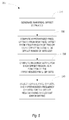
- Fig. 5 illustrates a generalized form of the joint estimation procedure 200 as herein described.
- the procedure 200 shown in Fig. 5 begins with the generation of raw frequency offset estimates for first and second channels having different resolvable ranges (block 210). Hypothesized frequency offsets are then computed from the raw frequency offset estimates for each one of two or more offset regions in an offset range of interest (block 220). For each offset region, an error metric is computed as a function of the corresponding hypothesized frequency offsets for the first and second channels (block 230). The set of hypothesized frequency offsets that minimizes the error metric is then selected as the final frequency offset estimates (block 240).
- the embodiments described herein expand the resolvable frequency offset range, which allows for more accurate estimation of the frequency offset under HST conditions in LTE. More accurate frequency offset estimation paves the way for proper frequency offset compensation, thus ensuring a certain level of throughput performances.
- the embodiments described herein require very little extra computing resource to implement.
Landscapes
- Engineering & Computer Science (AREA)
- Computer Networks & Wireless Communication (AREA)
- Signal Processing (AREA)
- Databases & Information Systems (AREA)
- Mobile Radio Communication Systems (AREA)
Description
- The present invention relates generally to frequency correction in a mobile communication terminal and, more particularly, to the estimation of the frequency offset between a base station and mobile terminal in a mobile communication network.
- In mobile telecommunication systems, there is typically frequency offset between the transmitter and the receiver. The frequency offset can be caused by oscillator mismatch in the transmitter and the receiver and/or Doppler shift. Under certain channel conditions, the frequency offset due to Doppler shift can be quite large, i.e. greater that 1 kHz. One scenario where large frequency offsets are expected is the high speed train (HST) scenario as defined in the Third Generation Partnership Project (3GPP) specification TS 36.104 where the user is traveling on a high speed train. Due to large Doppler shift in the HST scenario, the frequency offset can be ± 2 kHz for the Evolved Universal Terrestrial Radio Access (E-UTRA) operating band 7 frequency. For the mobile communication systems to work properly, a frequency offset of this magnitude must be estimated and corrected.
- Simple and effective algorithms exist to estimate the frequency offset. One common approach estimates the frequency offset based on the phase differences of reference symbols (or pilot symbols). The frequency offset foffset is estimated as the phase difference ΔΦ divided by the time interval Δt of the pilot symbols, and may be given by:

- Because the observable phase difference is limited to an absolute value less than π, the time interval of the pilot symbols determines the maximum frequency offset range that can be estimated. For the Physical Uplink Shared Channel (PUSCH) in LTE systems, the time interval of the reference symbols is 0.5 ms. The maximum frequency offset that can be estimated from PUSCH reference symbols is ±1000Hz. For the Physical Uplink Control Channel (PUCCH) using
format 2/2a/2b, the time interval for the reference symbols is approximately 4/14 ms. The maximum frequency offset that can be estimated from PUCCH reference symbols is thus ±1750Hz. If the frequency offset is beyond these ranges, the phase differences of the reference symbols will "wrap-around" π or- π. The "wrap-around" frequencies corresponding to the phase differences of ±π are ±1000 Hz for PUSCH and ±1750 Hz for PUCCH. - The wrap-around effect creates ambiguity in estimating the frequency offset. For example, a frequency offset of -1750 Hz for the PUSCH will cause phase rotation and end up at point A in the complex plane as shown in
Figure 1 . Similarly, a frequency offset of +250Hz will cause a phase rotation of
- 3GPP draft R4-081041 titled "Test Model for High Speed Train" by NEC, suggests including PUCCH (format 2) for the measure model for the high speed train scenario.
- A method for increasing the resolvable range of frequency offsets is described in the patent application
WO 2010/060732 "Frequency Offset Estimation" combining two frequency offset estimates on the same received signal. In this disclosure, the two estimates are calculated from pairs of received symbols with different time difference between the first and the last received symbol. However, for each PUSCH andPUCCH format 2/2a/2b there is only one time difference between the reference symbols located in the same part of the spectrum so it is not possible to resolve the ambiguity from a single received signal. Furthermore, the PUSCH and PUCCH can not be scheduled in the same subframe for the same user and one channel (PUSCH for example) may be scheduled more frequently than the other (PUCCH for example). Thus, there will be instances where there are no fresh raw estimates from both channels. In these cases, a channel has to resolve the ambiguity with its own single raw estimate. - Therefore, new techniques are needed for extending the resolvable range of frequency offsets.
- The present invention provides methods and apparatus for estimating the frequency offset between a transmitter and a receiver. The present invention exploits the differences in reference symbol timing for different channels to resolve ambiguities in the frequency offset estimation. Based on the initial frequency offset estimates, a hypothesis table is constructed providing hypothesized frequency offsets for each channel for a plurality of possible offset regions. An error metric for each offset region is calculated based on the difference between the hypothesized frequency offsets. The set of hypothesized frequency offsets that minimizes the error metric is selected as the final frequency offset estimates.
- Exemplary embodiments comprise a method implemented in a receiving node of a wireless network for determining a frequency offset between a transmitting station and a receiving station. In one exemplary method, raw frequency offset estimates are generated for first and second channels having different resolvable ranges. A first hypothesized frequency offset is computed for the first channel and a second hypothesized frequency offset is computed for the second channel for each one of two or more offset regions within an offset range of interest. For each offset region, an error metric is computed as a function of the corresponding hypothesized frequency offsets for the first and second channels. The hypothesized frequency offsets corresponding to the offset region having the lowest error metric are selected as final frequency offset estimates.
- Other embodiments of the invention comprise a receiving node in wireless network. The receiving node comprises a receiver front end for receiving signals from a transmitting node over a wireless channel and a processing circuit to estimate a frequency offset between the receiving node and transmitting node. The processing circuit is configured to generate raw frequency offset estimates for first and second channels having different resolvable ranges. The processing circuit computes, from the raw frequency offset estimates, a first hypothesized frequency offset for the first channel and a second hypothesized frequency offset for the second channel for each one of two or more offset regions within a region of interest. The processing circuit then computes an error metric for each offset region as a function of the corresponding hypothesized frequency offsets for the first and second channels. Finally, the processing circuit selects, as final frequency offset estimates, the hypothesized frequency offsets corresponding to the offset region having the lowest error metric.
- In some embodiments, the frequency offset selected in a first time interval is used to select the frequency offset in a subsequent time interval. More particularly, the processing circuit may select a hypothesized frequency offset in a second time interval that is the closest to the selected frequency offset in the first time interval.
- The frequency offset estimation techniques herein described expand the resolvable frequency offset range, which allows for more accurate estimation of the frequency offset with only a slight increase in computing resources. More accurate frequency offset estimation paves the way for proper frequency offset compensation, thus ensuring a higher level of throughput performance.
-
-
Fig. 1 illustrates the aliasing problem in frequency offset estimation. -
Fig. 2 illustrates an exemplary base station according to one embodiment of the invention including a frequency offset estimator. -
Fig. 3 illustrates the main functional components of the frequency offset estimator. -
Fig. 4 illustrates how joint estimation extends the resolvable frequency offset range. -
Fig. 5 illustrates an exemplary method according to one embodiment. -
Fig. 2 illustrates anexemplary base station 10 according to one exemplary embodiment.Base station 10 is configured to operate according to the Long Term Evolution (LTE) standard by the 3rd Generation Partnership Project (3GPP). Those skilled in the art will appreciate that the principals described herein may be applied to mobile communication networks based on other communication standards including, without limitation, Wideband Co-Division Multiple Access (WCDMA) systems, WiMax systems, and wireless local area networks (WLAN). -
Base station 10 comprises atransceiver circuit 20 andprocessing circuit 50.Transceiver circuit 20 comprises the radio equipment for communicating over the air interface with mobile terminals via antenna 22. Thetransceiver circuit 20 comprises areceiver front end 30 andtransmitter front end 40. Receiverfront end 30 downconverts the received signal to baseband frequency, amplifies and filters the received signal, and converts the received signal to digital form for input to theprocessing circuit 50. Transmitterfront end 40 converts signals supplied by theprocessing circuit 50 to analog form, filters and amplifies the signal, and modulates the signal onto an RF carrier for transmission to the mobile terminal via antenna 22. - The
processing circuit 50 performs the digital signal processing for transmitted and received signals, and controls the operation of thebase station 10 according to the applicable communication standard. Processingcircuit 50 demodulates and decodes the received signals supplied by the receiverfront end 30. Theprocessing circuit 50 also encodes and modulates signals to be transmitted to the mobile terminal by the transmitterfront end 40. Processingcircuit 50 includes ascheduler 60 and a frequency offsetestimator 100. The frequency offsetestimator 100 estimates a frequency offset between the transmitter at the mobile terminal and the receiver at thebase station 10. The frequency offset may be due to variances in the oscillator and Doppler shift. The frequency offsetestimator 100 applies frequency correction to correct for the estimated offset. Thescheduler 60 handles radio resource management and schedules transmissions to the mobile terminal on the downlink channels, and transmissions from the mobile terminal on the uplink channels. Those skilled in the art will appreciate that theprocessing circuit 50 performs many other functions which are not essential to the understanding of the present invention. -
Fig. 3 illustrates the main functional components of a frequency offsetestimator 100 according to one exemplary embodiment. Those skilled in the art will appreciate that the functional components shown inFig. 3 represent logical functions of the frequency offsetestimator 100, rather than physical components. The logical components may be implemented in a microprocessor, application specific integrated circuit (ASIC), or other digital signal processor. - The frequency offset
estimator 100 comprises first andsecond phase detectors 110 and 120, respectively. A first received signal received on a first channel is input to thefirst phase detector 110, and a second signal received on a second channel is input to the second phase detector 120. In one exemplary embodiment, the first signal is received on the physical uplink shared channel (PUSCH) in an LTE system. The second signal is received on the physical uplink control channel (PUCCH) in an LTE system. Thefirst phase detector 110 generates an initial frequency offset estimate based on the phase difference between PUSCH reference symbols. Similarly, the second phase detector 120 determines an initial frequency offset estimate for the PUCCH based on the phase difference between PUCCH reference symbols. The initial frequency offsets from thephase detectors 110, 120 are applied to ajoint estimator 130.Joint estimator 130 resolves ambiguity in the initial frequency offset estimates and generates the final frequency offset estimates for the PUSCH and PUCCH, respectively. The ambiguity in initial frequency offset estimates is resolved using a joint estimation technique as herein described. - The
joint estimator 130 exploits the difference in the periodicity of the reference symbols for the two channels considered. Continuing with the LTE example, the time interval of the pilot symbols is 0.5 ms for the PUSCH, which equates to a maximum resolvable frequency offset of ±1000 Hz. For thePUCCH using format 2/2A/2B, the time interval of the reference symbols is approximately 4/14 milliseconds, which equates to a resolvable frequency offset of ±1750 Hz. Wrap-around occurs when the actual frequency offset exceeds the maximum resolvable frequency offset. For the PUSCH, the apparent phase shift for a frequency offset of -1750 Hz is the same as a frequency offset of +250 Hz. -
Joint estimator 130 considers the initial frequency offsets jointly to resolve the ambiguity of the initial frequency offsets. Under ideal conditions, e.g., assuming that the frequency offset during PUSCH transmission is the same as the frequency offset during PUCCH transmission, the maximum resolvable frequency offset can be expanded to 7000 Hz.Fig. 4 illustrates how joint estimation extends the resolvable frequency offset range. When combining the PUSCH and PUCCH, the minimum change interval will be 1/14 ms, which equals the greatest common factor between the 0.5 ms time interval for PUSCH and the 0.285 ms time interval for the PUCCH. The maximum resolvable frequency offset without aliasing is therefore 14,000/2, which equals 7000 Hz. In practical applications, the PUSCH and PUCCH transmissions happen at different times and with time varying frequency offsets. Thus, the practical maximum resolvable frequency offset will be smaller than 7000 Hz. - The
scheduler 60 at thebase station 10schedules PUCCH format 2 and PUSCH transmissions on a regular basis. The transmission intervals of the PUSCH and PUCCH may be different. Typically, the PUSCH has a shorter transmission interval than the PUCCH. The PUSCH and PUCCH provide two different sets of reference symbols for frequency offset estimation. Also, as previously noted, the resolvable frequency offset range for the PUCCH and PUSCH are different due to the different reference symbol timing. - The frequency offset estimation procedure can be broken down into four basic steps. In the first step, initial frequency offset estimates are generated for the PUSCH and PUCCH, e.g., by the first and
second phase detectors 110, 120. The initial frequency offset estimates may be determined in a conventional manner by measuring the phase difference of the reference symbols. That is, the frequency offset for the PUSCH is determined by measuring the phase difference of the PUSCH reference symbols and the initial frequency offset for the PUCCH is made by measuring the phase difference of the PUCCH reference symbols. The initial frequency estimates will fall within the respective resolvable ranges for the PUSCH and PUCCH. Thus, the initial frequency offset estimate for the PUSCH will be ±1000 Hz and the initial frequency offset estimate for the PUCCH will be ±1750 Hz. The initial frequency offset estimates may be averaged over time to improve the robustness against noise. - The second step of the frequency offset estimation procedure is the construction of a hypothesis table. The hypothesis table divides the frequency offset range of [0,7000] Hz into 10 offset regions as shown in Table 1 below.
Table 1: Offset Regions Index of hypothesis regions: ih PUSCH wrap-around number: 
PUCCH wrap-around number: 
Hypothesis absolute value frequency offset range: 
0 0 0 (0,1000) 1 1 0 (1000,1750) 2 1 1 (1750,2000) 3 2 1 (2000,3000) 4 3 1 (3000,3500) 5 3 2 (3500,4000) 6 4 2 (4000,5000) 7 5 2 (5000,5250) 8 5 3 (5250,6000) 9 6 3 (6000,7000) - The boundaries between the offset regions are integer multiples of the wrapping thresholds for the PUSCH and/or PUCCH. As previously noted, the wrapping threshold for the PUSCH is ±1000 Hz and the wrapping threshold for the PUCCH is ±1750 Hz. Each offset region corresponds to a predetermined number of wraps, i.e. the wrap-around number, for the PUSCH and PUCCH. Table 1 gives the wrap-around number for each offset region for the PUSCH and PUCCH, where the combination of wrap-around numbers for the PUSCH and PUCCH is unique in each offset region. Based on the initial frequency offset estimates, the wrap-around numbers, and the wrapping threshold, hypothesized frequency offsets for the PUSCH and PUCCH can be derived for each offset region
- The third step of the frequency offset estimation procedure is to compute an error metric for each offset region. Assuming that the actual frequency offset for the PUSCH and PUCCH is the same, the hypothesized frequency offsets for the PUCCH and PUSCH in any given offset region would be equal. In practice, there is likely to be some variance between the frequency offset estimates for the PUSCH and PUCCH. Accordingly, embodiments of the present invention use an error metric based on the difference between the hypothesized frequency offsets for the PUSCH and PUCCH. Also, the error metric may also take into account a difference between the hypothesized frequency offset for the PUSCH (or PUCCH) in the current transmission interval and the final frequency offset for the preceding transmission interval. The computation of the error metrics is described in greater detail below.
- The final step of the frequency offset estimation procedure is to select final frequency offset estimates from the set of hypothesized estimates. In some embodiments, the final frequency offset estimates will be the set of hypothesized frequency offsets that minimize the error metric.
- The PUSCH is normally scheduled more often than PUCCH. When there is no new raw PUCCH frequency offset estimates, the PUSCH frequency offset is chosen from its hypothesis table with the one whose value is the closest to previous ambiguity resolved PUSCH frequency offset estimate.
- An exemplary procedure for frequency offset estimation will now be described in more detail. The description uses the following definitions:
- factual : Actual frequency offset in Hz
- fwrap_thresh : A positive number with a unit of Hz denoting the wrap around threshold of frequency offset.


- nwrap : The number of wrap-around that will happen given a frequency offset
- f̂ : The raw frequency offset estimate. Instantaneous frequency offset estimate in the range of (-fwrap_thresh ,0) or (0, fwrap_thresh )
- f̃ : Vector containing the hypothesized estimates of the actual frequency offset based on the triplet: f̂ , fwrap_thresh and hypothesis of nwrap
- f̃ : The unwrapped value of raw frequency offset chosen from f̃
- f' : Ambiguity resolved frequency offset estimate
- f'k-1 : Previous ambiguity resolved frequency offset estimate
- The hypothesized frequency offset for the PUSCH and PUCCH for each offset region can be computed by first computingfrom the raw frequency offset estimate according to:

 is known, the hypothesized frequency offset can be computed according to:

- In PUSCH subframes where new PUCCH raw frequency offset estimates are available since the last PUSCH transmission, new hypothesized frequency offsets are computed for both the PUSCH and PUCCH. Hypothesized frequency offsets for the PUSCH are computed for an offset region ih according to:


- In PUSCH subframes without new PUCCH raw frequency offset estimates, a new hypothesized frequency offset is computed only for the PUSCH in each offset region according to Eqs. (4) and (5). Next, an error metric E h is computed for each offset region. In one exemplary embodiment, the error metric E h is given by:

- In new PUCCH subframes, new hypothesized frequency offsets may be computed for each offset region ih according to Eqs. (6) and (7). Next, an error metric E h is computed for each offset region. In one exemplary embodiment, the error metric E h is given by:

- In the procedure described above, the frequency ambiguity is resolved in PUSCH subframes with new PUCCH raw frequency offset estimates. In these subframes, the error metric takes into account the differences between the hypothesized frequency offsets for the PUSCH and PUCCH. The hypothesized frequency offsets in the offset region that minimizes the error metric are likely to be the correct estimates.
- The general procedure described above works with frequency offsets up to 7000 Hz. In LTE applications, the expected frequency offset is expected to be much lower than 7000 Hz. With a smaller frequency offset, the maximum wrap-around number is smaller, resulting in a smaller hypothesis table. Fewer hypotheses reduce complexity and improve the algorithm robustness. For a band 7 frequency, it can be assumed that the maximum frequency offset is below 2000 Hz. Thus, the hypothesis table reduces to three offset regions. The computation of hypothesized frequency offsets for each offset region simply to:
- For the PUSCH


- For the PUCCH



- In PUSCH subframes with new PUCCH raw frequency estimates, new hypothesized frequency offsets are computed according to Eqs. (14) - (19). An error metric for each offset region is then computed according to Eq. (8) and the offset region that minimizes the error metric is selected according to Eq. (9). The final frequency offset estimates for the PUSCH and PUCCH are then given by Eqs. (10) and (11), respectively.
- In PUSCH subframes without new PUCCH raw frequency estimates, new hypothesized frequency offsets are computed only for the PUSCH according to Eqs. (14) - (16). An error metric for each offset region is then computed according to Eq. (12) and the offset region that minimizes the error metric is selected according to Eq. (9). The final frequency offset estimate for the PUSCH is then given by Eq. (10).
- In PUCCH subframes, new hypothesized frequency offsets are computed for the PUCCH according to Eqs. (17) - (19). An error metric for each offset region is then computed according to Eq. (13) and the offset region that minimizes the error metric is selected according to Eq. (9). The final frequency offset estimate for the PUCCH is then given by Eq. (11).
- For band 1 frequency, the maximum frequency offset may be assumed to be below 1750 Hz. In this case, there is no wrap-around in the PUCCH frequency offset estimates and the hypothesis table reduces to two offset regions. The hypothesized frequency offsets for the PUSCH are given by Eqs. (14) and (15). The hypothesized frequency offsets for the PUCCH are given by Eqs. (17) and (18).
- In PUSCH subframes with new PUCCH raw frequency estimates, new hypothesized frequency offsets are computed according to Eqs. (14) - (15) and Eqs. (17) - (18). An error metric for each offset region is then computed according to Eq. (8) and the offset region that minimizes the error metric is selected according to Eq. (9). The final frequency offset estimates for the PUSCH and PUCCH are then given by Eqs. (10) and (11) respectively.
- In PUSCH subframes without new PUCCH raw frequency estimates, new hypothesized frequency offsets are computed only for the PUSCH according to Eqs. (14) - (15). An error metric for each offset region is then computed according to Eq. (12) and the offset region that minimizes the error metric is selected according to Eq. (9). The final frequency offset estimate for the PUSCH is then given by Eq. (10).
- In PUCCH subframes, new hypothesized frequency offsets are computed for the PUCCH according to Eqs. (17) - (18). An error metric for each offset region is then computed according to Eq. (13) and the offset region that minimizes the error metric is selected according to Eq. (9). The final frequency offset estimate for the PUSCH is then given by Eq. (11).
-
Fig. 5 illustrates a generalized form of thejoint estimation procedure 200 as herein described. Theprocedure 200 shown inFig. 5 begins with the generation of raw frequency offset estimates for first and second channels having different resolvable ranges (block 210). Hypothesized frequency offsets are then computed from the raw frequency offset estimates for each one of two or more offset regions in an offset range of interest (block 220). For each offset region, an error metric is computed as a function of the corresponding hypothesized frequency offsets for the first and second channels (block 230). The set of hypothesized frequency offsets that minimizes the error metric is then selected as the final frequency offset estimates (block 240). - The embodiments described herein expand the resolvable frequency offset range, which allows for more accurate estimation of the frequency offset under HST conditions in LTE. More accurate frequency offset estimation paves the way for proper frequency offset compensation, thus ensuring a certain level of throughput performances. The embodiments described herein require very little extra computing resource to implement.
Claims (14)
- A method of determining a frequency offset between a transmitting station and a receiving station, the method comprising:generating (210) raw frequency offset estimates for first and second channels between the transmitting station and the receiving station, said first and second channels transmitted in different subframes and having different resolvable ranges;computing (220), from the raw frequency offset estimates, a first hypothesized frequency offset for the first channel and a second hypothesized frequency offset for the second channel for each one of two or more offset regions within an offset range of interest;computing (230), for each offset region, an error metric as a function of the corresponding hypothesized frequency offsets for the first and second channels wherein computing the error metric comprises:computing a first difference between the hypothesized frequency offsets for the first and second channels in a first time interval;computing a second difference between the hypothesized frequency offset for the first channel in the first time interval and a final frequency offset for the first channel in a second time interval prior to the first time interval; andcomputing the error metric as a weighted sum of the first and second differences;the method further comprising:selecting (240), as final frequency offset estimates, the hypothesized frequency offsets for the first and second channels corresponding to the offset region having the lowest error metric.
- The method of claim 1 wherein computing the first and second hypothesized frequency offsets for each one of two or more offset regions within a region of interest comprises:determining, for each channel, a wrapping threshold;determining from the wrapping thresholds the offset regions and corresponding wrap-around numbers for the first and second channels such that the combination of wrap-around numbers for the first and second channels is unique in each offset region; andcomputing, for each offset region, the hypothesized frequency offsets for the first and second channels from the raw frequency offset estimates, the wrapping thresholds, and the number of wraps.
- The method of claim 1 wherein generating raw frequency offset estimates for first and second channels comprises measuring a phase difference of reference signals transmitted on said channels.
- The method of claim 1 further comprising:computing, for a second time interval, hypothesized frequency offsets for the first channel for each one of two or more offset regions within a region of interest;computing, for the second time interval, a second error metric from the hypothesized frequency offsets for the first channel in the second time interval and a final frequency offset estimate for the first channel in the first time interval; andselecting, for the second time interval, the hypothesized frequency offset with the lowest second error metric.
- The method of claim 1 further comprising:computing, for a second time interval, hypothesized frequency offsets for the second channel for one or more offset regions within a region of interest;computing, for the second time interval, a second error metric from the hypothesized frequency offsets for the second channel in the second time interval and a final frequency offset estimate for the second channel in the first time interval; andselecting, for the second time interval, the hypothesized frequency offset with the lowest second error metric.
- The method of claim 1 in a Long Term Evolution (LTE) network wherein the first channel comprises the Physical Uplink Shared Channel and the second channel comprises the Physical Uplink Control Channel.
- The method of claim 1 in a Long Term Evolution (LTE) network, wherein the first channel comprises the Physical Uplink Shared Channel (PUSCH) and the second channel comprises the Physical Uplink Control Channel (PUCCH).
- A receiving node (10) in a mobile communication network, said network node comprising:a receiver front end (30) for receiving signals over a wireless channel transmitted from a transmitting node; anda processing circuit (50)connected to said receiver front end to estimate a frequency offset between the receiving node and a transmitting node, said processing circuit comprising a frequency offset estimator configured to:generate raw frequency offset estimates for first and second channels between the transmitting station and the receiving station, said first and second channel transmitted in different subframes and having different resolvable ranges;compute, from the raw frequency offset estimates, a first hypothesized frequency offset for the first channel and a second hypothesized frequency offset for the second channel for each one of two or more offset regions within a region of interest;compute, for each offset region, an error metric as a function of the corresponding hypothesized frequency offsets for the first and second channels by:computing a first difference between the hypothesized frequency offsets for the first and second channels in a first time interval;computing a second difference between the hypothesized frequency offset for the first channel in the first time interval and a final frequency offset for the first channel in a second time interval prior to the first time interval; andcomputing the error metric as a weighted sum of the first and second differences;said frequency estimator being further configured to select, as final frequency offset estimates, the hypothesized frequency offsets for the first and second channels corresponding to the offset region having the lowest error metric.
- The receiving node of claim 8 wherein the frequency offset estimator is configured to compute the first and second hypothesized frequency offsets for each one of two or more offset regions within a region of interest by:determining, for each channel, a wrapping threshold;determining from the wrapping thresholds, the offset regions and corresponding wrap-around numbers for the first and second channels such that the combination of wrap-around numbers for the first and second channels is unique in each offset region; andcomputing, for each offset region, the hypothesized frequency offsets for the first and second channels from the raw frequency offset estimates, the wrapping thresholds, and the number of wraps.
- The receiving node of claim 8 wherein said frequency offset estimator is configured to generate raw frequency offset estimates for first and second channels by measuring a phase difference of reference signals transmitted on said channels.
- The receiving node of claim 8 wherein the frequency offset estimator is configured to compute an error metric for each offset region by:computing, for a second time interval, hypothesized frequency offsets for the first channel for each one of two or more offset regions within a region of interest;computing, for the second time interval, a second error metric from the hypothesized frequency offsets for the first channel in the second time interval and a final frequency offset estimate for the first channel in the first time interval; andselecting, for the second time interval, the hypothesized frequency offset with the lowest second error metric.
- The receiving node of claim 8 wherein the frequency offset estimator is configured to compute an error metric for each offset region by:computing, for a second time interval, hypothesized frequency offsets for the second channel for one or more offset regions within a region of interest;computing, for the second time interval, a second error metric from the hypothesized frequency offsets for the second channel in the second time interval and a final frequency offset estimate for the second channel in the first time interval; andselecting, for the second time interval, the hypothesized frequency offset with the lowest second error metric.
- The receiving node of claim 8 in a Long Term Evolution (LTE) network wherein the first channel comprises the Physical Uplink Shared Channel and the second channel comprises the Physical Uplink Control Channel.
- The receiving node of claim 8 configured for a Long Term Evolution (LTE) network wherein the wherein the first channel comprises the Physical Uplink Shared Channel (PUSCH) and the second channel comprises the Physical Uplink Control Channel (PUCCH).
Applications Claiming Priority (2)
| Application Number | Priority Date | Filing Date | Title |
|---|---|---|---|
| US13/170,930 US8605799B2 (en) | 2011-06-28 | 2011-06-28 | Estimation of frequency offset between a base station and mobile terminal |
| PCT/IB2012/053264 WO2013001474A1 (en) | 2011-06-28 | 2012-06-27 | Estimation of frequency offset between a base station and mobile terminal |
Publications (2)
| Publication Number | Publication Date |
|---|---|
| EP2727425A1 EP2727425A1 (en) | 2014-05-07 |
| EP2727425B1 true EP2727425B1 (en) | 2016-04-27 |
Family
ID=46727265
Family Applications (1)
| Application Number | Title | Priority Date | Filing Date |
|---|---|---|---|
| EP12750810.9A Active EP2727425B1 (en) | 2011-06-28 | 2012-06-27 | Estimation of frequency offset between a base station and mobile terminal |
Country Status (4)
| Country | Link |
|---|---|
| US (3) | US8605799B2 (en) |
| EP (1) | EP2727425B1 (en) |
| AU (1) | AU2012277420A1 (en) |
| WO (1) | WO2013001474A1 (en) |
Families Citing this family (9)
| Publication number | Priority date | Publication date | Assignee | Title |
|---|---|---|---|---|
| US8605799B2 (en) | 2011-06-28 | 2013-12-10 | Telefonaktiebolaget L M Ericsson (Publ) | Estimation of frequency offset between a base station and mobile terminal |
| US9532326B2 (en) | 2012-05-14 | 2016-12-27 | Telefonaktiebolaget Lm Ericsson (Publ) | Frequency offset estimation between a mobile communication terminal and a network node |
| US9374727B2 (en) | 2014-03-05 | 2016-06-21 | Qualcomm Incorporated | Calibration and tracking to assist inter-frequency measurements of LTE cell by WLAN radio |
| US9307424B2 (en) * | 2014-03-05 | 2016-04-05 | Qualcomm Incorporated | Calibration and tracking to assist inter-frequency measurements of LTE cell by WLAN radio |
| WO2016032982A1 (en) | 2014-08-25 | 2016-03-03 | Rf Digital Corporation | Push user interface |
| ES2782950T3 (en) * | 2014-09-24 | 2020-09-16 | Guangdong Oppo Mobile Telecommunications Corp Ltd | Wireless communication method and device to estimate the frequency offset of the received signal |
| US10171278B2 (en) * | 2016-05-12 | 2019-01-01 | Cavium, Llc | Methods and apparatus for frequency offset estimation |
| WO2024091225A1 (en) * | 2022-10-25 | 2024-05-02 | Altiostar Networks, Inc. | Network side receiver for receiving high velocity transmitted signals |
| WO2024107165A1 (en) * | 2022-11-14 | 2024-05-23 | Altiostar Networks, Inc. | Network side receiver for receiving high velocity transmitted signals |
Family Cites Families (8)
| Publication number | Priority date | Publication date | Assignee | Title |
|---|---|---|---|---|
| US7453792B2 (en) * | 2002-11-14 | 2008-11-18 | Edgewater Computer Systems, Inc. | Receiver architecture for pilot based OFDM systems |
| US20040202234A1 (en) | 2003-04-11 | 2004-10-14 | Agency For Science, Technology And Research | Low-complexity and fast frequency offset estimation for OFDM signals |
| US7912137B2 (en) * | 2006-01-11 | 2011-03-22 | Amicus Wireless Technology Ltd. | OFDMA device and method of correcting frequency offset in OFDMA signals |
| WO2010021014A1 (en) * | 2008-08-21 | 2010-02-25 | 富士通株式会社 | Device and method for estimating frequency deviation |
| ATE519309T1 (en) | 2008-11-03 | 2011-08-15 | Ericsson Telefon Ab L M | ESTIMATION OF A FREQUENCY CONVERSION |
| US8213406B2 (en) * | 2010-04-12 | 2012-07-03 | Motorola Mobility, Inc. | Uplink time synchronization in a communication system |
| EP2617172A4 (en) | 2010-09-17 | 2016-04-20 | Ericsson Telefon Ab L M | A receiver node and a method therein for compensating frequency offset |
| US8605799B2 (en) | 2011-06-28 | 2013-12-10 | Telefonaktiebolaget L M Ericsson (Publ) | Estimation of frequency offset between a base station and mobile terminal |
-
2011
- 2011-06-28 US US13/170,930 patent/US8605799B2/en not_active Expired - Fee Related
-
2012
- 2012-06-27 AU AU2012277420A patent/AU2012277420A1/en not_active Abandoned
- 2012-06-27 EP EP12750810.9A patent/EP2727425B1/en active Active
- 2012-06-27 WO PCT/IB2012/053264 patent/WO2013001474A1/en not_active Ceased
-
2013
- 2013-11-08 US US14/074,847 patent/US9014314B2/en active Active
-
2015
- 2015-04-20 US US14/691,031 patent/US9609612B2/en not_active Expired - Fee Related
Also Published As
| Publication number | Publication date |
|---|---|
| US9014314B2 (en) | 2015-04-21 |
| EP2727425A1 (en) | 2014-05-07 |
| AU2012277420A1 (en) | 2014-01-16 |
| US9609612B2 (en) | 2017-03-28 |
| US20140105053A1 (en) | 2014-04-17 |
| US8605799B2 (en) | 2013-12-10 |
| US20130003880A1 (en) | 2013-01-03 |
| WO2013001474A1 (en) | 2013-01-03 |
| US20150230193A1 (en) | 2015-08-13 |
Similar Documents
| Publication | Publication Date | Title |
|---|---|---|
| US9609612B2 (en) | Estimation of frequency offset between a base station and mobile terminal | |
| JP5803795B2 (en) | Receiver, frequency deviation calculation method, and computer program | |
| US8744020B2 (en) | Frequency offset estimation | |
| EP3729755B1 (en) | Method and device for transmitting ofdm signal, and method and device for receiving ofdm signal | |
| US10554355B2 (en) | Station (STA) and method for usage of phase noise compensation based on operational parameters | |
| CN108566266B (en) | Reliable transmission method and device for broadband private network under high-speed mobile channel | |
| EP2437450A1 (en) | Device and method for estimating time offset in orthogonal frequency division multiplexing (ofdm) system | |
| KR101646522B1 (en) | Apparatus and method for frequency offset estimation in mobile communication system | |
| WO2018202038A1 (en) | Uplink synchronization timing deviation determination method and device | |
| US20100290356A1 (en) | Wimax communication system and method | |
| US20150103965A1 (en) | Temperature compensated carrier offset correction of a received signal | |
| US8045538B2 (en) | Wireless communication method, receiving method, and wireless communication device | |
| EP2665207B1 (en) | User Equipment and Method for Radio Link Monitoring | |
| US8718206B2 (en) | Frequency correction circuit, frequency correction method and wireless communication equipment using them | |
| US8412271B2 (en) | Boosted, dedicated reference signal | |
| KR102023373B1 (en) | Method and apparatus for timing acquisition in code division multiple access system | |
| US20160036573A1 (en) | Receiving apparatus in wireless communication system and channel estimation control method | |
| US8520777B2 (en) | Operation of user equipment when control and data information are supplied by different radio units | |
| US9628303B2 (en) | Receiver apparatus and frequency selectivity interference correction method | |
| KR20050104427A (en) | Method and apparatus for network management using perceived signal to noise and interference indicator | |
| EP2745406A1 (en) | Method for controlling performance in a radio base station arranged for communication in tdd mode, and radio base station | |
| US9413563B2 (en) | Method and apparatus for channel estimation using localized SINR in wireless communication systems | |
| JP2011114386A (en) | Base station device, radio communication system and frequency correction method | |
| US20220376751A1 (en) | Wireless receiving apparatus, wireless communication system, and wireless receiving method | |
| Chavva et al. | LTE Rel-13 MTC device receiver algorithms for coverage enhancement |
Legal Events
| Date | Code | Title | Description |
|---|---|---|---|
| PUAI | Public reference made under article 153(3) epc to a published international application that has entered the european phase |
Free format text: ORIGINAL CODE: 0009012 |
|
| 17P | Request for examination filed |
Effective date: 20131205 |
|
| AK | Designated contracting states |
Kind code of ref document: A1 Designated state(s): AL AT BE BG CH CY CZ DE DK EE ES FI FR GB GR HR HU IE IS IT LI LT LU LV MC MK MT NL NO PL PT RO RS SE SI SK SM TR |
|
| DAX | Request for extension of the european patent (deleted) | ||
| GRAP | Despatch of communication of intention to grant a patent |
Free format text: ORIGINAL CODE: EPIDOSNIGR1 |
|
| INTG | Intention to grant announced |
Effective date: 20151106 |
|
| RAP1 | Party data changed (applicant data changed or rights of an application transferred) |
Owner name: TELEFONAKTIEBOLAGET L M ERICSSON (PUBL) |
|
| GRAS | Grant fee paid |
Free format text: ORIGINAL CODE: EPIDOSNIGR3 |
|
| GRAA | (expected) grant |
Free format text: ORIGINAL CODE: 0009210 |
|
| AK | Designated contracting states |
Kind code of ref document: B1 Designated state(s): AL AT BE BG CH CY CZ DE DK EE ES FI FR GB GR HR HU IE IS IT LI LT LU LV MC MK MT NL NO PL PT RO RS SE SI SK SM TR |
|
| REG | Reference to a national code |
Ref country code: GB Ref legal event code: FG4D |
|
| REG | Reference to a national code |
Ref country code: CH Ref legal event code: EP |
|
| REG | Reference to a national code |
Ref country code: AT Ref legal event code: REF Ref document number: 795978 Country of ref document: AT Kind code of ref document: T Effective date: 20160515 |
|
| REG | Reference to a national code |
Ref country code: IE Ref legal event code: FG4D |
|
| REG | Reference to a national code |
Ref country code: DE Ref legal event code: R096 Ref document number: 602012017740 Country of ref document: DE |
|
| REG | Reference to a national code |
Ref country code: FR Ref legal event code: PLFP Year of fee payment: 5 |
|
| REG | Reference to a national code |
Ref country code: LT Ref legal event code: MG4D |
|
| PGFP | Annual fee paid to national office [announced via postgrant information from national office to epo] |
Ref country code: FR Payment date: 20160628 Year of fee payment: 5 |
|
| REG | Reference to a national code |
Ref country code: NL Ref legal event code: MP Effective date: 20160427 |
|
| REG | Reference to a national code |
Ref country code: AT Ref legal event code: MK05 Ref document number: 795978 Country of ref document: AT Kind code of ref document: T Effective date: 20160427 |
|
| PG25 | Lapsed in a contracting state [announced via postgrant information from national office to epo] |
Ref country code: NL Free format text: LAPSE BECAUSE OF FAILURE TO SUBMIT A TRANSLATION OF THE DESCRIPTION OR TO PAY THE FEE WITHIN THE PRESCRIBED TIME-LIMIT Effective date: 20160427 |
|
| PG25 | Lapsed in a contracting state [announced via postgrant information from national office to epo] |
Ref country code: FI Free format text: LAPSE BECAUSE OF FAILURE TO SUBMIT A TRANSLATION OF THE DESCRIPTION OR TO PAY THE FEE WITHIN THE PRESCRIBED TIME-LIMIT Effective date: 20160427 Ref country code: PL Free format text: LAPSE BECAUSE OF FAILURE TO SUBMIT A TRANSLATION OF THE DESCRIPTION OR TO PAY THE FEE WITHIN THE PRESCRIBED TIME-LIMIT Effective date: 20160427 Ref country code: NO Free format text: LAPSE BECAUSE OF FAILURE TO SUBMIT A TRANSLATION OF THE DESCRIPTION OR TO PAY THE FEE WITHIN THE PRESCRIBED TIME-LIMIT Effective date: 20160727 Ref country code: LT Free format text: LAPSE BECAUSE OF FAILURE TO SUBMIT A TRANSLATION OF THE DESCRIPTION OR TO PAY THE FEE WITHIN THE PRESCRIBED TIME-LIMIT Effective date: 20160427 |
|
| PGFP | Annual fee paid to national office [announced via postgrant information from national office to epo] |
Ref country code: DE Payment date: 20160628 Year of fee payment: 5 |
|
| PG25 | Lapsed in a contracting state [announced via postgrant information from national office to epo] |
Ref country code: SE Free format text: LAPSE BECAUSE OF FAILURE TO SUBMIT A TRANSLATION OF THE DESCRIPTION OR TO PAY THE FEE WITHIN THE PRESCRIBED TIME-LIMIT Effective date: 20160427 Ref country code: RS Free format text: LAPSE BECAUSE OF FAILURE TO SUBMIT A TRANSLATION OF THE DESCRIPTION OR TO PAY THE FEE WITHIN THE PRESCRIBED TIME-LIMIT Effective date: 20160427 Ref country code: LV Free format text: LAPSE BECAUSE OF FAILURE TO SUBMIT A TRANSLATION OF THE DESCRIPTION OR TO PAY THE FEE WITHIN THE PRESCRIBED TIME-LIMIT Effective date: 20160427 Ref country code: HR Free format text: LAPSE BECAUSE OF FAILURE TO SUBMIT A TRANSLATION OF THE DESCRIPTION OR TO PAY THE FEE WITHIN THE PRESCRIBED TIME-LIMIT Effective date: 20160427 Ref country code: AT Free format text: LAPSE BECAUSE OF FAILURE TO SUBMIT A TRANSLATION OF THE DESCRIPTION OR TO PAY THE FEE WITHIN THE PRESCRIBED TIME-LIMIT Effective date: 20160427 Ref country code: GR Free format text: LAPSE BECAUSE OF FAILURE TO SUBMIT A TRANSLATION OF THE DESCRIPTION OR TO PAY THE FEE WITHIN THE PRESCRIBED TIME-LIMIT Effective date: 20160728 Ref country code: PT Free format text: LAPSE BECAUSE OF FAILURE TO SUBMIT A TRANSLATION OF THE DESCRIPTION OR TO PAY THE FEE WITHIN THE PRESCRIBED TIME-LIMIT Effective date: 20160829 Ref country code: ES Free format text: LAPSE BECAUSE OF FAILURE TO SUBMIT A TRANSLATION OF THE DESCRIPTION OR TO PAY THE FEE WITHIN THE PRESCRIBED TIME-LIMIT Effective date: 20160427 |
|
| PG25 | Lapsed in a contracting state [announced via postgrant information from national office to epo] |
Ref country code: BE Free format text: LAPSE BECAUSE OF FAILURE TO SUBMIT A TRANSLATION OF THE DESCRIPTION OR TO PAY THE FEE WITHIN THE PRESCRIBED TIME-LIMIT Effective date: 20160427 Ref country code: IT Free format text: LAPSE BECAUSE OF FAILURE TO SUBMIT A TRANSLATION OF THE DESCRIPTION OR TO PAY THE FEE WITHIN THE PRESCRIBED TIME-LIMIT Effective date: 20160427 |
|
| REG | Reference to a national code |
Ref country code: DE Ref legal event code: R097 Ref document number: 602012017740 Country of ref document: DE |
|
| PG25 | Lapsed in a contracting state [announced via postgrant information from national office to epo] |
Ref country code: CZ Free format text: LAPSE BECAUSE OF FAILURE TO SUBMIT A TRANSLATION OF THE DESCRIPTION OR TO PAY THE FEE WITHIN THE PRESCRIBED TIME-LIMIT Effective date: 20160427 Ref country code: MC Free format text: LAPSE BECAUSE OF FAILURE TO SUBMIT A TRANSLATION OF THE DESCRIPTION OR TO PAY THE FEE WITHIN THE PRESCRIBED TIME-LIMIT Effective date: 20160427 Ref country code: SK Free format text: LAPSE BECAUSE OF FAILURE TO SUBMIT A TRANSLATION OF THE DESCRIPTION OR TO PAY THE FEE WITHIN THE PRESCRIBED TIME-LIMIT Effective date: 20160427 Ref country code: EE Free format text: LAPSE BECAUSE OF FAILURE TO SUBMIT A TRANSLATION OF THE DESCRIPTION OR TO PAY THE FEE WITHIN THE PRESCRIBED TIME-LIMIT Effective date: 20160427 Ref country code: RO Free format text: LAPSE BECAUSE OF FAILURE TO SUBMIT A TRANSLATION OF THE DESCRIPTION OR TO PAY THE FEE WITHIN THE PRESCRIBED TIME-LIMIT Effective date: 20160427 Ref country code: DK Free format text: LAPSE BECAUSE OF FAILURE TO SUBMIT A TRANSLATION OF THE DESCRIPTION OR TO PAY THE FEE WITHIN THE PRESCRIBED TIME-LIMIT Effective date: 20160427 |
|
| REG | Reference to a national code |
Ref country code: CH Ref legal event code: PL |
|
| PG25 | Lapsed in a contracting state [announced via postgrant information from national office to epo] |
Ref country code: SM Free format text: LAPSE BECAUSE OF FAILURE TO SUBMIT A TRANSLATION OF THE DESCRIPTION OR TO PAY THE FEE WITHIN THE PRESCRIBED TIME-LIMIT Effective date: 20160427 |
|
| PLBE | No opposition filed within time limit |
Free format text: ORIGINAL CODE: 0009261 |
|
| STAA | Information on the status of an ep patent application or granted ep patent |
Free format text: STATUS: NO OPPOSITION FILED WITHIN TIME LIMIT |
|
| REG | Reference to a national code |
Ref country code: IE Ref legal event code: MM4A |
|
| 26N | No opposition filed |
Effective date: 20170130 |
|
| PG25 | Lapsed in a contracting state [announced via postgrant information from national office to epo] |
Ref country code: CH Free format text: LAPSE BECAUSE OF NON-PAYMENT OF DUE FEES Effective date: 20160630 Ref country code: LI Free format text: LAPSE BECAUSE OF NON-PAYMENT OF DUE FEES Effective date: 20160630 |
|
| PG25 | Lapsed in a contracting state [announced via postgrant information from national office to epo] |
Ref country code: IE Free format text: LAPSE BECAUSE OF NON-PAYMENT OF DUE FEES Effective date: 20160627 Ref country code: SI Free format text: LAPSE BECAUSE OF FAILURE TO SUBMIT A TRANSLATION OF THE DESCRIPTION OR TO PAY THE FEE WITHIN THE PRESCRIBED TIME-LIMIT Effective date: 20160427 |
|
| REG | Reference to a national code |
Ref country code: DE Ref legal event code: R119 Ref document number: 602012017740 Country of ref document: DE |
|
| REG | Reference to a national code |
Ref country code: FR Ref legal event code: ST Effective date: 20180228 |
|
| PG25 | Lapsed in a contracting state [announced via postgrant information from national office to epo] |
Ref country code: DE Free format text: LAPSE BECAUSE OF NON-PAYMENT OF DUE FEES Effective date: 20180103 |
|
| PG25 | Lapsed in a contracting state [announced via postgrant information from national office to epo] |
Ref country code: FR Free format text: LAPSE BECAUSE OF NON-PAYMENT OF DUE FEES Effective date: 20170630 Ref country code: HU Free format text: LAPSE BECAUSE OF FAILURE TO SUBMIT A TRANSLATION OF THE DESCRIPTION OR TO PAY THE FEE WITHIN THE PRESCRIBED TIME-LIMIT; INVALID AB INITIO Effective date: 20120627 |
|
| PG25 | Lapsed in a contracting state [announced via postgrant information from national office to epo] |
Ref country code: IS Free format text: LAPSE BECAUSE OF FAILURE TO SUBMIT A TRANSLATION OF THE DESCRIPTION OR TO PAY THE FEE WITHIN THE PRESCRIBED TIME-LIMIT Effective date: 20160427 Ref country code: MK Free format text: LAPSE BECAUSE OF FAILURE TO SUBMIT A TRANSLATION OF THE DESCRIPTION OR TO PAY THE FEE WITHIN THE PRESCRIBED TIME-LIMIT Effective date: 20160427 Ref country code: CY Free format text: LAPSE BECAUSE OF FAILURE TO SUBMIT A TRANSLATION OF THE DESCRIPTION OR TO PAY THE FEE WITHIN THE PRESCRIBED TIME-LIMIT Effective date: 20160427 Ref country code: MT Free format text: LAPSE BECAUSE OF NON-PAYMENT OF DUE FEES Effective date: 20160630 Ref country code: LU Free format text: LAPSE BECAUSE OF NON-PAYMENT OF DUE FEES Effective date: 20160627 |
|
| PG25 | Lapsed in a contracting state [announced via postgrant information from national office to epo] |
Ref country code: BG Free format text: LAPSE BECAUSE OF FAILURE TO SUBMIT A TRANSLATION OF THE DESCRIPTION OR TO PAY THE FEE WITHIN THE PRESCRIBED TIME-LIMIT Effective date: 20160427 |
|
| PG25 | Lapsed in a contracting state [announced via postgrant information from national office to epo] |
Ref country code: AL Free format text: LAPSE BECAUSE OF FAILURE TO SUBMIT A TRANSLATION OF THE DESCRIPTION OR TO PAY THE FEE WITHIN THE PRESCRIBED TIME-LIMIT Effective date: 20160427 Ref country code: TR Free format text: LAPSE BECAUSE OF FAILURE TO SUBMIT A TRANSLATION OF THE DESCRIPTION OR TO PAY THE FEE WITHIN THE PRESCRIBED TIME-LIMIT Effective date: 20160427 |
|
| PGFP | Annual fee paid to national office [announced via postgrant information from national office to epo] |
Ref country code: GB Payment date: 20250627 Year of fee payment: 14 |